EP3992633B1 - Robotisches flüssigkeitshandhabungssystem - Google Patents
Robotisches flüssigkeitshandhabungssystem Download PDFInfo
- Publication number
- EP3992633B1 EP3992633B1 EP20204248.7A EP20204248A EP3992633B1 EP 3992633 B1 EP3992633 B1 EP 3992633B1 EP 20204248 A EP20204248 A EP 20204248A EP 3992633 B1 EP3992633 B1 EP 3992633B1
- Authority
- EP
- European Patent Office
- Prior art keywords
- opening
- foil
- robotic arm
- robotic
- liquid handling
- Prior art date
- Legal status (The legal status is an assumption and is not a legal conclusion. Google has not performed a legal analysis and makes no representation as to the accuracy of the status listed.)
- Active
Links
Images


Classifications
-
- B—PERFORMING OPERATIONS; TRANSPORTING
- B25—HAND TOOLS; PORTABLE POWER-DRIVEN TOOLS; MANIPULATORS
- B25J—MANIPULATORS; CHAMBERS PROVIDED WITH MANIPULATION DEVICES
- B25J11/00—Manipulators not otherwise provided for
-
- G—PHYSICS
- G01—MEASURING; TESTING
- G01N—INVESTIGATING OR ANALYSING MATERIALS BY DETERMINING THEIR CHEMICAL OR PHYSICAL PROPERTIES
- G01N35/00—Automatic analysis not limited to methods or materials provided for in any single one of groups G01N1/00 - G01N33/00; Handling materials therefor
- G01N35/0099—Automatic analysis not limited to methods or materials provided for in any single one of groups G01N1/00 - G01N33/00; Handling materials therefor comprising robots or similar manipulators
-
- B—PERFORMING OPERATIONS; TRANSPORTING
- B01—PHYSICAL OR CHEMICAL PROCESSES OR APPARATUS IN GENERAL
- B01L—CHEMICAL OR PHYSICAL LABORATORY APPARATUS FOR GENERAL USE
- B01L3/00—Containers or dishes for laboratory use, e.g. laboratory glassware; Droppers
- B01L3/52—Containers specially adapted for storing or dispensing a reagent
- B01L3/523—Containers specially adapted for storing or dispensing a reagent with means for closing or opening
-
- B—PERFORMING OPERATIONS; TRANSPORTING
- B01—PHYSICAL OR CHEMICAL PROCESSES OR APPARATUS IN GENERAL
- B01L—CHEMICAL OR PHYSICAL LABORATORY APPARATUS FOR GENERAL USE
- B01L3/00—Containers or dishes for laboratory use, e.g. laboratory glassware; Droppers
- B01L3/02—Burettes; Pipettes
- B01L3/0286—Ergonomic aspects, e.g. form or arrangement of controls
-
- B—PERFORMING OPERATIONS; TRANSPORTING
- B01—PHYSICAL OR CHEMICAL PROCESSES OR APPARATUS IN GENERAL
- B01L—CHEMICAL OR PHYSICAL LABORATORY APPARATUS FOR GENERAL USE
- B01L3/00—Containers or dishes for laboratory use, e.g. laboratory glassware; Droppers
- B01L3/02—Burettes; Pipettes
- B01L3/0289—Apparatus for withdrawing or distributing predetermined quantities of fluid
- B01L3/0293—Apparatus for withdrawing or distributing predetermined quantities of fluid for liquids
-
- B—PERFORMING OPERATIONS; TRANSPORTING
- B01—PHYSICAL OR CHEMICAL PROCESSES OR APPARATUS IN GENERAL
- B01L—CHEMICAL OR PHYSICAL LABORATORY APPARATUS FOR GENERAL USE
- B01L9/00—Supporting devices; Holding devices
- B01L9/02—Laboratory benches or tables; Fittings therefor
-
- B—PERFORMING OPERATIONS; TRANSPORTING
- B01—PHYSICAL OR CHEMICAL PROCESSES OR APPARATUS IN GENERAL
- B01L—CHEMICAL OR PHYSICAL LABORATORY APPARATUS FOR GENERAL USE
- B01L9/00—Supporting devices; Holding devices
- B01L9/50—Clamping means, e.g. tongs
-
- G—PHYSICS
- G01—MEASURING; TESTING
- G01N—INVESTIGATING OR ANALYSING MATERIALS BY DETERMINING THEIR CHEMICAL OR PHYSICAL PROPERTIES
- G01N35/00—Automatic analysis not limited to methods or materials provided for in any single one of groups G01N1/00 - G01N33/00; Handling materials therefor
- G01N35/02—Automatic analysis not limited to methods or materials provided for in any single one of groups G01N1/00 - G01N33/00; Handling materials therefor using a plurality of sample containers moved by a conveyor system past one or more treatment or analysis stations
- G01N35/04—Details of the conveyor system
-
- B—PERFORMING OPERATIONS; TRANSPORTING
- B01—PHYSICAL OR CHEMICAL PROCESSES OR APPARATUS IN GENERAL
- B01L—CHEMICAL OR PHYSICAL LABORATORY APPARATUS FOR GENERAL USE
- B01L2200/00—Solutions for specific problems relating to chemical or physical laboratory apparatus
- B01L2200/16—Reagents, handling or storing thereof
-
- B—PERFORMING OPERATIONS; TRANSPORTING
- B01—PHYSICAL OR CHEMICAL PROCESSES OR APPARATUS IN GENERAL
- B01L—CHEMICAL OR PHYSICAL LABORATORY APPARATUS FOR GENERAL USE
- B01L2300/00—Additional constructional details
- B01L2300/04—Closures and closing means
- B01L2300/041—Connecting closures to device or container
- B01L2300/044—Connecting closures to device or container pierceable, e.g. films, membranes
-
- G—PHYSICS
- G01—MEASURING; TESTING
- G01N—INVESTIGATING OR ANALYSING MATERIALS BY DETERMINING THEIR CHEMICAL OR PHYSICAL PROPERTIES
- G01N35/00—Automatic analysis not limited to methods or materials provided for in any single one of groups G01N1/00 - G01N33/00; Handling materials therefor
- G01N35/02—Automatic analysis not limited to methods or materials provided for in any single one of groups G01N1/00 - G01N33/00; Handling materials therefor using a plurality of sample containers moved by a conveyor system past one or more treatment or analysis stations
- G01N35/04—Details of the conveyor system
- G01N2035/0401—Sample carriers, cuvettes or reaction vessels
- G01N2035/0403—Sample carriers with closing or sealing means
- G01N2035/0405—Sample carriers with closing or sealing means manipulating closing or opening means, e.g. stoppers, screw caps, lids or covers
Definitions
- the invention relates to a robotic liquid handling system for performing liquid handling tasks in a laboratory environment, and to a computer-implemented method for controlling a robotic arm of a robotic liquid handling system.
- the invention further relates to a computer-readable medium comprising data representing a computer program for performing the computer-implemented method, and to a tool for being picked-up and used by the robotic arm as part of a liquid handling task.
- Robotic liquid handling systems are well-known in the field of laboratory automation. Such robotic liquid handling systems may be used to automate liquid handling tasks, which may include actions such as handling of liquid containers, e.g., by picking-and-placing liquid containers on a worktable, and interacting with the samples contained in the containers, e.g., by dispensing liquids into a sample container or by pipetting actions.
- liquid handling tasks and actions are known as well which may be at least partially automated by such robotic systems.
- robotic liquid handling system it is also known for a robotic liquid handling system to, in addition to handling liquid samples, also handle non-liquid samples or other objects.
- robotic liquid handling systems are often equipped with a gripper as end-effector to move microplates, e.g. from a pipetting position to a shaker, in an incubator, to a thermocycler for PCR or in a microplate reader, or for moving or sorting test tubes.
- An example of a robotic liquid handling system is an automated pipetting system, as for example described in US20150251315 .
- Such an automated pipetting system which may also be simply referred to as a 'pipetting robot', may comprise at least one pipette for aspirating and dispensing liquid samples.
- the robotic arm may be positioned under control of a controller to a given position and may be controlled to carry out a specific action at the given position. This may for example enable a pipette to be lowered into a container to aspirate a liquid therein or to dispense a liquid.
- a drawback of known robotic liquid handling systems is that they may be limited in their ability to automate certain types of actions in liquid handling tasks.
- US 2011/143947 describes a well wash subassembly which includes a piercing probe to pierce and displace seals on wells of the test plate.
- the well wash subassembly also includes a seal removal tool to remove a seal from a well of a test plate. Removing a seal may include piercing the seal on a well of a test plate and, optionally, cutting the seal into sections (e.g., using cutting edges on a piercing tip) and folding the sections against the internal walls of the well.
- One of the objects of the invention is to provide a robotic liquid handling system, and a computer-implemented method for controlling a robotic arm of a robotic liquid handling system, to be able to perform one or more additional types of action when performing liquid handling tasks in a laboratory environment.
- the control and movement of the robotic arm perpendicular to the work area may also be referred to as a control and movement along a Z-axis.
- the robotic arm may move with its end-effector towards and away from the worktable.
- This may for example allow a robotic arm which has a gripper as end-effector to pick up a sample in the workspace, e.g., by lowering the gripper, gripping the sample container, and then lifting the gripper again.
- the Z-axis along which the robotic arm may be moved may correspond to the direction of gravity.
- such movement in the workspace may allow the robotic arm to handle liquid containers and to interact with samples in those containers, and to move in the XY plane above any objects placed on the surface of the work area.
- reagent reservoirs are liquid containers which are typically filled with a liquid reagent for use in a liquid handling process, and which normally have a topside opening via which the reagent may be extracted, e.g., via pipetting, and which is typically sealed by foil, e.g., to prevent contamination and spilling of the liquid reagent before use.
- reagent reservoirs may be opened automatically, i.e., by the robotic liquid handling system, since this may greatly facilitate the efficiency by which certain liquid handling processes which involve the use of reagent reservoirs may be automated using the robotic liquid handling system.
- the opening of the reagent reservoir in the above-stated manner is different from a conventional manual opening of the reagent reservoir and rather tailored to a robotic arm. Namely, by using a sharp cutting tip to create the two flaps in the foil, less horizontal force may be exerted onto the reagent reservoir than when pulling a pull-tab. This means that it may not be needed to hold the reagent reservoir or apply a counterforce thereto with a second robotic arm.
- the clearing of the foil by pushing the flaps downwards may involve a downward force for which a counterforce may be naturally provided by the surface or rack or the like on which the reagent reservoir is placed.
- the opening of the reagent reservoir in the above-stated manner may be independent of the shape, position and/orientation of a pull-tab, and may therefore represent a type of opening which may be easier to automate and in fact may not even require the presence of a pull-tab.
- the downwards pushing of the flaps may still sufficiently clear the opening of the reagent reservoir, thereby avoiding the need to entirely remove the foil from the reagent reservoir.
- the cutting tip and the blunt protrusion may be provided on two opposite ends of a single tool.
- the single tool may for example be gripped by the robotic arm and then, by suitably positioning either the cutting tip or the blunt protrusion relative to the reagent reservoir, either be used to cut the flaps into the foil or to push the flaps downward into the opening of the reagent reservoir.
- Such a single tool may simplify the automation workflow, in that it may not be needed to switch tools while opening the reagent reservoir, which may otherwise require additional time.
- a perforation using such relatively blunt tools may cause the pressure on the foil to gradually increase until the foil abruptly tears, which may cause the liquid in the reagent reservoir to spatter about.
- the inventors have furthermore devised that such opening by perforation may be difficult to control, meaning that the established opening may itself not have a consistent position and/or size relative to the initial position of the disposable tip. Additionally, or alternatively, the outline of the established opening may be frayed due to the unpredictable tearing of the foil.
- Another drawback of such type of opening of the foil sealing the reagent reservoir is that if the liquid level is measured using a capacitive measurement using the disposable tip, this measurement may be disturbed if the disposable tip accidentally touches the frayed border of a metallic sealing foil.
- the above measures may allow additional types of actions in liquid handling tasks to be automated, which previously may have required manual intervention or which previously had to be entirely avoided in liquid handling tasks. This may be highly advantageous in high-throughput applications in which many samples may need to be processed using the robotic liquid handling system.
- robotic liquid handling systems to use reagents in liquid handling task, such use was previously limited to either sealed reagents which were manually opened, or bulk reagents which were poured from flasks into reservoirs.
- the ability to automatically open and use sealed reagents may save time, reduce errors (spilling) and avoid misplacement since sealed reagents are typically barcoded (type of reagent, lot number, expiry date).
- Another advantage of being able to use sealed reagents may be that in open reservoirs, part of the reagent solution may evaporate, for example if too much time has elapsed after the reagent is poured into the reservoir, which may increase the concentration of the reagent and thereby affect assay results.
- the controller may be configured to control the robotic arm to cut a H-shaped or X-shaped pattern in the foil to establish the at least two flaps.
- An H- or X-shaped pattern may be an efficient way to cut at least two flaps into the foil since it may require relatively few cuts.
- the flaps in such H- or X-patterns may have their free-hanging ends adjacent to each other, which means that multiple flaps may be pushed jointly downwards into the reagent reservoir using the blunt protrusion. This may reduce the number or length of actions to be performed by the robotic arm to open the foil, which in turn may lead to an increased throughput.
- the flaps may remain affixed to the foil at or near the sidewall of the reagent reservoir, which means that the flaps, when pushed downwards into the reagent reservoir, do not or not significantly block the opening of the reagent reservoir.
- the controller may be configured to control the robotic arm to cut the H-shaped or X-shaped pattern in the foil by controlling the robotic arm to:
- the robotic arm may cut the central slit along the length of the opening, referring to a longest dimension of the opening. This may result in flaps being created which may be relatively wide but short, in that they may only extend, at the maximum, across half the width of the opening. Such short flaps may not need to be pushed down as far as longer flaps to clear the opening, so that the opening of the reagent reservoir may be easier cleared for access.
- a cutting pattern may be selected so that flaps are cut into the seal which, when sloping downward into the opening due to gravity or by being pushed into the opening, have a size and shape which avoids contact with the reagent in the reservoir, thus minimizing potential contamination.
- the robotic arm may be controlled such that it is avoided for the cutting tip and the blunt protrusion to come into contact with the reagent, thus minimizing potential contamination and spillage.
- the blunt protrusion has a width which spans at least 75% of the width of the opening, and wherein the controller may be configured to control the robotic arm to push the two flaps downwards with the blunt protrusion oriented so that the width of the blunt protrusion is parallelly aligned with the width of the opening.
- the robotic arm may push downwards with the blunt protrusion at a number of positions along the central slit, which may also enable reagent reservoirs which have a rather elongated opening to be sufficiently cleared from the foil. Namely, in case of a rather elongated opening, a single downwards push along the length of the opening may cause the flaps to be insufficiently pushed downwards into the reagent reservoir.
- the flaps may be pressed more towards the sidewalls of the reagent reservoir to as to more fully clear the opening from the foil.
- the controller may be configured to cut the at least two flaps in the foil by controlling the robotic arm to:
- the flaps may be cut into the foil by lateral movement of the cutting tip after it has pierced the foil.
- the cutting tip may be sharp enough to cut the foil in any direction. Compared to a knife or similar directional tool, this may simplify the cutting actions since it may not be needed to reorient the tool in accordance with the direction of cutting. Rather, the tool may be held by the robotic arm and then simply be moved laterally in any desired manner to cut the at least two flaps into the foil.
- the controller may be configured to control the robotic arm to, after moving the cutting tip laterally along a cutting path at the first depth
- the cutting tip may be moved repeatedly along at least part of the cutting path, for example once at a first entry depth and a second time at a second depth which exceeds the first depth. This may ensure that the flaps indeed have been cut into the foil before attempting to push the flaps downwards.
- the reagent reservoir may be a rectangularly-shaped reagent trough.
- the reagent trough standardized dimensions of for example 79 mm (length) x 16 (width) mm or 78 mm (length) x 17.5 mm (width).
- the opening tool may have two opposing surfaces by which the opening tool can be gripped and picked-up, wherein the robotic arm may be arranged to mount a pair of grippers to pick-and-place objects in a workspace of the robotic liquid handling system, and wherein the controller may be configured to control the robotic arm to pick-up the opening tool by gripping the opening tool with the pair of grippers at the two opposing surfaces.
- the opening tool may have a shape which may allow it to be gripped by a robotic arm which is equipped with a pair of grippers.
- a kit-of-parts may be provided comprising the robotic liquid handling system and the opening tool.
- the elongated main body comprises at each respective end of the elongated shape a respective recess, wherein said recesses provide the opposing surfaces to be gripped.
- the cutting tip has pyramidal shape having an apex projecting away from the elongated surface.
- Such a type of cutting tip may be multidirectional, in that it may allow the foil to be cut in different directions, or even omnidirectional, which may allow cutting independent of the orientation of the cutting tip about its longitudinal axis relative to the cutting direction.
- the cutting tip is made of a glass fiber reinforced thermoplastic, such as glass fiber reinforced Polyetheretherketone (PEEK).
- PEEK Polyetheretherketone
- the opening tool may have exterior dimensions which are substantially equal to the reagent reservoir. This may allow the robotic arm, which may be configured to pick-and-place reagent reservoirs, to also pick-up and operate the opening tool with a same type of end-effector, e.g., with the same type of grippers. This may avoid having to change the end-effector between picking-and-placing reagent reservoirs and the opening the foil of reagent reservoirs.
- the robotic liquid handling system may in general comprise a robotic arm which may be configured to, using a cutting tip, cut at least two flaps in the foil of a reagent reservoir, and using a blunt protrusion, push the at least two flaps downwards into the reagent reservoir to partially clear the opening of the reagent reservoir.
- the cutting tip and blunt protrusion may be part of a same tool which may be gripped by the robotic arm, for example using a pair of grippers which are mounted by the robotic arm.
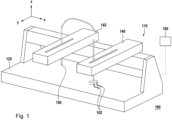
- Fig. 1 shows a robotic liquid handling system 100 which may comprise a robotic liquid handling instrument 110 and a controller 180.
- Fig. 1 shows the robotic liquid handling instrument 110, and thereby the robotic liquid handling system 100, to comprise a work area 120 for holding objects such as liquid samples, racks, etc.
- An example of a work area is a worktable.
- the robotic liquid handling instrument 110, and thereby the robotic liquid handling system 100 is further shown to comprise two robotic arms 140, 142, but may also have one robotic arm or more than two robotic arms.
- each robotic arm 140, 142 may be controllable to be positioned in a XY plane parallel to the work area and along a Z-axis perpendicular to the work area.
- the robotic liquid handling system 100 may comprise the controller 180, which may be configured to control the robotic arms 140, 142 to position and operate a respective robotic arm as part of a liquid handling task.
- the controller 180 may be physically integrated into the robotic liquid handling instrument 110 but may also be an external controller (as shown in Fig. 1 ), such as a PC or workstation.
- Fig. 1 further shows the robotic arms 140, 142 of the robotic liquid handling instrument 110 to comprise different attachments, with one of the robotic arms 142 comprising a liquid handling head having a pipette with a connecting piece (not separately shown) to which a disposable tip 150 is mounted.
- the other robotic arm 140 is shown to comprise a robotic head in the form of a gripper module to which a pair of grippers 162 is mounted.
- Fig. 2 shows the latter type of a robotic head in more detail.
- Fig. 2 shows the gripper module 160 to comprise a pair of grippers 162, with the gripper module 160 being mountable to the robotic arm so as to enable the robotic arm to pick-and-place objects on the worktable 120.
- the robotic liquid handling system may use the pair of grippers 162 to pick-and-place sample containers, such as tubes, or reagent reservoirs.
- the pair of grippers 162 may be moved laterally towards each other in a 'picking-up' or 'gripping'-type of action, and away from each other in a 'releasing'-type of action.
- the pair of grippers 162 may also be used to pick-up an opening tool with which tool the foil of a reagent reservoir may be opened.
- the exemplary opening tool 200 has a main body with an elongated shape, the elongated shape having at each respective end of the elongated shape a recess 210, 212 so as to provide the opening tool 200 with two opposing and recessed surfaces 220, 222 at which the opening tool 200 can be laterally gripped and picked-up, for example by the aforementioned pair of grippers 162 of Figs. 1 and 2 .
- the opening tool 200 is further shown to comprise an elongated downward-facing surface 240 which runs along a length of the main body.
- the elongated surface 240 comprises, at one end, a cutting tip 260 for piercing and cutting the foil of the reagent reservoir, and at an opposing end, a blunt protrusion 280 for pushing flaps cut into the foil downwards into the opening of the reagent reservoir.
- the blunt protrusion may be blunt in relation to the cutting tip, and in general designed not to cut into a foil.
- the blunt protrusion may have at its most distal part a width w 282 which covers at least 50%, or in some cases 75% of a width of the reagent reservoir.
- the blunt protrusion in case of a rectangular reagent reservoir having an opening of 79 mm x 16 mm, the blunt protrusion may have a width of at least 8 mm, or in some embodiments 12 mm.
- the blunt protrusion in case of a rectangular reagent reservoir having an opening of 78 mm x 17.5 mm, the blunt protrusion may have a width of at least 8.75 mm, or in some embodiments 13.125 mm.
- the 'width' w may refer to a dimension of the blunt protrusion along the elongated main body of the opening tool 200, with the 'height' h (286) referring to dimension of the blunt protrusion which is perpendicular to the width w in the plane of Fig. 3A , and with the 'depth' d (284) referring to a dimension of the blunt protrusion which is perpendicularly extends from/into the plane in Fig. 3A .
- the blunt protrusion 280 may have various shapes, such as a substantially cuboid, cylindrical, ellipsoid or (hemi)spherical shape. In other examples, the blunt protrusion 280 may be prism- or wedge-shaped. In general, the blunt protrusion 280 may have a tapered shape, which may be tapered along one dimension. In the specific example of Figs. 3A-3C , the blunt protrusion 280 is shown to be tapered in depth d 284, resulting in the most distal part of the broad protrusion having a relatively small depth d 284 in relation to the width w 282, for example 3-5mm compared to 8-12mm.
- the cutting tip 260 may be suitable for cutting by having a pyramidal or cone-like shape having a single sharp apex and by being made of a sufficiently hard material in relation to the material of the foil.
- the cutting tip 260 may be made out of a glass fiber reinforced thermoplastic, such as glass fiber reinforced Polyetheretherketone (PEEK).
- Fig. 4 shows a reagent reservoir 300 having an opening 310 which is sealed by a foil 320 and which may be opened by the robotic liquid handling system as described in this specification.
- the reagent reservoir 300 may also be referred to as a reagent 'trough', and may for example be manufactured out of polypropylene and may have standardized dimensions. Non-limiting examples of such dimensions include 79 mm x 16 mm and 78 mm x 17.5 mm and 50 mm x 74 mm and 77 mm x 113 mm.
- Liquid reagent from the reagent reservoir may be consumed during a liquid handling process.
- the reagent reservoir may be considered as a 'consumable' and/or a 'disposable'.
- the reagent reservoir may be re-usable after use.
- the robotic liquid handling system 100 may be configured to, as part of a liquid handling task, control the robotic arm 140 to open the reagent reservoir 300, namely by the controller 180 controlling the robotic arm 140 to open the foil 320 by controlling the robotic arm to, using a cutting tip, cut at least two flaps in the foil, and using a blunt protrusion, push the at least two flaps downwards into the reagent reservoir to clear at least part of the opening of the reagent reservoir.
- the robotic liquid handling system 100 may pick-up, or in any other way hold, the opening tool 200 of Figs. 3A-3C .
- the following examples illustrate such opening by the opening tool 200 being gripped by the pair of grippers 162 of Fig. 2 .
- the robotic liquid handling system 100 may also use a different cutting tip and blunt protrusion, for example arranged on different tools to be picked up one-after-each-other or held simultaneously, or with the cutting tip and blunt protrusion being provided directly on a robotic head which may be mounted by the robotic arm 140.
- the use of the opening tool 200 and the picking-up of the opening tool 200 with the pair of grippers 162 is merely exemplary.
- Fig. 5 shows the opening tool 200 being used to cut the foil which seals the reagent reservoir, namely by the cutting tip 260 of the opening tool 200 being used to cut a central slit 262 across a length of the foil. It is noted that to avoid unnecessary clutter, the robotic arm and the pair of grippers themselves are not shown in Fig. 5 (and later Fig. 7 ). It is further noted that the depicted operations of the opening tool 200 may be the result of the controller of the robotic liquid handling system being programmed to carry out these operations. In particular, Fig. 5 may show an intermediate result of the controller being configured to control the robotic arm to pierce the foil at an entry position, and from the entry position, move 262 the cutting tip laterally while inserted into the opening past a height of the foil.
- the foil may be pierced by having the cutting tip 260 rapidly move downwards a number of millimeters, e.g., 1.5mm or 2mm or 3mm, below the plane of the foil, thereby piercing the foil, while the cutting may be performed with the cutting tip inserted at the same depth, or at a more shallow depth, past a height of the foil.
- the foil may be pierced by carrying out a rapid piercing motion to 3 mm below the height of the foil, while then cutting the foil with the cutting tip inserted at 1.5mm below the height of the foil.
- the cutting of a central slit 262 may be a first step in cutting a H- or X-shaped pattern in the foil, and thereby establishing at least two flaps in the foil.
- Figs. 6A-6D illustrate such a H-shaped pattern being cut into the foil 320 using the opening tool.
- the foil 320 may be pierced and a central slit 400 may be cut across the foil, e.g., along the length direction of the opening of the reagent reservoir.
- the robotic arm may use the cutting tip to cut at each end of the central slit in both directions perpendicularly (or in case of an X-shaped pattern, diagonally) away from the central slit towards a corner of the opening, thereby establishing four peripheral slits 410 which together with the central slit form the H-shaped cut pattern 500.
- the central slit may then be recut at a larger insertion depth, for example at 3mm below a height of the foil instead of an original cutting depth of 1.5mm. This is illustrated in Fig. 6C which shows the central slit 402 after cutting at increased depth.
- the robotic arm may also be controlled to first cut the perpendicular or diagonal slits towards the periphery of the opening, e.g., as illustrated in Fig. 6B per se, and only afterwards the central slit across the foil joining the peripheral slits, e.g., as illustrated in Figs. 6A and 6C per se.
- the sequence of actions may be switched.
- the controller may be configured to control the robotic arm to push the flaps cut into the foil downwards into the reagent reservoir 300 at a number of positions along a length of the opening, as also illustrated in Fig. 7 showing such different positions by different arrows 290 representing a downward push at each of these positions.
- the blunt protrusion 280 may push the flaps downwards at positions which are spaced apart by a constant interval, say every 9mm, or by a varying interval, e.g., more densely near the side walls of the reagent reservoir.
- the controller may in general be configured to control the robotic arm to push the two flaps downwards with the blunt protrusion oriented so that the width of the blunt protrusion is parallelly aligned with the width of the reservoir's opening.
- the controller may be configured, e.g., by hardware design or software, to perform the operations described in this specification in as far as pertaining to the control of the robotic arm.
- the controller may be embodied by an external computer, e.g., a PC or laptop or workstation, which may be connected via a communication interface, such as an USB interface or any other serial or parallel interface or a local network interface or personal network interface, to the robotic liquid handling instrument to which the robotic arm(s) are attached.
- a communication interface such as an USB interface or any other serial or parallel interface or a local network interface or personal network interface
- the controller may be embodied by an embedded computer which may be part of the robotic liquid handling instrument.
- any reference signs placed between parentheses shall not be construed as limiting the claim.
- Use of the verb "comprise” and its conjugations does not exclude the presence of elements or steps other than those stated in a claim.
- the article “a” or “an” preceding an element does not exclude the presence of a plurality of such elements.
- Expressions such as “at least one of” when preceding a list or group of elements represent a selection of all or of any subset of elements from the list or group.
- the expression, “at least one of A, B, and C” should be understood as including only A, only B, only C, both A and B, both A and C, both B and C, or all of A, B, and C.
- the invention may be implemented by means of hardware comprising several distinct elements, and by means of a suitably programmed computer.
- the device claim enumerating several means several of these means may be embodied by one and the same item of hardware.
- the mere fact that certain measures are recited in mutually different dependent claims does not indicate that a combination of these measures cannot be used to advantage.
Landscapes
- Chemical & Material Sciences (AREA)
- Health & Medical Sciences (AREA)
- Clinical Laboratory Science (AREA)
- Chemical Kinetics & Catalysis (AREA)
- Analytical Chemistry (AREA)
- Engineering & Computer Science (AREA)
- General Health & Medical Sciences (AREA)
- Physics & Mathematics (AREA)
- Life Sciences & Earth Sciences (AREA)
- Biochemistry (AREA)
- Robotics (AREA)
- General Physics & Mathematics (AREA)
- Immunology (AREA)
- Pathology (AREA)
- Medicinal Chemistry (AREA)
- Mechanical Engineering (AREA)
- Automatic Analysis And Handling Materials Therefor (AREA)
Claims (18)
- Ein robotisches Flüssigkeitshandhabungssystem (100) zum Durchführen einer Flüssigkeitshandhabungsaufgabe, umfassend:- mindestens einen Roboterarm (140);- eine Steuereinheit (180), die dazu konfiguriert ist, den Roboterarm zu steuern, um den Roboterarm in einem Arbeitsbereich des robotischen Flüssigkeitshandhabungssystems zu positionieren und zu bedienen;wobei die Steuereinheit dazu konfiguriert ist, als Teil der Flüssigkeitshandhabungsaufgabe den Roboterarm zu steuern, einen Reagenzbehälter (300) zu öffnen, wobei der Reagenzbehälter eine Öffnung aufweist, die durch eine Folie (320) abgedichtet ist, wobei die Steuereinheit dazu konfiguriert ist, den Roboterarm zu steuern, die Folie zu öffnen, indem sie den Roboterarm steuert:- unter Verwendung einer von dem Roboterarm gehaltenen Schneidspitze mindestens zwei Laschen (340) in die Folie zu schneiden, wobei das Schneiden der mindestens zwei Laschen umfasst, die Folie mit der Schneidspitze an einer Eintrittsposition zu durchstechen und die Schneidspitze von der Eintrittsposition aus seitlich zu bewegen (262), wobei die Schneidspitze in einer ersten Tiefe über eine Höhe der Folie hinaus in die Öffnung eingeführt ist;- unter Verwendung eines von dem Roboterarm gehaltenen stumpfen Vorsprungs die mindestens zwei Laschen nach unten in den Reagenzbehälter zu drücken (290), um mindestens einen Teil der Öffnung des Reagenzbehälters freizulegen.
- Das robotische Flüssigkeitshandhabungssystem (100) nach Anspruch 1, wobei die Steuereinheit (180) dazu konfiguriert ist, den Roboterarm (140) zu steuern, ein H-förmiges oder X-förmiges Muster in die Folie zu schneiden, um die mindestens zwei Laschen (340) zu bilden.
- Das robotische Flüssigkeitshandhabungssystem (100) nach Anspruch 2, wobei die Steuereinheit (180) dazu konfiguriert ist, den Roboterarm (140) zu steuern, das H-förmige (500, 510, 530, 540) oder X-förmige Muster (520) in die Folie zu schneiden, indem der Roboterarm gesteuert wird:- einen mittigen Schlitz (400) quer durch die Folie zu schneiden (262), und- von dem mittigen Schlitz in beide Richtungen senkrecht oder diagonal von dem mittigen Schlitz weg in Richtung eines Rands der Öffnung zu schneiden, um mindestens eine Lasche auf jeder Seite des mittigen Schlitzes zu bilden.
- Das robotische Flüssigkeitshandhabungssystem (100) nach Anspruch 3, wobei die Öffnung eine rechteckige Öffnung ist, die eine Breite und eine Länge aufweist, und wobei die Steuereinheit (180) dazu konfiguriert ist, den Roboterarm (140) zu steuern:- den zentralen Schlitz (400) mittig entlang der Länge der Öffnung zu schneiden;- von jedem jeweiligen Ende des Schlitzes in beide Richtungen zu einer Ecke der Öffnung zu schneiden.
- Das robotische Flüssigkeitshandhabungssystem (100) nach Anspruch 4, wobei der stumpfe Vorsprung (280) eine Breite aufweist, die mindestens 75% der Breite der Öffnung überspannt, und wobei die Steuereinheit (180) dazu konfiguriert ist, den Roboterarm (140) zu steuern, die beiden Laschen (340) nach unten zu drücken (290), wobei der stumpfe Vorsprung so ausgerichtet ist, dass die Breite des stumpfen Vorsprungs parallel zu der Breite der Öffnung ausgerichtet ist.
- Das robotische Flüssigkeitshandhabungssystem (100) nach einem der Ansprüche 3 bis 5, wobei die Steuereinheit (180) dazu konfiguriert ist, als Teil vom Freilegen der Öffnung des Reagenzbehälters den Roboterarm (140) zu steuern, den stumpfen Vorsprung (280) an einer Anzahl von Positionen entlang des mittigen Schlitzes individuell nach unten zu drücken (292).
- Das robotische Flüssigkeitshandhabungssystem (100) nach Anspruch 6, wobei die Steuereinheit (180) dazu konfiguriert ist, nach dem individuellen Hinunterdrücken des stumpfen Vorsprungs (280) an der Anzahl von Positionen entlang des mittigen Schlitzes, den Roboterarm zu steuern:- den stumpfen Vorsprung über eine Höhe der Folie hinaus in die Öffnung einzuführen; und- den stumpfen Vorsprung entlang der Länge des mittigen Schlitzes zu bewegen (292).
- Das robotische Flüssigkeitshandhabungssystem (100) nach Anspruch 1, wobei die Steuereinheit (180) dazu konfiguriert ist, den Roboterarm (140) zu steuern, nach dem Bewegen (262) der Schneidspitze (260) seitlich entlang eines Schneidpfads in der ersten Tiefe- die Schneidspitze seitlich entlang mindestens eines Teils des Schneidpfads zu bewegen, wobei die Schneidspitze in einer zweiten Tiefe über die Höhe der Folie hinaus in die Öffnung eingeführt ist, wobei die zweite Tiefe die erste Tiefe übersteigt.
- Das robotische Flüssigkeitshandhabungssystem (100) nach einem der Ansprüche 1 bis 8, wobei der Reagenzbehälter eine rechteckige Reagenzwanne ist.
- Das robotische Flüssigkeitshandhabungssystem (100) nach einem der Ansprüche 1 bis 9, wobei die Steuereinheit (180) dazu konfiguriert ist, den Roboterarm (140) zu steuern:- ein Öffnungswerkzeug (200) aufzunehmen, wobei das Öffnungswerkzeug die Schneidspitze (260) und den stumpfen Vorsprung (280) umfasst;- die Schneidspitze des Öffnungswerkzeugs zu verwenden, um die mindestens zwei Laschen (340) in der Folie (320) zu erstellen; und- den stumpfen Vorsprung des Öffnungswerkzeugs zu verwenden, um mindestens einen Teil der Öffnung des Reagenzbehälters (300) freizulegen.
- Das robotische Flüssigkeitshandhabungssystem (100) nach Anspruch 10, wobei das Öffnungswerkzeug (200) zwei gegenüberliegende Oberflächen (220, 222) aufweist, mit denen das Öffnungswerkzeug ergriffen und aufgenommen werden kann, wobei der Roboterarm (140) dazu angeordnet ist, ein Paar Greifer (162) auszurüsten, um Objekte in einem Arbeitsbereich (120) des robotischen Flüssigkeitshandhabungssystems aufzunehmen und abzulegen, und wobei die Steuereinheit (180) dazu konfiguriert ist, den Roboterarm zu steuern, das Öffnungswerkzeug aufzunehmen, indem das Öffnungswerkzeug mit dem Paar Greifern an den zwei gegenüberliegenden Oberflächen greift.
- Ein Teilesatz, der das robotische Flüssigkeitshandhabungssystem (100) und das Öffnungswerkzeug (200) nach Anspruch 10 oder 11 umfasst.
- Das robotische Flüssigkeitshandhabungssystem (100) nach Anspruch 10 oder 11, wobei das Öffnungswerkzeug Folgendes umfasst:- einen Hauptkörper mit einer länglichen Form, wobei die längliche Form an jedem jeweiligen Ende der länglichen Form eine Oberfläche (220, 222) aufweist, um zwei gegenüberliegende Oberflächen bereitzustellen, an denen das Öffnungswerkzeug seitlich gegriffen und aufgenommen werden kann;- eine längliche Oberfläche (240), die entlang einer Länge des Hauptkörpers verläuft, wobei die längliche Oberfläche Folgendes umfasst:- an einem Ende der länglichen Oberfläche die Schneidspitze (260); und- an einem gegenüberliegenden Ende der länglichen Oberfläche den stumpfen Vorsprung (280), wobei der stumpfe Vorsprung im Verhältnis zu der Schneidspitze stumpf ist.
- Das robotische Flüssigkeitshandhabungssystem (100) nach Anspruch 13, wobei der längliche Hauptkörper an jedem jeweiligen Ende der länglichen Form eine jeweilige Aussparung (210, 212) aufweist, wobei die Aussparungen die zu greifenden gegenüberliegenden Oberflächen bereitstellen.
- Das robotische Flüssigkeitshandhabungssystem (100) nach Anspruch 13 oder 14, wobei die Schneidspitze (260) eine Pyramidenform aufweist, die eine Spitze aufweist, die von der länglichen Oberfläche vorragt.
- Das robotische Flüssigkeitshandhabungssystem (100) nach einem der Ansprüche 13 bis 15, wobei die Schneidspitze (260) aus einem glasfaserverstärkten Thermoplast, wie glasfaserverstärktem Polyetheretherketon (PEEK), hergestellt ist.
- Ein computerimplementiertes Verfahren zum Steuern eines Roboterarms eines robotischen Flüssigkeitshandhabungssystems nach einem der Ansprüche 1 bis 11, wobei das Verfahren Steuern des Roboterarms umfasst, einen Reagenzbehälter zu öffnen, wobei der Reagenzbehälter eine Öffnung aufweist, die durch eine Folie abgedichtet ist, wobei das Verfahren Steuern des Roboterarms umfasst, die Folie zu öffnen, indem der Roboterarm gesteuert wird:- unter Verwendung einer von dem Roboterarm gehaltenen Schneidspitze mindestens zwei Laschen in die Folie zu schneiden, wobei das Schneiden der mindestens zwei Laschen umfasst, die Folie mit der Schneidspitze an einer Eintrittsposition zu durchstechen und die Schneidspitze von der Eintrittsposition aus seitlich zu bewegen, wobei die Schneidspitze in einer ersten Tiefe über eine Höhe der Folie hinaus in die Öffnung eingeführt ist;- unter Verwendung eines von dem Roboterarm gehaltenen stumpfen Vorsprungs die mindestens zwei Laschen nach unten in den Reagenzbehälter zu drücken, um mindestens einen Teil der Öffnung des Reagenzbehälters freizulegen.
- Ein computerlesbares Medium, das flüchtige oder nichtflüchtige Daten umfasst, die ein Computerprogramm darstellen, wobei das Computerprogramm Anweisungen umfasst, die einen Roboterarm eines robotischen Flüssigkeitshandhabungssystems nach einem der Ansprüche 1 bis 11 dazu veranlassen, das Verfahren nach Anspruch 17 durchzuführen.
Priority Applications (3)
| Application Number | Priority Date | Filing Date | Title |
|---|---|---|---|
| EP20204248.7A EP3992633B1 (de) | 2020-10-28 | 2020-10-28 | Robotisches flüssigkeitshandhabungssystem |
| US17/511,021 US12109567B2 (en) | 2020-10-28 | 2021-10-26 | Robotic liquid handling system |
| CN202111255343.9A CN114474081A (zh) | 2020-10-28 | 2021-10-27 | 机器人液体处理系统 |
Applications Claiming Priority (1)
| Application Number | Priority Date | Filing Date | Title |
|---|---|---|---|
| EP20204248.7A EP3992633B1 (de) | 2020-10-28 | 2020-10-28 | Robotisches flüssigkeitshandhabungssystem |
Publications (2)
| Publication Number | Publication Date |
|---|---|
| EP3992633A1 EP3992633A1 (de) | 2022-05-04 |
| EP3992633B1 true EP3992633B1 (de) | 2025-04-16 |
Family
ID=73029999
Family Applications (1)
| Application Number | Title | Priority Date | Filing Date |
|---|---|---|---|
| EP20204248.7A Active EP3992633B1 (de) | 2020-10-28 | 2020-10-28 | Robotisches flüssigkeitshandhabungssystem |
Country Status (3)
| Country | Link |
|---|---|
| US (1) | US12109567B2 (de) |
| EP (1) | EP3992633B1 (de) |
| CN (1) | CN114474081A (de) |
Citations (2)
| Publication number | Priority date | Publication date | Assignee | Title |
|---|---|---|---|---|
| WO2002090995A2 (en) * | 2001-05-09 | 2002-11-14 | Axis-Shield Asa | Assay system |
| EP0752105B1 (de) * | 1994-02-01 | 2004-04-28 | Robert E. Fields | Molekularanalysator und verfahren zu seiner verwendung |
Family Cites Families (10)
| Publication number | Priority date | Publication date | Assignee | Title |
|---|---|---|---|---|
| US6694852B1 (en) * | 2000-11-10 | 2004-02-24 | Kellogg Company | Method and apparatus for cutting a case containing product |
| EP1611954A1 (de) * | 2004-07-03 | 2006-01-04 | Roche Diagnostics GmbH | Verbindungsstück zwischen Flüssigkeitsbehältern |
| JP5816173B2 (ja) * | 2009-07-27 | 2015-11-18 | メソ スケール テクノロジーズ エルエルシー | 分析装置、消耗品及び方法 |
| DE102010035219A1 (de) * | 2010-08-24 | 2012-03-01 | Siemens Healthcare Diagnostics Products Gmbh | Verschlussvorrichtung für einen Reagenzbehälter |
| EP2623204A1 (de) * | 2012-02-03 | 2013-08-07 | F. Hoffmann-La Roche AG | System zur Probenhandhabung |
| FR2991311B1 (fr) * | 2012-05-31 | 2014-07-04 | Noviloire | Systeme de percage d'un opercule |
| JP5788460B2 (ja) * | 2013-11-05 | 2015-09-30 | ファナック株式会社 | バラ積みされた物品をロボットで取出す装置及び方法 |
| CH709347A2 (de) | 2014-03-10 | 2015-09-15 | Tecan Trading Ag | Verfahren zur Wegfindung in einem automatisierten Handhabungssystem sowie Handhabungssystem mit entsprechendem Kontrollmodul zur Wegfindung. |
| US9457474B1 (en) * | 2014-07-03 | 2016-10-04 | Amazon Technologies, Inc. | Opening packages at high speeds using robots |
| US11806825B2 (en) * | 2020-09-01 | 2023-11-07 | Walmart Apollo, Llc | Automated container cutting system and method |
-
2020
- 2020-10-28 EP EP20204248.7A patent/EP3992633B1/de active Active
-
2021
- 2021-10-26 US US17/511,021 patent/US12109567B2/en active Active
- 2021-10-27 CN CN202111255343.9A patent/CN114474081A/zh active Pending
Patent Citations (2)
| Publication number | Priority date | Publication date | Assignee | Title |
|---|---|---|---|---|
| EP0752105B1 (de) * | 1994-02-01 | 2004-04-28 | Robert E. Fields | Molekularanalysator und verfahren zu seiner verwendung |
| WO2002090995A2 (en) * | 2001-05-09 | 2002-11-14 | Axis-Shield Asa | Assay system |
Also Published As
| Publication number | Publication date |
|---|---|
| US20220126297A1 (en) | 2022-04-28 |
| CN114474081A (zh) | 2022-05-13 |
| EP3992633A1 (de) | 2022-05-04 |
| US12109567B2 (en) | 2024-10-08 |
Similar Documents
| Publication | Publication Date | Title |
|---|---|---|
| WO2008018904A3 (en) | Systems and methods for processing samples in a closed container, and related devices | |
| JP6336327B2 (ja) | 生物学的サンプルを収容する容器のためのキャップ供給装置 | |
| US20230256619A1 (en) | Robotic sample handling system | |
| CN104614540A (zh) | 机器人系统、检查方法以及被检查物的生产方法 | |
| JPWO2016151714A1 (ja) | 試料収納体および試料収納体自動システム | |
| KR102017516B1 (ko) | 시약운반부, 어댑터 및 시약운반부 취급방법 | |
| JP2014529549A (ja) | キャップ操作ツール及び使用方法 | |
| US20250377368A1 (en) | Laboratory automation devices and related systems and methods | |
| US20050265900A1 (en) | Pipetting system with selective pipette tip loading | |
| ES2911471T3 (es) | Aparato automático de laboratorio para el tratamiento automático de muestras de laboratorio | |
| JP2006231330A (ja) | 物体をディスペンスするシステム及び方法 | |
| EP3992633B1 (de) | Robotisches flüssigkeitshandhabungssystem | |
| WO2016135186A1 (en) | Assay reaction controller magazine | |
| EP3032265B1 (de) | Vorrichtung zur Aufbewahrung von Fluidbehältern | |
| WO2024101438A1 (ja) | ロボットシステム | |
| JP2002225895A (ja) | マイクロチューブ蓋体着脱機構、その方法及びマイクロチューブ | |
| CN113624985A (zh) | 基于多关节或scara机器人的高通量加样处理装置 | |
| JP6886121B1 (ja) | ワーク移載方法およびワーク移載システム | |
| EP4293362B1 (de) | Verfahren zum betreiben eines pipettiersystems und ein pipettiersystem | |
| JP5939714B2 (ja) | ワークチャック装置 | |
| EP3531136A1 (de) | Messapparat für einen laborautomaten zur messung eines gegenstands, gegenstand für diesen messapparat und messverfahren | |
| EP4088893A1 (de) | Ein system zur handhabung von gefässen und ein verfahren zur handhabung solcher gefässe | |
| CN117214451A (zh) | 平面微孔板微量样品吸弃系统 | |
| HK40004240A (en) | Consumable manipulation for the purpose of liquid handling | |
| HK1180039A1 (zh) | 用於处理封闭的样品管的系统 |
Legal Events
| Date | Code | Title | Description |
|---|---|---|---|
| PUAI | Public reference made under article 153(3) epc to a published international application that has entered the european phase |
Free format text: ORIGINAL CODE: 0009012 |
|
| STAA | Information on the status of an ep patent application or granted ep patent |
Free format text: STATUS: THE APPLICATION HAS BEEN PUBLISHED |
|
| AK | Designated contracting states |
Kind code of ref document: A1 Designated state(s): AL AT BE BG CH CY CZ DE DK EE ES FI FR GB GR HR HU IE IS IT LI LT LU LV MC MK MT NL NO PL PT RO RS SE SI SK SM TR |
|
| STAA | Information on the status of an ep patent application or granted ep patent |
Free format text: STATUS: REQUEST FOR EXAMINATION WAS MADE |
|
| 17P | Request for examination filed |
Effective date: 20221104 |
|
| RBV | Designated contracting states (corrected) |
Designated state(s): AL AT BE BG CH CY CZ DE DK EE ES FI FR GB GR HR HU IE IS IT LI LT LU LV MC MK MT NL NO PL PT RO RS SE SI SK SM TR |
|
| P01 | Opt-out of the competence of the unified patent court (upc) registered |
Effective date: 20230523 |
|
| STAA | Information on the status of an ep patent application or granted ep patent |
Free format text: STATUS: EXAMINATION IS IN PROGRESS |
|
| 17Q | First examination report despatched |
Effective date: 20240313 |
|
| GRAP | Despatch of communication of intention to grant a patent |
Free format text: ORIGINAL CODE: EPIDOSNIGR1 |
|
| STAA | Information on the status of an ep patent application or granted ep patent |
Free format text: STATUS: GRANT OF PATENT IS INTENDED |
|
| INTG | Intention to grant announced |
Effective date: 20241113 |
|
| GRAS | Grant fee paid |
Free format text: ORIGINAL CODE: EPIDOSNIGR3 |
|
| GRAA | (expected) grant |
Free format text: ORIGINAL CODE: 0009210 |
|
| STAA | Information on the status of an ep patent application or granted ep patent |
Free format text: STATUS: THE PATENT HAS BEEN GRANTED |
|
| AK | Designated contracting states |
Kind code of ref document: B1 Designated state(s): AL AT BE BG CH CY CZ DE DK EE ES FI FR GB GR HR HU IE IS IT LI LT LU LV MC MK MT NL NO PL PT RO RS SE SI SK SM TR |
|
| REG | Reference to a national code |
Ref country code: GB Ref legal event code: FG4D |
|
| REG | Reference to a national code |
Ref country code: CH Ref legal event code: EP Ref country code: DE Ref legal event code: R096 Ref document number: 602020049465 Country of ref document: DE |
|
| REG | Reference to a national code |
Ref country code: IE Ref legal event code: FG4D |
|
| REG | Reference to a national code |
Ref country code: NL Ref legal event code: MP Effective date: 20250416 |
|
| PG25 | Lapsed in a contracting state [announced via postgrant information from national office to epo] |
Ref country code: NL Free format text: LAPSE BECAUSE OF FAILURE TO SUBMIT A TRANSLATION OF THE DESCRIPTION OR TO PAY THE FEE WITHIN THE PRESCRIBED TIME-LIMIT Effective date: 20250416 |
|
| REG | Reference to a national code |
Ref country code: AT Ref legal event code: MK05 Ref document number: 1786038 Country of ref document: AT Kind code of ref document: T Effective date: 20250416 |
|
| PG25 | Lapsed in a contracting state [announced via postgrant information from national office to epo] |
Ref country code: ES Free format text: LAPSE BECAUSE OF FAILURE TO SUBMIT A TRANSLATION OF THE DESCRIPTION OR TO PAY THE FEE WITHIN THE PRESCRIBED TIME-LIMIT Effective date: 20250416 Ref country code: PT Free format text: LAPSE BECAUSE OF FAILURE TO SUBMIT A TRANSLATION OF THE DESCRIPTION OR TO PAY THE FEE WITHIN THE PRESCRIBED TIME-LIMIT Effective date: 20250818 Ref country code: FI Free format text: LAPSE BECAUSE OF FAILURE TO SUBMIT A TRANSLATION OF THE DESCRIPTION OR TO PAY THE FEE WITHIN THE PRESCRIBED TIME-LIMIT Effective date: 20250416 |
|
| REG | Reference to a national code |
Ref country code: LT Ref legal event code: MG9D |
|
| PG25 | Lapsed in a contracting state [announced via postgrant information from national office to epo] |
Ref country code: NO Free format text: LAPSE BECAUSE OF FAILURE TO SUBMIT A TRANSLATION OF THE DESCRIPTION OR TO PAY THE FEE WITHIN THE PRESCRIBED TIME-LIMIT Effective date: 20250716 Ref country code: GR Free format text: LAPSE BECAUSE OF FAILURE TO SUBMIT A TRANSLATION OF THE DESCRIPTION OR TO PAY THE FEE WITHIN THE PRESCRIBED TIME-LIMIT Effective date: 20250717 |
|
| PG25 | Lapsed in a contracting state [announced via postgrant information from national office to epo] |
Ref country code: PL Free format text: LAPSE BECAUSE OF FAILURE TO SUBMIT A TRANSLATION OF THE DESCRIPTION OR TO PAY THE FEE WITHIN THE PRESCRIBED TIME-LIMIT Effective date: 20250416 |
|
| PG25 | Lapsed in a contracting state [announced via postgrant information from national office to epo] |
Ref country code: BG Free format text: LAPSE BECAUSE OF FAILURE TO SUBMIT A TRANSLATION OF THE DESCRIPTION OR TO PAY THE FEE WITHIN THE PRESCRIBED TIME-LIMIT Effective date: 20250416 |
|
| PG25 | Lapsed in a contracting state [announced via postgrant information from national office to epo] |
Ref country code: HR Free format text: LAPSE BECAUSE OF FAILURE TO SUBMIT A TRANSLATION OF THE DESCRIPTION OR TO PAY THE FEE WITHIN THE PRESCRIBED TIME-LIMIT Effective date: 20250416 |
|
| PG25 | Lapsed in a contracting state [announced via postgrant information from national office to epo] |
Ref country code: AT Free format text: LAPSE BECAUSE OF FAILURE TO SUBMIT A TRANSLATION OF THE DESCRIPTION OR TO PAY THE FEE WITHIN THE PRESCRIBED TIME-LIMIT Effective date: 20250416 |
|
| PG25 | Lapsed in a contracting state [announced via postgrant information from national office to epo] |
Ref country code: RS Free format text: LAPSE BECAUSE OF FAILURE TO SUBMIT A TRANSLATION OF THE DESCRIPTION OR TO PAY THE FEE WITHIN THE PRESCRIBED TIME-LIMIT Effective date: 20250716 |
|
| PG25 | Lapsed in a contracting state [announced via postgrant information from national office to epo] |
Ref country code: IS Free format text: LAPSE BECAUSE OF FAILURE TO SUBMIT A TRANSLATION OF THE DESCRIPTION OR TO PAY THE FEE WITHIN THE PRESCRIBED TIME-LIMIT Effective date: 20250816 |
|
| PG25 | Lapsed in a contracting state [announced via postgrant information from national office to epo] |
Ref country code: LV Free format text: LAPSE BECAUSE OF FAILURE TO SUBMIT A TRANSLATION OF THE DESCRIPTION OR TO PAY THE FEE WITHIN THE PRESCRIBED TIME-LIMIT Effective date: 20250416 |
|
| PG25 | Lapsed in a contracting state [announced via postgrant information from national office to epo] |
Ref country code: SM Free format text: LAPSE BECAUSE OF FAILURE TO SUBMIT A TRANSLATION OF THE DESCRIPTION OR TO PAY THE FEE WITHIN THE PRESCRIBED TIME-LIMIT Effective date: 20250416 Ref country code: DK Free format text: LAPSE BECAUSE OF FAILURE TO SUBMIT A TRANSLATION OF THE DESCRIPTION OR TO PAY THE FEE WITHIN THE PRESCRIBED TIME-LIMIT Effective date: 20250416 |
|
| REG | Reference to a national code |
Ref country code: DE Ref legal event code: R097 Ref document number: 602020049465 Country of ref document: DE |
|
| PG25 | Lapsed in a contracting state [announced via postgrant information from national office to epo] |
Ref country code: CZ Free format text: LAPSE BECAUSE OF FAILURE TO SUBMIT A TRANSLATION OF THE DESCRIPTION OR TO PAY THE FEE WITHIN THE PRESCRIBED TIME-LIMIT Effective date: 20250416 |
|
| PG25 | Lapsed in a contracting state [announced via postgrant information from national office to epo] |
Ref country code: EE Free format text: LAPSE BECAUSE OF FAILURE TO SUBMIT A TRANSLATION OF THE DESCRIPTION OR TO PAY THE FEE WITHIN THE PRESCRIBED TIME-LIMIT Effective date: 20250416 |
|
| PG25 | Lapsed in a contracting state [announced via postgrant information from national office to epo] |
Ref country code: RO Free format text: LAPSE BECAUSE OF FAILURE TO SUBMIT A TRANSLATION OF THE DESCRIPTION OR TO PAY THE FEE WITHIN THE PRESCRIBED TIME-LIMIT Effective date: 20250416 Ref country code: SK Free format text: LAPSE BECAUSE OF FAILURE TO SUBMIT A TRANSLATION OF THE DESCRIPTION OR TO PAY THE FEE WITHIN THE PRESCRIBED TIME-LIMIT Effective date: 20250416 |
|
| PG25 | Lapsed in a contracting state [announced via postgrant information from national office to epo] |
Ref country code: IT Free format text: LAPSE BECAUSE OF FAILURE TO SUBMIT A TRANSLATION OF THE DESCRIPTION OR TO PAY THE FEE WITHIN THE PRESCRIBED TIME-LIMIT Effective date: 20250416 |
|
| PLBE | No opposition filed within time limit |
Free format text: ORIGINAL CODE: 0009261 |
|
| STAA | Information on the status of an ep patent application or granted ep patent |
Free format text: STATUS: NO OPPOSITION FILED WITHIN TIME LIMIT |
|
| REG | Reference to a national code |
Ref country code: CH Ref legal event code: L10 Free format text: ST27 STATUS EVENT CODE: U-0-0-L10-L00 (AS PROVIDED BY THE NATIONAL OFFICE) Effective date: 20260225 |
|
| REG | Reference to a national code |
Ref country code: CH Ref legal event code: U11 Free format text: ST27 STATUS EVENT CODE: U-0-0-U10-U11 (AS PROVIDED BY THE NATIONAL OFFICE) Effective date: 20260226 |
|
| 26N | No opposition filed |
Effective date: 20260119 |
|
| PGFP | Annual fee paid to national office [announced via postgrant information from national office to epo] |
Ref country code: GB Payment date: 20260226 Year of fee payment: 6 |
|
| PGFP | Annual fee paid to national office [announced via postgrant information from national office to epo] |
Ref country code: DE Payment date: 20260224 Year of fee payment: 6 |
|
| PGFP | Annual fee paid to national office [announced via postgrant information from national office to epo] |
Ref country code: FR Payment date: 20260226 Year of fee payment: 6 |