EP3992683B1 - Agencement de répartition en épissure à adaptateurs mobiles - Google Patents
Agencement de répartition en épissure à adaptateurs mobiles Download PDFInfo
- Publication number
- EP3992683B1 EP3992683B1 EP21205835.8A EP21205835A EP3992683B1 EP 3992683 B1 EP3992683 B1 EP 3992683B1 EP 21205835 A EP21205835 A EP 21205835A EP 3992683 B1 EP3992683 B1 EP 3992683B1
- Authority
- EP
- European Patent Office
- Prior art keywords
- support member
- termination
- adapter holder
- arrangement
- adapter
- Prior art date
- Legal status (The legal status is an assumption and is not a legal conclusion. Google has not performed a legal analysis and makes no representation as to the accuracy of the status listed.)
- Active
Links
Images



























































Classifications
-
- G—PHYSICS
- G02—OPTICS
- G02B—OPTICAL ELEMENTS, SYSTEMS OR APPARATUS
- G02B6/00—Light guides; Structural details of arrangements comprising light guides and other optical elements, e.g. couplings
- G02B6/44—Mechanical structures for providing tensile strength and external protection for fibres, e.g. optical transmission cables
- G02B6/4439—Auxiliary devices
- G02B6/4471—Terminating devices ; Cable clamps
- G02B6/4477—Terminating devices ; Cable clamps with means for strain-relieving to interior strengths element
-
- G—PHYSICS
- G02—OPTICS
- G02B—OPTICAL ELEMENTS, SYSTEMS OR APPARATUS
- G02B6/00—Light guides; Structural details of arrangements comprising light guides and other optical elements, e.g. couplings
- G02B6/44—Mechanical structures for providing tensile strength and external protection for fibres, e.g. optical transmission cables
- G02B6/4439—Auxiliary devices
- G02B6/444—Systems or boxes with surplus lengths
- G02B6/44528—Patch-cords; Connector arrangements in the system or in the box
-
- G—PHYSICS
- G02—OPTICS
- G02B—OPTICAL ELEMENTS, SYSTEMS OR APPARATUS
- G02B6/00—Light guides; Structural details of arrangements comprising light guides and other optical elements, e.g. couplings
- G02B6/44—Mechanical structures for providing tensile strength and external protection for fibres, e.g. optical transmission cables
- G02B6/4439—Auxiliary devices
- G02B6/444—Systems or boxes with surplus lengths
- G02B6/4453—Cassettes
- G02B6/4454—Cassettes with splices
Definitions
- Fiber optic cables to connect together pieces of telecommunications equipment.
- Patch panels are used to optically couple fiber optic cables to cross-connect between various types of communications equipment.
- the demand for added capacity is growing rapidly. This demand is being met in part by the increasing use and density of fiber optic transmission equipment. Even though fiber optic equipment permits higher levels of transmission in the same or smaller footprint than traditional copper transmission equipment, the demand requires even higher levels of fiber density.
- WO 2020/148296 A1 discloses a termination arrangement for mounting on a telecommunications fixture, comprising a support member, a splice tray attached to the support member, and an adapter holder removably mounted to the support member.
- WO 2019/160995 A1 discloses a telecommunications enclosure including a management unit having a support infrastructure and a rear tray. Adapters holders and cable anchors are provided on the management unit.
- a patch panel includes a base defining a plurality of pivot axes, a plurality of support members, and a plurality of adapter holders.
- the support members have opposite first and second major surfaces that extend between opposite first and second ends.
- the first end of each support member is coupled to the base at one of the pivot axes so that the second end pivots relative to the base about the respective pivot axis.
- the first major surface of each support member faces the base and the second major surface faces away from the base.
- the adapter holders are each structured to hold at least one optical adapter.
- Each adapter holder is disposed at the second end of a respective support member.
- Each adapter holder extends outwardly from the second major surface of the respective support member.
- each adapter holder is structured to hold a plurality of optical adapters in a stack.
- the adapter holders are disposed over the base.
- each adapter holder is monolithically formed with the respective support member.
- a respective retention flange is coupled to each support member to define a slot between the retention flange and the first major surface of the support member.
- the retention flanges extend along an opposite side of the base from which the support members are coupled.
- the base includes a fiber management arrangement including bend radius limiters located at a first end of the base, wherein the first ends of the support members are coupled to an intermediate portion of the base, and wherein the adapter holders are disposed at a second end of the base, the second end being opposite the first end.
- the fiber management arrangement defines fiber channels leading on and off the base.
- the bend radius limiters at least partially define the fiber channels.
- a patch panel includes a base having a planar surface extending between opposite first and second ends and a plurality of termination arrangements pivotally coupled to the base.
- Each termination arrangement is configured to hold at least one optical adapter.
- Each termination arrangement extends between opposite first and second ends.
- the first ends of the termination arrangements are coupled to the base to enable the second end of each termination arrangement to pivot along a respective pivot path.
- the second ends of the termination arrangements each define a slot into which the second end of the base extends. Interaction between the second end of the base and the respective slot limits the pivot path of each termination arrangement.
- each termination arrangement is configured to hold a plurality of optical adapters.
- a respective stack of optical adapters is mounted to each termination arrangement.
- the stacks are carried along the respective pivot paths during pivoting of the termination arrangements.
- each termination arrangement includes a retention flange that partially defines the slot.
- the optical adapters are held above one side of the base and the retention flange extends along another side of the base.
- the base includes a fiber management arrangement including bend radius limiters located at the first end of the base.
- the first ends of the termination arrangements are coupled to an intermediate portion of the base.
- Second ends of the termination arrangements are disposed at the second end of the base.
- the fiber management arrangement defines fiber channels leading on and off the base.
- the bend radius limiters at least partially define the fiber channels.
- the base includes a fiber management arrangement including bend radius limiters located at the first end of the base.
- the first ends of the termination arrangements are coupled to an intermediate portion of the base.
- Second ends of the termination arrangements are disposed at the second end of the base.
- the disclosure is directed to a termination arrangement configured for mounting on a telecommunications fixture.
- the termination arrangement comprises a support member extending between opposite first and second ends, an adapter holder adjacent the first end of the support member, the adapter holder structured to hold at least one optical adapter, and a mounting structure positioned adjacent the second end of the support member, the mounting structure configured for attaching the support member to the telecommunications fixture.
- the support member of the termination arrangement is elastically flexible for allowing biased movement of the adapter holder away from the point of attachment between the mounting structure and the telecommunications fixture.
- the support member of the termination arrangement is elastically flexible for allowing biased movement of the adapter holder away from the point of attachment between the mounting structure and the piece of telecommunications equipment.
- the adapter holder includes at least one optical adapter mounted thereto, the at least one optical adapter defining oppositely facing ports having connector insertion axes that are parallel to the support member, at least one of the oppositely facing ports configured for receiving a connector terminated to an end of a fiber optic cable extending to or from one of the splice trays.
- the disclosure is directed to a termination arrangement configured for mounting on a telecommunications fixture, the termination arrangement comprising a support member extending between opposite first and second ends, the support member including mounting features, for mounting on the telecommunications fixture, at least one splice tray attached to the support member, and at least one adapter holder movably mounted to the support member adjacent the first end of the support member, the adapter holder structured to hold at least one optical adapter.
- the movement of the adapter holder relative to the support member allows the at least one optical adapter to move away from the telecommunications fixture for access.
- Each termination arrangement 120, 220 holds one or more optical adapters 150, 250, respectively.
- each termination arrangement 120, 220 may hold the optical adapters 150, 250 in a stack.
- Each termination arrangement 120, 220 is separately movable relative to the base 110, 210.
- each termination arrangement 120, 220 is mounted to enable pivoting of the termination arrangement 120, 220 relative to the base 110, 210, respectively.
- the optical adapters 150, 250 can be separately mounted at the adapter holder 125, 225, respectively. In other implementations, however, the optical adapters 125, 225 can be mounted in one or more groups. For example, two or more optical adapters 150, 250 can be connected together in blocks and the blocks mounted at the adapter holder 125, 225. In other examples, the optical adapters 150, 250 can be molded as a single unit with multiple ports.
- the first end 121, 221 of the support member 123, 223 includes a pin 124, 224, hole, or other mounting structure.
- the pin 124, 224 or other mounting structure is located at an underside of the support member 123, 223 (i.e., at an opposite side of the support member 123, 223 from the adapter holder 125, 225).
- the pivot axis of the termination arrangement 120, 220 is spaced from the adapter holder 125, 225. Accordingly, the adapters 150, 250 (and any optical connectors received thereat) also are spaced from the pivot axis. Spacing the adapters 150, 250 from the pivot axis increases the distance over which a selected termination arrangement 120, 220 can be spaced from adjacent termination arrangements 120, 220. Spacing the adapters 150, 250 from the pivot axis also decreases strain on cables routed across the base 110, 210 to reach adapter ports facing towards the first end 111, 211 of the base 110, 210. Sufficient cable extends between the pivot axis and the adapter port to accommodate the rotational deflection of the port.
- the base 110, 210 defines pivot holes 116, 216, pins, or other mounting structure configured to mate with the pin 124, 224, hole, or other mounting structure of the support member 123, 223.
- the pin 124, 224 of the support member 123, 223 fits within the hole 116, 216 and rotates relative thereto to enable pivoting of the termination arrangement 120, 220.
- the base 110, 210 includes overhang members 117, 217 disposed above and parallel to the mounting surface of the base 110, 210, respectively.
- Each overhang member 117, 217 aligns with a respective one of the fingers 115, 215.
- the overhang members 117, 217 are disposed adjacent the distal ends of the fingers 115, 215 to define a gap therebetween.
- the overhang members 117, 217 may inhibit accidental removal of the pins 124, 224 of the support members 123, 223 from the holes 116, 216 of the base 110, 210, respectively.
- a termination arrangement 120, 220 is mounted to the base 110, 210, the first end 121, 221 of the support member 123, 223 is slid over the respective finger 115, 215, thereby deflecting the finger 115, 215 downwardly.
- the first end 121, 221 of the support member 123, 223 slips beneath the overhang member 117, 217.
- the pin 124, 224 of the support member 123, 223 slides into the hole 116, 216, thereby allowing the finger 115, 215 to return to the un-deflected position.
- the hole 116, 216 inhibits axial movement of the support member 123, 223 relative to the base 110, 210.
- the overhang member 117, 217 inhibits vertical movement of the support member 123, 223 relative to the base 110, 210. Accordingly, the overhang member 117, 217 inhibits the pin 124, 224 from being removed from the hole 116, 216, respectively.
- the finger 115, 215 can be deflected downwardly relative to the mounting surface of the base 110, 210. This deflection provides sufficient space between the distal end of the finger 115, 215 and the overhang member 117, 217 to accommodate the pin 124, 224 and the first end 121, 221 of the support member 123, 223 therebetween.
- the holes 116 are disposed at or adjacent the end 111 of the base 110 opposite the edge 112 (e.g., see FIG. 1 ). In other implementations, the holes 216 are disposed at an intermediate location between the end 211 and the edge 212 (e.g., see FIG. 9 ). In examples, a majority of each termination arrangement 120, 220 overlays the base 110, 210 when the termination arrangements 120, 220 are mounted to the base 110, 210, respectively. For example, the first major surface 126, 226 of each support member 123, 223 may skim over the base 110, 210 as the termination arrangement 120, 220 pivots relative to the base 110, 210.
- the adapter holders 125, 225 are disposed over the base 110, 210 when the termination arrangements 120, 220 are mounted to the base 110, 210 throughout the pivot path P.
- the optical adapters 150, 250 may extend past the edge 112, 212 of the base 110, 210.
- the base 210 includes a fiber management arrangement 260 including bend radius limiters 261 located at a first end 211 of the base 210 (see FIGS. 9 and 11 ).
- the fiber management arrangement 260 defines one or more fiber channels 265 leading on and off the base 210.
- the bend radius limiters 261 at least partially define the fiber channels 265.
- retention tabs 262 extend laterally outwardly from the bend radius limiters 261 to retain one or more cables within the channels 265.
- bottom surfaces of the retention tabs 262, which face the base 210 also define bend radius limiters 263.
- the base 210 includes a rear wall 269 that extends upwardly from the first end 211 of the base 210.
- the rear wall 269 cooperates with the bend radius limiters 261 to define the channels 265.
- the rear wall 269 cooperates with a first bend radius limiter 261 at a first side of the base to form a first channel 265 and cooperates with a second bend radius limiter 261 at a second side of the base to form a second channel 265.
- the top surface 213 of the base 210 is stepped to define a first platform 267 and a second platform 268.
- the flexible fingers 215 are disposed at the first platform 267.
- the fiber management region 260 is disposed at the second platform 268.
- the overhang members 217 extend outwardly from the second platform 268.
- FIGS. 18 and 19 illustrate the example patch panels 100, 200 disposed within an example enclosure 300.
- the enclosure 300 includes a base 301 to which a cover (not shown) can mount to close an interior 302 of the enclosure 300.
- One or more cable port regions 303 enable cables to enter/exit the enclosure 300.
- the cable port regions 303 can define sealing gaskets (e.g., gel seals, rubber seals, foam seals, etc.), dematable connection interfaces (e.g., optical adapters, electrical sockets, etc.), or other ingress/egress structures.
- connectorized ends of first fibers are routed within the enclosure 300 to first ports of the adapters 150, 250 of the patch panel 100, 200 that face in a first direction.
- Connectorized ends of second fibers are routed within the enclosure 300 to second ports of the adapters 150, 250 of the patch panel 100, 200 that face in an opposite second direction.
- the adapters 150, 250 align and optically couple the connectorized ends of the first fibers with the connectorized ends of the second fibers.
- the first and/or second fibers can enter/exit the enclosure 300 at the cable port regions 303.
- the patch panel 100, 200 can be mounted within the enclosure 300 with a cable management arrangement and/or an optical splice arrangement.
- An example cable management arrangement 320 is shown in FIG. 18 . Excess length of the first fibers and/or the second fibers can be stored at the cable management arrangement 320.
- the cable management arrangement 320 is modularly formed. Example implementations of a suitable cable management arrangement 320 are disclosed in PCT Publication No. WO 2018/202812 .
- FIG. 19 An example optical splice arrangement 330 is shown in FIG. 19 .
- the first fibers and/or the second fibers can be routed to the patch panel 100, 200 from the optical splice arrangement 330.
- unconnectorized ends of the first fibers and/or the second fibers may spliced to distribution cables at the optical splice arrangement 330.
- the first distribution cables can enter/exit the enclosure 300 through the cable port regions 303.
- the optical splice arrangement 330 also may provide anchoring for the distribution cables.
- Example implementations of a suitable cable management arrangement 320 are disclosed in U.S. Provisional Application No. 62/502,227 , entitled "Modular Tray Tower".
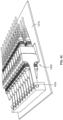
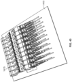
- FIGS. 20-22 another example of a patch panel 400 that is formed of a plurality of pivotal termination arrangements 420 having features similar to those shown in FIGS. 1-19 is illustrated.
- the patch panel 400 defined by the horizontally stacked termination arrangements 420 is shown in FIGS. 21 and 22 as being mounted in a telecommunications drawer 410.
- the depicted telecommunications drawer 410 may form part of a distribution element, such as a sliding chassis type element.
- Such elements may be configured for connecting patch cables entering one side of the element to an incoming cable, such as a distribution cable or a feeder cable entering an opposite side of the element. Examples of such distribution elements are described in PCT Publication Nos. WO 2014/118227 ; WO 2014/207210 ; and WO 2016/012550 .
- the patch panel 400 is shown as mounted in the drawer 410 in combination with an optical splice arrangement 430.
- the splice arrangement 430 is illustrated in the form of a plurality of pivotable splice trays 432 mounted in a stacked arrangement toward a rear 402 of the drawer 410.
- the first fibers and/or the second fibers can be routed to the depicted patch panel 400 from the optical splice arrangement 430.
- unconnectorized ends of the first fibers and/or the second fibers may spliced to distribution cables at the optical splice arrangement 430.
- connectorized ends of the first fibers and/or second fibers are routed within the drawer 410 to adapters 450 of the patch panel 400.
- the adapters 450 of the patch panel 400 align and optically couple the connectorized ends of the first fibers with the connectorized ends of the second fibers.
- the optical splice arrangement 430 also may provide anchoring for the distribution cables.
- the patch panel 400 is formed from the pivotable termination arrangements 420.
- the ability to pivot the termination arrangements 420 allows adjacent termination arrangements 420 to be pivoted away from a selected termination arrangement 420 to enhance connector access or optical adapter port access at the selected termination arrangement 420.
- each termination arrangement 420 includes an adapter holder portion 425 at a second end 422 and a fiber management portion 460 at a first end 421, where the adapter holder and fiber management portions 425, 460 are separated by a support member 423.
- the adapter holder portion 425 of each termination arrangement 420 is configured to receive and hold at least one optical adapter 450.
- the adapter holder portion 425 may receive and hold multiple optical adapters 450 (e.g., two, three, four, six, eight, ten, twelve, sixteen, etc.).
- the adapter holder portion 425 can be configured to hold simplex, duplex, or quad adapters 450.
- the depicted adapters 450 are of the SC type, the inventive aspects of the present disclosure are fully applicable to any format adapter, such as SC, LC, MPO, etc.
- each termination arrangement 420 is defined by bend radius limiters 461, a retention wall 469, and a retention tab 462 extending from the retention wall 469.
- the bend radius limiters 461 in combination with the retention walls 469 define cable channels 465 for routing optical cabling within the depicted telecommunications drawer 410 to or from the splice trays 432.
- the termination arrangement 420 is configured to pivot about a pivot axis A that is along the Z-axis with respect to the drawer 410.
- the Z-axis is shown diagrammatically in FIG. 52 of the present application, along with the Y-axis and the X-axis, which will be referred to throughout the present specification.
- the termination arrangement 420 of FIGS. 20-22 may utilize a pin, hole, or other mounting structure 424 located at an underside of the support member 423 (i.e., at an opposite side of the support member from the adapter holder) to provide the pivotability for the termination arrangement 420.
- the pivot mounting structure 424 at the first end 421 of the support member 423, the pivot axis A of the termination arrangement 420 is spaced from the adapter holder portion 425.
- the adapters 450 (and any optical connectors received thereat) also are spaced from the pivot axis A. Spacing the adapters 450 from the pivot axis A increases the distance over which a selected termination arrangement 420 can be spaced from adjacent termination arrangements 420. Spacing the adapters 450 from the pivot axis A may also decrease strain on the cables routed through the patch panel 400. Sufficient cabling can extend between the pivot axis A and the adapter port to accommodate the rotational deflection of the port.
- the termination arrangements 420 can be mounted directly to the telecommunications drawer 410 (as opposed to a separate base as shown in the examples of FIGS. 1-19 ) for rotation relative thereto to enable pivoting of the termination arrangements 420.
- FIGS. 23 and 24 illustrate an embodiment of a patch panel 500 similar to that shown in FIGS. 20-22 that is mounted on a separate tray 511 that has the ability to hinge about the X-axis. While each termination element 520 of the patch panel 500 is able to pivot about the Z-axis to enhance connector access or optical adapter port access at the selected termination arrangement 520, the hingability of the tray 511 allows cleaning access. For example, a large cleaning probe can slide into an adapter opening from the front of the drawer 510 after the tray 511 has been hinged upwardly about the X-axis.
- FIGS. 25-27 illustrate another embodiment of a patch panel 600 that is a variation on the hingable tray concept of FIGS. 23 and 24 .
- each of the termination arrangements 620 are configured with a hinge 624 at a first end 621 of a support member 623 for providing cleaning access to individual adapter holder portions 625.
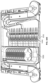
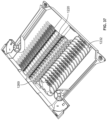
- FIGS. 34 and 35 illustrate a variation on the layout shown in FIGS. 32-33 with three splice towers 1130 provided at the side of the telecommunications drawer 1110.
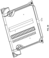
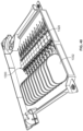
- FIGS. 36-38 illustrate a version of a layout similar to that shown in FIGS. 32-33 , however, providing a direct routing configuration between termination arrangements 1220 and individual splice trays 1232, where the termination arrangements 1220 stacked front to back are provided to correspond to given splice trays 1232 stacked front to back, limiting the ability to route fibers from any given termination arrangement 1220 to any given splice tray 1232.
- the termination arrangements 1220 shown in FIGS. 36-38 are similar in configuration to that shown in FIGS. 30 and 31 , having a cable retention wall 1269 at a first end 1221 of a support member 1223, adjacent a hinge 1224.
- the drawer 1210 is shown in an empty configuration in FIG. 38 .
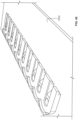
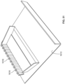
- FIGS. 41-44 illustrate an example of a patch panel 1400 where each termination arrangement 1420 not only allows hinged or pivotal movement for cleaning access but is also configured with a flexible support member 1423 for elastic deformation or flexing of the support member 1423 to enhance connector access or optical adapter port access.
- the support member 1423 extends from a side of an adapter holding portion 1425 and defines a pivot pin 1424 at a first end 1421 thereof.
- the pivot pin 1424 allows pivotability or hingability of the termination arrangement 1420 about the X or the Y axis (depending upon how the patch panel 1400 is arranged within a given telecommunications drawer).
- the support member 1423 of the termination arrangement 1420 allows flexing of the termination arrangement 1420 about the Z-axis, in a travel path that is perpendicular to the X and Y axes.
- the support member 1623 of the termination arrangement is flexible for elastic deformation thereof to enhance connector access or optical adapter port access, about an axis (either X or Y, depending upon how the patch panel is arranged within a given telecommunications drawer) that is perpendicular to the Z-axis.
- the example distribution element 1700 shown in FIGS. 53-57 utilizes a pair of frame members 1712 that are hingedly mounted in a stacked configuration.
- One of the frame members 1712 is shown in isolation in FIGS. 54-56 .
- the frame member 1712 includes a cable management insert 1710 that is configured for removable coupling thereto at a right side of the frame member 1712 and a splice insert 1701 that is positioned at a left side of the frame member 1712.
- the cable management insert 1710 shares a similar configuration and functionality with the inserts discussed in PCT Publication No. WO 2016/156611 .
- the cable management insert 1710 defines a generally planar configuration with a front end 1724, a rear end 1726, a right side 1728, and a left side 1729.
- the cable management insert includes a plurality of radius limiters 1732 (e.g., spools) that are arranged from the front end 1724 to the rear end 1726 in a stacked arrangement.
- the radius limiters 1732 are designed to provide cable paths of differing lengths depending upon where the radius limiters 1732 are positioned with respect to a patch or connection panel 1720.
- the cable management insert 1710 provides the advantage of being able to use similar (or same) length cables or pigtails extending from a fiber optic device that has been mounted to the element, even though each cable is patched at a different point on the patch panel 1720.
- the different radius limiters 1732 accomplish the purpose of adjusting for the different patching locations of the cables.
- the radius limiter 1732 of insert 1710 closest to the rear end 1726 of the insert 1710 defines a spool wall 1736 having a longer length than the rest of the radius limiters 1732 in the insert 1710.
- the wall 1736 of the rear-most radius limiter 1732 includes an angled straight portion 1735 that transitions into a curved portion 1737 as the wall 1736 extends from the rear end 1726 toward the front end 1724 of the cable management insert 1710.
- the front three radius limiters 1732 define spool walls 1736 having similar lengths to each other but shorter than that of the rear-most radius limiter 1732.
- Each of the radius limiters 1732 define retention fingers 1744 extending from the spool walls 1736 thereof for retaining the cables around the spools 1732.
- a right-most wall 1746 defined by the insert 1710 also includes retention fingers 1744 extending inwardly therefrom for keeping the cables within the insert 1710 as they are lead to the different radius limiters 1732.
- each of the front three radius limiters 1732 can have spool walls 1736 with differing lengths from each other, to provide for a finer adjustment/accommodation for the final patching location of the cables.
- the left side of the frame member 1712 includes a splice insert 1701 that is configured to receive a plurality of hingedly mounted splice trays 1730 in a stacked arrangement.
- the splice trays 1730 are mounted so as to be hinged along the Y-axis defined by the element as diagrammatically illustrated in FIG. 52 .
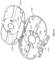
- One of the splice trays 1730 is illustrated in isolation in FIG. 57 .
- the fibers can be routed to/from the depicted patch panel 1720 utilizing the cable routing pattern shown in FIG. 56 , as well as the fibers incoming to and outgoing from the splice trays 1730. It should be noted that, although the patch panel 1720 illustrated in the example element 1700 in FIGS. 53-57 does not have pivotability or flexibility features of finger or cleaning access, such features may be incorporated into the depicted patch panel 1720 in other examples.
- the adapter holder portion 1825 is configured with a hinge pin 1824 that is receivable by a hinge receiver 1801 located at a first end 1821 of the support member 1823 for allowing the pivotal motion.
- the pivotal motion of the adapter holder portion 1825 may be between 0 and 45 degrees. Other travel ranges may be implemented depending upon the need.
- FIGS. 69-71 a version of an adapter holder 1825 that is configured to hold two LC Duplex adapters 1850 is shown.
- FIG. 72 a version of an adapter holder 1825 that is configured to hold four SC adapters 1850 is shown.
- FIG. 76 illustrates some of the different formats, numbers, and layouts of the adapters 1850 that can be used on the termination arrangements of the present disclosure.
- FIG. 68 illustrates an example of a packaging sequence where twelve termination arrangements 1820 according to a customer's color-code have been provided for placement within a telecommunications drawer such as the drawer 1810. As shown, numbering labels 1805 may be provided on the adapter holder portions 1825 for identification purposes.
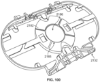
- the support member 2123 has a double-wide configuration for supporting two splice trays 2132 that are integrally incorporated onto the support member 2123 and two adapter holder portions 2125 that are separately pivotable with respect to the support member 2123.
- the support member 2123 is shown in isolation in FIG. 90 .
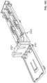
- One of the splice trays 2132 is illustrated in isolation in an exploded configuration in FIG. 92 .
- the tab 2104 prevents or limits the retainer 2124 from being pulled past 20 degrees, which, in most examples, has proven to be an optimal angle to provide enough finger access at both sides of an adapter supported by the adapter holder portion 2125 for cleaning and inspection and minimize the amount of fiber/cable displacement or pull.
- Each adapter holder portion 2125 is also configured with a rib 2106 on each side thereof that is configured to fit within a pocket 2107 defined adjacent the hinge receiver 2101 on each side of the support member 2123.
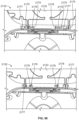
- the rib 2106 is designed to limit the deflection of the snap hooks 2102 defining the hinge receivers 2101 once the hinge retainers 2124 have been snap-fit into the hinge receivers 2101.
- the rib 2106 also absorbs any deflection forces applied on the snap hooks 2102.
- FIG. 84 is a close-up view of the termination arrangement 2120 with one of the adapter holder portions 2125 shown in a pivoted position.
- FIG. 85 is a close-up view of the termination arrangement 2120 of FIG. 80 with the adapter holder portions 2125 shown in a non-pivoted neutral position.
- FIG. 86 illustrates a close-up view of the hinge retainer 2124 of an adapter holder portion 2125 of the termination arrangement 2120 of FIG. 80 , with one of the adapter holder portions 2125 shown in a pivoted position.
- FIG. 87 illustrates a close-up view of the hinge retainer 2124 of FIG. 86 when the adapter holder portions 2125 are at a non-pivoted neutral position.
- FIG. 88 is a close-up front perspective view of a plurality of the termination arrangements 2120 of FIG. 80 with one of the adapter holder portions 2125 shown in a pivoted position.
- the rib 2106 allows enough spacing for the snap hooks 2102 to deflect during removal or insertion of the hinge retainers 2124.
- the adapter holder portion 2125 is shown in a neutral position in FIG. 87 where the rib 2106 blocks any deflection of the snap hooks 2102.
- the adapter holder portion 2125 also defines a cable management structure 2108 adjacent the hinge retainer 2124.
- the cable management structure 2108 is configured to keep cables/fibers coming from each of the adapters downward toward the hinge point and through a cable channel 2109 that is defined between the hinge retainers 2124 on each side of the adapter holder portion 2125. In this manner, the cables/fibers are generally at the same height as the pivot axis, limiting the amount of pull or displacement on the cables/fibers.
- the fibers are led by cable management structures 2160 on the support member 2123 to the trays 2132 for a splice operation, similar to the termination arrangements discussed above.
- the cable management structures 2160 are positioned at a cable channel 2165 that is defined on the support member 2123 for routing the fibers all the way from the adapters to a second end 2122 of the support member 2123.
- Fibers spliced at the trays 2132 that exit the termination arrangement 2120 are managed out of the support member 2123 by further cable management structures 2161 that are positioned at the second end 2122 of the support member 2123.
- the cable management structures 2161 allow the fibers to lead to a right or left side from the splice trays 2132 as shown.
- FIG. 82 illustrates the termination arrangement 2120 in a pre-terminated configuration with cabling at a factory level ready for installation.
- the support member 2123 in the depicted embodiment, is configured to be fixedly mounted to a telecommunications fixture such as a telecommunications drawer 1810 (as shown in FIGS. 64-65 ) similar to that illustrated for the termination arrangements shown in FIGS. 20-79 .
- Each support member 2123 may include a mounting structure such as a boss or a pin for mounting to mating openings defined on the telecommunications fixture.
- the support member 2123 is designed at the front end with a lower snap 2110 and an upper snap 2111. Both the lower and upper snaps 2110, 2111 cooperate with hook portions 2112 defined on the adapter holder portion 2125 to keep the adapter holding portion 2125 at about 0 degrees (neutral, non-pivoted position) and about 20 degrees (pivoted position), respectively. As shown in FIG. 84 , the hooks 2112 also abut a lip portion 2113 defined at the front end to prevent the adapter holder portion 2125 from being pulled to more than 20 degrees, where the lip 2113 acts as a positive stop.
- the support member 2523 of termination arrangement 2520 includes snaps 2510 for keeping the adapter holder portions 2525 at a non-pivoted neutral position.
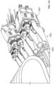
- FIGS. 107-108 illustrate a close-up view of the adapter holder portions 2525 of the termination arrangement 2520.
- FIG. 109 illustrates one of the adapter holder portions 2525 of the termination arrangement 2520 in isolation.
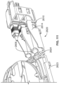
- FIGS. 115-119 a number of variations on the hinge retainer/pin parts of an adapter holder portion 2680 are shown.
- the types of hinge retainers that are illustrated in FIGS. 115-119 are all designed to provide self-biasing for returning pivoted adapter holder portions 2680 to a neutral position.
- the version of the hinge retainer 2681 illustrated in FIG. 115 includes bars 2682 that are configured to fit mating receptacles within a hinge receiver.
- the bars 2682 are connected to a hinge structure 2683 with arms 2684 that become elastically deformed during pivotal rotation of adapter holder portions 2680.
- the arms 2684 that get elastically deformed provide a bias force to return the adapter holder portions 2680 back to a neutral position.
- FIG. 116 illustrates a variation where bars 2685 that are configured to fit mating receptacles in a hinge receiver are integrally connected to or molded with a hinge structure 2686. Portions 2687 that integrally connect the bars 2685 to the rest of the hinge structure 2686 are designed to be elastically deformed during pivotal rotation of the adapter holder portions 2680. The portions 2687 that get elastically deformed provide a bias force to return the adapter holder portions 2680 back to a neutral position.
- FIG. 117 generally illustrates a version of a hinge retainer 2688 where a center pivot pin 2689 is connected to a hub 2690 of a hinge structure 2691 with elastically deformable spokes 2692.
- FIG. 118 illustrates a version where a pin 2693 is non-circular and is connected via two elastically deformable spokes 2694, and
- FIG. 119 illustrates a version with three elastically deformable spokes 2695.
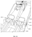
- FIGS. 120 and 121 another example of a termination arrangement 2720 having certain features that are similar to those shown on the termination arrangement of FIG. 80 is illustrated. Similar to the termination arrangement illustrated in FIG. 80 , the termination arrangement 2720 also includes a support member 2723 that has a double-wide configuration for supporting two splice trays 2732 that are integrally incorporated onto the support member 2723 and two adapter holder portions 2725 that are separately pivotable with respect to the support member 2723 for access. However, the termination arrangement 2720, in contrast to the hinged adapter holder portions on the termination arrangement 2120 shown in FIG. 80 , utilizes removable and elastically flexible adapter holder portions 2725 that are similar in structure and function to those shown on the termination arrangement 2020 of FIGS. 77-79 .
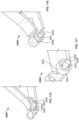
- FIGS. 122-124 illustrate another example of a termination arrangement 2820.
- the example termination arrangement 2820 is shown as utilizing a single-wide support member 2823, a splice tray 2832 that is integrally incorporated onto the support member 2823, and a single adapter holder portion 2825.
- the features shown are fully applicable to double-wide versions discussed above.
- the adapter holder portion 2825 of the termination arrangement 2820 is integrally formed or molded with and elastically flexible with respect to the support member 2823.
- FIG. 123 illustrates a side view of the termination arrangement 2820 showing a close-up of a flexible portion 2824 of the support member 2823 for pivoting the adapter holder portion 2825, where the flexible portion 2824 is provided with a reduced thickness 2801 to simulate a hinge.
- FIG. 124 illustrates a top view of the termination arrangement 2820 showing a reduced width 2802 of the support member to simulate a hinge and to facilitate the elastic flexing.
- a cable management structure 2808 is provided at the reduced thickness and width portions 2801, 2802 of the support member 2823.
- the cable management structure 2808 is designed to keep cables/fibers coming from each of the adapters down toward the hinge point and lead the fibers through a cable channel 2865 toward splice trays 2832.
- the cable management structure 2808 is designed to retain the cables/fibers close to the hinge point, generally around the same height as the pivot axis, to limit the amount of pull or displacement on the cables/fibers during pivotal movement of the adapter holder portion 2825.
- FIGS. 125-126 illustrate another example of a termination arrangement 2920 having certain features that are similar to those shown on the termination arrangement 2820 of FIGS. 122-124 .
- an adapter holder portion 2925 of the termination arrangement 2920 is integrally molded with and elastically flexible with respect to a support member 2923.
- a cable management structure 2908 is provided at a position that is set farther back from a reduced thickness portion 2901 that defines a hinge point. In this manner, the hinge point is positioned in the middle of the portion of the support member 2923 that holds the adapters and the cable management structure 2908, where these structures are supported by full thickness portions of the support member 2923.
- FIG. 127 illustrates yet another example of a termination arrangement 3020 having certain features that are similar to those shown on the termination arrangements 2820 and 2920.
- an adapter holder portion 3025 of the termination arrangement 3020 is integrally molded with and elastically flexible with respect to a support member 3023.
- the support member 3023 defines spaced-apart flex stop portions 3013 that are positioned on each side of a flex point.
- the flex stop portions 3013 are configured to abut each other to provide a hard stop when the adapter holder portion 3025 has been pivoted to a pre-specified angle.
- the pre-specified angle may be around 20 degrees as noted above.
- the adapter holder portion 3025 that is elastically pivotable with respect to the rest of the support member 3023 may also be provided with a stiffening rib 3014 for additional strength to this area.
- FIGS. 128-130 illustrate a variation on the adapter holder portion 3080 that can be mounted on termination arrangements such as those shown in FIGS. 80-114 .
- the adapter holder portion 3080 is designed to receive adapters 3085 in a vertical orientation, as opposed to a horizontal orientation shown in, for example, FIGS. 80-127 .
- FIG. 128 shows a side view of the adapter holder portion 3080 illustrating a gap 3081 that may be provided under a label plate 3082 for facilitating access.
- FIG. 129 shows the adapter holder portion 3080 from a bottom perspective view, illustrating a tab 3083 that might be provided at the bottom of the adapter holder portion 3080 that is configured to receive a latching clip 3084 that can be provided on the adapters 3085.
- the latching clip 3084 may be designed to be asymmetric for keeping right-hand and left-hand adapter versions separate and providing a keying function during insertion into the adapter holder portion 3080.
- the overall width of the adapter holder portion 3080, the support member, and thus the termination arrangement can be reduced.
- the overall width may be reduced by 3mm.
- the thickness of sidewalls 3086 of the adapter holder portions 3080 may have to be adjusted to accommodate latches 3087 of connectors 3088 being mounted to the adapters 3085 such that the latches 3087 of the sideway-mounted connectors 3088 do not extend outward past the sides of the adapter holder portions 3080 to create a snag issue.
- FIG. 131 illustrates another example of a termination arrangement 3120.
- the termination arrangement 3120 includes certain features that are similar to those shown on the termination arrangement 1820 of FIG. 58 of the present application.
- the termination arrangement 3120 includes a splice tray 3132 integrally incorporated onto a support member 3123 of the termination arrangement 3120, where an adapter holder portion 3125 is separately removable and pivotable with respect to the support member 3123.
- the adapter holder portion 3125 is configured to receive four adapters stacked in a horizontal orientation, similar to one of the versions shown in FIG. 76 .
- the support member 3123 of the termination arrangement 3120 is shown with a vertical divider wall 3121 that separates the pivoting adapter holder portion 3125 and a splice tray mounting area on the support member 3123. It should be noted that the height of such a divider wall 3121 may depend on the height of the adapter stack (and the number of adapters) used on the adapter holder portion 3125. The design of the support member 3123 including the width of fiber channels 3165 and the tray configurations and numbers thereof may also depend on the number of adapters provided on the adapter holder portion 3125.
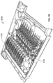
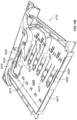
- FIGS. 132-152 generally illustrate another example embodiment of a termination arrangement 4120 having certain features that are examples of inventive aspects according to the principles of the present disclosure.
- the termination arrangement 4120 while similar in certain aspects to the termination arrangements of FIGS. 80-131 , includes features that are examples of inventive aspects the details of which will be discussed further.
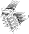
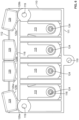
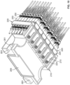
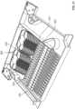
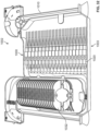
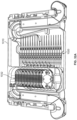
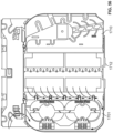
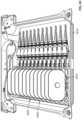
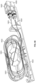
- a plurality of the termination arrangements 4120 are shown as being mounted in a telecommunications drawer 4110 similar to those shown in FIGS. 21-24 , 30-38 , 40 , 52-56 , 64 , and 65 . It should be noted that the drawer 4110 may form part of a telecommunications distribution element similar to those described in PCT Publication Nos. WO 2016/156611 and WO 2020/148296 .
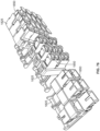
- the termination arrangements 4120 are shown as being provided in a stacked arrangement extending from a front 4001 of the drawer 4110 toward a back 4002 of the drawer 4110.
- the termination arrangement 4120 is similar in concept to the termination arrangement 2120 shown in FIGS. 80-101 in that at least one splice tray 4132 is integrally incorporated onto a support member 4123 of the termination arrangement 4120 and is hingable with respect to the termination arrangement 4120 along the X-axis (as illustrated diagrammatically in FIG. 52 ) and at least one adapter holder portion 4125 is removably mounted to the support member 4123 of the termination arrangement 4120 and is hingable with respect thereto and pivotable about the Y-axis for access (as illustrated diagrammatically in FIG. 52 ).
- the support member 4123 has a double-wide configuration for supporting two splice trays 4132 that are integrally incorporated onto the support member 4123 and two adapter holder portions 4125 that are separately pivotable with respect to the support member 4123.
- incoming fibers 4003 (e.g. 900 micron) to be spliced at the splice trays 4132 may enter the drawer 4110 at a left side 4004 of the drawer 4110. After being routed within a cable-entry channel 4005, around a radius-limiting spool 4006, the fibers 4003 are led toward each of the termination arrangements 4120 provided in a stacked arrangement within the drawer 4110 for splicing. As shown in FIG.
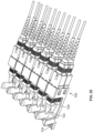
- each termination arrangement 4120 may include mounting features 4168 at a bottom 4212 of the support member 4123 for removable mounting to a telecommunications fixture such as the drawer 4110.
- the mounting features 4168 may include dove-tail shaped members 4126 along the bottom 4212 of the support member 4123 that are configured to cooperate with respective slots 4013 provided on the drawer 4110 for insertion and slidable locking of the termination arrangements 4120 to the drawer 4110.
- the cover 4014 and the drawer 4110 may include cooperating latching features for removable mounting of the cover 4014.
- the cover 4014 may include tabs 4015 that are inserted into recesses 4016 provided at front and rear walls 4017, 4018 of the drawer 4110 to provide a snap-fit interlock.
- each termination arrangement 4120 includes two splice trays 4132 for a total of twelve splice trays 4132 within the drawer 4110.
- Each splice tray 4132 provides fibers to two adapters 4085 (e.g., SC format) mounted in a stacked arrangement on the adapter holder portion 4125, providing a total of twenty-four connections within a drawer 4110. Since each depicted termination arrangement 4120 includes two hingedly attached adapter holder portions 4125, each termination arrangement 4120 provides for four connections.
- the fibers that are spliced at the exit side of the splice trays 4132 may be routed out of the drawer 4110 by being part of a pair of connectorized pigtails 4008 that are mated through the adapters 4085 on the adapter holder portions 4125 or may be provided as pass-through fibers 4009 that do not use the adapters 4085.
- FIGS. 133 and 134 illustrate the drawer 4110 with the cover 4014 mounted for protecting the splice trays 4132 of the termination arrangements 4120.
- FIG. 136 shows the drawer 4110 in an empty configuration illustrating an example cable routing for the incoming fibers 4003.
- FIG. 144 illustrates an example cable routing for the outgoing fibers 4007.
- FIG. 137 shows the drawer 4110 in a partially empty configuration to illustrate the slots 4013 that are configured to cooperate with the dove-tail shaped members 4126 of the termination arrangements 4120 for slidable locking to the drawer 4110.
- FIG. 138 shows the drawer 4110 in a completely empty configuration to illustrate some of the latching features on the drawer 4110 (e.g., recesses 4016) for removable mounting of the cover 4014.
- a fiber routing tool 4019 that may be provided as part of the drawer 4110.
- the fiber routing tool 4019 is a hand-held, elongate member that can be used to reach and manipulate fibers in certain areas within the drawer 4110 where finger access by a user may be limited.
- the fiber routing tool 4019 may be provided as part of the drawer 4110, removably snap-fit within a tool pocket 4020 located toward the back 4002 of the drawer 4110.
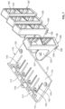
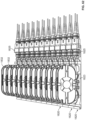
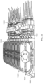
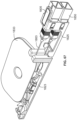
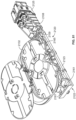
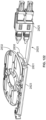
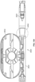
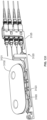
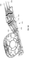
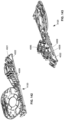
- FIGS. 139-143 and 145-152 one of the termination arrangements 4120 removed from the drawer 4110 is shown in isolation.
- the termination arrangement 4120 while similar in certain aspects to the termination arrangements 2120 of FIGS. 80-131 , includes certain features that are examples of inventive aspects according to the present disclosure.
- the termination arrangement 4120 includes a pair of splice trays 4132 integrally incorporated onto the support member 4123 of the termination arrangement 4120 that are hingable with respect to the termination arrangement 4120 along the X-axis.
- the termination arrangement 4120 also includes a pair of adapter holder portions 4125 that are removably mounted to the support member 4123 of the termination arrangement 4120 that are hingable with respect thereto and pivotable about the Y-axis for access.
- each termination arrangement 4120 within the drawer 4110 provides a double-wide configuration for supporting two splice trays 4132 that are integrally incorporated onto the support member 4123 and two adapter holder portions 4125 that are separately pivotable with respect to the support member 4123 for access.
- each hinge retainer 4124 is provided with a curved portion 4103 for allowing pivotal motion within the hinge receiver 4101. And, each hinge retainer 4124 is also provided with a secondary overpull protection tab 4104 that extends from the curved portion 4103.
- the secondary overpull protection tab 4104 is configured to abut internal vertical walls 4105 defined by the snap hooks 4102 of the hinge receiver 4101 to stop the retainer 4124 at a pre-specified pivoted angle.
- the secondary overpull protection tab 4104 is designed to abut the snap hook 4102 when the adapter holder portion 4125 has been pivoted about 20 degrees from the horizontal.
- Each adapter holder portion 4125 is also configured with a rib 4106 on each side thereof that is configured to fit within a pocket 4107 defined adjacent the hinge receiver 4101 on each side of the support member 4123.
- the rib 4106 is designed to limit the deflection of the snap hooks 4102 defining the hinge receivers 4101 once the hinge retainers 4124 have been snap-fit into the hinge receivers 4101.
- the rib 4106 also absorbs any deflection forces applied on the snap hooks 4102.
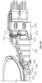
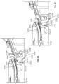
- FIG. 143 illustrates one of the termination arrangements 4120 with one of the adapter holder portions 4125 shown in a pivoted position.
- the rib 4106 allows enough spacing for the snap hooks 4102 to deflect during removal or insertion of the hinge retainers 4124.
- the adapter holder portion 4125 also defines a cable management structure 4108 adjacent the hinge retainer 4124.
- the cable management structure 4108 is configured to keep cables/fibers coming from each of the adapters downward toward the hinge point and through a cable channel 4109 that is defined between the hinge retainers 4124 on each side of the adapter holder portion 4125. In this manner, the cables/fibers 4008 are generally at the same height as the pivot axis, limiting the amount of pull or displacement on the cables/fibers 4008.
- the cable management structure 4108 is configured to allow cables/fibers 4008 to come in under the structure from only one side, which can provide extra side protection and retention for the cables.
- the support member 4123 in the depicted embodiment, is configured to be fixedly mounted to the drawer 4110 as noted above.
- the support member 4123 is designed adjacent the adapter holder portion 4125 with a lower snap 4000 and an upper snap 4111. Both the lower and upper snaps 4000, 4111 cooperate with hook portions 4112 defined on the adapter holder portion 4125 to keep the adapter holding portion 4125 at about 0 degrees (neutral, non-pivoted position) and about 20 degrees (pivoted position), respectively. As shown in FIG. 143 , the hooks 4112 also abut a lip portion 4113 to prevent the adapter holder portion 4125 from being pulled to more than 20 degrees, where the lip 4113 acts as a positive stop.
- each splice tray 4132 defines a hinge retainer 4115 that has a center rounded portion 4116 and keyed side portions 4117 defining a flat 4118.
- the hinge retainer 4115 is configured to be snap-fit into a hinge receiver 4119 defined on the support member 4123.
- the hinge receiver 4119 similar to the hinge retainer 4115 of each splice tray 4132, defines a center portion 4170 with spaced-apart elastic hooks 4171 and two side portions 4172 that are keyed for receiving the keyed side portions 4117 of the hinge retainer 4115.
- a given splice tray 4132 has to be oriented about 90 degrees from the horizontal when being coupled to the support member 4123.
- the center rounded portion 4116 of the hinge retainer 4115 is simply clicked into the center portion 4170 of the hinge receiver 4119 while the flats 4118 defined on the side portions 4117 of the hinge retainer 4115 have to be aligned with matching openings 4173 defined on the side portions 4172 of the hinge receiver 4119 during insertion.
- the hinge retainer 4115 of the splice trays 4132 and the hinge receivers 4119 of the support members 4123 are configured such that the splice trays 4132 generally lie at an angle of about 15 degrees to the horizontal when brought to a flat position. In this manner, the splice trays 4132 can lie flatter than those shown in FIGS. 80-101 , which allows each splice tray 4132 to be provided increased in size as compared to the trays discussed above and which allows a single large cover 4014 to be placed over the splice trays 4132 for protection.
- each splice tray 4132 due to its larger size, can provide an R30 bend radius versus, for example, an R20 bend radius provided in the earlier examples.
- the fibers that are spliced at the exit side of the splice trays 4132 may be provided as pass-through fibers 4009 that do not use the adapters 4085 of the adapter holder portions 4125.
- one or more of the adapters 4085 at the adapter holder portion 4125 of the termination arrangement 4120 can be replaced by other devices such as, for example, a cable termination unit (CTU) 4021.
- the CTU 4021 may also be referred to as a cable strength member fixation device.
- An example of this configuration is shown for the termination arrangement 2120 in FIG. 101 where a CTU 2187 has been provided in place of an adapter 2085 within the adapter holder portion 2125.
- the types of devices that can provide the pass-through option can be selected depending upon the desired connectivity.
- the inventive aspects of the termination arrangement 4120 provide a pass-through option for direct splicing without replacement of the adapters 4085 mounted at the adapter holder portion 4125 as shown in FIGS. 139-152 .
- the support member 4123 of the termination arrangement 4120 defines a pair of CTU mounts 4022 adjacent a front end 4023 of the support member 4123, in front of and spaced away from the pivotable adapter holder portions 4125.
- Each CTU mount 4022 is configured to removably receive a pair of CTU's 4021 while allowing the adapters 4085 to remain on the pivotable adapter holders 4125.
- adapters 4085 are not going to be used for mating a pair of connectorized pigtails 4008 and if a direct pass-through is going to be implemented via the CTU's 4021, connectors can simply be removed from the adapters 4085 while leaving the adapters 4085 mounted, and optical fiber(s) 4009 that have been spliced at the splice tray(s) 4132 can be routed directly to the CTU's 4021.
- each CTU mount 4022 is configured to mount two CTU's 4021 to match the number of adapters 4085 on a respective adapter holder portion 4125.
- the support member 4123 defines a pair of cable channels 4024 that are positioned underneath the pivotable adapter holder portions 4125 for accommodating the fibers 4009 that are directly routed to the CTU's 4021 adjacent the front 4023 of the support member 4123.
- the channels 4024 may be provided as cut-outs 4025 in the support member 4123.
- the support member 4123 may include cable retention fingers 4026 for keeping the pass-through fibers 4009 within the cutouts 4025 as shown. In this manner, the pass-through fibers 4009 can be routed directly under the adapter holder portions 4125 without interfering with the positioning or the function of the adapter holder portions 4125.
- the mounting slots 4013 within the drawer 4110 are provided at recessed areas 4027 as seen in FIGS. 137 and 138 .
- Each recessed area 4027 is flanked by a pair of walls 4028.
- the dove-tail shaped mounting features 4126 of the termination arrangements 4120 and the walls 4028 are configured such that a certain amount of space is provided between a bottom surface of the support members 4123 and a floor 4029 of the drawer 4110 to accommodate the pass-through fibers 4009 that are in the channels 4024.
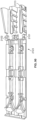
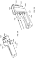
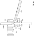
- FIGS. 145-147 illustrate further details of the CTU mounts 4022 and the removable mounting of the CTU's 4021 to the termination arrangement 4120.
- each CTU mount 4022 defines a pair of vertical flanges 4030 that are configured to slide within a pair of notches 4031 on opposite sides of the CTU 4021 when vertically receiving the CTU's 4021.
- a pocket 4032 is provided adjacent a bottom side of each CTU mount 4022 for accommodating a pin 4033 that protrudes from a bottom 4034 of each CTU 4021.
- the pins 4033 may cooperate with openings 4035 provided on top 4036 of each CTU 4021 for vertically aligning and stacking the CTU's 4021 in a locked manner.
- the flanges 4030 cooperate with the notches 4031 to limit axial movement of the CTU's 4021, and, therefore, axial movement of any cabling terminated to the CTU's 4021, as will be discussed in further detail below.
- FIG. 147 A cross-sectional view bisecting the CTU's 4021 is shown in FIG. 147 to illustrate the cooperatively-mating parts.
- FIGS. 148-152 the use of the depicted CTU's 4021 in providing termination of the pass-through cables/fibers 4009 so as to provide strength-member fixation is shown.
Landscapes
- Physics & Mathematics (AREA)
- General Physics & Mathematics (AREA)
- Optics & Photonics (AREA)
- Light Guides In General And Applications Therefor (AREA)
- Mechanical Coupling Of Light Guides (AREA)
Claims (11)
- Agencement de terminaison (4120) configuré pour le montage sur un montage de télécommunications (4110), l'agencement de terminaison (4120) comprenant :un organe support (4123) s'étendant entre des première et deuxième extrémités opposées, l'organe support (4123) comportant des éléments de montage (4168)pour le montage sur le montage de télécommunications (4110) ;au moins un plateau d'épissure (4132) fixé à l'organe support (4123) ;au moins un porte-adaptateur (4125) monté de manière amovible sur l'organe support (4123), le porte-adaptateur (4125) étant structuré pour maintenir au moins un adaptateur optique (4085) ; etau moins un dispositif de fixation d'organe de renfort de câble (4021) monté sur l'organe support (4123), dans lequel l'au moins un porte-adaptateur (4125) est positionné entre l'au moins un plateau d'épissure (4132) et l'au moins un dispositif de fixation d'organe de renfort de câble (4021), dans lequel l'organe support (4123) est configuré de telle sorte qu'une fibre optique (4009) épissée au sein de l'au moins un plateau d'épissure (4132) peut se terminer vers un premier connecteur pour être accouplée à un deuxième connecteur par l'intermédiaire de l'au moins un adaptateur optique (4085), dans lequel l'organe support (4123) est également configuré de telle sorte qu'une fibre optique (4009) épissée au sein de l'au moins un plateau d'épissure (4132) peut être directement acheminée vers l'au moins un dispositif de fixation d'organe de renfort de câble (4021) sans retirer un adaptateur (4085) de l'au moins un porte-adaptateur (4125), le dispositif de fixation d'organe de renfort de câble (4021) étant configuré pour serrer un organe de renfort (4044) d'un câble à fibre optique portant la fibre optique (4009) acheminée directement depuis le plateau d'épissure (4132) de sorte que le dispositif de fixation d'organe de renfort de câble (4021) absorbe les forces de traction agissant sur le câble à fibre optique qui se termine par l'intermédiaire de l'agencement de terminaison (4120), dans lequel l'organe support (4123) définit un canal (4024) positionné sous l'au moins un porte-adaptateur (4125) pour acheminer directement une fibre optique (4009) épissée au sein de l'au moins un plateau d'épissure (4132) vers l'au moins un dispositif de fixation d'organe de renfort de câble (4021) sans retirer un adaptateur (4085) de l'au moins un porte-adaptateur (4125).
- Agencement de terminaison (4120) selon la revendication 1, dans lequel l'au moins un porte-adaptateur (4125) est monté de manière mobile sur l'organe support (4123), dans lequel le mouvement du porte-adaptateur (4125) par rapport à l'organe support (4123) permet à l'au moins un adaptateur optique (4085) de s'éloigner du montage de télécommunications (4110) pour un accès.
- Agencement de terminaison (4120) selon la revendication 2, dans lequel l'au moins un porte-adaptateur (4125) est fixé de manière pivotante à l'organe support (4123) par l'intermédiaire d'un agencement de charnière (4115, 4119).
- Agencement de terminaison (4120) selon la revendication 1, dans lequel l'au moins un plateau d'épissure (4132) est monté de manière mobile sur l'organe support (4123).
- Agencement de terminaison (4120) selon la revendication 4, dans lequel l'au moins un plateau d'épissure (4132) est fixé de manière pivotante à l'organe support (4123).
- Agencement de terminaison (4120) selon la revendication 5, dans lequel l'au moins un porte-adaptateur (4125) est également fixé de manière pivotante à l'organe support (4123) de telle sorte que le plateau d'épissure (4132) et le porte-adaptateur (4125) pivotent autour d'axes perpendiculaires.
- Agencement de terminaison (4120) selon la revendication 1, dans lequel le porte-adaptateur (4125) est structuré pour maintenir une pluralité d'adaptateurs optiques (4085) en un empilement.
- Agencement de terminaison (4120) selon la revendication 1, dans lequel le porte-adaptateur (4125) est configuré pour maintenir un adaptateur optique (4085) de format SC ou LC.
- Agencement de terminaison (4120) selon la revendication 1, dans lequel l'agencement de terminaison (4120) comporte un nombre égal de dispositifs de fixation d'organe de renfort de câble (4021) et d'adaptateurs optiques (4085).
- Agencement de terminaison (4120) selon la revendication 1, comprenant en outre une pluralité d'adaptateurs optiques (4085) montés sur le porte-adaptateur (4125), chaque adaptateur optique (4085) définissant des ports se faisant face de manière opposée ayant des axes d'insertion de connecteur qui sont parallèles à l'organe support (4123).
- Montage de télécommunications (4110) comprenant :
une pluralité d'agencements de terminaison (4120) selon la revendication 1 montés sur le montage de télécommunications (4110) avec un verrouillage par encliquetage.
Applications Claiming Priority (1)
| Application Number | Priority Date | Filing Date | Title |
|---|---|---|---|
| US202063108709P | 2020-11-02 | 2020-11-02 |
Publications (2)
| Publication Number | Publication Date |
|---|---|
| EP3992683A1 EP3992683A1 (fr) | 2022-05-04 |
| EP3992683B1 true EP3992683B1 (fr) | 2025-07-09 |
Family
ID=78500420
Family Applications (1)
| Application Number | Title | Priority Date | Filing Date |
|---|---|---|---|
| EP21205835.8A Active EP3992683B1 (fr) | 2020-11-02 | 2021-11-01 | Agencement de répartition en épissure à adaptateurs mobiles |
Country Status (1)
| Country | Link |
|---|---|
| EP (1) | EP3992683B1 (fr) |
Families Citing this family (1)
| Publication number | Priority date | Publication date | Assignee | Title |
|---|---|---|---|---|
| EP4597188A1 (fr) * | 2024-01-31 | 2025-08-06 | CommScope Technologies LLC | Boîtier de branchement de fibre optique |
Family Cites Families (7)
| Publication number | Priority date | Publication date | Assignee | Title |
|---|---|---|---|---|
| NZ708968A (en) | 2013-01-29 | 2018-03-23 | CommScope Connectivity Belgium BVBA | Optical fiber distribution system |
| WO2014207210A1 (fr) | 2013-06-28 | 2014-12-31 | Tyco Electronics Raychem Bvba | Système de distribution de fibres optiques à guides de câbles étagés |
| EP3172902B1 (fr) | 2014-07-25 | 2018-06-27 | CommScope Connectivity Belgium BVBA | Éléments de distribution de télécommunication |
| US10261281B2 (en) | 2015-04-03 | 2019-04-16 | CommScope Connectivity Belgium BVBA | Telecommunications distribution elements |
| WO2018202812A2 (fr) | 2017-05-05 | 2018-11-08 | CommScope Connectivity Belgium BVBA | Enceinte à caractéristiques modulaires |
| US11422327B2 (en) * | 2018-02-13 | 2022-08-23 | Commscope Technologies Llc | Cable sealant arrangement for a sealed closure |
| EP3911987B1 (fr) | 2019-01-15 | 2023-08-09 | CommScope Connectivity Belgium BVBA | Agencement de répartition en épissure à adaptateurs mobiles |
-
2021
- 2021-11-01 EP EP21205835.8A patent/EP3992683B1/fr active Active
Also Published As
| Publication number | Publication date |
|---|---|
| EP3992683A1 (fr) | 2022-05-04 |
Similar Documents
| Publication | Publication Date | Title |
|---|---|---|
| EP3911987B1 (fr) | Agencement de répartition en épissure à adaptateurs mobiles | |
| US20260036778A1 (en) | Telecommunications module arrangements | |
| US12197025B2 (en) | Frame assemblies for optical fiber distribution elements | |
| US12197027B2 (en) | Frame assemblies for optical fiber distribution elements | |
| US12197026B2 (en) | Frame assemblies for optical fiber distribution elements | |
| US12189188B2 (en) | Frame assemblies for optical fiber distribution elements | |
| US12306451B2 (en) | Frame assemblies for optical fiber distribution elements | |
| US10585258B2 (en) | Bladed chassis systems and removable cassettes | |
| US12007615B2 (en) | Frame assemblies for optical fiber distribution elements | |
| EP3695259B1 (fr) | Plateau de télécommunications à fibres optiques à accessibilité et gestion améliorées | |
| US11947177B2 (en) | Frame assemblies for optical fiber distribution elements | |
| US20250189743A1 (en) | Cable termination units for optical fiber distribution elements | |
| US20210364721A1 (en) | Field repairable fiber optic cassette | |
| EP3992683A1 (fr) | Agencement de répartition en épissure à adaptateurs mobiles | |
| WO2020205554A1 (fr) | Interface pour connecter des composants de télécommunications | |
| EP4463728A1 (fr) | Agencement de répartition en épissure à adaptateurs mobiles | |
| WO2024192168A1 (fr) | Système de distribution de fibres optiques | |
| WO2022192670A1 (fr) | Composants pour systèmes à fibres optiques |
Legal Events
| Date | Code | Title | Description |
|---|---|---|---|
| PUAI | Public reference made under article 153(3) epc to a published international application that has entered the european phase |
Free format text: ORIGINAL CODE: 0009012 |
|
| STAA | Information on the status of an ep patent application or granted ep patent |
Free format text: STATUS: THE APPLICATION HAS BEEN PUBLISHED |
|
| AK | Designated contracting states |
Kind code of ref document: A1 Designated state(s): AL AT BE BG CH CY CZ DE DK EE ES FI FR GB GR HR HU IE IS IT LI LT LU LV MC MK MT NL NO PL PT RO RS SE SI SK SM TR |
|
| STAA | Information on the status of an ep patent application or granted ep patent |
Free format text: STATUS: REQUEST FOR EXAMINATION WAS MADE |
|
| 17P | Request for examination filed |
Effective date: 20221028 |
|
| RBV | Designated contracting states (corrected) |
Designated state(s): AL AT BE BG CH CY CZ DE DK EE ES FI FR GB GR HR HU IE IS IT LI LT LU LV MC MK MT NL NO PL PT RO RS SE SI SK SM TR |
|
| GRAP | Despatch of communication of intention to grant a patent |
Free format text: ORIGINAL CODE: EPIDOSNIGR1 |
|
| STAA | Information on the status of an ep patent application or granted ep patent |
Free format text: STATUS: GRANT OF PATENT IS INTENDED |
|
| INTG | Intention to grant announced |
Effective date: 20250203 |
|
| GRAS | Grant fee paid |
Free format text: ORIGINAL CODE: EPIDOSNIGR3 |
|
| GRAA | (expected) grant |
Free format text: ORIGINAL CODE: 0009210 |
|
| STAA | Information on the status of an ep patent application or granted ep patent |
Free format text: STATUS: THE PATENT HAS BEEN GRANTED |
|
| AK | Designated contracting states |
Kind code of ref document: B1 Designated state(s): AL AT BE BG CH CY CZ DE DK EE ES FI FR GB GR HR HU IE IS IT LI LT LU LV MC MK MT NL NO PL PT RO RS SE SI SK SM TR |
|
| REG | Reference to a national code |
Ref country code: GB Ref legal event code: FG4D |
|
| REG | Reference to a national code |
Ref country code: CH Ref legal event code: EP |
|
| REG | Reference to a national code |
Ref country code: IE Ref legal event code: FG4D |
|
| REG | Reference to a national code |
Ref country code: DE Ref legal event code: R096 Ref document number: 602021033699 Country of ref document: DE |
|
| REG | Reference to a national code |
Ref country code: NL Ref legal event code: MP Effective date: 20250709 |
|
| PG25 | Lapsed in a contracting state [announced via postgrant information from national office to epo] |
Ref country code: PT Free format text: LAPSE BECAUSE OF FAILURE TO SUBMIT A TRANSLATION OF THE DESCRIPTION OR TO PAY THE FEE WITHIN THE PRESCRIBED TIME-LIMIT Effective date: 20251110 |
|
| PG25 | Lapsed in a contracting state [announced via postgrant information from national office to epo] |
Ref country code: NL Free format text: LAPSE BECAUSE OF FAILURE TO SUBMIT A TRANSLATION OF THE DESCRIPTION OR TO PAY THE FEE WITHIN THE PRESCRIBED TIME-LIMIT Effective date: 20250709 |
|
| REG | Reference to a national code |
Ref country code: AT Ref legal event code: MK05 Ref document number: 1812336 Country of ref document: AT Kind code of ref document: T Effective date: 20250709 |
|
| PG25 | Lapsed in a contracting state [announced via postgrant information from national office to epo] |
Ref country code: IS Free format text: LAPSE BECAUSE OF FAILURE TO SUBMIT A TRANSLATION OF THE DESCRIPTION OR TO PAY THE FEE WITHIN THE PRESCRIBED TIME-LIMIT Effective date: 20251109 |
|
| PGFP | Annual fee paid to national office [announced via postgrant information from national office to epo] |
Ref country code: DE Payment date: 20251128 Year of fee payment: 5 |
|
| PGFP | Annual fee paid to national office [announced via postgrant information from national office to epo] |
Ref country code: GB Payment date: 20251127 Year of fee payment: 5 |
|
| PG25 | Lapsed in a contracting state [announced via postgrant information from national office to epo] |
Ref country code: NO Free format text: LAPSE BECAUSE OF FAILURE TO SUBMIT A TRANSLATION OF THE DESCRIPTION OR TO PAY THE FEE WITHIN THE PRESCRIBED TIME-LIMIT Effective date: 20251009 |
|
| REG | Reference to a national code |
Ref country code: LT Ref legal event code: MG9D |
|
| PG25 | Lapsed in a contracting state [announced via postgrant information from national office to epo] |
Ref country code: AT Free format text: LAPSE BECAUSE OF FAILURE TO SUBMIT A TRANSLATION OF THE DESCRIPTION OR TO PAY THE FEE WITHIN THE PRESCRIBED TIME-LIMIT Effective date: 20250709 |
|
| PG25 | Lapsed in a contracting state [announced via postgrant information from national office to epo] |
Ref country code: FI Free format text: LAPSE BECAUSE OF FAILURE TO SUBMIT A TRANSLATION OF THE DESCRIPTION OR TO PAY THE FEE WITHIN THE PRESCRIBED TIME-LIMIT Effective date: 20250709 |
|
| PG25 | Lapsed in a contracting state [announced via postgrant information from national office to epo] |
Ref country code: HR Free format text: LAPSE BECAUSE OF FAILURE TO SUBMIT A TRANSLATION OF THE DESCRIPTION OR TO PAY THE FEE WITHIN THE PRESCRIBED TIME-LIMIT Effective date: 20250709 |
|
| PG25 | Lapsed in a contracting state [announced via postgrant information from national office to epo] |
Ref country code: GR Free format text: LAPSE BECAUSE OF FAILURE TO SUBMIT A TRANSLATION OF THE DESCRIPTION OR TO PAY THE FEE WITHIN THE PRESCRIBED TIME-LIMIT Effective date: 20251010 |
|
| PG25 | Lapsed in a contracting state [announced via postgrant information from national office to epo] |
Ref country code: SE Free format text: LAPSE BECAUSE OF FAILURE TO SUBMIT A TRANSLATION OF THE DESCRIPTION OR TO PAY THE FEE WITHIN THE PRESCRIBED TIME-LIMIT Effective date: 20250709 |
|
| PG25 | Lapsed in a contracting state [announced via postgrant information from national office to epo] |
Ref country code: LV Free format text: LAPSE BECAUSE OF FAILURE TO SUBMIT A TRANSLATION OF THE DESCRIPTION OR TO PAY THE FEE WITHIN THE PRESCRIBED TIME-LIMIT Effective date: 20250709 |
|
| PG25 | Lapsed in a contracting state [announced via postgrant information from national office to epo] |
Ref country code: BG Free format text: LAPSE BECAUSE OF FAILURE TO SUBMIT A TRANSLATION OF THE DESCRIPTION OR TO PAY THE FEE WITHIN THE PRESCRIBED TIME-LIMIT Effective date: 20250709 Ref country code: PL Free format text: LAPSE BECAUSE OF FAILURE TO SUBMIT A TRANSLATION OF THE DESCRIPTION OR TO PAY THE FEE WITHIN THE PRESCRIBED TIME-LIMIT Effective date: 20250709 |
|
| PG25 | Lapsed in a contracting state [announced via postgrant information from national office to epo] |
Ref country code: RS Free format text: LAPSE BECAUSE OF FAILURE TO SUBMIT A TRANSLATION OF THE DESCRIPTION OR TO PAY THE FEE WITHIN THE PRESCRIBED TIME-LIMIT Effective date: 20251009 |
|
| PG25 | Lapsed in a contracting state [announced via postgrant information from national office to epo] |
Ref country code: ES Free format text: LAPSE BECAUSE OF FAILURE TO SUBMIT A TRANSLATION OF THE DESCRIPTION OR TO PAY THE FEE WITHIN THE PRESCRIBED TIME-LIMIT Effective date: 20250709 |
|
| PG25 | Lapsed in a contracting state [announced via postgrant information from national office to epo] |
Ref country code: RO Free format text: LAPSE BECAUSE OF FAILURE TO SUBMIT A TRANSLATION OF THE DESCRIPTION OR TO PAY THE FEE WITHIN THE PRESCRIBED TIME-LIMIT Effective date: 20250709 |
|
| PG25 | Lapsed in a contracting state [announced via postgrant information from national office to epo] |
Ref country code: SM Free format text: LAPSE BECAUSE OF FAILURE TO SUBMIT A TRANSLATION OF THE DESCRIPTION OR TO PAY THE FEE WITHIN THE PRESCRIBED TIME-LIMIT Effective date: 20250709 |
|
| PG25 | Lapsed in a contracting state [announced via postgrant information from national office to epo] |
Ref country code: DK Free format text: LAPSE BECAUSE OF FAILURE TO SUBMIT A TRANSLATION OF THE DESCRIPTION OR TO PAY THE FEE WITHIN THE PRESCRIBED TIME-LIMIT Effective date: 20250709 |
|
| PG25 | Lapsed in a contracting state [announced via postgrant information from national office to epo] |
Ref country code: IT Free format text: LAPSE BECAUSE OF FAILURE TO SUBMIT A TRANSLATION OF THE DESCRIPTION OR TO PAY THE FEE WITHIN THE PRESCRIBED TIME-LIMIT Effective date: 20250709 |
|
| PG25 | Lapsed in a contracting state [announced via postgrant information from national office to epo] |
Ref country code: CZ Free format text: LAPSE BECAUSE OF FAILURE TO SUBMIT A TRANSLATION OF THE DESCRIPTION OR TO PAY THE FEE WITHIN THE PRESCRIBED TIME-LIMIT Effective date: 20250709 |
|
| PG25 | Lapsed in a contracting state [announced via postgrant information from national office to epo] |
Ref country code: SK Free format text: LAPSE BECAUSE OF FAILURE TO SUBMIT A TRANSLATION OF THE DESCRIPTION OR TO PAY THE FEE WITHIN THE PRESCRIBED TIME-LIMIT Effective date: 20250709 Ref country code: EE Free format text: LAPSE BECAUSE OF FAILURE TO SUBMIT A TRANSLATION OF THE DESCRIPTION OR TO PAY THE FEE WITHIN THE PRESCRIBED TIME-LIMIT Effective date: 20250709 |
|
| PLBE | No opposition filed within time limit |
Free format text: ORIGINAL CODE: 0009261 |
|
| STAA | Information on the status of an ep patent application or granted ep patent |
Free format text: STATUS: NO OPPOSITION FILED WITHIN TIME LIMIT |