EP3992684B1 - Dispositif adaptateur permettant d'établir de manière mobile une connexion de guidage lumineux, système, ainsi que procédé - Google Patents
Dispositif adaptateur permettant d'établir de manière mobile une connexion de guidage lumineux, système, ainsi que procédé Download PDFInfo
- Publication number
- EP3992684B1 EP3992684B1 EP21204660.1A EP21204660A EP3992684B1 EP 3992684 B1 EP3992684 B1 EP 3992684B1 EP 21204660 A EP21204660 A EP 21204660A EP 3992684 B1 EP3992684 B1 EP 3992684B1
- Authority
- EP
- European Patent Office
- Prior art keywords
- connection
- network
- optical
- unit
- adapter device
- Prior art date
- Legal status (The legal status is an assumption and is not a legal conclusion. Google has not performed a legal analysis and makes no representation as to the accuracy of the status listed.)
- Active
Links
Images



Classifications
-
- G—PHYSICS
- G02—OPTICS
- G02B—OPTICAL ELEMENTS, SYSTEMS OR APPARATUS
- G02B6/00—Light guides; Structural details of arrangements comprising light guides and other optical elements, e.g. couplings
- G02B6/44—Mechanical structures for providing tensile strength and external protection for fibres, e.g. optical transmission cables
- G02B6/4439—Auxiliary devices
- G02B6/444—Systems or boxes with surplus lengths
- G02B6/4452—Distribution frames
-
- G—PHYSICS
- G02—OPTICS
- G02B—OPTICAL ELEMENTS, SYSTEMS OR APPARATUS
- G02B6/00—Light guides; Structural details of arrangements comprising light guides and other optical elements, e.g. couplings
- G02B6/24—Coupling light guides
- G02B6/36—Mechanical coupling means
- G02B6/38—Mechanical coupling means having fibre to fibre mating means
- G02B6/3807—Dismountable connectors, i.e. comprising plugs
- G02B6/381—Dismountable connectors, i.e. comprising plugs of the ferrule type, e.g. fibre ends embedded in ferrules, connecting a pair of fibres
- G02B6/3825—Dismountable connectors, i.e. comprising plugs of the ferrule type, e.g. fibre ends embedded in ferrules, connecting a pair of fibres with an intermediate part, e.g. adapter, receptacle, linking two plugs
-
- G—PHYSICS
- G02—OPTICS
- G02B—OPTICAL ELEMENTS, SYSTEMS OR APPARATUS
- G02B6/00—Light guides; Structural details of arrangements comprising light guides and other optical elements, e.g. couplings
- G02B6/44—Mechanical structures for providing tensile strength and external protection for fibres, e.g. optical transmission cables
- G02B6/4439—Auxiliary devices
- G02B6/444—Systems or boxes with surplus lengths
- G02B6/44528—Patch-cords; Connector arrangements in the system or in the box
- G02B6/44529—Optical means for identifying patch-cords
Definitions
- the invention relates to an adapter device for mobile establishment of a light-conducting connection of a first optical access point of an optical network, in particular in the form of a fiber optic network, for connecting a first network connection type to an optical connection port of a device for connecting a device connection type, a system with a device and an adapter device and a method for mobile establishment of a light-conducting connection of a first optical access point to a connection port.
- an external device in the form of a measuring device When maintaining fiber optic networks, such as FTTX networks, it is often necessary to connect an external device in the form of a measuring device to individual fibers of the fiber optic network in order to measure or check parameters of the respective fiber optic network.
- OTDR optical time domain reflection method
- a connector of an access point on the fiber optic network route can be different from a connector of an access point in a household. Since the measuring device usually only has one connection, adapter cables are usually required to connect the measuring device to the respective type of connector.
- an adapter device for establishing a light-conducting connection of a first optical access point of an optical network, in particular in the form of a fiber optic network, for connecting a first network connection type to an optical connection port of a device for connecting a device connection type.
- the adapter device has a network connection unit.
- the network connection unit further comprises a first network connection of the first Mains connection type for light-conducting connection to the first access point, and a second mains connection of a second mains connection type for light-conducting connection to a second optical access point.
- the adapter device also has a device connection unit with at least one device connection of the device connection type for light-conducting connection to the device.
- the adapter device also has a carrier unit on which the first and second mains connections and the device connection are arranged. The first and second mains connections are each light-conductingly connected to the device connection unit by at least one connecting path.
- Mobile establishment of the connection can be understood in particular to mean that the adapter device can be used in a mobile manner, i.e. preferably carried and/or moved between the optical access points.
- the adapter device is a mobile adapter device.
- the adapter device in particular the carrier unit, can be portable and/or movable, for example.
- the optical network can preferably be a network for optical data transmission, in particular in the form of an FTTX network.
- the optical network can be part of an infrastructure, in particular a public one.
- the first and second access points can form different access points to the same optical network or to different optical networks.
- the device can be, for example, a test and/or measuring device for maintaining the optical network.
- the optical connection connection can preferably be arranged on a device housing of the device.
- the first and second network connection types i.e., for example, also the first and second access points, differ from one another.
- the first and/or second access point and/or the connection port can each be formed by a connector.
- the first and second network connection types can differ, for example, in the shape of the connectors.
- connection types ie in particular the mains connection types and the device connection types
- a socket and a plug can be provided for each of the connection types, which are designed to be complementary to one another.
- the first access point has a plug and the first mains connection has a socket of the first mains connection type.
- the first access point and the first mains connection for example, have a socket of the first mains connection type and the connection between the first access point and the first mains connection can be established by a connecting means, e.g. in the form of a connecting cable, which has a plug of the first mains connection type at both ends.
- the device connection type preferably corresponds to a connection standard according to E2000.
- the connection standard can be provided, for example, with one connector or in a duplex version with two connectors.
- connection of the first network connection to the first access point and the connection of the second network connection to the second access point can be established directly or indirectly. If the first and/or second access point is designed to be flexible, the first and/or second network connection of the network connection unit can be designed to be connected directly to the first and/or second access point. However, it is also conceivable that the first and/or second network connection can be connected to the first and/or second access point by a connecting means.
- the mains connections and the device connection are optical connections in particular.
- the connecting path can, for example, comprise at least one optical waveguide in order to form a light-conducting connection between the first and second mains connections and the device connection unit.
- the mains connections and/or the device connection can be connected to optical fibers, in particular glass fibers, for conducting light.
- the connecting path can preferably be designed for bidirectional light conduction.
- the connecting path can advantageously form part of a lead length and/or a trailing length, in particular with a length of up to 20 m.
- the first and/or the second mains connection can be permanently connected to the device connection or to one device connection each.
- the device connection unit has an intermediate connection via which, in particular optionally, the first and/or second mains connection can be connected to the device connection.
- only one Device connection of the device unit is provided, which can optionally be connected to the connecting lines in a light-conducting manner.
- the carrier unit can be formed in one piece by a carrier body. It is also conceivable that the carrier unit is designed in a modular manner.
- the network connection unit can comprise several, in particular interchangeable, modules, each of which has at least one network connection of a different network connection type.
- the carrier unit is preferably designed in the form of a plate. This can enable the carrier unit to be manufactured cost-effectively. It is also conceivable that the carrier unit comprises a metal, preferably aluminum. This can enable high stability when changing location for maintenance of the optical network.
- the network connection unit has the first network connection for the first type of network connection for the connection to the first access point and the second network connection for the second type of network connection for the connection to the second access point.
- the adapter device thus simplifies the maintenance of the optical network, as the technician carrying out the maintenance work can use the adapter device for the two different networks.
- the carrier unit also allows the various network connections to be easily transported together.
- the device connection unit has a path extension for extending a light path of the connecting paths, preferably from the connecting paths to the device connection for connection to the device, in particular wherein the path extension is designed as an optical lead path and/or as an optical trailing path.
- the path extension can have an optical fiber that enables the light path to be extended.
- the path extension can, for example, be wound up on a second side of the carrier unit, in particular below the mains connections, in particular to facilitate transportability of the adapter device.
- the path extension can be connected or connectable to the first and/or second mains connection. In particular, it is conceivable that a path extension is assigned to each of the mains connections of the mains connection unit.
- the extension of the route can reduce measurement errors in the area of the device connection, particularly when carrying out an OTDR method.
- a measurement method for maintaining the optical network can also have a high level of accuracy in the area of the first network connection.
- the extension of the light path due to the extension of the route can preferably be greater than or equal to 100 m, particularly preferably greater than or equal to 1000 m.
- the line extension has an intermediate connection, preferably of the device connection type, by means of which the line extension can be selectively connected to one of the connecting lines, and/or that a device connection, i.e. in particular the device connection connected to the connecting line or another device connection that can be connected to the connecting line, is formed by an end connection of the line extension for the light-conducting connection to the device.
- the line extension can be replugged by the intermediate connection in order to connect the line extension to one of the mains connections.
- the intermediate connection can be connected to another device connection of the device connection unit.
- a device connection of the device connection unit that is connected to the first and/or second mains connection by the connecting line can be used selectively to connect to the intermediate connection and/or to connect to the device.
- the end connection of the line extension can be used to connect to the device if the device connection connected to the first and/or second mains connection serves as the end connection for the line extension.
- the line extension can thus be used selectively by simply replugging it.
- the intermediate connection can be connected to a device connection by a connecting means, preferably by an optical cable, in order to establish the connection to the first and/or second network connection.
- a portable housing in which the carrier unit is arranged, in particular wherein the housing is preferably made essentially or completely from a plastic.
- the plastic can be a polypropylene.
- the housing can protect the carrier unit and the optical components from environmental influences, in particular during transport.
- the carrier unit is preferably designed as a housing insert for the housing, in particular a modular one.
- the carrier unit can be designed to complement the housing and/or be fitted into the housing.
- the carrier unit can be attached to the housing, in particular screwed to the housing.
- the housing can have external dimensions of less than or equal to 500 x 400 x 250 mm, preferably less than or equal to 400 x 300 x 200 mm.
- the housing has metal components.
- the housing can have a locking unit by means of which the housing can be locked.
- the housing has a base element on which the carrier unit is arranged and a cover element which can be at least partially removed from the base element to access the carrier unit, in particular wherein the base element and the carrier unit form a cavity.
- the connecting section can be arranged at least partially in the cavity, preferably so that only the power connections and the device connection(s) are accessible from the outside.
- the cavity can be sealed so that unauthorized access can be subsequently proven.
- the cover element can be attached to the base element in an articulated manner.
- the housing can have a carrying handle.
- the housing can be designed as a case. This can make the adapter device very comfortable to carry, making it easier to carry the adapter device around.
- the housing preferably the cover element
- the accessories can be placed loosely in the storage compartment.
- the accessories can include, for example, additional connecting cables or other tools.
- the accessories can be secured, in particular fastened, in the storage compartment against falling out.
- the storage compartment can have a closable opening which prevents the accessories from falling out.
- the storage compartment can be designed to be flexible or rigid.
- the storage compartment can have a wall made of a textile and/or plastic.
- the storage compartment can advantageously be integrated into the cover element.
- the storage compartment is integrated into the base element, preferably at least partially or extends completely into the cavity.
- the storage compartment is designed as a housing insert and/or as a 3D printed part.
- the mains connections of the mains connection unit and/or the at least one device connection each have a detachable covering means for protection against environmental influences.
- all device connections can each have a detachable covering means.
- the covering means can prevent dust from entering.
- the covering means can be designed like a cap.
- the covering means can thus be removable when the respective mains connection or device connection is in use in order to expose the mains connection or device connection. This means that unused device connections and/or mains connections can continue to be protected from dust.
- the carrier unit can also advantageously have and/or form a storage area for storing the covering means. This means that the removed covering means can be collected so that they are not lost when the adapter device is in operation.
- an adapter device it is also conceivable in an adapter device according to the invention that several further network connections of different, further network connection types are provided on the carrier unit, each of the further network connections being connected to the device connection unit by a further connecting path.
- the network connection unit has two or more similar network connections for each network connection type.
- the network connections of the same network connection type can be arranged in pairs on the carrier unit.
- the group of network connection types comprising the first network connection type, the second network connection type and/or the further network connection types, can comprise at least one connection standard according to E2000, at least one connection standard according to DIN, at least one connection standard according to LC, in particular LC duplex, (lucent connector) and/or at least one connection standard according to SC, in particular SC duplex, (subscriber connector).
- the respective connection standard can be provided, for example, in a simple or duplex version.
- the first network connection type, the second network connection type and/or the further network connection types at least one Connection standards such as F-SMA, FC, ST, ESCON, MIC, Mini-SC, URM, MTRJ, MPO/MTP, M12 and/or TOSLINK.
- Connection standards such as F-SMA, FC, ST, ESCON, MIC, Mini-SC, URM, MTRJ, MPO/MTP, M12 and/or TOSLINK.
- the device connection unit has two or more device connections of the device connection type, with a connection line being provided from each of the mains connections of the mains connection unit to at least one of the device connections of the device connection unit.
- a connection line being provided from each of the mains connections of the mains connection unit to at least one of the device connections of the device connection unit.
- a light source preferably in the form of a laser light source
- the carrier unit for feeding light into the optical network
- the light source is connected to a light connection which is designed according to the device connection type, so that light from the light source can be transmitted via the light connection.
- the light source can be integrated into the light connection.
- the light source can be connected to electronics for operating the light source.
- the electronics can preferably be arranged in the cavity of the housing.
- the electronics can be connected to a switch which is arranged on the carrier unit. This means that the light source can be activated and/or deactivated.
- the light source is designed to emit laser light, in particular in the form of a red laser.
- Connected optical fibers can be illuminated by the light source, so that a simple continuity test is possible and/or any defects that may be present can be easily found. Because the light connection is designed according to the device connection type, a connection of the light source to the optical network can be achieved via the device connection unit and the network connection unit. The measuring device can be separated from the adapter device.
- an adapter device can be provided with a power supply unit for mobile power supply of the light source, in particular wherein the housing has an access opening for access to the power supply unit.
- the power supply unit can preferably comprise a power source, e.g. in the form of at least one battery. This makes it possible to supply power to the light source in a simple manner and thus enable mobile use.
- the access opening allows for easy battery replacement.
- the power supply unit can comprise a charging unit for charging the power supply unit with electrical energy.
- a rechargeable battery or accumulator can be provided to provide the energy to operate the light source.
- the charging unit can be accessible via the access opening, e.g. to connect a charging cable.
- the adapter device for powering the light source can have a cable connection for connection to a power grid.
- the carrier unit has a first side, on which the mains connections of the mains connection unit and the at least one device connection of the device connection unit are arranged, and a second side, on which the connecting lines and/or the light source are arranged.
- the mains connections of the mains connection unit and the at least one device connection of the device connection unit can be plugged into the carrier unit from the second side and protrude on the first side.
- the first side can in particular form a visible side that is visible when the cover element of the housing is opened.
- the connecting lines and/or the light source on the second side, these components can be protected from environmental influences and/or unintentional behavior of a user.
- the second side can face the cavity of the housing.
- the first side can face the cover element.
- the carrier unit is designed as an information carrier with information indicating operation of the adapter device, in particular wherein the information is introduced into the carrier unit as depressions.
- the information can in particular be information about the device connection type of the device connections and/or the Mains connection type of the respective mains connections.
- the information can be provided on the first side of the carrier unit.
- the recesses can be milled or lasered, for example. This can ensure that the information is easy to read even in environments with a high level of dust.
- a system comprising a device with an optical connection port for connecting a device connection type and an adapter device according to the invention for mobile production of a light-conducting connection of a first optical access point of an optical network, in particular in the form of a fiber optic network, for connecting a first network connection type to the connection port of the device.
- the device can be, for example, a measuring device, preferably for carrying out an optical time domain reflection method (OTDR).
- OTD optical time domain reflection method
- the optical network can thus be maintained in a simple manner, and the adapter device can then be taken to a second optical access point.
- the same connection of the measuring device to the adapter device can be used for different types of network connection. It is also conceivable that the first and/or second access point and/or the optical network is part of the system according to the invention.
- a method according to the invention brings with it the same advantages as have already been described in detail with reference to an adapter device according to the invention and/or a system according to the invention.
- a plug connector can be light-conductingly connected to the first access point and a first mains connection of the adapter device.
- the connection connection can be light-conductingly connected to a device connection of the adapter device. This makes it easy to decouple the device connection type from the mains connection type, in particular with the access point and the connection connection being connected to the adapter device independently of one another.
- Figure 1 shows a system according to the invention with an adapter device 1 according to the invention for mobile production of a light-conducting connection between an optical network 3 and a device 5 in a top view.
- the optical network 3 is part of a, in particular public, infrastructure for data transmission, preferably a fiber optic network.
- the device 5 is in particular a measuring device for maintaining the optical network 3.
- the optical network 3 has a first access point 2 for connecting a first optical network connection type 2.1.
- the device 5 has an optical connection port 4 for connecting a device connection type 4.1.
- the first access point 2 itself is therefore of the first network connection type 2.1 and the connection port 4 is of the device connection type 4.1, with the first network connection type 2.1 and the device connection type 4.1 differing in particular.
- a second optical access point 6 of a second network connection type 2.2 is shown, to which the device 5 can also be connected for maintenance.
- the first and second network connection types 2.1, 2.2 differ, for example in that different standards of connectors are provided.
- the second access point 6 can form a further access point of the same optical network 3 or of a further optical network 3. Both network connection types 2.1, 2.2 can be connected to the connection port 4 of the device 5 using the adapter device 1.
- the adapter device 1 has a network connection unit 10 with several network connections 11, 12, 13 for connecting different network connection types 2.1, 2.2, 2.3.
- a first network connection 11, which is designed according to the first network connection type 2.1, and a second network connection 12, which is designed according to the second network connection type 2.2, are provided.
- several further network connections 13 of different, further network connection types 2.3 are arranged on the carrier unit 30.
- the network connections 11, 12, 13 are preferably arranged in pairs with similar network connections 11, 12, 13.
- the adapter device 1 can be connected directly to the first access point 2 via the first network connection 11 if the first access point 2 has, for example, a flexible connection means 16.
- a flexible connection means 16 can be provided which has a plug or a socket of the first network connection type 2.1 to connect the first access point 2 to the first network connection 11 of the adapter device 1.
- the adapter device 1 has a device connection unit 20 with several device connections 21, which are designed according to the device connection type 4.1.
- Each of the network connections 11, 12, 13 is connected to the device connection unit 20 in a light-conducting manner by a connecting path 14.
- each of the network connections 11, 12, 13 is assigned a device connection 21.
- the connecting paths 14 in particular comprise an optical connection.
- the connecting paths 14 can each comprise at least one optical fiber, which connects each network connection 11, 12, 13 to one of the device connections 21. Because the device connections 21 are designed according to the device connection type 4.1, the device 5 can be connected directly to one of the device connections 21 if the connection connection 4 of the device 5 has, for example, a flexible connecting means 16.
- a flexible connecting means 16 can be provided which has a plug or a socket of the device connection type 4.1 at both ends in order to connect the connection connection 4 to the respective device connection 21 of the adapter device 1. It is also conceivable that the connecting sections 14 at least partially have a flexible connecting means 16, e.g. in the form of a cable, on which the respective device connection 21 is arranged.
- the adapter device 1 to be connected to the device 5 in a simple manner.
- the user can use the first network connection 11 of the first network connection type 2.1 to connect to the optical network 3 and the device connection 21 of the device connection type 4.1 assigned to the first network connection 11 to connect to the device 5.
- both the device 5 and the network 3 can be connected to the adapter device 1 with their own connection type, i.e., for example, their own connection standard, so that adapter cables with different connection standards at both ends can be avoided.
- a method according to the invention for mobile establishment of a light-conducting connection of the first access point 2 with the connection port 4 of the device 5 comprises hence a connection 101 of the first access point 2 to the adapter device 1 and a connection 102 of the adapter device 1 to the connection port 4.
- the device connection unit 20 and the mains connection unit 10 are arranged on a carrier unit 30.
- the carrier unit 30 is designed in particular as a plate-like carrier body, preferably made of aluminum.
- the carrier unit 30 is designed in a modular manner in order to be able to provide different mains connections 11, 12, 13 for the adapter device 1.
- a housing 40 is also provided, into which the carrier unit 30 is inserted.
- the housing 40 is in the Figures 4 and 5 shown in cross-section.
- the housing 40 has a base element 41 and a cover element 42.
- the cover element 42 is in Figure 4 shown in a closed position and in Figure 5 in an open position. In the open position, the cover element 42 is at least partially removed from the base element 41, so that access to the carrier unit 30 and thus in particular to the power connection unit 10 and the device connection unit 20 is possible.
- the cover element 42 can be arranged in an articulated manner on the base element 41.
- the housing 40 also has a closure 45, by means of which an unintentional opening of the cover element 42 and/or unauthorized access to the carrier unit 30 can be prevented.
- the cover element 42 preferably also comprises a storage compartment 43, in which loose accessories can be accommodated. This means that other utensils carried along, such as tools or the like, can be carried along with the adapter device 1.
- the carrier unit 30 also has a first side 31, which faces the cover element 42 and on which the power connections 11, 12, 13 and the device connections 21 are accessible. Opposite the first side 31, the carrier unit 30 has a second side 32, which faces the base element 41.
- the carrier element 30 and the housing 40 also form a cavity 47 on a second side 32. For example, a cabling 34 of the connecting sections 14 and/or the section extensions 22 can be arranged in a protected manner in the cavity 47.
- the housing 40 can also have a carrying handle 46 for carrying the adapter device 1.
- the housing 40 further comprises fastening interfaces 48, preferably in the form of projections.
- the carrier unit 30 can be screwed to the housing 40 at the fastening interfaces 48, for example.
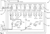
- the device connection unit 20 can have at least one line extension 22 for extending a light path of the connecting lines 14.
- the line extension 22 can be designed as an optical pre-run line 23 and/or as an optical post-run line 24.
- a connection of the first access point 2 to the device 5 via the line extension 22 is possible in Figure 2
- at least one path extension 22 is provided as an optical forward path 23 and at least one path extension 22 is provided as an optical follow-up path 24.
- the path extension 22 can have at least one optical fiber that extends the light path between the device 5 and the network 3.
- the light path can be extended by the path extension 22 by 100 m or more, particularly preferably by 1000 m or more.
- the path extension 22 comprises a device connection 21 of device connection type 4.1, which forms an end connection of the path extension 22 and can be connected to the device 5.
- the path extension 22 also comprises an intermediate connection 25 of device connection type 4.1, which can be connected to one of the further device connections 21 that are connected to the network connections 11, 12, 13 by the connecting paths 14.
- a connecting means 16 can be provided, which a user can replug as required.
- the line extension 22 can be selectively connected to each of the network connections 11, 12, 13 of the network connection unit 10.
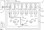
- the adapter device 1 has a light source 50, preferably in the form of a laser light source.
- Figure 3 shows a connection of the light source 50 to the network 3.
- the light source 50 is connected to a light connection 51 which is designed according to the device connection type 4.1.
- the light source 50 is designed according to Figure 3 via the first mains connection 11, a connecting line 14 assigned to the first mains connection 11 and the device connection 21 assigned to the connecting line 14 and the first mains connection 11.
- the light connection 51 By designing the light connection 51 according to the Device connection type 4.1 enables connection of one of the line extensions 22 and/or selection of one of the network connections 11, 12, 13 in a simple manner, in particular by means of the same connecting means 16.
- a switch 53 is also arranged on the carrier unit 30 for activating and/or deactivating the light source 50.
- Electronics (not shown) for operating the light source 50 are preferably arranged on the second side 32 of the carrier unit 30.
- a power supply unit 52 is also provided for the mobile power supply of the light source 50.
- the power supply unit 52 can comprise a battery and/or a rechargeable battery.
- the housing 40 also has an access opening 44 for access to the power supply unit 52.
- a battery replacement and/or a charging process for the power supply unit 52 can be made possible through the access opening 44.
- the carrier unit 30 is preferably designed as an information carrier with information to indicate an operation.
- the carrier unit 30 has recesses 33 that depict the information.
- the recesses 33 can be milled or lasered into a carrier body of the carrier unit 30.
- the recesses 33 can indicate the respective network connection type 2.1, 2.2, 2.3 of the network connections 11, 12, 13, the light source 50, the device connection type 4.1 and/or the line extensions 22.
- the recesses 33 particularly preferably depict the connecting lines 14 in order to be able to assign the device connections 21 to the network connections 11, 12, 13.
- Figure 6 also shows one of the device connections 21 with a detachable covering means 15 in the form of a dust cap.
- the covering means 15 can be removed for use of the device connection 21.
- all power connections 11, 12, 13, device connections 21 and the light connection 51 each have a covering means 15.
Landscapes
- Physics & Mathematics (AREA)
- General Physics & Mathematics (AREA)
- Optics & Photonics (AREA)
- Optical Couplings Of Light Guides (AREA)
Claims (15)
- Dispositif adaptateur (1) pour la réalisation mobile d'une liaison optique d'un premier point d'accès optique (2) d'un réseau optique (3), en particulier sous la forme d'un réseau de fibres optiques, pour le raccordement d'un premier type de raccordement au réseau (2.1) avec un raccordement de liaison optique (4) d'un appareil (5) pour le raccordement d'un type de raccordement d'appareil (4.1), présentantune unité de raccordement au réseau (10) avec un premier raccordement au réseau (11) du premier type de raccordement au réseau (2.1) pour la liaison par fibre optique avec le premier point d'accès (2) et un deuxième raccordement au réseau (12) d'un deuxième type de raccordement au réseau (2.2) pour la liaison par fibre optique avec un deuxième point d'accès optique (6), etune unité de raccordement d'appareil (20) avec au moins un raccordement d'appareil (21) du type de raccordement d'appareil (4.1) pour la liaison conductrice de lumière avec l'appareil (5), etune unité de support (30), sur laquelle sont disposés le premier et le deuxième raccordement au réseau (12) et le raccordement à l'appareil (4.1),la première et la deuxième raccordement au réseau (11, 12) étant reliées de manière photoconductrice à l'unité de raccordement d'appareil (20) par respectivement au moins une parcour de liaison (14),caractérisé en ce quele premier et le deuxième type de raccordement au réseau (11, 12) se distinguent l'un de l'autre.
- Dispositif adaptateur (1) selon la revendication 1,
caractérisé en ce que
l'unité de raccordement d'appareil (20) présente un prolongement de parcours (22) pour prolonger un parcours lumineux des parcours de liaison (14), en particulier le prolongement de parcours (22) étant conçu comme parcours optique d'aller (23) et/ou comme parcours optique de retour (24). - Dispositif adaptateur (1) selon la revendication 2,
caractérisé en ce que
le prolongement de parcour (22) présente un raccordement intermédiaire (25) par lequel le prolongement de parcour (22) peut être relié au choix à l'une des parcours de liaison (14), et/ou en ce qu'un raccordement d'appareil (21) est formé par un raccordement d'extrémité du prolongement de parcour (22) pour la liaison conductrice de lumière avec l'appareil (5). - Dispositif adaptateur (1) selon l'une des revendications précédentes,
caractérisé en ce qu'
il est prévu un boîtier portable (40) dans lequel est disposée l'unité de support (30), en particulier le boîtier (40) étant réalisé en une matière plastique. - Dispositif adaptateur (1) selon la revendication 4,
caractérisé en ce que
le boîtier (40) présente un élément de fond (41), sur lequel est disposée l'unité de support (30), et un élément de couvercle (42), qui peut être enlevé au moins partiellement de l'élément de fond (41) pour accéder à l'unité de support (30), en particulier l'élément de fond (41) et l'unité de support (30) formant un espace creux (47). - Dispositif adaptateur (1) selon l'une des revendications 4 ou 5,
caractérisé en ce que
le boîtier (40), en particulier l'élément de couvercle (42), présente au moins un compartiment de rangement (43) pour recevoir des accessoires détachés. - Dispositif adaptateur (1) selon l'une des revendications précédentes,
caractérisé en ce que
les raccordements au réseau (11, 12, 13) de l'unité de raccordement au réseau (10) et/ou l'au moins un raccordement d'appareil (21) présentent chacun un moyen de recouvrement (15) amovible pour la protection contre les influences de l'environnement. - Dispositif adaptateur (1) selon l'une des revendications précédentes,
caractérisé en ce que
plusieurs autres raccordements au réseau (13) de différents autres types de raccordement au réseau (2.3) sont prévus sur l'unité de support (30), chacun des autres raccordements au réseau (13) étant relié à l'unité de raccordement d'appareil (20) par respectivement une autre parcour de liaison (14). - Dispositif adaptateur (1) selon l'une des revendications précédentes,
caractérisé en ce que
l'unité de raccordement d'appareil (20) présente deux ou plusieurs raccordements d'appareil (21) du type de raccordement d'appareil (4.1), un parcour de liaison (14) étant prévu de chacun des raccordements de réseau (11, 12, 13) de l'unité de raccordement de réseau (10) vers au moins un des raccordements d'appareil (21) de l'unité de raccordement d'appareil (20). - Dispositif adaptateur (1) selon l'une des revendications précédentes,
caractérisé en ce qu'
une source de lumière (50), de préférence sous la forme d'une source de lumière laser, est prévue sur l'unité de support (30) pour alimenter en lumière le réseau optique (3), en particulier la source de lumière (50) étant reliée à un raccordement de lumière (51) qui est réalisé selon le type de raccordement d'appareil (4.1), de sorte que la lumière de la source de lumière (50) peut être transmise via le raccordement de lumière (51). - Dispositif adaptateur (1) selon la revendication 10,
caractérisé en ce qu'
une unité d'alimentation en énergie (52) est prévue pour l'alimentation en énergie mobile de la source lumineuse (50), en particulier le boîtier (40) présentant une ouverture d'accès (44) pour accéder à l'unité d'alimentation en énergie (52). - Dispositif adaptateur (1) selon l'une des revendications précédentes,
caractérisé en ce que
l'unité de support (30) présente un premier côté (31) sur lequel sont disposés les raccordements au réseau (11, 12, 13) de l'unité de raccordement au réseau (10) et le au moins un raccordement d'appareil (21) de l'unité de raccordement d'appareil (20), et un deuxième côté (32) sur lequel sont disposés les parcours de liaison (14) et/ou la source lumineuse (50). - Dispositif adaptateur (1) selon l'une des revendications précédentes,
caractérisé en ce que
l'unité de support (30) est réalisée sous forme de support d'informations avec des informations pour indiquer une commande du dispositif adaptateur (1), les informations étant introduites sous forme de creux (33) dans l'unité de support (30). - Système comprenantun appareil (5) avec un raccordement de liaison optique (4) pour la connexion d'un type de raccordement d'appareil (4.1)et un dispositif adaptateur (1) selon l'une des revendications précédentes pour établir de manière mobile une liaison optique d'un premier point d'accès optique (2) d'un réseau optique (3), notamment sous la forme d'un réseau de fibres optiques, pour le raccordement d'un premier type de raccordement au réseau (2.1) avec le raccordement de liaison (4) de l'appareil (5).
- Procédé pour établir de manière mobile une liaison optique d'un premier point d'accès optique (2) pour le raccordement d'un premier type de raccordement au réseau (2.1) avec un raccordement de liaison optique (4) d'un type de raccordement d'appareil (4.1) d'un appareil (5), comprenant les étapes suivantes :- connecter (101) le premier point d'accès (2) à un dispositif adaptateur (1) selon l'une quelconque des revendications 1 à 13,- relier (102) le dispositif adaptateur (1) au raccordement de liaison (4) de l'appareil (5).
Applications Claiming Priority (1)
| Application Number | Priority Date | Filing Date | Title |
|---|---|---|---|
| DE102020128520.5A DE102020128520A1 (de) | 2020-10-29 | 2020-10-29 | Adaptervorrichtung zum mobilen Herstellen einer lichtleitenden Verbindung, System sowie Verfahren |
Publications (3)
| Publication Number | Publication Date |
|---|---|
| EP3992684A1 EP3992684A1 (fr) | 2022-05-04 |
| EP3992684C0 EP3992684C0 (fr) | 2024-12-04 |
| EP3992684B1 true EP3992684B1 (fr) | 2024-12-04 |
Family
ID=78649118
Family Applications (1)
| Application Number | Title | Priority Date | Filing Date |
|---|---|---|---|
| EP21204660.1A Active EP3992684B1 (fr) | 2020-10-29 | 2021-10-26 | Dispositif adaptateur permettant d'établir de manière mobile une connexion de guidage lumineux, système, ainsi que procédé |
Country Status (2)
| Country | Link |
|---|---|
| EP (1) | EP3992684B1 (fr) |
| DE (1) | DE102020128520A1 (fr) |
Family Cites Families (6)
| Publication number | Priority date | Publication date | Assignee | Title |
|---|---|---|---|---|
| US5956439A (en) | 1997-09-22 | 1999-09-21 | Lucent Technologies Inc. | Optical switching apparatus for use in the construction mode testing of fibers in an optical cable |
| US8711341B2 (en) | 2005-07-14 | 2014-04-29 | Afl Telecommunications Llc | Using sets of OTDR receive fibers with different lengths of marker events to verify optical fiber connectivity |
| EP1835319A1 (fr) * | 2006-03-13 | 2007-09-19 | British Telecommunications Public Limited Company | Appareil de terminaison de réseau |
| CN201212921Y (zh) * | 2008-07-08 | 2009-03-25 | 常州太平电器有限公司 | 便携式光缆交接箱 |
| CN101825755A (zh) * | 2010-06-12 | 2010-09-08 | 泉州市安邦通信设备有限公司 | 一种壁挂式双层光分纤箱用的箱体及光分纤箱 |
| US10151897B2 (en) * | 2016-01-26 | 2018-12-11 | Commscope Technologies Llc | Fiber indexing systems |
-
2020
- 2020-10-29 DE DE102020128520.5A patent/DE102020128520A1/de active Pending
-
2021
- 2021-10-26 EP EP21204660.1A patent/EP3992684B1/fr active Active
Also Published As
| Publication number | Publication date |
|---|---|
| EP3992684A1 (fr) | 2022-05-04 |
| EP3992684C0 (fr) | 2024-12-04 |
| DE102020128520A1 (de) | 2022-05-05 |
Similar Documents
| Publication | Publication Date | Title |
|---|---|---|
| EP1613993B1 (fr) | Module coupleur a fibres de verre | |
| DE102013102023C5 (de) | Optisches Modul für modular aufgebaute Industriesteckverbinder | |
| EP1483610A1 (fr) | Systeme de connecteurs enfichables a fibres optiques | |
| DE102009013299B3 (de) | Patch-Panel für einen optischen Verteiler | |
| DE102016101255A1 (de) | Verbinder | |
| DE10106138B4 (de) | Modulares Meß- und/oder Prüfgerät | |
| EP1248126A1 (fr) | Adapteur pour porte-câbles multiples | |
| DE202017100608U1 (de) | Steckverbinder | |
| EP3992684B1 (fr) | Dispositif adaptateur permettant d'établir de manière mobile une connexion de guidage lumineux, système, ainsi que procédé | |
| EP2909666A1 (fr) | Dispositif de connexion | |
| EP0909121B1 (fr) | Module électronique d'entrée / sortie | |
| DE102012020589A1 (de) | Verbindungsvorrichtung | |
| DE4037337C2 (fr) | ||
| DE10106137B4 (de) | Gerät zum Messen und/oder Prüfen von Komponenten optischer Netze und Verbindungselement für ein derartiges Gerät | |
| CH718295A2 (de) | Anschlussdose für Datenaustausch- und/oder Telekommunikationszwecke. | |
| DE202010009387U1 (de) | Vorrichtung zur Handhabung von Lichtwellenleitern | |
| EP3916454B1 (fr) | Module de connexion | |
| DE19540330A1 (de) | Elektrische Anschlußvorrichtung für die Gebäudesystemtechnik | |
| DE3321303C2 (fr) | ||
| DE102013019645B4 (de) | Teilesatz zum Herstellen einer Lichtwellenleiter-Anschlussvorrichtung, Verfahren zur Herstellung und Verwendung eines Teilesatzes | |
| EP2221648B1 (fr) | Patch Panel pour guide optique ainsi que son procédé de (ré)installation | |
| DE19507659C1 (de) | Optischer Mehrfach-Steckverbinder | |
| DE10360105A1 (de) | Anschlussmodul für die Telekommunikations- und Datentechnik | |
| DE20011664U1 (de) | Verteiler und Schublade zur Herstellung von frei wählbaren optischen Steckverbindungen | |
| DE202020002393U1 (de) | Patchmodul |
Legal Events
| Date | Code | Title | Description |
|---|---|---|---|
| PUAI | Public reference made under article 153(3) epc to a published international application that has entered the european phase |
Free format text: ORIGINAL CODE: 0009012 |
|
| STAA | Information on the status of an ep patent application or granted ep patent |
Free format text: STATUS: THE APPLICATION HAS BEEN PUBLISHED |
|
| AK | Designated contracting states |
Kind code of ref document: A1 Designated state(s): AL AT BE BG CH CY CZ DE DK EE ES FI FR GB GR HR HU IE IS IT LI LT LU LV MC MK MT NL NO PL PT RO RS SE SI SK SM TR |
|
| STAA | Information on the status of an ep patent application or granted ep patent |
Free format text: STATUS: REQUEST FOR EXAMINATION WAS MADE |
|
| 17P | Request for examination filed |
Effective date: 20221103 |
|
| RBV | Designated contracting states (corrected) |
Designated state(s): AL AT BE BG CH CY CZ DE DK EE ES FI FR GB GR HR HU IE IS IT LI LT LU LV MC MK MT NL NO PL PT RO RS SE SI SK SM TR |
|
| GRAP | Despatch of communication of intention to grant a patent |
Free format text: ORIGINAL CODE: EPIDOSNIGR1 |
|
| STAA | Information on the status of an ep patent application or granted ep patent |
Free format text: STATUS: GRANT OF PATENT IS INTENDED |
|
| INTG | Intention to grant announced |
Effective date: 20240627 |
|
| GRAS | Grant fee paid |
Free format text: ORIGINAL CODE: EPIDOSNIGR3 |
|
| GRAA | (expected) grant |
Free format text: ORIGINAL CODE: 0009210 |
|
| STAA | Information on the status of an ep patent application or granted ep patent |
Free format text: STATUS: THE PATENT HAS BEEN GRANTED |
|
| AK | Designated contracting states |
Kind code of ref document: B1 Designated state(s): AL AT BE BG CH CY CZ DE DK EE ES FI FR GB GR HR HU IE IS IT LI LT LU LV MC MK MT NL NO PL PT RO RS SE SI SK SM TR |
|
| REG | Reference to a national code |
Ref country code: CH Ref legal event code: EP |
|
| REG | Reference to a national code |
Ref country code: DE Ref legal event code: R096 Ref document number: 502021005999 Country of ref document: DE |
|
| REG | Reference to a national code |
Ref country code: IE Ref legal event code: FG4D Free format text: LANGUAGE OF EP DOCUMENT: GERMAN |
|
| U01 | Request for unitary effect filed |
Effective date: 20241217 |
|
| U07 | Unitary effect registered |
Designated state(s): AT BE BG DE DK EE FI FR IT LT LU LV MT NL PT RO SE SI Effective date: 20250110 |
|
| PG25 | Lapsed in a contracting state [announced via postgrant information from national office to epo] |
Ref country code: HR Free format text: LAPSE BECAUSE OF FAILURE TO SUBMIT A TRANSLATION OF THE DESCRIPTION OR TO PAY THE FEE WITHIN THE PRESCRIBED TIME-LIMIT Effective date: 20241204 |
|
| PG25 | Lapsed in a contracting state [announced via postgrant information from national office to epo] |
Ref country code: ES Free format text: LAPSE BECAUSE OF FAILURE TO SUBMIT A TRANSLATION OF THE DESCRIPTION OR TO PAY THE FEE WITHIN THE PRESCRIBED TIME-LIMIT Effective date: 20241204 |
|
| PG25 | Lapsed in a contracting state [announced via postgrant information from national office to epo] |
Ref country code: NO Free format text: LAPSE BECAUSE OF FAILURE TO SUBMIT A TRANSLATION OF THE DESCRIPTION OR TO PAY THE FEE WITHIN THE PRESCRIBED TIME-LIMIT Effective date: 20250304 |
|
| PG25 | Lapsed in a contracting state [announced via postgrant information from national office to epo] |
Ref country code: GR Free format text: LAPSE BECAUSE OF FAILURE TO SUBMIT A TRANSLATION OF THE DESCRIPTION OR TO PAY THE FEE WITHIN THE PRESCRIBED TIME-LIMIT Effective date: 20250305 |
|
| PG25 | Lapsed in a contracting state [announced via postgrant information from national office to epo] |
Ref country code: RS Free format text: LAPSE BECAUSE OF FAILURE TO SUBMIT A TRANSLATION OF THE DESCRIPTION OR TO PAY THE FEE WITHIN THE PRESCRIBED TIME-LIMIT Effective date: 20250304 |
|
| PG25 | Lapsed in a contracting state [announced via postgrant information from national office to epo] |
Ref country code: SM Free format text: LAPSE BECAUSE OF FAILURE TO SUBMIT A TRANSLATION OF THE DESCRIPTION OR TO PAY THE FEE WITHIN THE PRESCRIBED TIME-LIMIT Effective date: 20241204 |
|
| PG25 | Lapsed in a contracting state [announced via postgrant information from national office to epo] |
Ref country code: PL Free format text: LAPSE BECAUSE OF FAILURE TO SUBMIT A TRANSLATION OF THE DESCRIPTION OR TO PAY THE FEE WITHIN THE PRESCRIBED TIME-LIMIT Effective date: 20241204 |
|
| PG25 | Lapsed in a contracting state [announced via postgrant information from national office to epo] |
Ref country code: IS Free format text: LAPSE BECAUSE OF FAILURE TO SUBMIT A TRANSLATION OF THE DESCRIPTION OR TO PAY THE FEE WITHIN THE PRESCRIBED TIME-LIMIT Effective date: 20250404 |
|
| PG25 | Lapsed in a contracting state [announced via postgrant information from national office to epo] |
Ref country code: SK Free format text: LAPSE BECAUSE OF FAILURE TO SUBMIT A TRANSLATION OF THE DESCRIPTION OR TO PAY THE FEE WITHIN THE PRESCRIBED TIME-LIMIT Effective date: 20241204 |
|
| PG25 | Lapsed in a contracting state [announced via postgrant information from national office to epo] |
Ref country code: CZ Free format text: LAPSE BECAUSE OF FAILURE TO SUBMIT A TRANSLATION OF THE DESCRIPTION OR TO PAY THE FEE WITHIN THE PRESCRIBED TIME-LIMIT Effective date: 20241204 |
|
| PLBE | No opposition filed within time limit |
Free format text: ORIGINAL CODE: 0009261 |
|
| STAA | Information on the status of an ep patent application or granted ep patent |
Free format text: STATUS: NO OPPOSITION FILED WITHIN TIME LIMIT |
|
| 26N | No opposition filed |
Effective date: 20250905 |
|
| U20 | Renewal fee for the european patent with unitary effect paid |
Year of fee payment: 5 Effective date: 20251027 |