EP3992711A1 - Écran - Google Patents
Écran Download PDFInfo
- Publication number
- EP3992711A1 EP3992711A1 EP20831595.2A EP20831595A EP3992711A1 EP 3992711 A1 EP3992711 A1 EP 3992711A1 EP 20831595 A EP20831595 A EP 20831595A EP 3992711 A1 EP3992711 A1 EP 3992711A1
- Authority
- EP
- European Patent Office
- Prior art keywords
- screen
- light
- state
- less
- transparent
- Prior art date
- Legal status (The legal status is an assumption and is not a legal conclusion. Google has not performed a legal analysis and makes no representation as to the accuracy of the status listed.)
- Pending
Links
Images



Classifications
-
- G—PHYSICS
- G03—PHOTOGRAPHY; CINEMATOGRAPHY; ANALOGOUS TECHNIQUES USING WAVES OTHER THAN OPTICAL WAVES; ELECTROGRAPHY; HOLOGRAPHY
- G03B—APPARATUS OR ARRANGEMENTS FOR TAKING PHOTOGRAPHS OR FOR PROJECTING OR VIEWING THEM; APPARATUS OR ARRANGEMENTS EMPLOYING ANALOGOUS TECHNIQUES USING WAVES OTHER THAN OPTICAL WAVES; ACCESSORIES THEREFOR
- G03B21/00—Projectors or projection-type viewers; Accessories therefor
- G03B21/54—Accessories
- G03B21/56—Projection screens
- G03B21/60—Projection screens characterised by the nature of the surface
- G03B21/62—Translucent screens
-
- G—PHYSICS
- G02—OPTICS
- G02B—OPTICAL ELEMENTS, SYSTEMS OR APPARATUS
- G02B5/00—Optical elements other than lenses
- G02B5/02—Diffusing elements; Afocal elements
- G02B5/0205—Diffusing elements; Afocal elements characterised by the diffusing properties
- G02B5/0236—Diffusing elements; Afocal elements characterised by the diffusing properties the diffusion taking place within the volume of the element
- G02B5/0247—Diffusing elements; Afocal elements characterised by the diffusing properties the diffusion taking place within the volume of the element by means of voids or pores
-
- G—PHYSICS
- G02—OPTICS
- G02B—OPTICAL ELEMENTS, SYSTEMS OR APPARATUS
- G02B5/00—Optical elements other than lenses
- G02B5/02—Diffusing elements; Afocal elements
- G02B5/0273—Diffusing elements; Afocal elements characterized by the use
- G02B5/0284—Diffusing elements; Afocal elements characterized by the use used in reflection
-
- G—PHYSICS
- G02—OPTICS
- G02F—OPTICAL DEVICES OR ARRANGEMENTS FOR THE CONTROL OF LIGHT BY MODIFICATION OF THE OPTICAL PROPERTIES OF THE MEDIA OF THE ELEMENTS INVOLVED THEREIN; NON-LINEAR OPTICS; FREQUENCY-CHANGING OF LIGHT; OPTICAL LOGIC ELEMENTS; OPTICAL ANALOGUE/DIGITAL CONVERTERS
- G02F1/00—Devices or arrangements for the control of the intensity, colour, phase, polarisation or direction of light arriving from an independent light source, e.g. switching, gating or modulating; Non-linear optics
- G02F1/01—Devices or arrangements for the control of the intensity, colour, phase, polarisation or direction of light arriving from an independent light source, e.g. switching, gating or modulating; Non-linear optics for the control of the intensity, phase, polarisation or colour
- G02F1/13—Devices or arrangements for the control of the intensity, colour, phase, polarisation or direction of light arriving from an independent light source, e.g. switching, gating or modulating; Non-linear optics for the control of the intensity, phase, polarisation or colour based on liquid crystals, e.g. single liquid crystal display cells
- G02F1/133—Constructional arrangements; Operation of liquid crystal cells; Circuit arrangements
- G02F1/1333—Constructional arrangements; Manufacturing methods
- G02F1/1334—Constructional arrangements; Manufacturing methods based on polymer dispersed liquid crystals, e.g. microencapsulated liquid crystals
- G02F1/13345—Network or three-dimensional gels
-
- G—PHYSICS
- G02—OPTICS
- G02F—OPTICAL DEVICES OR ARRANGEMENTS FOR THE CONTROL OF LIGHT BY MODIFICATION OF THE OPTICAL PROPERTIES OF THE MEDIA OF THE ELEMENTS INVOLVED THEREIN; NON-LINEAR OPTICS; FREQUENCY-CHANGING OF LIGHT; OPTICAL LOGIC ELEMENTS; OPTICAL ANALOGUE/DIGITAL CONVERTERS
- G02F1/00—Devices or arrangements for the control of the intensity, colour, phase, polarisation or direction of light arriving from an independent light source, e.g. switching, gating or modulating; Non-linear optics
- G02F1/01—Devices or arrangements for the control of the intensity, colour, phase, polarisation or direction of light arriving from an independent light source, e.g. switching, gating or modulating; Non-linear optics for the control of the intensity, phase, polarisation or colour
- G02F1/13—Devices or arrangements for the control of the intensity, colour, phase, polarisation or direction of light arriving from an independent light source, e.g. switching, gating or modulating; Non-linear optics for the control of the intensity, phase, polarisation or colour based on liquid crystals, e.g. single liquid crystal display cells
- G02F1/133—Constructional arrangements; Operation of liquid crystal cells; Circuit arrangements
- G02F1/1333—Constructional arrangements; Manufacturing methods
- G02F1/1335—Structural association of cells with optical devices, e.g. polarisers or reflectors
- G02F1/133509—Filters, e.g. light shielding masks
-
- G—PHYSICS
- G02—OPTICS
- G02F—OPTICAL DEVICES OR ARRANGEMENTS FOR THE CONTROL OF LIGHT BY MODIFICATION OF THE OPTICAL PROPERTIES OF THE MEDIA OF THE ELEMENTS INVOLVED THEREIN; NON-LINEAR OPTICS; FREQUENCY-CHANGING OF LIGHT; OPTICAL LOGIC ELEMENTS; OPTICAL ANALOGUE/DIGITAL CONVERTERS
- G02F1/00—Devices or arrangements for the control of the intensity, colour, phase, polarisation or direction of light arriving from an independent light source, e.g. switching, gating or modulating; Non-linear optics
- G02F1/01—Devices or arrangements for the control of the intensity, colour, phase, polarisation or direction of light arriving from an independent light source, e.g. switching, gating or modulating; Non-linear optics for the control of the intensity, phase, polarisation or colour
- G02F1/13—Devices or arrangements for the control of the intensity, colour, phase, polarisation or direction of light arriving from an independent light source, e.g. switching, gating or modulating; Non-linear optics for the control of the intensity, phase, polarisation or colour based on liquid crystals, e.g. single liquid crystal display cells
- G02F1/133—Constructional arrangements; Operation of liquid crystal cells; Circuit arrangements
- G02F1/1333—Constructional arrangements; Manufacturing methods
- G02F1/1335—Structural association of cells with optical devices, e.g. polarisers or reflectors
- G02F1/133553—Reflecting elements
- G02F1/133555—Transflectors
-
- G—PHYSICS
- G02—OPTICS
- G02F—OPTICAL DEVICES OR ARRANGEMENTS FOR THE CONTROL OF LIGHT BY MODIFICATION OF THE OPTICAL PROPERTIES OF THE MEDIA OF THE ELEMENTS INVOLVED THEREIN; NON-LINEAR OPTICS; FREQUENCY-CHANGING OF LIGHT; OPTICAL LOGIC ELEMENTS; OPTICAL ANALOGUE/DIGITAL CONVERTERS
- G02F1/00—Devices or arrangements for the control of the intensity, colour, phase, polarisation or direction of light arriving from an independent light source, e.g. switching, gating or modulating; Non-linear optics
- G02F1/01—Devices or arrangements for the control of the intensity, colour, phase, polarisation or direction of light arriving from an independent light source, e.g. switching, gating or modulating; Non-linear optics for the control of the intensity, phase, polarisation or colour
- G02F1/13—Devices or arrangements for the control of the intensity, colour, phase, polarisation or direction of light arriving from an independent light source, e.g. switching, gating or modulating; Non-linear optics for the control of the intensity, phase, polarisation or colour based on liquid crystals, e.g. single liquid crystal display cells
- G02F1/137—Devices or arrangements for the control of the intensity, colour, phase, polarisation or direction of light arriving from an independent light source, e.g. switching, gating or modulating; Non-linear optics for the control of the intensity, phase, polarisation or colour based on liquid crystals, e.g. single liquid crystal display cells characterised by the electro-optical or magneto-optical effect, e.g. field-induced phase transition, orientation effect, guest-host interaction or dynamic scattering
-
- G—PHYSICS
- G03—PHOTOGRAPHY; CINEMATOGRAPHY; ANALOGOUS TECHNIQUES USING WAVES OTHER THAN OPTICAL WAVES; ELECTROGRAPHY; HOLOGRAPHY
- G03B—APPARATUS OR ARRANGEMENTS FOR TAKING PHOTOGRAPHS OR FOR PROJECTING OR VIEWING THEM; APPARATUS OR ARRANGEMENTS EMPLOYING ANALOGOUS TECHNIQUES USING WAVES OTHER THAN OPTICAL WAVES; ACCESSORIES THEREFOR
- G03B21/00—Projectors or projection-type viewers; Accessories therefor
- G03B21/54—Accessories
- G03B21/56—Projection screens
-
- G—PHYSICS
- G02—OPTICS
- G02F—OPTICAL DEVICES OR ARRANGEMENTS FOR THE CONTROL OF LIGHT BY MODIFICATION OF THE OPTICAL PROPERTIES OF THE MEDIA OF THE ELEMENTS INVOLVED THEREIN; NON-LINEAR OPTICS; FREQUENCY-CHANGING OF LIGHT; OPTICAL LOGIC ELEMENTS; OPTICAL ANALOGUE/DIGITAL CONVERTERS
- G02F1/00—Devices or arrangements for the control of the intensity, colour, phase, polarisation or direction of light arriving from an independent light source, e.g. switching, gating or modulating; Non-linear optics
- G02F1/01—Devices or arrangements for the control of the intensity, colour, phase, polarisation or direction of light arriving from an independent light source, e.g. switching, gating or modulating; Non-linear optics for the control of the intensity, phase, polarisation or colour
- G02F1/13—Devices or arrangements for the control of the intensity, colour, phase, polarisation or direction of light arriving from an independent light source, e.g. switching, gating or modulating; Non-linear optics for the control of the intensity, phase, polarisation or colour based on liquid crystals, e.g. single liquid crystal display cells
- G02F1/137—Devices or arrangements for the control of the intensity, colour, phase, polarisation or direction of light arriving from an independent light source, e.g. switching, gating or modulating; Non-linear optics for the control of the intensity, phase, polarisation or colour based on liquid crystals, e.g. single liquid crystal display cells characterised by the electro-optical or magneto-optical effect, e.g. field-induced phase transition, orientation effect, guest-host interaction or dynamic scattering
- G02F1/13775—Polymer-stabilized liquid crystal layers
Definitions
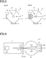
- Fig. 5 is a set of diagrams each illustrating a measurement device used for calculating a diffuse reflectance.
- Fig. 5A is a schematic diagram illustrating a measurement method used for correcting a diffuse reflectance baseline.
- Fig. 5B is a schematic diagram illustrating a measurement method used when measuring a diffuse reflectance of a measurement target.
- Figs. 5A and 5B schematically illustrate a structure of a measurement device in plan view together with standard white plates or measurement targets.
- FIG. 6 is a schematic diagram illustrating an example of a measurement device used for calculating a clarity.
- the screen 10 or 20 is placed between the illumination part 41 and the integrating sphere 43.
- the flux of parallel light LP emitted from the lens 41B has a diameter of 14 mm in the present embodiment.
- the light that has passed through the screen includes straight light LS propagating straight along the optical axis of the parallel light LP that has entered the screen, and narrow-angle scattered light LNS having an angle of ⁇ 2.5° or narrower relative to the optical axis of the parallel light LP.
- the center sensor 42C receives the straight light LS
- the outer peripheral sensor 42R receives the narrow-angle scattered light LNS.
- the intensity of the straight light LS received by the center sensor 42C is defined to be I C
- the intensity of the narrow-angle scattered light LNS received by the outer peripheral sensor 42R is defined to be I R .
- clarity is a parameter for evaluating the state of the screen 10 or 20 by using narrow-angle scattered light. Therefore, clarity can be used for evaluating the degree of sharpness of very small portions of an observation target in an image of the observation target via the screen 10 or 20.
- the contours of the observation target in other words, the sharpness of the observation target, will be blurred more as the value of clarity of the screen 10 or 20 decreases.
- clarity is used for evaluating sharpness in an image of an observation target visually inspected via the screen 10 or 20.
- Haze of the screen 10 or 20 can be calculated based on the intensity measured using the measurement device 40. It should be noted that haze is calculated using a method according to JIS K 7136:2000. When measuring haze using the measurement device 40, the light that has passed through the screen 10 or 20 is received by the light-receiving part disposed in the integrating sphere 43.
- haze refers to a percentage of transmitted light deviated from the incident light by 2.5° or more due to forward scattering, in the light that has passed through the screen 10 or 20.
- parallel light refers to light at an angle of less than ⁇ 2.5° relative to the optical axis of the parallel light LP
- wide-angle scattered light refers to light at an angle of ⁇ 2.5° or more.
- the spectral transmittances ⁇ ( ⁇ ) are obtained through transmission measurements using an integrating sphere with an ultraviolet visible near-infrared spectrometer, in terms of visible light in the wavelength range of 380 nm or more and 780 nm or less.
- the weighting factor D ⁇ ⁇ V( ⁇ ) ⁇ is a value based on JIS A 5759:2016.
- the reflected luminous flux is calculated by measuring spectral reflectances ⁇ ( ⁇ ) of light in the wavelength range of 380 nm or more and 780 nm or less, multiplying each of the measured spectral reflectances ⁇ ( ⁇ ) by a weighting factor D ⁇ ⁇ V ⁇ , and weight-averaging the products.
- the spectral reflectances ⁇ ( ⁇ ) are obtained through reflection measurements using an integrating sphere with an ultraviolet visible near-infrared spectrometer, in terms of visible light in the wavelength range of 380 nm or more and 780 nm or less.
- the weighting factor D ⁇ ⁇ V ⁇ is a value based on JIS A 3106:2019.
- a screen of Example 1 was obtained by sequentially laminating a light control sheet having a polymer network light control layer, a UV cut layer, a transparent reflective layer (SP-MSV50 manufactured by Braintec Inc.), and a transparent substrate. It should be noted that a screen having the first structure described above was obtained as a screen of Example 1. Through measurements using a spectrometer (U-4100, manufactured by Hitachi High-Tech Corporation), the transparent reflective layer was found to have a visible light transmittance of 50% and a visible light reflectance of 25%. Also, through measurements using a spectrometer (the same as above), the transparent reflective layer was found to have a solar radiation reflectance of 24%, a solar radiation transmittance of 40%, and a solar radiation absorptance of 36%.
- a screen of Comparative Example 1 was obtained as in Example 1 except that the transparent reflective layer was replaced by SP-MSV70 (manufactured by Braintec Inc.). Through measurements using a spectrometer (the same as above), the transparent reflective layer was found to have a visible light transmittance of 68% and a visible light reflectance of 12%. Also, through measurements using a spectrometer (the same as above), the transparent reflective layer was found to have a solar radiation reflectance of 13%, a solar radiation transmittance of 56%, and a solar radiation absorptance of 31%.
- Example 2 A screen of Example 2 was obtained as in Example 1 except that the transparent reflective layer was replaced by RE50NIAR (manufactured by 3M Japan Limited). Through measurements using a spectrometer (the same as above), the transparent reflective layer was found to have a visible light transmittance of 51% and a visible light reflectance of 26%. Also, through measurements using a spectrometer (the same as above), the transparent reflective layer was found to have a solar radiation reflectance of 32%, a solar radiation transmittance of 38%, and a solar radiation absorptance of 30%.
- RE50NIAR manufactured by 3M Japan Limited
- Example 3 A screen of Example 3 was obtained as in Example 1 except that the transparent reflective layer was replaced by Nova70 (manufactured by LINTEC Corporation). Through measurements using a spectrometer (the same as above), the transparent reflective layer was found to have a visible light transmittance of 64% and a visible light reflectance of 26%. Also, through measurements using a spectrometer (the same as above), the transparent reflective layer was found to have a solar radiation reflectance of 34%, a solar radiation transmittance of 46%, and a solar radiation absorptance of 20%.
- Nova70 manufactured by LINTEC Corporation
- a screen of Comparative Example 3 was obtained as in Example 1 except that the transparent reflective layer was replaced by Nova35 (manufactured by LINTEC Corporation). Through measurements using a spectrometer (the same as above), the transparent reflective layer was found to have a visible light transmittance of 38% and a visible light reflectance of 46%. Also, through measurements using a spectrometer (the same as above), the transparent reflective layer was found to have a solar radiation reflectance of 52%, a solar radiation transmittance of 24%, and a solar radiation absorptance of 24%.
- a screen of Comparative Example 4 was obtained as in Example 1 except that the screen included no transparent reflective layer.
- Diffuse reflectance, haze and clarity were calculated for each of the screens of Examples 1 to 3 and Comparative Examples 1 to 4 in an opaque state.
- Each diffuse reflectance was measured using UV-3600 (manufactured by Shimadzu Corporation).
- Haze was measured using a hazemeter (NDH7000SP manufactured by Nippon Denshoku Industries Co., Ltd.).
- Clarity was measured using a haze/transparency measurement device (haze-gard i manufactured by BYK-Gardner GmbH). Since the screens of the examples and the comparative examples each had the first structure described above, the parameters were calculated in a state in which no drive voltage was applied to the screens.
- the average diffuse reflectance of Example 1 was 11.8%, that of Comparative Example 1 was 6.8%, and that of Example 2 was 13.0%. Furthermore, the average diffuse reflectance of Example 3 was 14.4%, that of Comparative Example 2 was 22.0%, that of Comparative Example 3 was 31.1%, and that of Comparative Example 4 was 2.9%.
- Example 1 As shown in Table 1, the haze of Example 1 was 98.7%, that of Comparative Example 1 was 98.7%, and that of Example 2 was 98.7%. Furthermore, the haze of Example 3 was 98.0%, that of Comparative Example 2 was 98.8%, that of Comparative Example 3 was 98.8%, and that of Comparative Example 4 was 98.9%.
- Example 1 As shown in Table 1, the clarity of Example 1 was 37.3%, that of Comparative Example 1 was 41.9%, and that of Example 2 was 38.9%. Furthermore, the clarity of Example 3 was 37.6%, that of Comparative Example 2 was 40.3%, that of Comparative Example 3 was 34.2%, and that of Comparative Example 4 was 40.0%.
- Haze and parallel light transmittance were measured for the screens of the examples and the comparative examples in a transparent state. Haze was measured using a hazemeter (NDH7000SP manufactured by Nippon Denshoku Industries Co., Ltd.). Parallel light transmittance was measured using a hazemeter (the same as above).
- Example 1 As shown in Table 2, the haze of Example 1 was 11.1%, that of Comparative Example 1 was 9.5%, and that of Example 2 was 11.9%. Furthermore, the haze of Example 3 was 12.8%, that of Comparative Example 2 was 13.2%, that of Comparative Example 3 was 14.1%, and that of Comparative Example 4 was 5.6%.
- Example 1 the parallel light transmittance of Example 1 was 42.0%, that of Comparative Example 1 was 56.9%, and that of Example 2 was 43.1%. Furthermore, the parallel light transmittance of Example 3 was 55.3%, that of Comparative Example 2 was44.1%, that of Comparative Example 3 was 30.6%, and that of Comparative Example 4 was 81.4%.
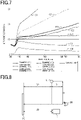
- the difference in height between a light source L and an observer OB was defined to be a height HI.
- the distance between the light source L and the observer OB was defined to be a first distance D1
- the distance between the front surface of the screen 10 and the light source L was defined to be a second distance D2
- the distance between a projector P and the screen 10 was defined to be a third distance D3.
- the projector P was disposed with respect to the screen 10 so that the surface of the light control sheet 10A of the screen 10 facing away from the transparent reflective layer 15 would be the surface to which light was projected.
- the height HI was set to 100 cm
- the first distance D1 was set to 50 cm
- the second and third distances D2 and D3 were both set to 100 cm.
- An image with a luminance of 800 lm was projected from the projector P to the projection surface of each screen 10, for the ten people's visual inspection evaluation of the screen 10 in terms of sharpness of the image, anti-reflective properties for the projected image preventing other image reflections, and anti-glare properties of the screen.
- the screen was evaluated to be good in terms of these parameters.
- the screens of Examples 1 to 3 and Comparative Examples 2 and 3 had high image sharpness. In contrast, the screens of Comparative Examples 1 and 4 had low image sharpness. Furthermore, the screens of Examples 1 to 3 and Comparative Examples 1 and 4 had good anti-reflective properties. In contrast, the screens of Comparative Examples 2 and 3 had poor anti-reflective properties. Furthermore, the screens of Examples 1 to 3 and Comparative Examples 1 and 4 had good anti-glare properties. In contrast, the screens of Comparative Examples 2 and 3 had poor anti-glare properties.
- the screens of Examples 1 to 3 all had satisfactory image sharpness, anti-reflective properties and anti-glare properties.
- the screens of Comparative Examples 1 and 4 had satisfactory anti-reflective properties and anti-glare properties, they were not satisfactory in terms of image sharpness.
- the screens of Comparative Examples 2 and 3 had satisfactory image sharpness, they were not satisfactory in terms of anti-reflective properties and anti-glare properties.
- the screen was satisfactory in terms of both image sharpness and anti-glare properties.
- the screen did not have satisfactory image sharpness
- the screen did not have satisfactory anti-glare properties.
- the difference in height between a light source L and an observer OB was defined to be a height H2.
- the distance between the light source L and the observer OB was defined to be a fourth distance D4
- the distance between the front surface of the screen 10 and the light source L was defined to be a fifth distance D5
- the distance between the screen 10 and an observation target 51 was defined to be a sixth distance D6.
- the height H2 was set to 100 cm
- the fourth distance D4 was set to 50 cm
- the fifth distance D5 was set to 100 cm
- sixth distance D6 was set to 50 cm.
- the screen 10 was disposed so that the projection surface of the screen 10 would face the observer OB.
- the observation target 51 used had a checkerboard pattern in which white and black squares were alternated in both horizontal and vertical directions (Byko-charts manufactured by BYK-Gardner GmbH). In each square, the length of each side was 31 mm.
- the ten people inspected the checkerboard pattern via the screen 10 in a transparent state of each of the examples and the comparative examples.
- transparency of the screen 10 anti-reflective properties for the image of the checkerboard pattern preventing other image reflections, and anti-glare properties were evaluated by visual inspection.
- the screen was evaluated to be good in terms of these parameters. If four or more of the ten people determined the screen to have low transparency and to have only low anti-reflective properties and anti-glare properties, the screen was evaluated to be poor in terms of these parameters.
- the evaluations were as shown in Table 4.
- the screens of Examples 1 to 3 and Comparative Examples 1 and 4 had high transparency. In contrast, the screens of Comparative Examples 2 and 3 had low transparency. The screens of Examples 1 to 3 and Comparative Examples 1 and 4 had good anti-reflective properties. In contrast, the screens of Comparative Examples 2 and 3 had poor anti-reflective properties. The screens of Examples 1 to 3 and Comparative Examples 1 and 4 had good anti-glare properties. In contrast, the screens of Comparative Examples 2 and 3 had poor anti-glare properties.
- the screens of Examples 1 to 3 and Comparative Examples 1 and 4 all had high transparency and were satisfactory in terms of both anti-reflective properties and anti-glare properties.
- neither of the screens of Comparative Examples 2 and 3 had high transparency, and neither of them had satisfactory anti-reflective properties and anti-glare properties.
- the opaque state of the screen can be evaluated by applying a saturation voltage, which is unlikely to change the alignment of the liquid crystal molecules with the increase of the voltage, to the light control layer as a drive voltage of the liquid crystal molecules.
- the UV cut layer 14 may have a maximum transmittance of 1% or more for light having a wavelength of less than 380 nm. In this case as well, if the UV cut layer 14 is capable of absorb or reflect part of light in the wavelength range of UV light, advantageous effect similar to the above item (5) can be achieved.
- the UV cut layer 14 may be laminated on the projection surface 10AF or 20AF of the light control sheet 10A or 20A.
- the screen 10 may include an adhesive layer different from the UV cut layer 14 between the light control sheet 10A or 20A and the transparent reflective layer 15.
- the UV cut layer 14 may be located between the transparent reflective layer 15 and the transparent substrate 16.
- the UV cut layer 14 may also serve as an adhesive layer that adheres the transparent reflective layer 15 to the transparent substrate 16.
- the screen 10 or 20 does not have to necessarily include a UV cut layer 14.
- a UV cut layer 14 in this case as well, as long as the average diffuse reflectance and/or each diffuse reflectance are 10% or more and less than 20% on the screen 10 or 20, advantageous effects similar to the above items (1) and/or (2) can be achieved.
- the transparent reflective layer 15 may have a visible light transmittance of less than 50%. In this case as well, as long as the average diffuse reflectance and/or each diffuse reflectance are 10% or more and less than 20% on the screen 10 or 20 in an opaque state, advantageous effects similar to the above items (1) and/or (2) can be achieved.
- the solar reflectance of the transparent reflective layer 15 may be less than 20% or may be more than 45%. In this case as well, as long as the average diffuse reflectance and/or each diffuse reflectance are 10% or more and less than 20%, advantageous effects similar to the above items (1) and/or (2) can be achieved.
- the screen 10 or 20 When the light control sheet 10A or 20A is in a transparent state, the screen 10 or 20 does not have to satisfy either of the haze being 12.8% or less and the parallel light transmittance being 42% or more. In this case as well, as long as the average diffuse reflectance and/or each diffuse reflectance of the screen 10 or 20 are 10% or more and less than 20%, advantageous effects similar to the above items (1) and/or (2) can be achieved.
- the screen 10 or 20 does not have to satisfy either of the haze being 98% or more and the clarity being 42% or less.
- the average diffuse reflectance and/or each diffuse reflectance are 10% or more and less than 20%, advantageous effects similar to the above items (1) and/or (2) can be achieved.
- the screen 10 or 20 can also be used as a partition.
- the screen 10 or 20 can be used in place of, for example, a curtain, blind, or shoji (Japanese-style paper screen).
- the state of the screen 10 or 20 in use can be changed as follows. For example, the spaces defined by the screen 10 or 20 in a transparent state can be visually inspected from each other through the screen 10 or 20. Also, the spaces defined by the screen 10 or 20 in an opaque state can each be hidden from the other.
- the screen 10 or 20 does not necessarily have to have flat surfaces but may have curved surfaces. If the screen 10 or 20 has curved surfaces as well, they can minimize glare as long as the average diffuse reflectance and each diffuse reflectance are in the range as described in the present embodiment. Therefore, for example, if a curved screen having an arc shape is placed surrounding an observer with the projection surface facing the observer, the observer can be imparted with high immersive feeling by the image projected to the curved screen.
Landscapes
- Physics & Mathematics (AREA)
- Nonlinear Science (AREA)
- General Physics & Mathematics (AREA)
- Optics & Photonics (AREA)
- Chemical & Material Sciences (AREA)
- Crystallography & Structural Chemistry (AREA)
- Mathematical Physics (AREA)
- Dispersion Chemistry (AREA)
- Overhead Projectors And Projection Screens (AREA)
- Optical Elements Other Than Lenses (AREA)
- Projection Apparatus (AREA)
- Liquid Crystal (AREA)
Applications Claiming Priority (2)
| Application Number | Priority Date | Filing Date | Title |
|---|---|---|---|
| JP2019121810A JP6669300B1 (ja) | 2019-06-28 | 2019-06-28 | スクリーン |
| PCT/JP2020/025262 WO2020262622A1 (fr) | 2019-06-28 | 2020-06-26 | Écran |
Publications (2)
| Publication Number | Publication Date |
|---|---|
| EP3992711A1 true EP3992711A1 (fr) | 2022-05-04 |
| EP3992711A4 EP3992711A4 (fr) | 2022-08-24 |
Family
ID=70000696
Family Applications (1)
| Application Number | Title | Priority Date | Filing Date |
|---|---|---|---|
| EP20831595.2A Pending EP3992711A4 (fr) | 2019-06-28 | 2020-06-26 | Écran |
Country Status (5)
| Country | Link |
|---|---|
| US (1) | US11609488B2 (fr) |
| EP (1) | EP3992711A4 (fr) |
| JP (1) | JP6669300B1 (fr) |
| CN (1) | CN113785241A (fr) |
| WO (1) | WO2020262622A1 (fr) |
Families Citing this family (1)
| Publication number | Priority date | Publication date | Assignee | Title |
|---|---|---|---|---|
| JP7592990B2 (ja) * | 2020-07-01 | 2024-12-03 | Toppanホールディングス株式会社 | 遊具用投影システム |
Family Cites Families (25)
| Publication number | Priority date | Publication date | Assignee | Title |
|---|---|---|---|---|
| US7453635B2 (en) * | 2004-08-10 | 2008-11-18 | Fusion Optix Inc. | Imaging material with improved contrast |
| JP2006221070A (ja) * | 2005-02-14 | 2006-08-24 | Sony Corp | 反射型スクリーン |
| US7973749B2 (en) * | 2006-01-31 | 2011-07-05 | Nec Lcd Technologies, Ltd. | Display device, terminal device, and display panel |
| KR101441584B1 (ko) * | 2008-01-02 | 2014-09-23 | 삼성전자 주식회사 | 투과형 영상표시장치 및 그 방법 |
| US8913215B2 (en) * | 2008-03-24 | 2014-12-16 | Kent State University | Bistable switchable liquid crystal window |
| JP5548485B2 (ja) * | 2009-03-27 | 2014-07-16 | 株式会社きもと | 透過型スクリーンおよびこれを用いたリアプロジェクションモニタ |
| JP2011059589A (ja) * | 2009-09-14 | 2011-03-24 | Sony Ericsson Mobilecommunications Japan Inc | 表示装置、携帯情報端末、携帯情報端末の表示制御方法及び表示制御プログラム、 |
| JP2011175110A (ja) * | 2010-02-24 | 2011-09-08 | Seiko Epson Corp | 画像形成装置および背面投影型表示装置 |
| JP2012220540A (ja) * | 2011-04-04 | 2012-11-12 | Asahi Glass Co Ltd | 透過型スクリーンおよび映像表示装置 |
| JP2014080606A (ja) * | 2012-09-27 | 2014-05-08 | Mitsubishi Chemicals Corp | 液晶組成物、液晶素子、該液晶素子を用いたスクリーン及びディスプレイ、並びに液晶組成物の製造方法 |
| JP6429102B2 (ja) * | 2014-04-22 | 2018-11-28 | 大日本印刷株式会社 | 画像表示装置 |
| JPWO2016068087A1 (ja) * | 2014-10-27 | 2017-08-31 | 旭硝子株式会社 | 透過型透明スクリーン、映像表示システムおよび映像表示方法 |
| JP6489816B2 (ja) * | 2014-12-09 | 2019-03-27 | アキレス株式会社 | 反射型プロジェクタースクリーン |
| JP6584819B2 (ja) * | 2015-03-27 | 2019-10-02 | マクセルホールディングス株式会社 | 透明スクリーン機能を備えた透明遮熱部材 |
| US9678256B2 (en) * | 2015-03-27 | 2017-06-13 | Hitachi Maxell, Ltd. | Transparent heat-shielding member |
| CN107533280B (zh) * | 2015-04-22 | 2021-02-26 | 大日本印刷株式会社 | 屏幕、显示装置、屏幕的使用方法、粒子、粒子层、粒子片和光控制片 |
| JP2017001649A (ja) * | 2015-06-16 | 2017-01-05 | 旭硝子株式会社 | 可動ドア装置 |
| CN108139661A (zh) * | 2015-10-08 | 2018-06-08 | 大日本印刷株式会社 | 颗粒、光学片、屏幕、显示装置、颗粒检查装置和颗粒制造装置、以及颗粒检查方法、颗粒制造方法、屏幕检查方法和屏幕制造方法 |
| JP2017090617A (ja) * | 2015-11-09 | 2017-05-25 | 旭硝子株式会社 | 調光機能付きスクリーンガラスおよび映像表示システム |
| JP2017090616A (ja) * | 2015-11-09 | 2017-05-25 | 旭硝子株式会社 | スクリーン機能付きブラインドガラスおよび映像表示システム |
| JP6763402B2 (ja) * | 2015-12-25 | 2020-09-30 | Agc株式会社 | 反射型透明スクリーン |
| US10684543B2 (en) * | 2016-04-12 | 2020-06-16 | Corning Incorporated | Smart window projection screen |
| JP6888431B2 (ja) * | 2016-06-10 | 2021-06-16 | 凸版印刷株式会社 | プロジェクションスクリーン、および、画像表示システム |
| WO2019039163A1 (fr) * | 2017-08-25 | 2019-02-28 | セントラル硝子株式会社 | Écran transparent, et système d'affichage |
| JP2019045612A (ja) * | 2017-08-31 | 2019-03-22 | 凸版印刷株式会社 | 調光フィルム、及びそれを用いた調光装置 |
-
2019
- 2019-06-28 JP JP2019121810A patent/JP6669300B1/ja active Active
-
2020
- 2020-06-26 CN CN202080032677.7A patent/CN113785241A/zh active Pending
- 2020-06-26 WO PCT/JP2020/025262 patent/WO2020262622A1/fr not_active Ceased
- 2020-06-26 EP EP20831595.2A patent/EP3992711A4/fr active Pending
-
2021
- 2021-12-23 US US17/560,742 patent/US11609488B2/en active Active
Also Published As
| Publication number | Publication date |
|---|---|
| US20220113617A1 (en) | 2022-04-14 |
| WO2020262622A1 (fr) | 2020-12-30 |
| CN113785241A (zh) | 2021-12-10 |
| EP3992711A4 (fr) | 2022-08-24 |
| JP6669300B1 (ja) | 2020-03-18 |
| US11609488B2 (en) | 2023-03-21 |
| JP2021009189A (ja) | 2021-01-28 |
Similar Documents
| Publication | Publication Date | Title |
|---|---|---|
| EP3796073B1 (fr) | Dispositif de gradation, procédé de gestion de dispositif de gradation et procédé de production de dispositif de gradation | |
| CN104919342B (zh) | 增强色觉缺陷个体的辨色能力的滤光片 | |
| EP2715440B1 (fr) | Surface antireflet conçue pour réduire le scintillement d'un affichage | |
| US12049062B2 (en) | Glass laminate including reflective film | |
| EP3992702B1 (fr) | Feuille de modulation de lumière et dispositif de modulation de lumière | |
| US12108195B2 (en) | Reflective screen and image display device | |
| CN108369368B (zh) | 反射型透明屏幕 | |
| US20150301366A1 (en) | Glazing unit comprising a variable light scattering system and a pair of absorbing elements | |
| JP7736135B2 (ja) | 調光シート、および、調光シートの管理方法 | |
| US11609488B2 (en) | Screen | |
| US20230347625A1 (en) | Vehicle compound glazing unit with projection area | |
| CN101542326B (zh) | 显示器件的滤光片 | |
| EP4053619B1 (fr) | Dispositif de contôle de lumière et procédé de commande d'une feuille de contôle de lumière | |
| EP4190611A1 (fr) | Structure optique et affichage tête haute | |
| KR100727507B1 (ko) | 반사식 표시 장치 | |
| JPS5964802A (ja) | 円偏光盤 | |
| EP4644978A1 (fr) | Écran de projection de type à réflexion |
Legal Events
| Date | Code | Title | Description |
|---|---|---|---|
| STAA | Information on the status of an ep patent application or granted ep patent |
Free format text: STATUS: THE INTERNATIONAL PUBLICATION HAS BEEN MADE |
|
| PUAI | Public reference made under article 153(3) epc to a published international application that has entered the european phase |
Free format text: ORIGINAL CODE: 0009012 |
|
| STAA | Information on the status of an ep patent application or granted ep patent |
Free format text: STATUS: REQUEST FOR EXAMINATION WAS MADE |
|
| 17P | Request for examination filed |
Effective date: 20211018 |
|
| AK | Designated contracting states |
Kind code of ref document: A1 Designated state(s): AL AT BE BG CH CY CZ DE DK EE ES FI FR GB GR HR HU IE IS IT LI LT LU LV MC MK MT NL NO PL PT RO RS SE SI SK SM TR |
|
| A4 | Supplementary search report drawn up and despatched |
Effective date: 20220722 |
|
| RIC1 | Information provided on ipc code assigned before grant |
Ipc: G02B 5/02 20060101ALI20220718BHEP Ipc: G02F 1/13 20060101ALI20220718BHEP Ipc: G02B 5/08 20060101ALI20220718BHEP Ipc: G03B 21/62 20140101AFI20220718BHEP |
|
| DAV | Request for validation of the european patent (deleted) | ||
| DAX | Request for extension of the european patent (deleted) | ||
| STAA | Information on the status of an ep patent application or granted ep patent |
Free format text: STATUS: EXAMINATION IS IN PROGRESS |
|
| 17Q | First examination report despatched |
Effective date: 20240912 |
|
| STAA | Information on the status of an ep patent application or granted ep patent |
Free format text: STATUS: THE APPLICATION IS DEEMED TO BE WITHDRAWN |