EP3992727B1 - Mechanisches uhrwerk mit erfassung der gangreserve - Google Patents
Mechanisches uhrwerk mit erfassung der gangreserve Download PDFInfo
- Publication number
- EP3992727B1 EP3992727B1 EP20204874.0A EP20204874A EP3992727B1 EP 3992727 B1 EP3992727 B1 EP 3992727B1 EP 20204874 A EP20204874 A EP 20204874A EP 3992727 B1 EP3992727 B1 EP 3992727B1
- Authority
- EP
- European Patent Office
- Prior art keywords
- movement
- lever
- wheel
- barrel system
- power reserve
- Prior art date
- Legal status (The legal status is an assumption and is not a legal conclusion. Google has not performed a legal analysis and makes no representation as to the accuracy of the status listed.)
- Active
Links
Images




Classifications
-
- G—PHYSICS
- G04—HOROLOGY
- G04B—MECHANICALLY-DRIVEN CLOCKS OR WATCHES; MECHANICAL PARTS OF CLOCKS OR WATCHES IN GENERAL; TIME PIECES USING THE POSITION OF THE SUN, MOON OR STARS
- G04B9/00—Supervision of the state of winding, e.g. indicating the amount of winding
- G04B9/005—Supervision of the state of winding, e.g. indicating the amount of winding by optical indication of the amount of winding
-
- G—PHYSICS
- G04—HOROLOGY
- G04B—MECHANICALLY-DRIVEN CLOCKS OR WATCHES; MECHANICAL PARTS OF CLOCKS OR WATCHES IN GENERAL; TIME PIECES USING THE POSITION OF THE SUN, MOON OR STARS
- G04B1/00—Driving mechanisms
- G04B1/10—Driving mechanisms with mainspring
- G04B1/12—Driving mechanisms with mainspring with several mainsprings
-
- G—PHYSICS
- G04—HOROLOGY
- G04B—MECHANICALLY-DRIVEN CLOCKS OR WATCHES; MECHANICAL PARTS OF CLOCKS OR WATCHES IN GENERAL; TIME PIECES USING THE POSITION OF THE SUN, MOON OR STARS
- G04B1/00—Driving mechanisms
- G04B1/10—Driving mechanisms with mainspring
- G04B1/16—Barrels; Arbors; Barrel axles
-
- G—PHYSICS
- G04—HOROLOGY
- G04B—MECHANICALLY-DRIVEN CLOCKS OR WATCHES; MECHANICAL PARTS OF CLOCKS OR WATCHES IN GENERAL; TIME PIECES USING THE POSITION OF THE SUN, MOON OR STARS
- G04B9/00—Supervision of the state of winding, e.g. indicating the amount of winding
-
- G—PHYSICS
- G04—HOROLOGY
- G04B—MECHANICALLY-DRIVEN CLOCKS OR WATCHES; MECHANICAL PARTS OF CLOCKS OR WATCHES IN GENERAL; TIME PIECES USING THE POSITION OF THE SUN, MOON OR STARS
- G04B9/00—Supervision of the state of winding, e.g. indicating the amount of winding
- G04B9/02—Devices controlled by such state, e.g. device affording protection means against overwinding
Definitions
- the present invention relates to a mechanical clock movement provided with power reserve detection means.
- a power reserve of a mechanical watch movement of a mechanical watch makes it possible to display to a person wearing the watch the operating time before the watch movement stops. It has been observed that the power reserve from one watch to another can vary significantly depending mainly on the manufacturing tolerances of the watch, wear, lubrication, roughness.
- a mechanical clockwork movement generally comprises a barrel system driving at least one load output wheel and one discharge output wheel connected respectively to a load wheel and a discharge wheel of a differential.
- a set of wheels connected to an intermediate wheel of the differential controls a power reserve display, but no element of the movement is provided for a movement blocking operation when the power reserve is at zero.
- the patent EP 0 568 499 B1 describes a power reserve indicating device for a mechanical watch.
- the indicating device comprises at least one star wheel with an indicating member, which is rotated when the barrel is charged or discharged.
- the indicating member makes it possible to display the power reserve of the watch. However, nothing is provided to ensure that the movement is blocked when the power reserve approaches zero.
- the patent CH 698 752 B1 describes a timepiece, which includes a power reserve indicator mechanism. It includes two barrels facing each other and connected by a common shaft, which controls the power reserve display mechanism. However, nothing is provided to ensure that the movement is blocked when the power reserve approaches zero.
- the patent application CH 710 320 A2 describes a timepiece, which comprises a source of mechanical energy, such as a barrel and a control member in connection with a control device in the watch case.
- the control device comprises a power reserve wheel pivotally mounted on the frame and connected to the barrel by a differential so that the angular position of the power reserve wheel is a function of the charge level of the barrel.
- a control cam is pivotally mounted on the same axis as the power reserve wheel.
- the control cam has a slot extending in an arc of a circle in which is housed a pin secured to the power reserve wheel.
- a spiral spring is mounted between the power reserve wheel and the cam.
- a stop device which comprises a stop lever, to block the movement when the power reserve is close to zero.
- a stop lever to block the movement when the power reserve indicator is at zero.
- the main aim of the invention is therefore to overcome the drawbacks of the state of the art by proposing a mechanical watch movement equipped with power reserve detection means and capable of directly blocking the operation of the movement, when the power reserve is close to or equal to zero, using a minimum of components to obtain a compact system.
- the present invention relates to a mechanical watch movement provided with power reserve detection means, which comprises the characteristics of independent claim 1.
- An advantage of the mechanical watch movement with the power reserve detection means is that an increase in the accuracy of the power reserve indication is achieved.
- the power reserve detection means are implemented in such a way that the power reserve indication at zero corresponds to the actual stopping of the mechanical watch movement.
- a control element which may be a wheel or a plate, is preferably directly connected to a wheel of a drive wheel arrangement at the output of the differential to be driven in rotation or in a rectilinear direction.
- a control element is preferably directly connected to a wheel of a drive wheel arrangement at the output of the differential to be driven in rotation or in a rectilinear direction.
- the power reserve detection means preferably comprise a control wheel and a rotatably mounted lever. around a lever axis and cooperating with the control wheel so as to determine on the one hand that the barrel is fully charged, and on the other hand that the barrel is substantially completely discharged for the power reserve indication at zero.
- the control wheel comprises an opening in the form of an arc of a circle of a determined angle and centered on the axis of the wheel
- the control lever comprises a contact element, such as a rod or a pin or a blade inserted into the opening of the control wheel.
- the axis of the wheel is arranged parallel to the central axis of the barrel system.
- the opening of the control wheel comprises a first end for determining a 100% power reserve of the barrel and a second end for determining a 0% power reserve of the barrel system.
- the first and second ends have circular portions.
- the circular portions at the ends define half of a circle of radius corresponding to half the width of the opening.
- the power reserve is at 100%, i.e. the barrel system is fully charged, when the rod or pin, or when a complementary rod or complementary pin which may be the central axis of the barrel system between the rod or pin of the lever and the first end, comes into contact with the first end.
- the power reserve is at zero when the rod or pin or the blade of the lever comes into contact with the second end.
- the lever pivots around its axis of rotation in such a way as to allow a locking part of the lever to come and block any element of the movement causing the complete and instantaneous stopping of the movement.
- the lever comprises a locking piece at one end of the lever coming into frictional contact with a peripheral edge of the barrel system cage to block the watch movement.
- the locking piece is located at an end opposite that of the contact element, which is the inserted rod or pin in the wheel opening.
- the axis of rotation of the lever is located close to the locking piece and arranged in such a way that in the locking position, rotation of the lever brings the locking piece against the peripheral edge of the barrel system.
- the lever comprises a locking part in the form of a tooth at one end of the lever for being inserted between two teeth of a toothed wheel on the periphery of the barrel system.
- the locking part is located at an end opposite that of the rod or pin inserted into the opening of the wheel.
- the axis of rotation of the lever is located near the rod where the pin of the lever is arranged in such a way that in the locking position, the rotation of the lever brings the tooth into the peripheral teeth of the barrel system.
- the lever comprises a locking piece at a remote end of the lever for engaging a rim of a balance spring as a mechanical oscillator.
- the axis of rotation of the lever is at an end opposite the locking piece, while the rod or pin inserted into the opening of the wheel is in an intermediate position, but close to the axis of rotation of the lever.
- the power reserve detection means may comprise a control element in the form of a plate, which comprises a rectilinear opening with a first end and a second end, and a control lever rotatably mounted with a rod or a pin at one end of the lever, and inserted into the rectilinear opening.
- the control element can be moved rectilinearly between guide portions by means of a toothed wheel at the outlet of the barrel meshing with a toothed rectilinear portion on one side of the control element.
- FIG. figure 1b represent three-dimensional top views of some components of the mechanical clockwork movement 1 with the power reserve detection means 10, as well as a top plan view in the position of the power reserve means illustrated in FIG. figure 1b of a first embodiment.
- the mechanical clockwork movement 1 for a watch is in the normal operating position in figure 1a and in the movement blocking position in figure 1b with a power reserve equal to zero, as well as in figure 1c .
- the mechanical watch movement 1 comprises at least the barrel system 2, which is arranged for example on a face of a watch plate of the movement (not shown) or another support plate.
- This barrel system 2 can be a single barrel or two barrels or more than two barrels well known and having a charge output and a discharge output, as well as a differential for driving a time base gear train.
- a differential barrel system 2 may be used with a toothed wheel 24 peripheral to the cage of the barrel system 2 to drive at least one large medium wheel of the finishing gear and/or a drive gear starting from the axis or shaft 16 of the barrel system 2.
- At least one drive wheel is provided connected to the central axis or shaft 16 of the barrel system 2.
- a drive wheel 7' is fixed either on the cage of the barrel system 2 to rotate with the cage, or linked to the central axis or shaft 16 of the barrel system 2.
- the cage of the barrel system 2 rotates in the same direction as the central axis or shaft 16 of the barrel system 2.
- the first drive wheel arrangement 7, 7' and also a second drive wheel arrangement 6, 6', 6" are provided as a differential barrel system 2 is used.
- the first drive wheel arrangement 7, 7' is connected to a discharge input of the differential, while the second drive wheel arrangement 6, 6', 6" is connected to a load input of the differential.
- the first drive wheel arrangement 7, 7' comprises a first base wheel 7 fixed to the cage of the barrel system 2
- the second drive wheel arrangement 6, 6', 6" comprises a first base wheel 6 connected directly to the central axle or shaft 16 of the barrel system 2.
- the means 10 for detecting the power reserve of the mechanical watch movement 1 comprise a control element 3, which may be a control wheel as presented in this first embodiment, or also a control plate movable in a rectilinear direction.
- the control wheel 3 is arranged opposite the cage of the barrel system 2, and may be arranged to rotate about an axis of rotation 23 parallel to the central axis 16 of the barrel system 2.
- a complementary member 8 in the form of a complementary wheel 8 in this case drives the control wheel 3 in a direction of loading or unloading of the barrel system 2 in particular at the output of a differential.
- the control wheel 3 comprises an opening 13 as a control portion, said opening 13 having a first end 21 for defining a full charge of the barrel system 2 and a second end 22 for defining a full discharge of the barrel system 2 for indicating the power reserve at zero.
- the opening 13 is in the form of an arc of a circle of a determined angle and centered on the axis 23 of the control wheel 3 while being parallel to the central axis or shaft 16 of the barrel system 2.
- the first end 21 of the opening 13 and the second end 22 of the opening 13 have the shape of circular portions. These circular portions at the two ends define half of a circle of radius corresponding to half the width of the opening 13.
- the means 10 for detecting the power reserve of the mechanical watch movement 1 also comprise a lever 4, which can preferably be rotatably mounted about a lever axis 14 parallel to the axis of rotation 23 of the control wheel 3 and/or parallel to the central axis 16 of the barrel system 2.
- the lever 4 comprises a contact element 5 arranged in the opening 13 of the control element 3, which is the control wheel 3 in this first embodiment, to come into contact with the second end 22 of the opening 13 when the power reserve is indicated at zero.
- the lever 4 is pushed in rotation about its lever axis 14 by the second end 22 so that a blocking part 15 of the lever 4 comes into contact with the cage of the barrel system 2 and is preferably in contact with an edge 12 of the cage of the barrel system 2.
- the axis of rotation 14 of the lever is arranged close to the blocking part 15 which can be a wedge or a stud fixed under a surface of the lever 4 or coming from the same material directly with the lever 4 in general.
- the wedge or stud normally does not include any rib on its periphery to be only in abutment against the edge 12 of the barrel system 2 in order to block the movement by friction.
- the lever 4 may be movable in rotation or in a rectilinear manner.
- the lever 4 may comprise a contact element 5, which is arranged opposite a control portion 13 of the control element 3 or in a control portion 13 of the control element 3.
- the control element 3 may be a wheel with a control portion in the form of a cam with a locking member on the cam defining a power reserve at zero.
- the contact element 5 in the form of a feeler or a wedge comes in direct contact with the blocking organ when the power reserve is at zero to block the movement by the blocking part 15 of the lever 4.
- the first drive wheel arrangement further comprises a second wheel 7' mounted coaxially on the axis of the complementary member 8 in the form of a wheel, and a first wheel 7 for rotating the second wheel 7', said first wheel 7 being fixed on the cage of the barrel system 2 at the central axis 16 of the barrel system 2.
- the first wheel 7 is traversed by the central axis or shaft 16 of the barrel system 2.
- the two wheels 7, 7' and the complementary wheel 8 are toothed wheels to allow at least the first wheel 7 to drive said second wheel 7' by gearing.
- the contact between the second wheel 7' and the complementary wheel 8, as well as the contact between the third wheel 6" and the complementary wheel 8 passes through balls. There is a differential effect between the second wheel 7' and the third wheel 6" by sandwich contact of said balls.
- the complementary toothed wheel 8 meshes with the control wheel 3 which includes peripheral teeth.
- the second arrangement of drive wheels 6, 6', 6" for charging the barrel system 2 comprises a first wheel 6 directly connected to the central axis or shaft 16 of the barrel system 2.
- This first toothed wheel 6 meshes with a second toothed wheel 6' arranged in the same plane as the first wheel 6 and rotating about an axis of rotation 18.
- This second toothed wheel 6' is also provided to mesh with a third wheel 6" arranged between the complementary wheel 8 and the second wheel 7' of the first arrangement of drive wheels and in a coaxial manner.
- the complementary wheel 8 will rotate in one direction or another.
- the wheel arrangements described above make it possible to connect the charging and discharging of the barrel system 2, as as an energy reservoir, to the display of the power reserve indication.
- the second arrangement of drive wheels 6, 6', 6" transmits with a good transmission ratio the charge of the barrel system 2 (winding), while the first arrangement of drive wheels 7, 7' transmits with the good transmission ratio the discharge of the barrel system 2 (normal discharge during operation).
- the differential is provided to average these two pieces of information and transmit them to the display.
- first end 21 of the opening 13 corresponding to the complete charge of the barrel system 2 comes into contact either with the contact element 5 of the lever 4 or in this case with a part linked to the central axis 16 of the barrel system 2.
- FIGS. 2a, 2b And 2c represent two three-dimensional views from above and a top view of the position shown in figure 2b of a second simplified embodiment of the mechanical clockwork movement provided with the power reserve detection means according to the invention.
- the essential difference is at the level of the blocking part 15 of the lever 4 which is a tooth capable of coming into the teeth of a peripheral toothed wheel 24 of the cage of the barrel system 2 as the power reserve is at zero to block the movement.
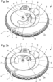
- the third form of execution represented in Figures 3a, 3b And 3c differ from the other two forms of execution, because it is not a blocking at the level of the cage of the barrel system which takes place when the power reserve is at zero, but a blocking of a 30 serge of a mechanical oscillator. However, the blocking of the movement takes place from the same way as the embodiments described above by the blocking piece 15 in contact with the serge 30. The entire description of these elements will therefore not be repeated.
Landscapes
- Physics & Mathematics (AREA)
- General Physics & Mathematics (AREA)
- Electromechanical Clocks (AREA)
- Measurement Of Unknown Time Intervals (AREA)
- Retarders (AREA)
- Transmission Devices (AREA)
- Motorcycle And Bicycle Frame (AREA)
Claims (11)
- Mechanisches Uhrwerk (1), das mit Mitteln (10) zum Erfassen der Gangreserve einer Uhr versehen ist, wobei das Uhrwerk mindestens ein Federhaussystem (2) mit mindestens einer ersten Antriebsradanordnung (7, 7'), die mit dem Ausgang der zentralen Achse (16) des Federhaussystemes (2) verbunden ist, und einer zweiten Antriebsradanordnung (6, 6', 6"), die mit einem Werkgestell des Federhaussystemes (2) auf der Achse (16) verbunden ist, umfasst,das Mittel (10) zur Erfassung der Energiereserve ein Steuerelement (3) umfasst, das gegenüber dem Werkgestell des Federhaussystemes (2) angeordnet und dazu bestimmt ist, sich um eine zur Mittelachse (16) des Federhaussystemes (2) parallele Drehachse (23) zu drehen oder sich in einer geradlinigen Richtung zu bewegen, wobei es durch ein komplementäres Organ (8) am Auslass eines Differenzials angetrieben wird, und einen Hebel (4), der ein Kontaktelement (5) umfasst, das gegenüber einem Steuerteil (13) des Steuerelements (3) oder in einem Steuerteil (13) des Steuerelements (3) angeordnet ist, und um den Hebel (4) so zu bewegen, dass ein Blockierteil (15) des Hebels (4) ein Element des Räderwerks berührt, unabhängig davon, ob es direkt oder indirekt mit dem Räderwerk oder dem Oszillator des Uhrwerks verbunden ist, um das mechanische Uhrwerk direkt anzuhalten, wenn die Gangreserveanzeige bei Null ist,dadurch gekennzeichnet, dass das Steuerelement (3) eine Öffnung (13) als einen Steuerabschnitt umfasst, wobei die Öffnung (13) ein erstes Ende (21) aufweist, um eine vollständige Ladung des Trommelsystems zu definieren, und ein zweites Ende (22), um eine vollständige Entladung des Federhaussystemes (2) zu definieren, um die Gangreserve bei Null anzuzeigen, und den Hebel (4), der um eine Hebelachse (14) parallel zur Drehachse (23) oder parallel zur Mittelachse (16) des Trommelsystems (2) drehbar angebracht ist, wobei der Hebel (4) das Kontaktelement (5) umfasst, das in der Öffnung (13) des Steuerelements (3) angeordnet ist, um das zweite Ende (22) der Öffnung (13) zu berühren, wenn die Gangreserve bei Null ist.
- Mechanisches Uhrwerk (1) nach Anspruch 1, dadurch gekennzeichnet, dass das Steuerelement (3) ein Steuerrad (3) ist, und dass die Öffnung (13) eine kreisbogenförmige Öffnung mit einem bestimmten Winkel und zentriert auf der Achse (23) des Steuerrades (3) ist.
- Mechanisches Uhrwerk (1) nach Anspruch 2, dadurch gekennzeichnet, dass das erste Ende (21) der Öffnung (13) und das zweite Ende (22) der Öffnung (13) die Form von kreisförmigen Abschnitten haben.
- Mechanisches Uhrwerk (1) nach Anspruch 3, dadurch gekennzeichnet, dass die kreisförmigen Abschnitte an den Enden einen Halbkreis mit einem Radius definieren, der der halben Breite der Öffnung (13) entspricht.
- Mechanisches Uhrwerk (1) nach Anspruch 2, dadurch gekennzeichnet, dass das Kontaktelement (5) des Hebels (4) ein Stift oder eine Stange oder eine Klinge ist, die durch die Öffnung (13) hindurch angeordnet ist.
- Mechanisches Uhrwerk (1) nach Anspruch 1, dadurch gekennzeichnet, dass das Blockierteil (15) dazu bestimmt ist, einen Rand (12) des Werkgestells des Federhaussystemes (2) zu berühren, wenn die Gangreserve bei Null ist, um das Uhrwerk zu blockieren.
- Mechanisches Uhrwerk (1) nach Anspruch 1, dadurch gekennzeichnet, dass das Blockierteil (15) an einem Ende, das einer Drehachse (14) des Hebels (4) gegenüberliegt, einen Zahn aufweist, der in der Zahnung eines Umfangszahnrads (24) des Werkgestells des Federhaussystemes (2) untergebracht werden soll, um das Uhrwerk zu blockieren, wenn die Gangreserve bei Null ist.
- Mechanisches Uhrwerk (1) nach Anspruch 1, dadurch gekennzeichnet, dass das Blockierteil (15) eine Stange oder einen Zapfen (14) des Hebels (4) umfasst, um einen Kranz (31) eines mechanischen Oszillators (30) zu berühren, um das Uhrwerk zu blockieren, wenn die Gangreserve bei Null ist.
- Mechanisches Uhrwerk (1) nach einem der Ansprüche 1 bis 2, dadurch gekennzeichnet, dass das Uhrwerk die erste Antriebsradanordnung (7, 7'), die mit einem Differenzialentlastungsauslass des Federhaussystemes (2) verbunden ist, und eine zweite Antriebsradanordnung (6, 6', 6"), die mit einem Differenziallastauslass des Federhaussystemes (2) verbunden ist, umfasst, dass ein erstes Antriebsrad (7) der ersten Antriebsradanordnung (7, 7') fest mit dem Werkgestell des Federhaussystemes (2) verbunden ist, während ein erstes Antriebsrad (6) der zweiten Antriebsradanordnung (6, 6', 6") direkt mit der Mittelachse (16) des Federhaussystemes (2) verbunden ist, und dass der Differenzialauslass das Steuerelement (3), das ein Steuerrad (3) ist, in Drehung versetzt.
- Mechanisches Uhrwerk (1) nach Anspruch 9, dadurch gekennzeichnet, dass das komplementäre Element (8) am Differenzialauslass ein komplementäres Zahnrad (8) ist, das mit dem Steuerzahnrad (3) kämmt.
- Mechanisches Uhrwerk (1) nach Anspruch 1, dadurch gekennzeichnet, dass der Hebel (4) drehbar oder geradlinig bewegbar ist, dass der Hebel (4) ein Kontaktelement (5) aufweist, das gegenüber einem Steuerabschnitt (13) des Steuerelements (3) oder in einem Steuerabschnitt (13) des Steuerelements (3) angeordnet ist, das ein Rad mit einem Steuerabschnitt (13) in Form einer Kurvenscheibe ist, wobei ein Blockierorgan auf der Kurvenscheibe eine Gangreserve bei Null festlegt, und dass das Kontaktelement (5) in Form eines Tasters oder einer Kante das Blockierorgan direkt berührt, wenn die Gangreserve bei Null ist, um die Bewegung durch das Blockierteil (15) des Hebels (4) zu blockieren.
Priority Applications (5)
| Application Number | Priority Date | Filing Date | Title |
|---|---|---|---|
| EP20204874.0A EP3992727B1 (de) | 2020-10-30 | 2020-10-30 | Mechanisches uhrwerk mit erfassung der gangreserve |
| US17/381,425 US11971687B2 (en) | 2020-10-30 | 2021-07-21 | Mechanical horological movement with power reserve detection |
| JP2021128718A JP7238045B2 (ja) | 2020-10-30 | 2021-08-05 | パワーリザーブ検出器を有する機械式測時器ムーブメント |
| KR1020210105469A KR102676395B1 (ko) | 2020-10-30 | 2021-08-10 | 예비 전력 검출부를 가진 기계적 시측 무브먼트 |
| CN202111272979.4A CN114442463B (zh) | 2020-10-30 | 2021-10-29 | 带有动力储备检测的机械钟表机芯 |
Applications Claiming Priority (1)
| Application Number | Priority Date | Filing Date | Title |
|---|---|---|---|
| EP20204874.0A EP3992727B1 (de) | 2020-10-30 | 2020-10-30 | Mechanisches uhrwerk mit erfassung der gangreserve |
Publications (2)
| Publication Number | Publication Date |
|---|---|
| EP3992727A1 EP3992727A1 (de) | 2022-05-04 |
| EP3992727B1 true EP3992727B1 (de) | 2024-09-04 |
Family
ID=73040001
Family Applications (1)
| Application Number | Title | Priority Date | Filing Date |
|---|---|---|---|
| EP20204874.0A Active EP3992727B1 (de) | 2020-10-30 | 2020-10-30 | Mechanisches uhrwerk mit erfassung der gangreserve |
Country Status (5)
| Country | Link |
|---|---|
| US (1) | US11971687B2 (de) |
| EP (1) | EP3992727B1 (de) |
| JP (1) | JP7238045B2 (de) |
| KR (1) | KR102676395B1 (de) |
| CN (1) | CN114442463B (de) |
Citations (1)
| Publication number | Priority date | Publication date | Assignee | Title |
|---|---|---|---|---|
| EP3306415B1 (de) * | 2016-10-04 | 2020-05-20 | ETA SA Manufacture Horlogère Suisse | Mechanisches uhrwerk mit erfassung der gangreserve |
Family Cites Families (10)
| Publication number | Priority date | Publication date | Assignee | Title |
|---|---|---|---|---|
| EP0568499B1 (de) | 1992-04-29 | 1997-05-21 | Exidel Sa | Vorrichtung zur Anzeige der Gangreserve einer Uhr |
| CH698752B1 (fr) | 2004-11-10 | 2009-10-15 | Frank Mueller Watchland S A | Pièce d'horlogerie avec mécanisme d'indication de la réserve de marche. |
| EP1970778B1 (de) | 2007-03-13 | 2009-09-16 | Montres Breguet S.A. | Uhr mit Anzeige der Gangreserve |
| JP5320368B2 (ja) * | 2010-10-01 | 2013-10-23 | セイコークロック株式会社 | 時計 |
| JP5320370B2 (ja) * | 2010-10-07 | 2013-10-23 | セイコークロック株式会社 | 歯車機構及び時計 |
| CH710320B1 (fr) | 2014-10-31 | 2018-06-29 | Red & White Intellectual Property Man Sa | Piece d'horlogerie comportant une source d'énergie mécanique et un organe de commande. |
| CH713036A2 (fr) * | 2016-10-04 | 2018-04-13 | Eta Sa Mft Horlogere Suisse | Mouvement d'horlogerie mécanique assurant un blocage du mouvement quand la réserve de marche est à zéro. |
| EP3306416B1 (de) * | 2016-10-04 | 2019-08-21 | ETA SA Manufacture Horlogère Suisse | Mechanisches uhrwerk mit erfassung der gangreserve |
| EP3312681B1 (de) | 2016-10-19 | 2020-01-29 | Montres Breguet S.A. | Uhrwerk, das eine vorrichtung zur einregelung eines motordrehmoments umfasst |
| EP3333637B1 (de) * | 2016-12-12 | 2021-09-22 | ETA SA Manufacture Horlogère Suisse | Mechanisches uhrwerk mit erfassung der gangreserve |
-
2020
- 2020-10-30 EP EP20204874.0A patent/EP3992727B1/de active Active
-
2021
- 2021-07-21 US US17/381,425 patent/US11971687B2/en active Active
- 2021-08-05 JP JP2021128718A patent/JP7238045B2/ja active Active
- 2021-08-10 KR KR1020210105469A patent/KR102676395B1/ko active Active
- 2021-10-29 CN CN202111272979.4A patent/CN114442463B/zh active Active
Patent Citations (1)
| Publication number | Priority date | Publication date | Assignee | Title |
|---|---|---|---|---|
| EP3306415B1 (de) * | 2016-10-04 | 2020-05-20 | ETA SA Manufacture Horlogère Suisse | Mechanisches uhrwerk mit erfassung der gangreserve |
Also Published As
| Publication number | Publication date |
|---|---|
| JP2022073941A (ja) | 2022-05-17 |
| EP3992727A1 (de) | 2022-05-04 |
| JP7238045B2 (ja) | 2023-03-13 |
| KR20220058402A (ko) | 2022-05-09 |
| CN114442463B (zh) | 2024-02-06 |
| US20220137558A1 (en) | 2022-05-05 |
| CN114442463A (zh) | 2022-05-06 |
| KR102676395B1 (ko) | 2024-06-18 |
| US11971687B2 (en) | 2024-04-30 |
Similar Documents
| Publication | Publication Date | Title |
|---|---|---|
| EP1970778A1 (de) | Uhr mit Anzeige der Gangreserve | |
| WO2008046916A2 (fr) | Mouvement horloger avec transmission d'energie a couple constant entre la source d'energie et l'oscillateur mecanique | |
| CH690973A5 (fr) | Pièce d'horlogerie dont le mécanisme est entraîné par des moyens mécaniques et comprenant un dispositif d'indication de réserve de marche. | |
| CH706021B1 (fr) | Mouvement horloger du type chronographe à rattrapante et pièce d'horlogerie munie d'un tel mouvement. | |
| EP2264551B1 (de) | Differentialzahnradgetriebe für Uhrwerk | |
| EP3306415B1 (de) | Mechanisches uhrwerk mit erfassung der gangreserve | |
| EP3306416B1 (de) | Mechanisches uhrwerk mit erfassung der gangreserve | |
| EP3992727B1 (de) | Mechanisches uhrwerk mit erfassung der gangreserve | |
| FR2097126A1 (de) | ||
| CH718022A2 (fr) | Mouvement d'horlogerie mécanique à détection de réserve de marche. | |
| CH697433B1 (fr) | Pièce d'horlogerie avec mécanisme chronographe. | |
| EP3196710A1 (de) | Uhrwerk, das eine analoganzeige umfasst | |
| CH715773A2 (fr) | Système d'entraînement sécurisé. | |
| EP2244138B1 (de) | Vorrichtung zum Aufziehen einer automatischen Armbanduhr, die mit einem Auskupplungssystem versehen ist | |
| CH680034B5 (de) | ||
| CH708902A2 (fr) | Pièce d'horlogerie à animation. | |
| EP0851320B1 (de) | Mechanische Uhr mit Gangreserveanzeige | |
| CH702179B1 (fr) | Système de seconde morte pour pièce d'horlogerie. | |
| EP1353244B1 (de) | Uhr mit länglichem Gehäuse | |
| CH713036A2 (fr) | Mouvement d'horlogerie mécanique assurant un blocage du mouvement quand la réserve de marche est à zéro. | |
| CH702733B1 (fr) | Dispositif indicateur de réserve de marche intégré dans la masse oscillante d'un mouvement à remontage automatique. | |
| EP2254007B1 (de) | Anzeigevorrichtung der Gangreserve für Uhr | |
| CH713002B1 (fr) | Mouvement d'horlogerie mécanique activant le blocage du mouvement quand la réserve de marche est à zéro. | |
| CH722200A2 (fr) | Pièce d'horlogerie comprenant un compteur d'une unité de temps | |
| EP4495707A1 (de) | Mechanismus einer uhrwerk, der eine blockiervorrichtung eines beweglichen körpers umfasst |
Legal Events
| Date | Code | Title | Description |
|---|---|---|---|
| PUAI | Public reference made under article 153(3) epc to a published international application that has entered the european phase |
Free format text: ORIGINAL CODE: 0009012 |
|
| STAA | Information on the status of an ep patent application or granted ep patent |
Free format text: STATUS: THE APPLICATION HAS BEEN PUBLISHED |
|
| AK | Designated contracting states |
Kind code of ref document: A1 Designated state(s): AL AT BE BG CH CY CZ DE DK EE ES FI FR GB GR HR HU IE IS IT LI LT LU LV MC MK MT NL NO PL PT RO RS SE SI SK SM TR |
|
| STAA | Information on the status of an ep patent application or granted ep patent |
Free format text: STATUS: REQUEST FOR EXAMINATION WAS MADE |
|
| 17P | Request for examination filed |
Effective date: 20221104 |
|
| RBV | Designated contracting states (corrected) |
Designated state(s): AL AT BE BG CH CY CZ DE DK EE ES FI FR GB GR HR HU IE IS IT LI LT LU LV MC MK MT NL NO PL PT RO RS SE SI SK SM TR |
|
| P01 | Opt-out of the competence of the unified patent court (upc) registered |
Effective date: 20230701 |
|
| GRAP | Despatch of communication of intention to grant a patent |
Free format text: ORIGINAL CODE: EPIDOSNIGR1 |
|
| STAA | Information on the status of an ep patent application or granted ep patent |
Free format text: STATUS: GRANT OF PATENT IS INTENDED |
|
| GRAS | Grant fee paid |
Free format text: ORIGINAL CODE: EPIDOSNIGR3 |
|
| INTG | Intention to grant announced |
Effective date: 20240704 |
|
| GRAA | (expected) grant |
Free format text: ORIGINAL CODE: 0009210 |
|
| STAA | Information on the status of an ep patent application or granted ep patent |
Free format text: STATUS: THE PATENT HAS BEEN GRANTED |
|
| AK | Designated contracting states |
Kind code of ref document: B1 Designated state(s): AL AT BE BG CH CY CZ DE DK EE ES FI FR GB GR HR HU IE IS IT LI LT LU LV MC MK MT NL NO PL PT RO RS SE SI SK SM TR |
|
| REG | Reference to a national code |
Ref country code: GB Ref legal event code: FG4D Free format text: NOT ENGLISH |
|
| REG | Reference to a national code |
Ref country code: CH Ref legal event code: EP |
|
| REG | Reference to a national code |
Ref country code: IE Ref legal event code: FG4D Free format text: LANGUAGE OF EP DOCUMENT: FRENCH |
|
| REG | Reference to a national code |
Ref country code: DE Ref legal event code: R096 Ref document number: 602020036989 Country of ref document: DE |
|
| REG | Reference to a national code |
Ref country code: LT Ref legal event code: MG9D |
|
| REG | Reference to a national code |
Ref country code: NL Ref legal event code: MP Effective date: 20240904 |
|
| PG25 | Lapsed in a contracting state [announced via postgrant information from national office to epo] |
Ref country code: NO Free format text: LAPSE BECAUSE OF FAILURE TO SUBMIT A TRANSLATION OF THE DESCRIPTION OR TO PAY THE FEE WITHIN THE PRESCRIBED TIME-LIMIT Effective date: 20241204 |
|
| PG25 | Lapsed in a contracting state [announced via postgrant information from national office to epo] |
Ref country code: GR Free format text: LAPSE BECAUSE OF FAILURE TO SUBMIT A TRANSLATION OF THE DESCRIPTION OR TO PAY THE FEE WITHIN THE PRESCRIBED TIME-LIMIT Effective date: 20241205 Ref country code: PL Free format text: LAPSE BECAUSE OF FAILURE TO SUBMIT A TRANSLATION OF THE DESCRIPTION OR TO PAY THE FEE WITHIN THE PRESCRIBED TIME-LIMIT Effective date: 20240904 Ref country code: FI Free format text: LAPSE BECAUSE OF FAILURE TO SUBMIT A TRANSLATION OF THE DESCRIPTION OR TO PAY THE FEE WITHIN THE PRESCRIBED TIME-LIMIT Effective date: 20240904 |
|
| PG25 | Lapsed in a contracting state [announced via postgrant information from national office to epo] |
Ref country code: BG Free format text: LAPSE BECAUSE OF FAILURE TO SUBMIT A TRANSLATION OF THE DESCRIPTION OR TO PAY THE FEE WITHIN THE PRESCRIBED TIME-LIMIT Effective date: 20240904 |
|
| PG25 | Lapsed in a contracting state [announced via postgrant information from national office to epo] |
Ref country code: LV Free format text: LAPSE BECAUSE OF FAILURE TO SUBMIT A TRANSLATION OF THE DESCRIPTION OR TO PAY THE FEE WITHIN THE PRESCRIBED TIME-LIMIT Effective date: 20240904 |
|
| PG25 | Lapsed in a contracting state [announced via postgrant information from national office to epo] |
Ref country code: HR Free format text: LAPSE BECAUSE OF FAILURE TO SUBMIT A TRANSLATION OF THE DESCRIPTION OR TO PAY THE FEE WITHIN THE PRESCRIBED TIME-LIMIT Effective date: 20240904 |
|
| PG25 | Lapsed in a contracting state [announced via postgrant information from national office to epo] |
Ref country code: RS Free format text: LAPSE BECAUSE OF FAILURE TO SUBMIT A TRANSLATION OF THE DESCRIPTION OR TO PAY THE FEE WITHIN THE PRESCRIBED TIME-LIMIT Effective date: 20241204 Ref country code: ES Free format text: LAPSE BECAUSE OF FAILURE TO SUBMIT A TRANSLATION OF THE DESCRIPTION OR TO PAY THE FEE WITHIN THE PRESCRIBED TIME-LIMIT Effective date: 20240904 |
|
| PG25 | Lapsed in a contracting state [announced via postgrant information from national office to epo] |
Ref country code: RS Free format text: LAPSE BECAUSE OF FAILURE TO SUBMIT A TRANSLATION OF THE DESCRIPTION OR TO PAY THE FEE WITHIN THE PRESCRIBED TIME-LIMIT Effective date: 20241204 Ref country code: PL Free format text: LAPSE BECAUSE OF FAILURE TO SUBMIT A TRANSLATION OF THE DESCRIPTION OR TO PAY THE FEE WITHIN THE PRESCRIBED TIME-LIMIT Effective date: 20240904 Ref country code: NO Free format text: LAPSE BECAUSE OF FAILURE TO SUBMIT A TRANSLATION OF THE DESCRIPTION OR TO PAY THE FEE WITHIN THE PRESCRIBED TIME-LIMIT Effective date: 20241204 Ref country code: LV Free format text: LAPSE BECAUSE OF FAILURE TO SUBMIT A TRANSLATION OF THE DESCRIPTION OR TO PAY THE FEE WITHIN THE PRESCRIBED TIME-LIMIT Effective date: 20240904 Ref country code: HR Free format text: LAPSE BECAUSE OF FAILURE TO SUBMIT A TRANSLATION OF THE DESCRIPTION OR TO PAY THE FEE WITHIN THE PRESCRIBED TIME-LIMIT Effective date: 20240904 Ref country code: GR Free format text: LAPSE BECAUSE OF FAILURE TO SUBMIT A TRANSLATION OF THE DESCRIPTION OR TO PAY THE FEE WITHIN THE PRESCRIBED TIME-LIMIT Effective date: 20241205 Ref country code: FI Free format text: LAPSE BECAUSE OF FAILURE TO SUBMIT A TRANSLATION OF THE DESCRIPTION OR TO PAY THE FEE WITHIN THE PRESCRIBED TIME-LIMIT Effective date: 20240904 Ref country code: ES Free format text: LAPSE BECAUSE OF FAILURE TO SUBMIT A TRANSLATION OF THE DESCRIPTION OR TO PAY THE FEE WITHIN THE PRESCRIBED TIME-LIMIT Effective date: 20240904 Ref country code: BG Free format text: LAPSE BECAUSE OF FAILURE TO SUBMIT A TRANSLATION OF THE DESCRIPTION OR TO PAY THE FEE WITHIN THE PRESCRIBED TIME-LIMIT Effective date: 20240904 |
|
| REG | Reference to a national code |
Ref country code: AT Ref legal event code: MK05 Ref document number: 1721007 Country of ref document: AT Kind code of ref document: T Effective date: 20240904 |
|
| PG25 | Lapsed in a contracting state [announced via postgrant information from national office to epo] |
Ref country code: NL Free format text: LAPSE BECAUSE OF FAILURE TO SUBMIT A TRANSLATION OF THE DESCRIPTION OR TO PAY THE FEE WITHIN THE PRESCRIBED TIME-LIMIT Effective date: 20240904 |
|
| PG25 | Lapsed in a contracting state [announced via postgrant information from national office to epo] |
Ref country code: IS Free format text: LAPSE BECAUSE OF FAILURE TO SUBMIT A TRANSLATION OF THE DESCRIPTION OR TO PAY THE FEE WITHIN THE PRESCRIBED TIME-LIMIT Effective date: 20250104 Ref country code: PT Free format text: LAPSE BECAUSE OF FAILURE TO SUBMIT A TRANSLATION OF THE DESCRIPTION OR TO PAY THE FEE WITHIN THE PRESCRIBED TIME-LIMIT Effective date: 20250106 |
|
| PG25 | Lapsed in a contracting state [announced via postgrant information from national office to epo] |
Ref country code: RO Free format text: LAPSE BECAUSE OF FAILURE TO SUBMIT A TRANSLATION OF THE DESCRIPTION OR TO PAY THE FEE WITHIN THE PRESCRIBED TIME-LIMIT Effective date: 20240904 Ref country code: SM Free format text: LAPSE BECAUSE OF FAILURE TO SUBMIT A TRANSLATION OF THE DESCRIPTION OR TO PAY THE FEE WITHIN THE PRESCRIBED TIME-LIMIT Effective date: 20240904 |
|
| PG25 | Lapsed in a contracting state [announced via postgrant information from national office to epo] |
Ref country code: AT Free format text: LAPSE BECAUSE OF FAILURE TO SUBMIT A TRANSLATION OF THE DESCRIPTION OR TO PAY THE FEE WITHIN THE PRESCRIBED TIME-LIMIT Effective date: 20240904 Ref country code: EE Free format text: LAPSE BECAUSE OF FAILURE TO SUBMIT A TRANSLATION OF THE DESCRIPTION OR TO PAY THE FEE WITHIN THE PRESCRIBED TIME-LIMIT Effective date: 20240904 |
|
| PG25 | Lapsed in a contracting state [announced via postgrant information from national office to epo] |
Ref country code: CZ Free format text: LAPSE BECAUSE OF FAILURE TO SUBMIT A TRANSLATION OF THE DESCRIPTION OR TO PAY THE FEE WITHIN THE PRESCRIBED TIME-LIMIT Effective date: 20240904 |
|
| PG25 | Lapsed in a contracting state [announced via postgrant information from national office to epo] |
Ref country code: IT Free format text: LAPSE BECAUSE OF FAILURE TO SUBMIT A TRANSLATION OF THE DESCRIPTION OR TO PAY THE FEE WITHIN THE PRESCRIBED TIME-LIMIT Effective date: 20240904 Ref country code: SK Free format text: LAPSE BECAUSE OF FAILURE TO SUBMIT A TRANSLATION OF THE DESCRIPTION OR TO PAY THE FEE WITHIN THE PRESCRIBED TIME-LIMIT Effective date: 20240904 |
|
| REG | Reference to a national code |
Ref country code: DE Ref legal event code: R097 Ref document number: 602020036989 Country of ref document: DE |
|
| PG25 | Lapsed in a contracting state [announced via postgrant information from national office to epo] |
Ref country code: MC Free format text: LAPSE BECAUSE OF FAILURE TO SUBMIT A TRANSLATION OF THE DESCRIPTION OR TO PAY THE FEE WITHIN THE PRESCRIBED TIME-LIMIT Effective date: 20240904 |
|
| PG25 | Lapsed in a contracting state [announced via postgrant information from national office to epo] |
Ref country code: DK Free format text: LAPSE BECAUSE OF FAILURE TO SUBMIT A TRANSLATION OF THE DESCRIPTION OR TO PAY THE FEE WITHIN THE PRESCRIBED TIME-LIMIT Effective date: 20240904 |
|
| PLBE | No opposition filed within time limit |
Free format text: ORIGINAL CODE: 0009261 |
|
| STAA | Information on the status of an ep patent application or granted ep patent |
Free format text: STATUS: NO OPPOSITION FILED WITHIN TIME LIMIT |
|
| PG25 | Lapsed in a contracting state [announced via postgrant information from national office to epo] |
Ref country code: BE Free format text: LAPSE BECAUSE OF NON-PAYMENT OF DUE FEES Effective date: 20241031 Ref country code: LU Free format text: LAPSE BECAUSE OF NON-PAYMENT OF DUE FEES Effective date: 20241030 |
|
| REG | Reference to a national code |
Ref country code: BE Ref legal event code: MM Effective date: 20241031 |
|
| 26N | No opposition filed |
Effective date: 20250605 |
|
| PG25 | Lapsed in a contracting state [announced via postgrant information from national office to epo] |
Ref country code: SE Free format text: LAPSE BECAUSE OF FAILURE TO SUBMIT A TRANSLATION OF THE DESCRIPTION OR TO PAY THE FEE WITHIN THE PRESCRIBED TIME-LIMIT Effective date: 20240904 |
|
| PGFP | Annual fee paid to national office [announced via postgrant information from national office to epo] |
Ref country code: GB Payment date: 20250923 Year of fee payment: 6 |
|
| PGFP | Annual fee paid to national office [announced via postgrant information from national office to epo] |
Ref country code: FR Payment date: 20250923 Year of fee payment: 6 |
|
| PG25 | Lapsed in a contracting state [announced via postgrant information from national office to epo] |
Ref country code: IE Free format text: LAPSE BECAUSE OF NON-PAYMENT OF DUE FEES Effective date: 20241030 |
|
| REG | Reference to a national code |
Ref country code: CH Ref legal event code: U11 Free format text: ST27 STATUS EVENT CODE: U-0-0-U10-U11 (AS PROVIDED BY THE NATIONAL OFFICE) Effective date: 20251101 |
|
| PGFP | Annual fee paid to national office [announced via postgrant information from national office to epo] |
Ref country code: DE Payment date: 20250923 Year of fee payment: 6 |
|
| PGFP | Annual fee paid to national office [announced via postgrant information from national office to epo] |
Ref country code: CH Payment date: 20251101 Year of fee payment: 6 |
|
| PG25 | Lapsed in a contracting state [announced via postgrant information from national office to epo] |
Ref country code: HU Free format text: LAPSE BECAUSE OF FAILURE TO SUBMIT A TRANSLATION OF THE DESCRIPTION OR TO PAY THE FEE WITHIN THE PRESCRIBED TIME-LIMIT; INVALID AB INITIO Effective date: 20201030 |
|
| PG25 | Lapsed in a contracting state [announced via postgrant information from national office to epo] |
Ref country code: CY Free format text: LAPSE BECAUSE OF FAILURE TO SUBMIT A TRANSLATION OF THE DESCRIPTION OR TO PAY THE FEE WITHIN THE PRESCRIBED TIME-LIMIT; INVALID AB INITIO Effective date: 20201030 |