EP3992997A1 - Bobine d'inductance - Google Patents
Bobine d'inductance Download PDFInfo
- Publication number
- EP3992997A1 EP3992997A1 EP20204340.2A EP20204340A EP3992997A1 EP 3992997 A1 EP3992997 A1 EP 3992997A1 EP 20204340 A EP20204340 A EP 20204340A EP 3992997 A1 EP3992997 A1 EP 3992997A1
- Authority
- EP
- European Patent Office
- Prior art keywords
- heat sink
- core
- component
- conductor
- inductor coil
- Prior art date
- Legal status (The legal status is an assumption and is not a legal conclusion. Google has not performed a legal analysis and makes no representation as to the accuracy of the status listed.)
- Granted
Links
Images


Classifications
-
- H—ELECTRICITY
- H01—ELECTRIC ELEMENTS
- H01F—MAGNETS; INDUCTANCES; TRANSFORMERS; SELECTION OF MATERIALS FOR THEIR MAGNETIC PROPERTIES
- H01F27/00—Details of transformers or inductances, in general
- H01F27/08—Cooling; Ventilating
- H01F27/22—Cooling by heat conduction through solid or powdered fillings
-
- H—ELECTRICITY
- H01—ELECTRIC ELEMENTS
- H01F—MAGNETS; INDUCTANCES; TRANSFORMERS; SELECTION OF MATERIALS FOR THEIR MAGNETIC PROPERTIES
- H01F27/00—Details of transformers or inductances, in general
- H01F27/24—Magnetic cores
- H01F27/26—Fastening parts of the core together; Fastening or mounting the core on casing or support
- H01F27/263—Fastening parts of the core together
-
- H—ELECTRICITY
- H01—ELECTRIC ELEMENTS
- H01F—MAGNETS; INDUCTANCES; TRANSFORMERS; SELECTION OF MATERIALS FOR THEIR MAGNETIC PROPERTIES
- H01F27/00—Details of transformers or inductances, in general
- H01F27/24—Magnetic cores
- H01F27/26—Fastening parts of the core together; Fastening or mounting the core on casing or support
- H01F27/266—Fastening or mounting the core on casing or support
-
- H—ELECTRICITY
- H01—ELECTRIC ELEMENTS
- H01F—MAGNETS; INDUCTANCES; TRANSFORMERS; SELECTION OF MATERIALS FOR THEIR MAGNETIC PROPERTIES
- H01F27/00—Details of transformers or inductances, in general
- H01F27/34—Special means for preventing or reducing unwanted electric or magnetic effects, e.g. no-load losses, reactive currents, harmonics, oscillations, leakage fields
- H01F2027/348—Preventing eddy currents
-
- H—ELECTRICITY
- H01—ELECTRIC ELEMENTS
- H01F—MAGNETS; INDUCTANCES; TRANSFORMERS; SELECTION OF MATERIALS FOR THEIR MAGNETIC PROPERTIES
- H01F3/00—Cores, Yokes, or armatures
- H01F3/10—Composite arrangements of magnetic circuits
- H01F3/14—Constrictions; Gaps, e.g. air-gaps
Definitions
- the present invention relates to inductor coils and methods of cooling inductor coils.
- Inductor coils can generate heat, and in certain situations this heat needs to be extracted in order to cool the inductor coil.
- an inductor coil comprising:
- the first component is located adjacent to the second component.
- a core is formed from the first component and the second component.
- a first part of the length of conductor is wound around at least the core to form a plurality of turns of conductor.
- the heat sink comprises a thermally conductive material.
- the heat sink comprises a first part and a second part.
- the first part of the heat sink has a first material and/or structural characteristic and the second part of the heat sink has a second material and/or structural characteristic different to the first material and/or structural characteristic.
- An inner surface of the first part of the heat sink is in contact with an outer surface of a part of the plurality of turns of conductor.
- the first material and/or structural characteristic comprises a magnetic permeability and the second material and/or structural characteristic comprises a magnetic permeability greater than the magnetic permeability of the first part of the heat sink.
- the first material and/or structural characteristic comprises a resistance or resistivity and the second material and/or structural characteristic comprises a resistance or resistivity less than the resistance or resistivity of the first part of the heat sink.
- a circumferential resistance of the first part of the heat sink is greater than a radial resistance of the first part of the heat sink, and the circumferential resistance of the first part of the heat sink is greater than a radial resistance of the second part of the heat sink and is greater than a circumferential resistance of the second part of the heat sink.
- the first material and/or structural characteristic comprises a conductivity or conductance and the second material and/or structural characteristic comprises a conductivity or conductance less than the resistance or resistivity of the first part of the heat sink.
- a circumferential conductance of the first part of the heat sink is less than a radial conductance of the first part of the heat sink, and the circumferential conductance of the first part of the heat sink is less than a radial conductance of the second part of the heat sink and is less than a circumferential conductance of the second part of the heat sink.
- the heat sink is formed from a single piece, wherein the first structural characteristic of the first part is different to the second structural characteristic of the second part.
- the first part of the heat sink has a thickness in an axial direction of the core that is less than a thickness of the second part of the heat sink in the axial direction of the core.
- the first part of the heat sink comprises a plurality of slots or grooves.
- the plurality of slots or grooves extend to the inner surface of the first part of the heat sink.
- the plurality of slots or grooves extend to a boundary between the first part of the heat sink and the second part of the heat sink.
- the plurality of slots or grooves each have a longitudinal axis that intersects with a central axis of the core.
- the second part of the heat sink is configured to connect to a printed circuit board.
- the heat sink comprises at least one third part located on at opposite side of the second part of the heat sink to the first part of the heat sink.
- the at least one third part of the heat sink is configured to transfer heat away from the second part of the heat sink.
- a third part of the at least one third part the heat sink comprises a finned structured.
- a third part of the at least one third part the heat sink comprises a connection terminal.
- connection terminal comprises the finned structure.
- connection terminal comprises a thick copper wire.
- the second part of the heat sink comprises one or more pins configured for mechanical alignment with a printed circuit board and/or for mechanical fixation to the printed circuit board.
- the first part and second part of the heat sink extend substantially in a direction perpendicular to a central axis of the core.
- a core portion of the first component is spaced from a core portion of the second component to form a gap in the core.
- the first part of the length of conductor is wound around the core and the gap in the core.
- An inner part of the conductor of two or more turns of the conductor located around the core is spaced from a central axis of the core by at least one first distance.
- An inner part of the conductor of one or more turns of the conductor located around the gap in the core is spaced from the central axis by at least one second distance greater than the at least one first distance.
- a core portion of the first component is spaced from a core portion of the second component to form a gap in the core.
- a spacer is located in the gap in the core to form a gap around the core.
- An outer surface of a portion of the spacer is located a distance from a central axis of the core that is greater than a distance from the central axis to an outer surface of the first component and an outer surface of the second component that form the core.
- a dimension of the portion of the spacer adjacent to the outer surface of the first component and the outer surface of the second component in the direction of the central axis is greater than a dimension of the gap in the core in the direction of the central axis.
- the outer surface of the portion of the spacer is configured to contact the one or more turns of conductor located around the gap in the core.
- the spacer comprises a non-conductive material.
- the spacer comprises a central hole configured to be located around the central axis.
- an inductor coil comprising:
- the first component is located adjacent to the second component.
- a core is formed from the second component.
- a first part of the length of conductor is wound around at least the core to form a plurality of turns of conductor.
- the heat sink comprises a thermally conductive material.
- the heat sink comprises a first part and a second part.
- the first part of the heat sink has a first magnetic permeability and the second part of the heat sink has a second magnetic permeability greater than the first magnetic permeability.
- An inner surface of the first part of the heat sink is in contact with an outer surface of a part of the plurality of turns of conductor.
- the first material and/or structural characteristic comprises a magnetic permeability and the second material and/or structural characteristic comprises a magnetic permeability greater than the magnetic permeability of the first part of the heat sink.
- the first material and/or structural characteristic comprises a resistance or resistivity and the second material and/or structural characteristic comprises a resistance or resistivity less than the resistance or resistivity of the first part of the heat sink.
- a circumferential resistance of the first part of the heat sink is greater than a radial resistance of the first part of the heat sink, and the circumferential resistance of the first part of the heat sink is greater than a radial resistance of the second part of the heat sink and is greater than a circumferential resistance of the second part of the heat sink.
- the first material and/or structural characteristic comprises a conductivity or conductance and the second material and/or structural characteristic comprises a conductivity or conductance less than the resistance or resistivity of the first part of the heat sink.
- a circumferential conductance of the first part of the heat sink is less than a radial conductance of the first part of the heat sink, and the circumferential conductance of the first part of the heat sink is less than a radial conductance of the second part of the heat sink and is less than a circumferential conductance of the second part of the heat sink.
- the heat sink is formed from a single piece, wherein the first structural characteristic of the first part is different to the second structural characteristic of the second part.
- the first part of the heat sink has a thickness in an axial direction of the core that is less than a thickness of the second part of the heat sink in the axial direction of the core.
- the first part of the heat sink comprises a plurality of slots or grooves.
- the plurality of slots or grooves extend to the inner surface of the first part of the heat sink.
- the plurality of slots or grooves extend to a boundary between the first part of the heat sink and the second part of the heat sink.
- the plurality of slots or grooves each have a longitudinal axis that intersects with a central axis of the core.
- the second part of the heat sink is configured to connect to a printed circuit board.
- the heat sink comprises at least one third part located on an opposite side of the second part of the heat sink to the first part of the heat sink.
- the at least one third part of the heat sink is configured to transfer heat away from the second part of the heat sink.
- a third part of the at least one third part the heat sink comprises a finned structured.
- a third part of the at least one third part the heat sink comprises a connection terminal.
- connection terminal comprises the finned structure.
- connection terminal comprises a thick copper wire.
- the second part of the heat sink comprises one or more pins configured for mechanical alignment with a printed circuit board and/or for mechanical fixation to the printed circuit board.
- the first part and second part of the heat sink extend substantially in a direction perpendicular to a central axis of the core.
- the core of the second component is spaced from the first component to form a gap between the core and the first component.
- the first part of the length of conductor is wound around the core and the gap between the core and the first component.
- An inner part of the conductor of two or more turns of the conductor located around the core are spaced from a central axis of the core by at least one first distance.
- An inner part of the conductor of one or more turns of the conductor located around the gap between the core and the first component is spaced from the central axis by at least one second distance greater than the at least one first distance.
- the core of the second component is spaced from the first component to form a gap between the core and the first component.
- a spacer is located in the gap between the core and the first component to form a gap around the core.
- An outer surface of a portion of the spacer is located a distance from a central axis of the core that is greater than a distance from the central axis to an outer surface of the core of the second component.
- a dimension of the portion of the spacer adjacent to the outer surface of the core of the second component in the direction of the central axis is greater than a dimension of the gap between the core and the first component in the direction of the central axis.
- the outer surface of the portion of the spacer is configured to contact the one or more turns of conductor located around the gap between the core and the first component.
- the spacer comprises a non-conductive material.
- the spacer comprises a central hole configured to be located around the central axis.
- a method of cooling an inductor coil comprising a first component, a second component, and a length of conductor.
- the first component is located adjacent to the second component.
- a core is formed from the first component and the second component.
- a first part of the length of conductor is wound around at least the core to form a plurality of turns of conductor.
- the first material and/or structural characteristic comprises a magnetic permeability and the second material and/or structural characteristic comprises a magnetic permeability greater than the magnetic permeability of the first part of the heat sink.
- the first material and/or structural characteristic comprises a resistance or resistivity and the second material and/or structural characteristic comprises a resistance or resistivity less than the resistance or resistivity of the first part of the heat sink.
- a circumferential resistance of the first part of the heat sink is greater than a radial resistance of the first part of the heat sink, and the circumferential resistance of the first part of the heat sink is greater than a radial resistance of the second part of the heat sink and is greater than a circumferential resistance of the second part of the heat sink.
- the first material and/or structural characteristic comprises a conductivity or conductance and the second material and/or structural characteristic comprises a conductivity or conductance less than the resistance or resistivity of the first part of the heat sink.
- a circumferential conductance of the first part of the heat sink is less than a radial conductance of the first part of the heat sink, and the circumferential conductance of the first part of the heat sink is less than a radial conductance of the second part of the heat sink and is less than a circumferential conductance of the second part of the heat sink.
- the heat sink is formed from a single piece, wherein the first structural characteristic of the first part is different to the second structural characteristic of the second part.
- the first part of the heat sink has a thickness in an axial direction of the core that is less than a thickness of the second part of the heat sink in the axial direction of the core.
- the first part of the heat sink comprises a plurality of slots or grooves.
- the plurality of slots or grooves extend to the inner surface of the first part of the heat sink.
- the plurality of slots or grooves extend to a boundary between the first part of the heat sink and the second part of the heat sink.
- the plurality of slots or grooves each have a longitudinal axis that intersects with a central axis of the core.
- the method comprises connecting the second part of the heat sink to a printed circuit board.
- the heat sink comprises at least one third part located on at opposite side of the second part of the heat sink to the first part of the heat sink.
- the method comprises transferring heat away from the second part of the heat sink via the at least one third part of the heat sink.
- a third part of the at least one third part the heat sink comprises a finned structured.
- a third part of the at least one third part the heat sink comprises a connection terminal.
- connection terminal comprises the finned structure.
- connection terminal comprises a thick copper wire.
- the second part of the heat sink comprises one or more pins.
- the method comprises mechanically aligning the one or more pins with a printed circuit board and/or mechanically fixing the one or more pins to the printed circuit board.
- the first part and second part of the heat sink extend substantially in a direction perpendicular to a central axis of the core.
- a core portion of the first component is spaced from a core portion of the second component to form a gap in the core.
- the first part of the length of conductor is wound around the core and the gap in the core.
- An inner part of the conductor of two or more turns of the conductor located around the core is/are spaced from a central axis of the core by at least one first distance.
- the method comprises spacing an inner part of the conductor of one or more turns of the conductor located around the gap in the core from the central axis by at least one second distance greater than the at least one first distance.
- a core portion of the first component is spaced from a core portion of the second component to form a gap in the core.
- the method comprises locating a spacer in the gap in the core to form a gap around the core, wherein an outer surface of a portion of the spacer is located a distance from a central axis of the core that is greater than a distance from the central axis to an outer surface of the first component and an outer surface of the second component that form the core.
- a dimension of the portion of the spacer adjacent to the outer surface of the first component and the outer surface of the second component in the direction of the central axis is greater than a dimension of the gap in the core in the direction of the central axis.
- the method comprises contacting the outer surface of the portion of the spacer with the one or more turns of conductor located around the gap in the core.
- the spacer comprises a non-conductive material.
- the spacer comprises a central hole configured to be located around the central axis.
- the inductor coil comprises a first component, a second component, and a length of conductor.
- the first component is located adjacent to the second component.
- a core is formed from the second component.
- a first part of the length of conductor is wound around at least the core to form a plurality of turns of conductor.
- the first material and/or structural characteristic comprises a magnetic permeability and the second material and/or structural characteristic comprises a magnetic permeability greater than the magnetic permeability of the first part of the heat sink.
- the first material and/or structural characteristic comprises a resistance or resistivity and the second material and/or structural characteristic comprises a resistance or resistivity less than the resistance or resistivity of the first part of the heat sink.
- a circumferential resistance of the first part of the heat sink is greater than a radial resistance of the first part of the heat sink, and the circumferential resistance of the first part of the heat sink is greater than a radial resistance of the second part of the heat sink and is greater than a circumferential resistance of the second part of the heat sink.
- the first material and/or structural characteristic comprises a conductivity or conductance and the second material and/or structural characteristic comprises a conductivity or conductance less than the resistance or resistivity of the first part of the heat sink.
- a circumferential conductance of the first part of the heat sink is less than a radial conductance of the first part of the heat sink, and the circumferential conductance of the first part of the heat sink is less than a radial conductance of the second part of the heat sink and is less than a circumferential conductance of the second part of the heat sink.
- the heat sink is formed from a single piece, wherein the first structural characteristic of the first part is different to the second structural characteristic of the second part.
- the first part of the heat sink has a thickness in an axial direction of the core that is less than a thickness of the second part of the heat sink in the axial direction of the core.
- the first part of the heat sink comprises a plurality of slots or grooves.
- the plurality of slots or grooves extend to the inner surface of the first part of the heat sink.
- the plurality of slots or grooves extend to a boundary between the first part of the heat sink and the second part of the heat sink.
- the plurality of slots or grooves each have a longitudinal axis that intersects with a central axis of the core.
- the method comprises connecting the second part of the heat sink to a printed circuit board.
- the heat sink comprises at least one third part located on at opposite side of the second part of the heat sink to the first part of the heat sink.
- the method comprises transferring heat away from the second part of the heat sink via the at least one third part of the heat sink.
- a third part of the at least one third part the heat sink comprises a finned structured.
- a third part of the at least one third part the heat sink comprises a connection terminal.
- connection terminal comprises the finned structure.
- connection terminal comprises a thick copper wire.
- the second part of the heat sink comprises one or more pins and wherein the method comprises mechanically aligning the one or more pins with a printed circuit board and/or mechanically fixing the one or more pins to the printed circuit board.
- the first part and second part of the heat sink extend substantially in a direction perpendicular to a central axis of the core.
- the core of the second component is spaced from the first component to form a gap between the core and the first component.
- the first part of the length of conductor is wound around the core and the gap between the core and the first component.
- An inner part of the conductor of two or more turns of the conductor located around the core are spaced from a central axis of the core by at least one first distance.
- the method comprises spacing an inner part of the conductor of one or more turns of the conductor located around the gap between the core and the first component from the central axis by at least one second distance greater than the at least one first distance.
- the core of the second component is spaced from the first component to form a gap between the core and the first component.
- the method comprises locating a spacer in the gap between the core and the first component to form a gap around the core, wherein an outer surface of a portion of the spacer is located a distance from a central axis of the core that is greater than a distance from the central axis to an outer surface of the core of the second component.
- a dimension of the portion of the spacer adjacent to the outer surface of the core of the second component in the direction of the central axis is greater than a dimension of the gap between the core and the first component in the direction of the central axis.
- the method comprises contacting the outer surface of the portion of the spacer with the one or more turns of conductor located around the gap between the core and the first component.
- the spacer comprises a non-conductive material.
- the spacer comprises a central hole configured to be located around the central axis.
- Figs. 1-15 relate to inductor coils and methods of cooling inductor coils.
- an inductor coil comprises a first component 12, a second component 14, a length of conductor 18, and a heat sink 100.
- the first component is located adjacent to the second component.
- a core 16 is formed from the first component and the second component.
- a first part of the length of conductor is wound around at least the core to form a plurality of turns of conductor.
- the heat sink comprises a thermally conductive material.
- the heat sink comprises a first part 90, 110 and a second part.
- the first part of the heat sink has a first material and/or structural characteristic and the second part of the heat sink has a second material and/or structural characteristic different to the first material and/or structural characteristic.
- An inner surface of the first part of the heat sink is in contact with an outer surface of a part of the plurality of turns of conductor.
- an inductor coil with a core formed from two componenents has a heat sink 100 with a first part 90 that is acting as a thermal transfer element or material, that thermally conducts heat from the coil 18 while reducing eddy currents from being generated.
- first and second parts 90, 110 of the heat sink 100 can be combined into a single part, but the characteristics and technical benefits of the first thermal transfer element 90 remain the same.
- the first material and/or structural characteristic comprises a magnetic permeability and the second material and/or structural characteristic comprises a magnetic permeability greater than the magnetic permeability of the first part of the heat sink.
- the first material and/or structural characteristic comprises a resistance or resistivity and the second material and/or structural characteristic comprises a resistance or resistivity less than the resistance or resistivity of the first part of the heat sink.
- a circumferential resistance of the first part of the heat sink is greater than a radial resistance of the first part of the heat sink, and the circumferential resistance of the first part of the heat sink is greater than a radial resistance of the second part of the heat sink and is greater than a circumferential resistance of the second part of the heat sink.
- the first material and/or structural characteristic comprises a conductivity or conductance and the second material and/or structural characteristic comprises a conductivity or conductance less than the resistance or resistivity of the first part of the heat sink.
- a circumferential conductance of the first part of the heat sink is less than a radial conductance of the first part of the heat sink, and the circumferential conductance of the first part of the heat sink is less than a radial conductance of the second part of the heat sink and is less than a circumferential conductance of the second part of the heat sink.
- the heat sink 100 is formed from a single piece, wherein the first structural characteristic of the first part 90 is different to the second structural characteristic of the second part 110.
- the first part 110 of the heat sink has a thickness in an axial direction of the core that is less than a thickness of the second part of the heat sink in the axial direction of the core.
- the first part 90 of the heat sink comprises a plurality of slots or grooves.
- the plurality of slots or grooves extend to the inner surface of the first part of the heat sink.
- the plurality of slots or grooves extend to a boundary between the first part of the heat sink and the second part of the heat sink.
- the plurality of slots or grooves each have a longitudinal axis that intersects with a central axis of the core.
- the second part of the heat sink is configured to connect to a printed circuit board 120.
- the heat sink comprises at least one third part(130, 140 located on at opposite side of the second part of the heat sink to the first part of the heat sink.
- the at least one third part of the heat sink is configured to transfer heat away from the second part of the heat sink.
- a third part of the at least one third part the heat sink comprises a finned structured 130.
- a third part of the at least one third part the heat sink comprises a connection terminal 140.
- connection terminal comprises the finned structure.
- connection terminal comprises a thick copper wire.
- the second part of the heat sink comprises one or more pins configured for mechanical alignment with a printed circuit board 120 and/or for mechanical fixation to the printed circuit board.
- the first part and second part of the heat sink extend substantially in a direction perpendicular to a central axis of the core.
- a core portion of the first component is spaced from a core portion of the second component to form a gap 20 in the core.
- the first part of the length of conductor is wound around the core and the gap in the core.
- An inner part of the conductor of two or more turns of the conductor located around the core are spaced from a central axis of the core by at least one first distance.
- An inner part of the conductor of one or more turns of the conductor located around the gap in the core is spaced from the central axis by at least one second distance greater than the at least one first distance.
- a core portion of the first component is spaced from a core portion of the second component to form a gap 20 in the core.
- a spacer 30 is located in the gap in the core to form a gap 22 around the core.
- An outer surface of a portion of the spacer is located a distance from a central axis of the core that is greater than a distance from the central axis to an outer surface of the first component and an outer surface of the second component that form the core.
- a dimension of the portion of the spacer adjacent to the outer surface of the first component and the outer surface of the second component in the direction of the central axis is greater than a dimension of the gap 24 in the core in the direction of the central axis.
- the outer surface of the portion of the spacer is configured to contact the one or more turns of conductor located around the gap in the core.
- the spacer comprises a non-conductive material.
- the spacer comprises a central hole 32 configured to be located around the central axis.
- an inductor coil comprises a first component 12, a second component 14, a length of conductor 18, and a heat sink 100.
- the first component is located adjacent to the second component.
- a core 16 is formed from the second component.
- a first part of the length of conductor is wound around at least the core to form a plurality of turns of conductor.
- the heat sink comprises a thermally conductive material.
- the heat sink comprises a first part 90, 110 and a second part.
- the first part of the heat sink has a first material and/or structural characteristic and the second part of the heat sink has a second material and/or structural characteristic different to the first material and/or structural characteristic.
- An inner surface of the first part of the heat sink is in contact with an outer surface of a part of the plurality of turns of conductor.
- an inductor coil with a core formed from one componenet has a heat sink 100 with a first part 90 that is acting as a thermal transfer element or material, that thermally conducts heat from the coil 18 while reducing eddy currents from being generated.
- first and second parts 90, 110 of the heat sink 100 can be combined into a single part, but the characteristics and technical benefits of the first thermal transfer element 90 remain the same.
- the first material and/or structural characteristic comprises a magnetic permeability and the second material and/or structural characteristic comprises a magnetic permeability greater than the magnetic permeability of the first part of the heat sink.
- the first material and/or structural characteristic comprises a resistance or resistivity and the second material and/or structural characteristic comprises a resistance or resistivity less than the resistance or resistivity of the first part of the heat sink.
- a circumferential resistance of the first part of the heat sink is greater than a radial resistance of the first part of the heat sink, and the circumferential resistance of the first part of the heat sink is greater than a radial resistance of the second part of the heat sink and is greater than a circumferential resistance of the second part of the heat sink.
- the first material and/or structural characteristic comprises a conductivity or conductance and the second material and/or structural characteristic comprises a conductivity or conductance less than the resistance or resistivity of the first part of the heat sink.
- a circumferential conductance of the first part of the heat sink is less than a radial conductance of the first part of the heat sink, and the circumferential conductance of the first part of the heat sink is less than a radial conductance of the second part of the heat sink and is less than a circumferential conductance of the second part of the heat sink.
- the heat sink 100 is formed from a single piece, wherein the first structural characteristic of the first part 90 is different to the second structural characteristic of the second part 110.
- the first part 110 of the heat sink has a thickness in an axial direction of the core that is less than a thickness of the second part of the heat sink in the axial direction of the core.
- the first part 90 of the heat sink comprises a plurality of slots or grooves.
- the plurality of slots or grooves extend to the inner surface of the first part of the heat sink.
- the plurality of slots or grooves extend to a boundary between the first part of the heat sink and the second part of the heat sink.
- the plurality of slots or grooves each have a longitudinal axis that intersects with a central axis of the core.
- the second part of the heat sink is configured to connect to a printed circuit board 120.
- the heat sink comprises at least one third part 130, 140 located on at opposite side of the second part of the heat sink to the first part of the heat sink.
- the at least one third part of the heat sink is configured to transfer heat away from the second part of the heat sink.
- a third part of the at least one third part the heat sink comprises a finned structured 130.
- a third part of the at least one third part the heat sink comprises a connection terminal 140.
- connection terminal comprises the finned structure.
- connection terminal comprises a thick copper wire.
- the second part of the heat sink comprises one or more pins configured for mechanical alignment with a printed circuit board 120 and/or for mechanical fixation to the printed circuit board.
- the first part and second part of the heat sink extend substantially in a direction perpendicular to a central axis of the core.
- the core of the second component is spaced from the first component to form a gap 20 between the core and the first component.
- the first part of the length of conductor is wound around the core and the gap between the core and the first component.
- An inner part of the conductor of two or more turns of the conductor located around the core are spaced from a central axis of the core by at least one first distance.
- An inner part of the conductor of one or more turns of the conductor located around the gap between the core and the first component is spaced from the central axis by at least one second distance greater than the at least one first distance.
- the core of the second component is spaced from the first component to form a gap 20 between the core and the first component.
- a spacer 30 is located in the gap between the core and the first component to form a gap 22 around the core.
- An outer surface of a portion of the spacer is located a distance from a central axis of the core that is greater than a distance from the central axis to an outer surface of the core of the second component.
- a dimension of the portion of the spacer adjacent to the outer surface of the core of the second component in the direction of the central axis is greater than a dimension of the gap 24 between the core and the first component in the direction of the central axis.
- the outer surface of the portion of the spacer is configured to contact the one or more turns of conductor located around the gap between the core and the first component.
- the spacer comprises a non-conductive material.
- the spacer comprises a central hole 32 configured to be located around the central axis.
- an inductor coil comprises a first component 12, a second component 14, and a length of conductor 18.
- the first component is located adjacent to the second component.
- a core 16 is formed from the first component and the second component.
- a first part of the length of conductor is wound around at least the core to form a plurality of turns of conductor.
- An exemplar method of cooling the inductor coil comprises:
- the first material and/or structural characteristic comprises a magnetic permeability and the second material and/or structural characteristic comprises a magnetic permeability greater than the magnetic permeability of the first part of the heat sink.
- the first material and/or structural characteristic comprises a resistance or resistivity and the second material and/or structural characteristic comprises a resistance or resistivity less than the resistance or resistivity of the first part of the heat sink.
- a circumferential resistance of the first part of the heat sink is greater than a radial resistance of the first part of the heat sink, and the circumferential resistance of the first part of the heat sink is greater than a radial resistance of the second part of the heat sink and is greater than a circumferential resistance of the second part of the heat sink.
- the first material and/or structural characteristic comprises a conductivity or conductance and the second material and/or structural characteristic comprises a conductivity or conductance less than the resistance or resistivity of the first part of the heat sink.
- a circumferential conductance of the first part of the heat sink is less than a radial conductance of the first part of the heat sink, and the circumferential conductance of the first part of the heat sink is less than a radial conductance of the second part of the heat sink and is less than a circumferential conductance of the second part of the heat sink.
- the heat sink 100 is formed from a single piece, wherein the first structural characteristic of the first part 90 is different to the second structural characteristic of the second part 110.
- the first part 110 of the heat sink has a thickness in an axial direction of the core that is less than a thickness of the second part of the heat sink in the axial direction of the core.
- the first part 90 of the heat sink comprises a plurality of slots or grooves.
- the plurality of slots or grooves extend to the inner surface of the first part of the heat sink.
- the plurality of slots or grooves extend to a boundary between the first part of the heat sink and the second part of the heat sink.
- the plurality of slots or grooves each have a longitudinal axis that intersects with a central axis of the core.
- the method comprises connecting the second part of the heat sink to a printed circuit board 120.
- the heat sink comprises at least one third part 130, 140 located on at opposite side of the second part of the heat sink to the first part of the heat sink.
- the method comprises transferring heat away from the second part of the heat sink via the at least one third part of the heat sink.
- a third part of the at least one third part the heat sink comprises a finned structured 130.
- a third part of the at least one third part the heat sink comprises a connection terminal 140.
- connection terminal comprises the finned structure.
- connection terminal comprises a thick copper wire.
- the second part of the heat sink comprises one or more pins.
- the method comprises mechanically aligning the one or more pins with a printed circuit board 120 and/or mechanically fixing the one or more pins to the printed circuit board.
- the first part and second part of the heat sink extend substantially in a direction perpendicular to a central axis of the core.
- a core portion of the first component is spaced from a core portion of the second component to form a gap 20 in the core.
- the first part of the length of conductor is wound around the core and the gap in the core.
- An inner part of the conductor of two or more turns of the conductor located around the core is/are spaced from a central axis of the core by at least one first distance.
- the method comprises spacing an inner part of the conductor of one or more turns of the conductor located around the gap in the core from the central axis by at least one second distance greater than the at least one first distance.
- a core portion of the first component is spaced from a core portion of the second component to form a gap 20 in the core.
- the method comprises locating a spacer 30 in the gap in the core to form a gap 22 around the core.
- An outer surface of a portion of the spacer is located a distance from a central axis of the core that is greater than a distance from the central axis to an outer surface of the first component and an outer surface of the second component that form the core.
- a dimension of the portion of the spacer adjacent to the outer surface of the first component and the outer surface of the second component in the direction of the central axis is greater than a dimension of the gap 24 in the core in the direction of the central axis.
- the method comprises contacting the outer surface of the portion of the spacer with the one or more turns of conductor located around the gap in the core.
- the spacer comprises a non-conductive material.
- the spacer comprises a central hole 32 configured to be located around the central axis.
- an inductor coil comprises a first component 12, a second component 14, and a length of conductor 18.
- the first component is located adjacent to the second component.
- a core 16 is formed from the second component.
- a first part of the length of conductor is wound around at least the core to form a plurality of turns of conductor.
- An exemplar method of cooling the inductor coil comprises:
- the first material and/or structural characteristic comprises a magnetic permeability and the second material and/or structural characteristic comprises a magnetic permeability greater than the magnetic permeability of the first part of the heat sink.
- the first material and/or structural characteristic comprises a resistance or resistivity and the second material and/or structural characteristic comprises a resistance or resistivity less than the resistance or resistivity of the first part of the heat sink.
- a circumferential resistance of the first part of the heat sink is greater than a radial resistance of the first part of the heat sink, and the circumferential resistance of the first part of the heat sink is greater than a radial resistance of the second part of the heat sink and is greater than a circumferential resistance of the second part of the heat sink.
- the first material and/or structural characteristic comprises a conductivity or conductance and the second material and/or structural characteristic comprises a conductivity or conductance less than the resistance or resistivity of the first part of the heat sink.
- a circumferential conductance of the first part of the heat sink is less than a radial conductance of the first part of the heat sink, and the circumferential conductance of the first part of the heat sink is less than a radial conductance of the second part of the heat sink and is less than a circumferential conductance of the second part of the heat sink.
- the heat sink 100 is formed from a single piece, wherein the first structural characteristic of the first part 90 is different to the second structural characteristic of the second part 110.
- the first part 110 of the heat sink has a thickness in an axial direction of the core that is less than a thickness of the second part of the heat sink in the axial direction of the core.
- the first part 90 of the heat sink comprises a plurality of slots or grooves.
- the plurality of slots or grooves extend to the inner surface of the first part of the heat sink.
- the plurality of slots or grooves extend to a boundary between the first part of the heat sink and the second part of the heat sink.
- the plurality of slots or grooves each have a longitudinal axis that intersects with a central axis of the core.
- the method comprises connecting the second part of the heat sink to a printed circuit board 120.
- the heat sink comprises at least one third part 130, 140 located on at opposite side of the second part of the heat sink to the first part of the heat sink.
- the method comprises transferring heat away from the second part of the heat sink via the at least one third part of the heat sink.
- a third part of the at least one third part the heat sink comprises a finned structured 130.
- a third part of the at least one third part the heat sink comprises a connection terminal 140.
- connection terminal comprises the finned structure.
- connection terminal comprises a thick copper wire.
- the second part of the heat sink comprises one or more pins.
- the method comprises mechanically aligning the one or more pins with a printed circuit board 120 and/or mechanically fixing the one or more pins to the printed circuit board.
- the first part and second part of the heat sink extend substantially in a direction perpendicular to a central axis of the core.
- the core of the second component is spaced from the first component to form a gap 20 between the core and the first component.
- the first part of the length of conductor is wound around the core and the gap between the core and the first component.
- An inner part of the conductor of two or more turns of the conductor located around the core are spaced from a central axis of the core by at least one first distance.
- the method comprises spacing an inner part of the conductor of one or more turns of the conductor located around the gap between the core and the first component from the central axis by at least one second distance greater than the at least one first distance.
- the core of the second component is spaced from the first component to form a gap 20 between the core and the first component.
- the method comprises locating a spacer 30 in the gap between the core and the first component to form a gap 22 around the core.
- An outer surface of a portion of the spacer is located a distance from a central axis of the core that is greater than a distance from the central axis to an outer surface of the core of the second component.
- a dimension of the portion of the spacer adjacent to the outer surface of the core of the second component in the direction of the central axis is greater than a dimension of the gap 24 between the core and the first component in the direction of the central axis.
- the method comprises contacting the outer surface of the portion of the spacer with the one or more turns of conductor located around the gap between the core and the first component.
- the spacer comprises a non-conductive material.
- the spacer comprises a central hole 32 configured to be located around the central axis.
- a new heat sink technology that in specific embodiments utilizes a optimises the heat transfer from the windings of an inductor coil to a medium such as a printed circuit board or extended heat sink. Furthermore, eddy currents are reduced or inhibited from being generated in the thermally conductive heatsink when exposed to alternating currents associated with typical applications as switch mode converters, and consequently less heat is initially generated that then needs to be transferred by the heat sink.
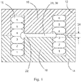
- Fig.1 shows a cross-section through a detailed specific embodiment of an inductor coil, prior to the heat sink being placed in contact with turns of the conductor.
- a first component part 12 of a ferrite material is shown at the top. This has a base portion, and a cylindrical core portion extending downwards. Outer limb portions extend downwards and are spaced from the core portion and within which turns of a conductor 18 in the form of a multi-strand wire can be located. Here six turns are shown, but there can be more or less turns than this.
- a second component part 14 again of a ferrite material is shown at the bottom.
- the core portions of the of the first component part of the second component part form a core 16.
- a centre 20 in the core is shown between the two component parts, with a centre gap has a dimension 24 that can for example be 1mm, but can be greater than or less than this.
- six turns of the multi-strand wire (or Litz wire) are shown would around the core and the gap in the core, but there can be less than or more than this.
- a gap 22 is formed around this central gap and the wire turns do not encroach into this gap 22, and as shown wire turns have been deformed to keep them out of this gap 22.
- Fig. 1 illustrates that the cross section for each turn is kept the same, but under compression free space is created to avoid the gap created by the ferrite.
- the central gap 20 is the area in which non-conductive material spacer 30 can be placed that forms the gap 22, discussed in more detail below.
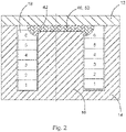
- Fig.2 shows a cross-section through a detailed specific embodiment of an inductor coil, again prior to the heat sink being placed in contact with turns of the conductor.
- a first component part 12 of a ferrite material is shown at the top. This has a base portion.
- the core 16 is spaced from the base portion of the first component part to form a gap 40 in the core.
- Fig. 2 illustrates that the cross section for each turn is kept the same, but under compression free space is created to avoid the gap created by the ferrite.
- the top gap 40 is the area in which non-conductive material spacer 50 can be placed that forms the gap 42, discussed in more detail below.
- Fig. 3 shows a detailed specific embodiment of an inductor coil, for example as shown in Fig. 1 that has a central gap 20 in the core, the conductor 18 is not shown and the heat sink is also not shown.
- the first component part 12 and the second component part 14 are shown separated from one another, and the spacer 30 is shown that also has a central hole 32.
- this figure illustrates a non-conductive insert (spacer 30) that extends over the pole length. This can be used with and without the hole in the centre 32 of the non-conductive part. This can be added during the compression or after the compression of the wires to ensure that the wires do not enter the fringing field after compression.
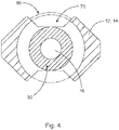
- Fig. 4 shows a representative cross-section through an inductor coil, showing a through the outer limbs of a first component part12 or a second component part 14, showing top surface of core 16 of one of the 2 component parts.
- the ring spacer 30 can be used to either compress the conductive wire 18 or to allow the bundle or strand to jump over the space containing the fringing field, and the wire could form a bump 80 outside of the core shape where space 70 may be free for the wire to enter.
- the spacer 30 by keeping the terms of the wire conductor out of the fringing field, produces heat production, improves thermal stability, and less heat is generated that has to be transferred by the heat sink.
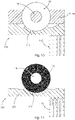
- Fig. 5 is a representation of a horizontal cross section through an inductor coil, with a heat sink 100.
- the heatsink has a first part 90 that has a series of grooves or slots and this first part is in contact and thermally bonded with the wire turnings and is in contact with a second part of the heat sink, that is itself in contact with the ferrite material of the first component 12 and/or the second component 14.
- the first part 90 of the heat sink 100 can be considered to be an eddy heat sink, in that the slots or grooves reduce the volume of magnetic permeable material adjacent to the wire turnings, and the eddy reduction heatsink 90 reduces eddy current flow within the thermally conductive heatsink, and therefore less heat is generated.
- Fig. 6 is a representation of a horizontal cross section through an inductor coil, with a heat sink 100.
- the heatsink has a first part 110 that is in contact and thermally bonded with the wire turnings and is in contact with a second part of the heat sink, that is itself in contact with the ferrite material of the first component 12 and/or the second component 14.
- the first part 110 of the heat sink 100 is thinner than the second part of the heat sink, and can again be considered to be an eddy heat sink, in that being thin the volume of magnetic permeable material adjacent to the wire turnings is reduced, and the eddy reduction heatsink 110 reduces eddy current flow within the thermally conductive heatsink, and therefore less heat is generated.
- the first part of the heat sink 90 described with respect to Fig. 5 that has grooves and slots can also be the heat sink 110 that is thinner than the second part of the heat sink as described with respect to Fig. 6 .
- the heatsink touches the ferrite material but uses a thermally conductive pad or material to provide a thermal conductive path but reducing eddy current generation by creating a low magnetics permeable space, and in this embodiment the second part of the heat sink is shown in contact with a printed circuit board (PCB) 120.
- PCB printed circuit board
- Fig. 7 is an illustration of an inductor coil and heatsink of the same nature as shown in Fig. 6 , but with the option of the heatsink having a third part 130 for improved heat transmission to ambient via the screw terminals on the heatsink or press fit of the pins or via a finned structure for heat transmission to ambient.
- Fig. 8 is an illustration of an inductor coil and heatsink of the same nature as shown in Fig. 6 (and is of a form as shown in Figs. 3-4 ), but with the embodiment of the eddy space as a combinational heat reduction part and an improved thermal path from the novel heatsink solution.
- the third part of the heat sink is in the form of a connection terminal 140 that is a thick copper wire, and that helps to transfer heat away from the inductor coil.
- Fig. 9 is an illustration of how screw terminals from heatsink base can be used to mount the inductor coil and heat sink to a printed circuit board in which the thermal path is transferred from the copper on the printed circuit board to mounting holes to a mechanical enclosure.
- "A" represents how PCB mounting holes can be utilised, where copper is connected to a ground plane and inductor coil heatsink so that the thermal path from the copper to the mechanical housing is improved, and where "B" represents holes for screwing the inductor coil base and heatsink to the PCB for an additional thermal path from the inductor coil, where copper resist can be removed to improve the heat transfer to the printed circuit board.
- Fig. 10 shows an inductor coil comprising a first part 12 and second part 14, which are combined forming a magnetic flux cage with a core 16 and a length of conductor 18 forming a coil and a heat sink, or in other words heat transfer element 100, connected at least thermally to the winding of a length of conductor 18 on a part of the conductor's 18 outer surface.
- the heat transfer element comprises a heat transmitting area 111 and a heat sink area 113 and the energy is transmitted from heat transmitting area 111 to the heat sink area 113.
- the heat sink area 113 may be a part of the element 100 designed to work as a cooling body.
- the heat sink are may also be a mounting plate, which is designed to create a good thermal contact to a heat sink.
- the material of the heat transfer element or heat sink element 100 may be aluminum.
- the heat transmitting area is in detail designed to transmit heat preferably in a radial direction away from the coil conductor 18 by modifications of the material structure on a sub millimeter scale.
- the modifications in the heat transmitting area 111 may be thin slots or laminations, which locally comprise thermally conductive layers which are extended in a radial direction but less extended in a circumferential direction related to the central axis of the core 16.
- the heat sink area 113 of the element 100 may be structured or coated in order to improve head transfer to the environment or to a cooling device. With the help of this arrangement the heat which is created in the length of conductor 18 is at least partially transferred through the heat transfer area of element 100 and transmitted to the heat sink area 113.
- Fig. 11 shows an embodiment without a magnetic flux cage. Then the magnetic field is creating magnetic fields which are even more penetrating the heat transfer element. These magnetic fields would create strong heat production based on eddy current effects in case of high alternating current frequencies in the heat transfer element if this element would have a high electrical conductivity in the heat transmitting area 111. Accordingly, the eddy current power density is reduced by use of an anisotropic or reduced electrical conductivity in the heat transmitting area, partial volume 111, which is close to the windings of the coil 18.
- Fig. 12 shows a similar embodiment without heat transfer area 113.
- the heat is transferred to an external heat sink, which is mounted thermally conductive to the heat transfer element 100.
- the material 101 may be a metal alloy.
- the heat transfer element 100 may comprise two locally different chemical element mixtures in the alloy in order to reduce electrical conductivity in the heat transfer area 111 compared to the conductivity in the heat sink area 101 or 113 (see Fig. 11 as well). In many cases the electrical and thermal conductivity of the material 101 behave similarly, then thermal conductivity is high when electrical conductivity is low.
- Fig. 13 shows an embodiment with a heat transfer element 110 between the heat transfer or heat sink element 100 and the coil conductor 18.
- the material of the heat transfer element 110 is different from the material 101 of the heat sink element 100.
- the heat transfer element 110 may be made from heat transfer material, which has a high thermal conductivity compared with other polymers but a very low electrical conductivity like an insulation material.
- the benefit of this embodiment is that the heat which is produced in the high power coil 18 can be transmitted through the transfer element 110 to the transfer and heat sink element 100 but only little eddy current losses are created in the transfer element 110 due to its low electrical conductivity. Both the thermal and the electrical conductivity of the material 101 may be high and nevertheless the eddy current losses will be low.
- the same kind of heat transfer element 110 can the heat transfer area 111 in embodiments which are shown in Figs. 10, 11 , 12 .
- the preferred heat transfer material is thermally conductive but electrically insulating material, which may consist of a silicone type material like SILPAD by Henkel material or other polymers or mixtures from polymers with particles.
- Fig 14 shows an example with a regular winding, which has no freedom of the eddy current creating space around the gap 20.
- the cross-sectional view AB shows how the thermal contact is made between transmitting element 110 and coil conductor 18 and heat sink element 100.
- Fig. 15 shows views of an exemplar heatsink.
- This heatsink is made from a single piece of extruded aluminium.
- the slots within the aluminium change the average electrical resistance of the volume of material by breaking up the circulating eddy currents.
- the second part which is away from the current field, can be a solid structure as eddy losses here are low and optimal thermal transfer can be achieved. Slots within the aluminium will be filled with thermal epoxy, this thermal epoxy will also bridge any gap between the first part with slots and the coil itself as thermal epoxy is 50 times more effective than air in most cases.
- Mounting techniques can consist of thermal transfer through PCB to case through thermal vias and mounting holes, removing and solder resist transfer from aluminium to copper and thermal via and PCB mounting holes to transfer to case.
- Other methods such as PCB cut-outs to allow the aluminium heatsink to pass through the PCB to mount directly on the casing or larger heatsink that is also providing heatsinking for any switching MOSFETS or power electronics.
- the thermal conductivity of the heat transmitting area 111 is providing an anisotropic thermal conductivity in a sub millimeter scale.
- Anisotropic means that the thermal conductivity is high due to the local structure and local material properties but the thermal conductivity is low at least in the circumferential direction according to the central axis of core 16 or in other words the thermal conductivity in the heat transfer region is low more or less tangential to the surface of the coil 18 but high in the radial direction.
- the low tangential thermal conductivity is achieved by a selection of radial laminate structure with laminated thin layers of conductive material with radial plane direction and little tangential thickness or small slots in radial direction which are filled with air or polymer or oil.
- the majority of the heat transfer element 100 is a good thermal conductor with an isotropic thermal conductivity.
- the electrical conductivity of the heat transmitting area 111 is providing an anisotropic electrical conductivity in a sub millimeter scale.
- Anisotropic means that the electrical conductivity is high due to the local structure and local material properties but the electrical conductivity is low at least in the circumferential direction according to the central axis of core 16 or in other words the electrical conductivity in the heat transfer region is low more or less tangential to the surface of the coil 18 but high in the more or less radial direction.
- the low tangential electrical conductivity is achieved by a selection of radial laminate structure with laminated thin layers of conductive material with radial plane direction and little tangential thickness or small slots in radial direction which are filled with air or polymer or oil.
- the majority of the heat transfer element 100 is a good electrical conductor with an isotropic electrical conductivity.
- the material of Element 110 may be an aluminum alloy.
- ⁇ is the resistivity of the material
- B is magnetic field strength
- d is thickness of material
- f is frequency
- f the frequency can be considered to be constant in all innovation applications.
- B the magnetic field does change between 90 and 100.
- a change in the thickness d or p is provided to achieve this.
- the resistivity pi of the material If the first part 90 and second part 110 of the heat sink 100 are made from extruded aluminum, the thickness d can be changed as the resistivity of the aluminum will remain constant if both parts are made from the same material. However, by reducing the d term between the parts, you are introducing a medium of higher electrical resistance in between to break down the eddy fields.
- Adding a thermal SIL-pad add a layer of high electrical resistance thermal transfer layer to the aluminum. To add enough distance to reduce the B field sufficiently the thickness of the SIL-Pad would need to be large and fairly poor for thermal transfer but could be an embodiment of use.
- an inductor coil and heatsink have been developed where a heatsink of thermally conductive material is connected to a coil of a plurality of turns of electrically conductive material of the inductor.
- the heatsink is connected to the coil via a thermally conductive path that reduces eddy field generation through a difference in structure and/or material within the field generating area.
- a reduction in volume can for example be achieved via a thermal conductive pad, where the thickness of the pad creates a thermal path to the heatsink but introduces a reduced volume.
- a reduction in volume of material can be achieved alternatively or additionally through removal of material in slots or grooves that reduces circulating eddy currents.
- the heatsink can have screw terminals for mechanical fixing, and pins for mechanical alignment and mechanical fixing to a medium such as a printed circuit board.
- the screw terminals can screw into an a heatsink with fin features, in which heat transfer to ambient is improved.
- inductor coils can be provided with a gap in the core, either centrally between to ferrite components or next to one of the ferrite components.
- the gap can be important in inductor design, because it can be used with respect to the control of magnetic resistance in magnetic circuit.
- eddy currents in the windings of the coil are prevented because the wire is kept away from this central gap, via a nonconductive spacer placed in the gap that is wider than the core.
- the nonconductive spacer helps to keep the conductor out of the eddy current space, and reduces heat generation.
Landscapes
- Engineering & Computer Science (AREA)
- Power Engineering (AREA)
- Chemical & Material Sciences (AREA)
- Composite Materials (AREA)
- Coils Or Transformers For Communication (AREA)
- Coils Of Transformers For General Uses (AREA)
- Transformer Cooling (AREA)
- Cooling Or The Like Of Electrical Apparatus (AREA)
- Burglar Alarm Systems (AREA)
Priority Applications (10)
| Application Number | Priority Date | Filing Date | Title |
|---|---|---|---|
| EP20204340.2A EP3992997B1 (fr) | 2020-10-28 | 2020-10-28 | Bobine d'inductance |
| HUE20204340A HUE072724T2 (hu) | 2020-10-28 | 2020-10-28 | Indukciós tekercs |
| AU2021367902A AU2021367902B2 (en) | 2020-10-28 | 2021-10-27 | An inductor coil |
| US18/033,703 US20230395299A1 (en) | 2020-10-28 | 2021-10-27 | An inductor coil |
| JP2023526149A JP7713519B2 (ja) | 2020-10-28 | 2021-10-27 | インダクタコイル |
| CN202180072870.8A CN116420204A (zh) | 2020-10-28 | 2021-10-27 | 电感线圈 |
| MX2023005102A MX2023005102A (es) | 2020-10-28 | 2021-10-27 | Una bobina inductora. |
| KR1020237018108A KR102833553B1 (ko) | 2020-10-28 | 2021-10-27 | 인덕터 코일 |
| PCT/EP2021/079755 WO2022090278A1 (fr) | 2020-10-28 | 2021-10-27 | Bobine d'induction |
| ZA2023/04348A ZA202304348B (en) | 2020-10-28 | 2023-04-12 | An inductor coil |
Applications Claiming Priority (1)
| Application Number | Priority Date | Filing Date | Title |
|---|---|---|---|
| EP20204340.2A EP3992997B1 (fr) | 2020-10-28 | 2020-10-28 | Bobine d'inductance |
Publications (3)
| Publication Number | Publication Date |
|---|---|
| EP3992997A1 true EP3992997A1 (fr) | 2022-05-04 |
| EP3992997C0 EP3992997C0 (fr) | 2025-06-11 |
| EP3992997B1 EP3992997B1 (fr) | 2025-06-11 |
Family
ID=73037772
Family Applications (1)
| Application Number | Title | Priority Date | Filing Date |
|---|---|---|---|
| EP20204340.2A Active EP3992997B1 (fr) | 2020-10-28 | 2020-10-28 | Bobine d'inductance |
Country Status (10)
| Country | Link |
|---|---|
| US (1) | US20230395299A1 (fr) |
| EP (1) | EP3992997B1 (fr) |
| JP (1) | JP7713519B2 (fr) |
| KR (1) | KR102833553B1 (fr) |
| CN (1) | CN116420204A (fr) |
| AU (1) | AU2021367902B2 (fr) |
| HU (1) | HUE072724T2 (fr) |
| MX (1) | MX2023005102A (fr) |
| WO (1) | WO2022090278A1 (fr) |
| ZA (1) | ZA202304348B (fr) |
Families Citing this family (1)
| Publication number | Priority date | Publication date | Assignee | Title |
|---|---|---|---|---|
| EP4254443A1 (fr) * | 2022-03-28 | 2023-10-04 | Schaffner EMV AG | Circuit magnétique, composant magnétique et procédé de fabrication d'un composant magnétique |
Citations (7)
| Publication number | Priority date | Publication date | Assignee | Title |
|---|---|---|---|---|
| JP2011181856A (ja) * | 2010-03-04 | 2011-09-15 | Toyota Industries Corp | 誘導機器の組立体 |
| US20130300528A1 (en) * | 2011-01-26 | 2013-11-14 | Toyota Jidosha Kabushiki Kaisha | Reactor and reactor apparatus |
| JP2014078665A (ja) * | 2012-10-12 | 2014-05-01 | Fuji Electric Co Ltd | インダクタンス部品 |
| US20140300440A1 (en) * | 2013-04-05 | 2014-10-09 | Hamilton Sundstrand Corporation | Inductor gap spacer |
| US20140327505A1 (en) * | 2011-09-02 | 2014-11-06 | Schmidhauser Ag | Inductor and Associated Production Method |
| WO2019044835A1 (fr) * | 2017-09-04 | 2019-03-07 | Ntn株式会社 | Inducteur monté sur un dissipateur thermique |
| US20200194160A1 (en) * | 2017-05-24 | 2020-06-18 | Autonetworks Technologies, Ltd. | Circuit assembly |
Family Cites Families (2)
| Publication number | Priority date | Publication date | Assignee | Title |
|---|---|---|---|---|
| JP2015207741A (ja) | 2014-04-23 | 2015-11-19 | トヨタ自動車株式会社 | リアクトル |
| JP6614210B2 (ja) * | 2017-07-27 | 2019-12-04 | Tdk株式会社 | 受電装置並びにワイヤレス電力伝送システム |
-
2020
- 2020-10-28 EP EP20204340.2A patent/EP3992997B1/fr active Active
- 2020-10-28 HU HUE20204340A patent/HUE072724T2/hu unknown
-
2021
- 2021-10-27 JP JP2023526149A patent/JP7713519B2/ja active Active
- 2021-10-27 CN CN202180072870.8A patent/CN116420204A/zh active Pending
- 2021-10-27 KR KR1020237018108A patent/KR102833553B1/ko active Active
- 2021-10-27 MX MX2023005102A patent/MX2023005102A/es unknown
- 2021-10-27 US US18/033,703 patent/US20230395299A1/en active Pending
- 2021-10-27 AU AU2021367902A patent/AU2021367902B2/en active Active
- 2021-10-27 WO PCT/EP2021/079755 patent/WO2022090278A1/fr not_active Ceased
-
2023
- 2023-04-12 ZA ZA2023/04348A patent/ZA202304348B/en unknown
Patent Citations (7)
| Publication number | Priority date | Publication date | Assignee | Title |
|---|---|---|---|---|
| JP2011181856A (ja) * | 2010-03-04 | 2011-09-15 | Toyota Industries Corp | 誘導機器の組立体 |
| US20130300528A1 (en) * | 2011-01-26 | 2013-11-14 | Toyota Jidosha Kabushiki Kaisha | Reactor and reactor apparatus |
| US20140327505A1 (en) * | 2011-09-02 | 2014-11-06 | Schmidhauser Ag | Inductor and Associated Production Method |
| JP2014078665A (ja) * | 2012-10-12 | 2014-05-01 | Fuji Electric Co Ltd | インダクタンス部品 |
| US20140300440A1 (en) * | 2013-04-05 | 2014-10-09 | Hamilton Sundstrand Corporation | Inductor gap spacer |
| US20200194160A1 (en) * | 2017-05-24 | 2020-06-18 | Autonetworks Technologies, Ltd. | Circuit assembly |
| WO2019044835A1 (fr) * | 2017-09-04 | 2019-03-07 | Ntn株式会社 | Inducteur monté sur un dissipateur thermique |
Also Published As
| Publication number | Publication date |
|---|---|
| HUE072724T2 (hu) | 2025-12-28 |
| CN116420204A (zh) | 2023-07-11 |
| US20230395299A1 (en) | 2023-12-07 |
| JP7713519B2 (ja) | 2025-07-25 |
| WO2022090278A1 (fr) | 2022-05-05 |
| AU2021367902A1 (en) | 2023-05-18 |
| MX2023005102A (es) | 2023-08-07 |
| ZA202304348B (en) | 2023-12-20 |
| KR20230093511A (ko) | 2023-06-27 |
| EP3992997C0 (fr) | 2025-06-11 |
| JP2023547212A (ja) | 2023-11-09 |
| EP3992997B1 (fr) | 2025-06-11 |
| KR102833553B1 (ko) | 2025-07-11 |
| AU2021367902B2 (en) | 2023-12-07 |
Similar Documents
| Publication | Publication Date | Title |
|---|---|---|
| US7920039B2 (en) | Thermally enhanced magnetic transformer | |
| US6844802B2 (en) | Parallel core electromagnetic device | |
| EP2444983A2 (fr) | Composant magnétique refroidi par liquides doté d'un refroidissement indirect pour applications haute fréquence et haute puissance | |
| US7158001B2 (en) | Choke coil and electronic device using the same | |
| CN111354543A (zh) | 磁性组件及电源模块 | |
| CN1466679A (zh) | 电子变压器/电感器器件及其制造方法 | |
| WO2009029743A1 (fr) | Ensemble d'enroulement de moteur | |
| JP2013526020A (ja) | 一体型プレーナトランスおよび母線 | |
| CN105706196A (zh) | 电磁感应设备 | |
| AU2021367902B2 (en) | An inductor coil | |
| TW202242922A (zh) | 電源變壓器的平面繞組結構 | |
| KR101821177B1 (ko) | 방열성이 우수한 박막형 변압기 | |
| CN224036192U (zh) | 具有改进的制冷的电磁装置 | |
| US11778773B2 (en) | Choke structure with water cooling | |
| US7088211B2 (en) | Space saving surface-mounted inductors | |
| CN109346296A (zh) | 变压器 | |
| EP2568484A1 (fr) | Dispositif électromagnétique possédant une enveloppe polymère | |
| CN221708495U (zh) | 一种用于高频变压器的外壳结构、高频变压器及用电设备 | |
| JP5936874B2 (ja) | 電源モジュール | |
| CN210956373U (zh) | 一种磁件 | |
| JP2019197779A (ja) | リアクトル | |
| JP2026510489A (ja) | 冷却機能を改善した電磁装置 | |
| JPH04229906A (ja) | 導電体 | |
| WO2026052346A1 (fr) | Élément de noyau pour composant inductif et composant inductif | |
| CN117546257A (zh) | 电气设备布置 |
Legal Events
| Date | Code | Title | Description |
|---|---|---|---|
| PUAI | Public reference made under article 153(3) epc to a published international application that has entered the european phase |
Free format text: ORIGINAL CODE: 0009012 |
|
| STAA | Information on the status of an ep patent application or granted ep patent |
Free format text: STATUS: THE APPLICATION HAS BEEN PUBLISHED |
|
| AK | Designated contracting states |
Kind code of ref document: A1 Designated state(s): AL AT BE BG CH CY CZ DE DK EE ES FI FR GB GR HR HU IE IS IT LI LT LU LV MC MK MT NL NO PL PT RO RS SE SI SK SM TR |
|
| STAA | Information on the status of an ep patent application or granted ep patent |
Free format text: STATUS: REQUEST FOR EXAMINATION WAS MADE |
|
| 17P | Request for examination filed |
Effective date: 20221102 |
|
| RBV | Designated contracting states (corrected) |
Designated state(s): AL AT BE BG CH CY CZ DE DK EE ES FI FR GB GR HR HU IE IS IT LI LT LU LV MC MK MT NL NO PL PT RO RS SE SI SK SM TR |
|
| GRAP | Despatch of communication of intention to grant a patent |
Free format text: ORIGINAL CODE: EPIDOSNIGR1 |
|
| STAA | Information on the status of an ep patent application or granted ep patent |
Free format text: STATUS: GRANT OF PATENT IS INTENDED |
|
| INTG | Intention to grant announced |
Effective date: 20250109 |
|
| GRAS | Grant fee paid |
Free format text: ORIGINAL CODE: EPIDOSNIGR3 |
|
| GRAA | (expected) grant |
Free format text: ORIGINAL CODE: 0009210 |
|
| STAA | Information on the status of an ep patent application or granted ep patent |
Free format text: STATUS: THE PATENT HAS BEEN GRANTED |
|
| AK | Designated contracting states |
Kind code of ref document: B1 Designated state(s): AL AT BE BG CH CY CZ DE DK EE ES FI FR GB GR HR HU IE IS IT LI LT LU LV MC MK MT NL NO PL PT RO RS SE SI SK SM TR |
|
| REG | Reference to a national code |
Ref country code: GB Ref legal event code: FG4D |
|
| REG | Reference to a national code |
Ref country code: CH Ref legal event code: EP |
|
| REG | Reference to a national code |
Ref country code: IE Ref legal event code: FG4D |
|
| REG | Reference to a national code |
Ref country code: DE Ref legal event code: R096 Ref document number: 602020052552 Country of ref document: DE |
|
| U01 | Request for unitary effect filed |
Effective date: 20250703 |
|
| U07 | Unitary effect registered |
Designated state(s): AT BE BG DE DK EE FI FR IT LT LU LV MT NL PT RO SE SI Effective date: 20250710 |
|
| PG25 | Lapsed in a contracting state [announced via postgrant information from national office to epo] |
Ref country code: ES Free format text: LAPSE BECAUSE OF FAILURE TO SUBMIT A TRANSLATION OF THE DESCRIPTION OR TO PAY THE FEE WITHIN THE PRESCRIBED TIME-LIMIT Effective date: 20250611 |
|
| PG25 | Lapsed in a contracting state [announced via postgrant information from national office to epo] |
Ref country code: NO Free format text: LAPSE BECAUSE OF FAILURE TO SUBMIT A TRANSLATION OF THE DESCRIPTION OR TO PAY THE FEE WITHIN THE PRESCRIBED TIME-LIMIT Effective date: 20250911 Ref country code: GR Free format text: LAPSE BECAUSE OF FAILURE TO SUBMIT A TRANSLATION OF THE DESCRIPTION OR TO PAY THE FEE WITHIN THE PRESCRIBED TIME-LIMIT Effective date: 20250912 |
|
| PG25 | Lapsed in a contracting state [announced via postgrant information from national office to epo] |
Ref country code: HR Free format text: LAPSE BECAUSE OF FAILURE TO SUBMIT A TRANSLATION OF THE DESCRIPTION OR TO PAY THE FEE WITHIN THE PRESCRIBED TIME-LIMIT Effective date: 20250611 |
|
| PG25 | Lapsed in a contracting state [announced via postgrant information from national office to epo] |
Ref country code: RS Free format text: LAPSE BECAUSE OF FAILURE TO SUBMIT A TRANSLATION OF THE DESCRIPTION OR TO PAY THE FEE WITHIN THE PRESCRIBED TIME-LIMIT Effective date: 20250911 |
|
| U20 | Renewal fee for the european patent with unitary effect paid |
Year of fee payment: 6 Effective date: 20251029 |
|
| PGFP | Annual fee paid to national office [announced via postgrant information from national office to epo] |
Ref country code: HU Payment date: 20251127 Year of fee payment: 6 |
|
| REG | Reference to a national code |
Ref country code: HU Ref legal event code: AG4A Ref document number: E072724 Country of ref document: HU |
|
| PG25 | Lapsed in a contracting state [announced via postgrant information from national office to epo] |
Ref country code: IS Free format text: LAPSE BECAUSE OF FAILURE TO SUBMIT A TRANSLATION OF THE DESCRIPTION OR TO PAY THE FEE WITHIN THE PRESCRIBED TIME-LIMIT Effective date: 20251011 |
|
| PGFP | Annual fee paid to national office [announced via postgrant information from national office to epo] |
Ref country code: GB Payment date: 20251120 Year of fee payment: 6 |
|
| PG25 | Lapsed in a contracting state [announced via postgrant information from national office to epo] |
Ref country code: SM Free format text: LAPSE BECAUSE OF FAILURE TO SUBMIT A TRANSLATION OF THE DESCRIPTION OR TO PAY THE FEE WITHIN THE PRESCRIBED TIME-LIMIT Effective date: 20250611 |
|
| PG25 | Lapsed in a contracting state [announced via postgrant information from national office to epo] |
Ref country code: CZ Free format text: LAPSE BECAUSE OF FAILURE TO SUBMIT A TRANSLATION OF THE DESCRIPTION OR TO PAY THE FEE WITHIN THE PRESCRIBED TIME-LIMIT Effective date: 20250611 |
|
| PG25 | Lapsed in a contracting state [announced via postgrant information from national office to epo] |
Ref country code: PL Free format text: LAPSE BECAUSE OF FAILURE TO SUBMIT A TRANSLATION OF THE DESCRIPTION OR TO PAY THE FEE WITHIN THE PRESCRIBED TIME-LIMIT Effective date: 20250611 |
|
| PG25 | Lapsed in a contracting state [announced via postgrant information from national office to epo] |
Ref country code: SK Free format text: LAPSE BECAUSE OF FAILURE TO SUBMIT A TRANSLATION OF THE DESCRIPTION OR TO PAY THE FEE WITHIN THE PRESCRIBED TIME-LIMIT Effective date: 20250611 |
|
| PLBE | No opposition filed within time limit |
Free format text: ORIGINAL CODE: 0009261 |
|
| STAA | Information on the status of an ep patent application or granted ep patent |
Free format text: STATUS: NO OPPOSITION FILED WITHIN TIME LIMIT |
|
| REG | Reference to a national code |
Ref country code: CH Ref legal event code: L10 Free format text: ST27 STATUS EVENT CODE: U-0-0-L10-L00 (AS PROVIDED BY THE NATIONAL OFFICE) Effective date: 20260423 |