EP3993193B1 - Connecteur enfichable haute tension à isolation gazeuse, comportant une enveloppe sous pression, une première partie de l'enveloppe formant un connecteur femelle et une seconde partie de l'enveloppe formant un connecteur mâle - Google Patents
Connecteur enfichable haute tension à isolation gazeuse, comportant une enveloppe sous pression, une première partie de l'enveloppe formant un connecteur femelle et une seconde partie de l'enveloppe formant un connecteur mâle Download PDFInfo
- Publication number
- EP3993193B1 EP3993193B1 EP21200434.5A EP21200434A EP3993193B1 EP 3993193 B1 EP3993193 B1 EP 3993193B1 EP 21200434 A EP21200434 A EP 21200434A EP 3993193 B1 EP3993193 B1 EP 3993193B1
- Authority
- EP
- European Patent Office
- Prior art keywords
- enclosure
- gas
- electrical
- plug connection
- voltage plug
- Prior art date
- Legal status (The legal status is an assumption and is not a legal conclusion. Google has not performed a legal analysis and makes no representation as to the accuracy of the status listed.)
- Active
Links
Images
Classifications
-
- H—ELECTRICITY
- H02—GENERATION; CONVERSION OR DISTRIBUTION OF ELECTRIC POWER
- H02B—BOARDS, SUBSTATIONS OR SWITCHING ARRANGEMENTS FOR THE SUPPLY OR DISTRIBUTION OF ELECTRIC POWER
- H02B13/00—Arrangement of switchgear in which switches are enclosed in, or structurally associated with, a casing, e.g. cubicle
- H02B13/02—Arrangement of switchgear in which switches are enclosed in, or structurally associated with, a casing, e.g. cubicle with metal casing
- H02B13/035—Gas-insulated switchgear
- H02B13/0358—Connections to in or out conductors
-
- H—ELECTRICITY
- H02—GENERATION; CONVERSION OR DISTRIBUTION OF ELECTRIC POWER
- H02G—INSTALLATION OF ELECTRIC CABLES OR LINES, OR OF COMBINED OPTICAL AND ELECTRIC CABLES OR LINES
- H02G15/00—Cable fittings
- H02G15/20—Cable fittings for cables filled with or surrounded by gas or oil
- H02G15/24—Cable junctions
-
- H—ELECTRICITY
- H01—ELECTRIC ELEMENTS
- H01H—ELECTRIC SWITCHES; RELAYS; SELECTORS; EMERGENCY PROTECTIVE DEVICES
- H01H1/00—Contacts
- H01H1/58—Electric connections to or between contacts; Terminals
- H01H1/5822—Flexible connections between movable contact and terminal
-
- H—ELECTRICITY
- H02—GENERATION; CONVERSION OR DISTRIBUTION OF ELECTRIC POWER
- H02G—INSTALLATION OF ELECTRIC CABLES OR LINES, OR OF COMBINED OPTICAL AND ELECTRIC CABLES OR LINES
- H02G5/00—Installations of bus-bars
- H02G5/002—Joints between bus-bars for compensating thermal expansion
Definitions
- the invention relates to a gas-insulated high-voltage plug connection, having a pressure-conducting enclosure, wherein a first part of the enclosure forms a connection socket and a second part of the enclosure forms a plug, wherein the first and the second part of the enclosure each accommodate at least one electrical conductor in the enclosure, wherein the electrical conductors each have a contact surface at the end.
- one of the electrical conductors has a region with a high degree of flexibility due to suitably running individual conductors, wherein the contact surface of this electrical conductor is mounted so that it can move by means of a length adjustment element.
- Known high-voltage plug connections require a large installation space due to normative requirements regarding clearance and creepage distances, unless they are filled with an insulating gas.
- Known high-voltage plug connections filled with insulating gas are welded constructions manufactured as individual pieces with the resulting manufacturing tolerances. So that such a plug and socket can be easily connected to one another in a hermetically sealed and electrically conductive manner despite the manufacturing tolerances, they are manufactured in pairs, individualized or adapted to one another, which means that a plug only functions reliably with an associated socket.
- a high-voltage module such as a transformer
- a replacement module because a gas-insulated high-voltage plug connection cannot be reliably created with a different plug-socket combination.
- An explosion-proof connector which has a socket and a plug.
- the socket there are two clamping contacts, into which two Pin contacts can be inserted.
- the socket and plug are inserted into one another and the pin contacts are then moved into the terminal contacts via the spindle drive.
- the conductors running inside the plug have a slack which decreases when the plug contacts move.
- the connector also has several seals.
- the DE 693 06 886 T2 also describes an explosion-proof connector for use in explosive, i.e. combustible and flammable gas atmospheres.
- the connector in turn has a socket and a plug, with the socket having two base contacts and the plug having two pin contacts.
- the base contacts arranged at the end of an inner cylinder of the socket are moved into the plug by a drive device until the pin contacts engage with the base contacts.
- an electrical conductor connected to the base contacts and running inside the inner cylinder of the socket is moved together with the inner cylinder so that no bending stress acts on the conductor.
- the connector also has an inlet and an outlet opening through which a clean gas is passed before the pin contacts are coupled to the base contacts in order to ventilate the interior of the connector, thus removing any explosive gases present inside.
- An electrical connection device for conductors which has wall-like contact partners to which the conductors to be connected are attached.
- a gap between the contact partners is sealed by a circumferential seal and, after the contact partners have been connected, has several interlocking concentric ring formations, by means of which a high degree of nesting of the gap is achieved.
- a moisture-absorbing material is also introduced into the gap.
- the WO 2017 / 162 392 A1 describes a gas-insulated high-voltage plug connection with a pressure vessel, wherein a first part of the pressure vessel has a connection socket and a second part of the pressure vessel has a plug.
- an electrical conductor or several sections of an electrical conductor are arranged, wherein the electrical conductors each have a contact surface
- One of the electrical conductors has a region with a high degree of flexibility due to a section made up of several layers of electrically conductive strips arranged one above the other. This allows the conductor to be mobile, so that the contact surface of this electrical conductor can be adjusted via a swivel arm arranged in the second part of the pressure vessel.
- FR 2 882 852 A1 is a high-voltage plug connection with a high-voltage switch which has two contacts arranged in a housing, wherein at least one of the contacts is designed to be movable via a mechanism.
- a circuit breaker is also known, in particular for use in gas-insulated high-voltage substations.
- the isolating device is designed to electrically separate a first section of an electrical circuit from a second section of the circuit.
- the isolating device comprises a contact pair with at least two contacts, one of which is a movable contact.
- the contact pair accordingly has an open state and a closed state and a flexible conductor which is attached to the movable contact at one end. This is also attached to one of the parts of an electrical circuit at its other end.
- the conductor is designed in particular as a flexible tube which is electrically conductive at least on one surface section and has a bending stiffness which is low enough to allow the tube to be bent without kinking.
- the tube has a torsional stiffness which is high enough to allow the tube to have a substantially reproducible shape and position at least when the contact pair is closed.
- a high-voltage bushing for connecting transformers filled with an insulating liquid to cables or switchgear filled with sulphur hexafluoride.
- a safety chamber is arranged between the transformer and the connected part of the system, whereby this safety chamber, filled with an insulating liquid, is sealed off on both sides in the axial direction by nozzles for the conductor ends and is radially closed by a bellows that can be pushed together in the axial direction.
- a flexible conductor made of twisted individual strands is arranged inside the bellows and is designed to be detachable via screw connections.
- the conductor can be removed via channels on a nozzle and After loosening the bellows, the flexible conductor that galvanically connects the conductor ends can be removed without changing the position of the transformer and the system part connected to it.
- the US 3 902 001 A an elongated, cylindrical shield against corona discharges is known, which encloses the connection between adjacent conductor elements of a gas-insulated energy transmission system.
- the shield is supported on one of the conductor elements by a flexible spring arrangement which allows a considerable degree of misalignment between the shield and the opposite conductor element during the assembly process.
- the US 2016 / 0 133 359 A1 also discloses an insulation device with two electrical contacts, wherein the contacts are each connected to an electrical conductor.
- the contacts themselves are in turn each surrounded by a plate-shaped insulation disk, which forms a flange in sections. When the electrical contacts are assembled and come into contact, the two insulation disks form a fluid-tight space around the two electrical contacts.
- the invention is based on the object of producing a high-voltage plug connection which, on the one hand, is particularly compact and, on the other hand, enables a simple and reliable connection creation of high-voltage plug connections, even when using plugs and sockets which are not adapted to one another.
- a gas-insulated high-voltage plug connection is provided with a pressure-conducting enclosure comprising at least two parts, wherein a first part of the enclosure has or encloses a connection socket and a second part of the enclosure has or encloses a plug.
- the first and second parts of the enclosure each accommodate at least one electrical conductor in the enclosure.
- the electrical conductors each have a contact surface at their ends, which are connected to one another when the high-voltage plug connection is created. brought into contact.
- the contact surfaces can be designed, for example, as a wire end ferrule.
- One of the electrical conductors has a region with a high degree of flexibility within the enclosure by suitably extending individual conductors, the contact surface of this electrical conductor being mounted so that it can move by means of a length adjustment element.
- the enclosure consists of housing parts and can form a hermetically sealed space within the enclosure with seals and, for example, flanges that serve to screw the housing parts together.
- the housing parts are in particular welded constructions or bodies made of composite materials with a high-tensile fiber fabric and preferably have a cylindrical geometry.
- the enclosure has an inlet valve and an outlet valve for flushing with a gas, in particular a dried insulating gas.
- Individual conductors are understood to be uninsulated, isolated conductors, i.e. wires or strands, which can form a power cable, for example.
- Individual conductors that are suitably positioned to achieve high flexibility are understood to mean any arrangement of individual conductors within the enclosure that makes it possible to significantly increase or decrease the flexible area in the longitudinal direction of the electrical conductor during assembly, for example by at least 10% or preferably 20% of the length of the flexible area.
- the first part and the second part of the enclosure are connected to one another in a pressure-tight manner, for example by screwing them together. Subsequently, gas is let in through an inlet valve to dry the enclosure and is let out through an outlet valve, whereby after the desired residual moisture has been reached, the outlet valve is first closed and an operating pressure is set in the enclosure. Furthermore, the contact surface of one electrical conductor is moved against the contact surface of the other electrical conductor until the desired contact force is set in order to create an electrical connection with low contact resistance.
- the electrical conductors are power cables that are fed into the enclosure through cable bulkheads. This enables a hermetically sealed feedthrough into the enclosure using standard components. When the electrical power is fed to the high-voltage plug connection using a power cable, adapters and another connection point are not required.
- the individual conductors are also a part of the power cable that is guided through the cable bulkhead, i.e. the individual conductors are worked out of the power cable and separated. This means that there is no need to create a connection between the individual conductors and the power cable, which makes the high-voltage plug connection easier to produce and more compact.
- individual conductors can be used to form a flexible region by guiding the individual conductors preferably along at least one support body, which is variable in length in the direction of travel of a friction bridge and/or perpendicular thereto and more preferably has a wave-shaped geometry, such as a bellows. A movement of the contact surface of the electrical conductor over a larger distance, such as 10 cm, by means of a small force is made possible.
- the contact surface is moved by the length adjustment element, wherein the length adjustment element is preferably a linear drive, in particular at least one hydraulic cylinder.
- the hydraulic cylinder is preferably fed by means of a hydraulic line guided into the enclosure, wherein the hydraulic fluid is conveyed by means of a hydraulic pump, such as a hand-operated hydraulic pump.
- a hydraulic pump such as a hand-operated hydraulic pump.
- Preferred embodiments provide a plurality, such as two, three or four hydraulic cylinders, since this enables a particularly simple arrangement of the hydraulic cylinders and design of the length adjustment element.
- the linear drive can alternatively be designed as a thread drive that is driven by electrical or mechanical energy fed into the enclosure. High contact forces can thus be achieved easily, even without the use of hydraulics.
- the length adjustment element preferably has an energy storage device that counteracts the drop in contact forces.
- the energy storage device can be implemented as an elastic element in the force flow or in the hydraulic system and receives its energy when the contact force is generated. The generation and permanent securing of a high contact force in the hermetically sealed enclosure is made possible in a simple manner.
- the length adjustment element is preferably connected to an electrical conductor by means of an insulating friction bridge, so that the length adjustment element is not at the electrical potential of the high-current connection and does not need to have electrical insulation for enclosing. This enables a particularly simple and compact design of the high-voltage plug connection.
- the length adjustment element has an electrical insulation to the electrical conductor, which is located between the length adjustment element and the electrical conductor regardless of the position of the length adjustment element, so that the necessary distance due to the insulation distances to be maintained with insulating gas can be undercut and a particularly compact design of the gas-insulated high-voltage plug connection can be achieved.
- the inside of the pressure-bearing enclosure can be coated or lined with an electrically insulating, preferably corrugated material in order to increase the dielectric strength of the high-voltage plug connection and to increase the resistance of the leakage current path via the length adjustment element.
- the enclosure preferably has a drying agent, in particular zeolite, which absorbs residual moisture that is in the enclosure after the operating pressure has been set. This prevents water from precipitating out of the insulating gas at low temperatures and leading to a deterioration in the electrical insulation or to increased oxidation of the components.
- the drying agent In order not to reduce the drying ability of the drying agent before the enclosure is closed, the drying agent must be hermetically sealed until the enclosure is closed.
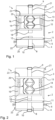
- Figure 1 shows a gas-insulated high-voltage plug connection 1 with a two-part pressure-bearing enclosure 2, consisting of a first part of the enclosure 2, which forms a connection socket 3, and a second part of the enclosure, which forms a plug 4.
- the connection socket 3 has a flange 5 and the plug 4 has a flange 6, the flanges 5, 6 serving to screw the connection socket 3 to the plug 4.
- the pressure-bearing enclosure 2 is hermetically sealed; for this purpose, the connection socket 3 and the plug 4 have sealing surfaces.
- Electrical conductors 7, 8 are implemented in the form of power cables, which are introduced into the enclosure 2 through sealing cable bulkheads 9, 10.
- the power cable guided into the plug 4 is guided through the insulated housing connection to an insulation plate 11, which is mechanically connected to the power cable and absorbs forces acting on the power cable and diverts them into the plug 4.
- the power cable Above the insulation plate 11, the power cable has a contact surface 12 which is designed in the form of a wire end ferrule which, in the state shown, has no contact with the connection socket 3.
- the electrical conductor 7 in the form of a power cable is led into the connection socket 3 from the cable bulkhead 9 through the insulated housing connection to an insulation plate 13, which is mechanically connected to the power cable and absorbs forces acting on the power cable and diverts them into the connection socket 3. Beyond the insulation plate 13, the power cable has no insulation.
- the individual conductors 14 of the power cable are separated and laid on the outer contour of a support body 15.
- the support body 15 is rotationally symmetrical and has a wave-shaped contour in its longitudinal direction. It is made of a flexible material, such as silicone.
- the support body 15 therefore has a high degree of flexibility in its longitudinal and transverse direction. A flexible area 16 of the electrical conductor is thus realized.
- the individual conductors 14 are guided from the support body 15 through an insulation plate 17 and end in a contact surface 18, which is designed as a wire end ferrule.
- the wire end ferrule is connected to the insulation plate 17, which directs the forces acting on the wire end ferrule into the connection socket 3 via a length adjustment element 19, which is implemented by two hydraulic cylinders, by means of the insulation plate 13.
- the enclosure 2 has several drying agents 20.
Landscapes
- Engineering & Computer Science (AREA)
- Power Engineering (AREA)
- Connector Housings Or Holding Contact Members (AREA)
Claims (7)
- Connexion à enfichage à haute tension à isolation gazeuse (1), possédant un encapsulage (2) conduisant la pression, une première partie de l'encapsulage (2) formant une douille de connexion (3) et une deuxième partie de l'encapsulage (2) formant un connecteur (4), la première et la deuxième partie de l'encapsulage (2) accueillant respectivement au moins un conducteur électrique (7, 8) dans l'encapsulage (2), les conducteurs électriques (7, 8) possédant, du côté de l'extrémité, respectivement une surface de contact (12, 18) et l'un des conducteurs électriques (7, 8) possédant, par des conducteurs individuels (14) qui suivent un tracé approprié, une zone (16) ayant une haute flexibilité, la surface de contact (12, 18) de ce conducteur électrique (7, 8) étant supportée mobile au moyen d'un élément de positionnement en longueur (19), caractérisée en ce que les conducteurs électriques (7, 8) sont des câbles électriques, qui sont amenés dans l'encapsulage (2) à travers des cloisons étanches pour câble (9, 10), la zone flexible (16) composée de conducteurs individuels (14) étant une zone partielle du câble électrique qui est guidée à travers la cloison étanche pour câble (9).
- Connexion à enfichage à haute tension à isolation gazeuse (1) selon la revendication 1, caractérisée en ce que les conducteurs individuels (14) dans la zone flexible suivent un tracé le long d'au moins un corps de soutien (15), lequel est de longueur variable de préférence dans la direction de déplacement de l'élément de positionnement en longueur (19) et/ou perpendiculairement à celle-ci et plus préférablement présente une géométrie ondulée.
- Connexion à enfichage à haute tension à isolation gazeuse (1) selon au moins l'une des revendications précédentes, caractérisée en ce que l'élément de positionnement en longueur (19) est un mécanisme d'entraînement linéaire, notamment au moins un vérin hydraulique, lequel est de préférence alimenté au moyen d'une conduite hydraulique (23) amenée dans l'encapsulage (2) .
- Connexion à enfichage à haute tension à isolation gazeuse (1) selon au moins l'une des revendications précédentes, caractérisée en ce que le mécanisme d'entraînement linéaire est un mécanisme d'entraînement à filetage, lequel est entraîné au moyen d'énergie électrique ou mécanique qui est conduite dans l'encapsulage (2).
- Connexion à enfichage à haute tension à isolation gazeuse (1) selon au moins l'une des revendications précédentes, caractérisée en ce que l'élément de positionnement en longueur (19) est relié au conducteur électrique (7, 8) au moyen d'une plaque isolante (17).
- Connexion à enfichage à haute tension à isolation gazeuse (1) selon au moins l'une des revendications précédentes, caractérisée en ce que l'élément de positionnement en longueur (19) possède une isolation électrique par rapport au conducteur électrique (7, 8).
- Connexion à enfichage à haute tension à isolation gazeuse (1) selon au moins l'une des revendications précédentes, caractérisée en ce que l'encapsulage (2) possède un agent dessiccateur (20), notamment de la zéolithe.
Applications Claiming Priority (1)
| Application Number | Priority Date | Filing Date | Title |
|---|---|---|---|
| DE102020128508.6A DE102020128508A1 (de) | 2020-10-29 | 2020-10-29 | Gasisolierte Hochspannungssteckverbindung, aufweisend eine druckführende Umschließung, wobei ein erster Teil der Umschließung eine Verbindungsbuchse und ein zweiter Teil der Umschließung einen Stecker ausbildet |
Publications (3)
| Publication Number | Publication Date |
|---|---|
| EP3993193A1 EP3993193A1 (fr) | 2022-05-04 |
| EP3993193B1 true EP3993193B1 (fr) | 2024-04-17 |
| EP3993193C0 EP3993193C0 (fr) | 2024-04-17 |
Family
ID=78269584
Family Applications (1)
| Application Number | Title | Priority Date | Filing Date |
|---|---|---|---|
| EP21200434.5A Active EP3993193B1 (fr) | 2020-10-29 | 2021-10-01 | Connecteur enfichable haute tension à isolation gazeuse, comportant une enveloppe sous pression, une première partie de l'enveloppe formant un connecteur femelle et une seconde partie de l'enveloppe formant un connecteur mâle |
Country Status (2)
| Country | Link |
|---|---|
| EP (1) | EP3993193B1 (fr) |
| DE (1) | DE102020128508A1 (fr) |
Family Cites Families (9)
| Publication number | Priority date | Publication date | Assignee | Title |
|---|---|---|---|---|
| US3902001A (en) * | 1974-08-28 | 1975-08-26 | Ite Imperial Corp | Floating corona shield |
| DE2746566C3 (de) * | 1977-10-17 | 1981-11-26 | Transformatoren Union Ag, 7000 Stuttgart | Hochspannungsdurchführung zum Anschluß von mit Isolierflüssigkeit gefüllten Transformatoren an SF↓6↓-isolierte Kabel oder Schaltanlagen |
| FR2672440B1 (fr) | 1991-02-01 | 1995-04-14 | Alsthom Gec | Connexion electrique notamment pour poste electrique modulaire moyenne tension. |
| DE69306886T2 (de) | 1992-09-11 | 1997-05-07 | Toyo Engineering Corp | Automatische Einsteckeinrichtung |
| FR2870635B1 (fr) * | 2004-05-18 | 2006-07-14 | Areva T & D Ag | Dispositif de sectionnement d'energie electrique. |
| FR2882852B1 (fr) * | 2005-03-02 | 2007-04-20 | Areva T & D Sa | Connexion d'une chambre de coupure d'un appareil de commutation blinde |
| DE102013211133A1 (de) * | 2013-06-14 | 2014-12-18 | Siemens Aktiengesellschaft | Isolationssystem sowie Montageverfahren eines Isolationssystems |
| DE102016204668A1 (de) * | 2016-03-22 | 2017-09-28 | Siemens Aktiengesellschaft | Phasenleiteranordnung |
| CN110048268A (zh) | 2019-04-29 | 2019-07-23 | 黄烁伊 | 封闭插接式电源防爆连接器 |
-
2020
- 2020-10-29 DE DE102020128508.6A patent/DE102020128508A1/de active Pending
-
2021
- 2021-10-01 EP EP21200434.5A patent/EP3993193B1/fr active Active
Also Published As
| Publication number | Publication date |
|---|---|
| EP3993193A1 (fr) | 2022-05-04 |
| EP3993193C0 (fr) | 2024-04-17 |
| DE102020128508A1 (de) | 2022-05-05 |
Similar Documents
| Publication | Publication Date | Title |
|---|---|---|
| DE69802414T2 (de) | Elektrische verbindungsvorrichtung mit einem fluidischen isolierstoff | |
| EP0744803A2 (fr) | Sectionneur pour une installation de commutation à haute tension, blindé et à isolation gazeuse | |
| DE102009014334B4 (de) | Stromanschlusseinrichtung für Behälter | |
| EP0199891B2 (fr) | Dispositif de connexion pour des installations de commutation à isolation gazeuse | |
| EP2073216B1 (fr) | Module de traversée électrique et son procédé de fabrication | |
| EP0438769B1 (fr) | Dispositif et procédé pour la connexion d'installations de commutation à isolement gazeux placés dans des boîtiers séparés | |
| WO2016066522A1 (fr) | Dispositif anti-déflagration | |
| WO2005074074A2 (fr) | Module de disjoncteur isole a l'aide de gaz sous pression et dispositif a traversee correspondant | |
| EP0919076A1 (fr) | Installation a haute tension isolee par gas, encapsulee et pourvue d'un composant de connexion cloisonne | |
| EP3993193B1 (fr) | Connecteur enfichable haute tension à isolation gazeuse, comportant une enveloppe sous pression, une première partie de l'enveloppe formant un connecteur femelle et une seconde partie de l'enveloppe formant un connecteur mâle | |
| WO2004034534A2 (fr) | Couplage des barres pour une installation de distribution etanche au gaz | |
| EP1657795B1 (fr) | Connecteur enfichable de câble d'un dispositif de connexion enfichable pour la technologie de la moyenne et de l'haute tension | |
| DE1230115B (de) | Hochspannungsschaltanlage mit druckgasisoliertem Schaltgeraet | |
| DE19856025C2 (de) | Kompakte Übergangsmuffe | |
| EP0073423B1 (fr) | Element de liaison d'un conducteur isolé par un corps solide | |
| EP3699934A1 (fr) | Traversée électrique pour boîtier de pression | |
| DE10129568B4 (de) | Hochstromschiene | |
| DE102018201160A1 (de) | Hochspannungsdurchführung, elektrisches Gerät mit Hochspannungsdurchführung und Verfahren zur Herstellung des elektrischen Gerätes | |
| EP3993194A1 (fr) | Contact haute tension pour une connexion haute tension tolérable aux imperfections géométriques, ainsi que connecteur enfichable haute tension doté d'un tel contact haute tension | |
| DE19959450B4 (de) | Elektrische Steckverbindung, welche sich während der Montage der isoliergasbefüllten Schaltanlagenkomponenten selbsttätig mit Isoliergas befüllt | |
| EP3665710B1 (fr) | Dispositif destiné à être raccordé à un réseau à haute tension avec une pluralité de transformateurs monophasés | |
| EP4687236A1 (fr) | Compensateur coulissant avec bague de serrage | |
| DE2659234B2 (de) | Kabelgarnitur zum Anschluß eines geschirmten, kunststoffisolierten Starkstromkabels an ein elektrisches Gerät | |
| EP2668703B1 (fr) | Ensemble permettant le couplage isolé de composants électroconducteurs dans un appareillage de connexion | |
| WO2026053022A1 (fr) | Dispositif enfichable et appareil de connexion enfichable comprenant un tel dispositif enfichable |
Legal Events
| Date | Code | Title | Description |
|---|---|---|---|
| PUAI | Public reference made under article 153(3) epc to a published international application that has entered the european phase |
Free format text: ORIGINAL CODE: 0009012 |
|
| STAA | Information on the status of an ep patent application or granted ep patent |
Free format text: STATUS: THE APPLICATION HAS BEEN PUBLISHED |
|
| AK | Designated contracting states |
Kind code of ref document: A1 Designated state(s): AL AT BE BG CH CY CZ DE DK EE ES FI FR GB GR HR HU IE IS IT LI LT LU LV MC MK MT NL NO PL PT RO RS SE SI SK SM TR |
|
| STAA | Information on the status of an ep patent application or granted ep patent |
Free format text: STATUS: REQUEST FOR EXAMINATION WAS MADE |
|
| 17P | Request for examination filed |
Effective date: 20221025 |
|
| RBV | Designated contracting states (corrected) |
Designated state(s): AL AT BE BG CH CY CZ DE DK EE ES FI FR GB GR HR HU IE IS IT LI LT LU LV MC MK MT NL NO PL PT RO RS SE SI SK SM TR |
|
| GRAP | Despatch of communication of intention to grant a patent |
Free format text: ORIGINAL CODE: EPIDOSNIGR1 |
|
| STAA | Information on the status of an ep patent application or granted ep patent |
Free format text: STATUS: GRANT OF PATENT IS INTENDED |
|
| INTG | Intention to grant announced |
Effective date: 20240202 |
|
| RIC1 | Information provided on ipc code assigned before grant |
Ipc: H01H 1/58 20060101ALN20240119BHEP Ipc: H02G 5/00 20060101ALN20240119BHEP Ipc: H02G 15/24 20060101ALI20240119BHEP Ipc: H02B 13/035 20060101AFI20240119BHEP |
|
| GRAS | Grant fee paid |
Free format text: ORIGINAL CODE: EPIDOSNIGR3 |
|
| GRAA | (expected) grant |
Free format text: ORIGINAL CODE: 0009210 |
|
| STAA | Information on the status of an ep patent application or granted ep patent |
Free format text: STATUS: THE PATENT HAS BEEN GRANTED |
|
| AK | Designated contracting states |
Kind code of ref document: B1 Designated state(s): AL AT BE BG CH CY CZ DE DK EE ES FI FR GB GR HR HU IE IS IT LI LT LU LV MC MK MT NL NO PL PT RO RS SE SI SK SM TR |
|
| REG | Reference to a national code |
Ref country code: GB Ref legal event code: FG4D Free format text: NOT ENGLISH |
|
| REG | Reference to a national code |
Ref country code: CH Ref legal event code: EP |
|
| REG | Reference to a national code |
Ref country code: DE Ref legal event code: R096 Ref document number: 502021003367 Country of ref document: DE |
|
| REG | Reference to a national code |
Ref country code: IE Ref legal event code: FG4D Free format text: LANGUAGE OF EP DOCUMENT: GERMAN |
|
| U01 | Request for unitary effect filed |
Effective date: 20240417 |
|
| U07 | Unitary effect registered |
Designated state(s): AT BE BG DE DK EE FI FR IT LT LU LV MT NL PT SE SI Effective date: 20240424 |
|
| PG25 | Lapsed in a contracting state [announced via postgrant information from national office to epo] |
Ref country code: IS Free format text: LAPSE BECAUSE OF FAILURE TO SUBMIT A TRANSLATION OF THE DESCRIPTION OR TO PAY THE FEE WITHIN THE PRESCRIBED TIME-LIMIT Effective date: 20240817 |
|
| PG25 | Lapsed in a contracting state [announced via postgrant information from national office to epo] |
Ref country code: HR Free format text: LAPSE BECAUSE OF FAILURE TO SUBMIT A TRANSLATION OF THE DESCRIPTION OR TO PAY THE FEE WITHIN THE PRESCRIBED TIME-LIMIT Effective date: 20240417 |
|
| PG25 | Lapsed in a contracting state [announced via postgrant information from national office to epo] |
Ref country code: GR Free format text: LAPSE BECAUSE OF FAILURE TO SUBMIT A TRANSLATION OF THE DESCRIPTION OR TO PAY THE FEE WITHIN THE PRESCRIBED TIME-LIMIT Effective date: 20240718 |
|
| PG25 | Lapsed in a contracting state [announced via postgrant information from national office to epo] |
Ref country code: ES Free format text: LAPSE BECAUSE OF FAILURE TO SUBMIT A TRANSLATION OF THE DESCRIPTION OR TO PAY THE FEE WITHIN THE PRESCRIBED TIME-LIMIT Effective date: 20240417 |
|
| PG25 | Lapsed in a contracting state [announced via postgrant information from national office to epo] |
Ref country code: PL Free format text: LAPSE BECAUSE OF FAILURE TO SUBMIT A TRANSLATION OF THE DESCRIPTION OR TO PAY THE FEE WITHIN THE PRESCRIBED TIME-LIMIT Effective date: 20240417 |
|
| PG25 | Lapsed in a contracting state [announced via postgrant information from national office to epo] |
Ref country code: PL Free format text: LAPSE BECAUSE OF FAILURE TO SUBMIT A TRANSLATION OF THE DESCRIPTION OR TO PAY THE FEE WITHIN THE PRESCRIBED TIME-LIMIT Effective date: 20240417 Ref country code: IS Free format text: LAPSE BECAUSE OF FAILURE TO SUBMIT A TRANSLATION OF THE DESCRIPTION OR TO PAY THE FEE WITHIN THE PRESCRIBED TIME-LIMIT Effective date: 20240817 Ref country code: HR Free format text: LAPSE BECAUSE OF FAILURE TO SUBMIT A TRANSLATION OF THE DESCRIPTION OR TO PAY THE FEE WITHIN THE PRESCRIBED TIME-LIMIT Effective date: 20240417 Ref country code: GR Free format text: LAPSE BECAUSE OF FAILURE TO SUBMIT A TRANSLATION OF THE DESCRIPTION OR TO PAY THE FEE WITHIN THE PRESCRIBED TIME-LIMIT Effective date: 20240718 Ref country code: ES Free format text: LAPSE BECAUSE OF FAILURE TO SUBMIT A TRANSLATION OF THE DESCRIPTION OR TO PAY THE FEE WITHIN THE PRESCRIBED TIME-LIMIT Effective date: 20240417 Ref country code: RS Free format text: LAPSE BECAUSE OF FAILURE TO SUBMIT A TRANSLATION OF THE DESCRIPTION OR TO PAY THE FEE WITHIN THE PRESCRIBED TIME-LIMIT Effective date: 20240717 |
|
| U20 | Renewal fee for the european patent with unitary effect paid |
Year of fee payment: 4 Effective date: 20241031 |
|
| REG | Reference to a national code |
Ref country code: DE Ref legal event code: R097 Ref document number: 502021003367 Country of ref document: DE |
|
| PG25 | Lapsed in a contracting state [announced via postgrant information from national office to epo] |
Ref country code: CZ Free format text: LAPSE BECAUSE OF FAILURE TO SUBMIT A TRANSLATION OF THE DESCRIPTION OR TO PAY THE FEE WITHIN THE PRESCRIBED TIME-LIMIT Effective date: 20240417 |
|
| PG25 | Lapsed in a contracting state [announced via postgrant information from national office to epo] |
Ref country code: SK Free format text: LAPSE BECAUSE OF FAILURE TO SUBMIT A TRANSLATION OF THE DESCRIPTION OR TO PAY THE FEE WITHIN THE PRESCRIBED TIME-LIMIT Effective date: 20240417 Ref country code: RO Free format text: LAPSE BECAUSE OF FAILURE TO SUBMIT A TRANSLATION OF THE DESCRIPTION OR TO PAY THE FEE WITHIN THE PRESCRIBED TIME-LIMIT Effective date: 20240417 |
|
| PG25 | Lapsed in a contracting state [announced via postgrant information from national office to epo] |
Ref country code: SM Free format text: LAPSE BECAUSE OF FAILURE TO SUBMIT A TRANSLATION OF THE DESCRIPTION OR TO PAY THE FEE WITHIN THE PRESCRIBED TIME-LIMIT Effective date: 20240417 |
|
| PG25 | Lapsed in a contracting state [announced via postgrant information from national office to epo] |
Ref country code: SM Free format text: LAPSE BECAUSE OF FAILURE TO SUBMIT A TRANSLATION OF THE DESCRIPTION OR TO PAY THE FEE WITHIN THE PRESCRIBED TIME-LIMIT Effective date: 20240417 Ref country code: SK Free format text: LAPSE BECAUSE OF FAILURE TO SUBMIT A TRANSLATION OF THE DESCRIPTION OR TO PAY THE FEE WITHIN THE PRESCRIBED TIME-LIMIT Effective date: 20240417 Ref country code: RO Free format text: LAPSE BECAUSE OF FAILURE TO SUBMIT A TRANSLATION OF THE DESCRIPTION OR TO PAY THE FEE WITHIN THE PRESCRIBED TIME-LIMIT Effective date: 20240417 Ref country code: CZ Free format text: LAPSE BECAUSE OF FAILURE TO SUBMIT A TRANSLATION OF THE DESCRIPTION OR TO PAY THE FEE WITHIN THE PRESCRIBED TIME-LIMIT Effective date: 20240417 |
|
| U1O | Appointed representative for the unitary patent procedure deleted after the registration of the unitary effect | ||
| PLBE | No opposition filed within time limit |
Free format text: ORIGINAL CODE: 0009261 |
|
| STAA | Information on the status of an ep patent application or granted ep patent |
Free format text: STATUS: NO OPPOSITION FILED WITHIN TIME LIMIT |
|
| U1N | Appointed representative for the unitary patent procedure changed after the registration of the unitary effect |
Representative=s name: EISENFUEHR SPEISER; DE |
|
| 26N | No opposition filed |
Effective date: 20250120 |
|
| U1N | Appointed representative for the unitary patent procedure changed after the registration of the unitary effect |
Representative=s name: EISENFUEHR SPEISER; DE |
|
| REG | Reference to a national code |
Ref country code: CH Ref legal event code: PL |
|
| PG25 | Lapsed in a contracting state [announced via postgrant information from national office to epo] |
Ref country code: MC Free format text: LAPSE BECAUSE OF FAILURE TO SUBMIT A TRANSLATION OF THE DESCRIPTION OR TO PAY THE FEE WITHIN THE PRESCRIBED TIME-LIMIT Effective date: 20240417 |
|
| PG25 | Lapsed in a contracting state [announced via postgrant information from national office to epo] |
Ref country code: CH Free format text: LAPSE BECAUSE OF NON-PAYMENT OF DUE FEES Effective date: 20241031 |
|
| PG25 | Lapsed in a contracting state [announced via postgrant information from national office to epo] |
Ref country code: IE Free format text: LAPSE BECAUSE OF NON-PAYMENT OF DUE FEES Effective date: 20241001 |
|
| U20 | Renewal fee for the european patent with unitary effect paid |
Year of fee payment: 5 Effective date: 20250925 |
|
| PGFP | Annual fee paid to national office [announced via postgrant information from national office to epo] |
Ref country code: GB Payment date: 20251024 Year of fee payment: 5 |
|
| PGFP | Annual fee paid to national office [announced via postgrant information from national office to epo] |
Ref country code: NO Payment date: 20251022 Year of fee payment: 5 |
|
| PG25 | Lapsed in a contracting state [announced via postgrant information from national office to epo] |
Ref country code: CY Free format text: LAPSE BECAUSE OF FAILURE TO SUBMIT A TRANSLATION OF THE DESCRIPTION OR TO PAY THE FEE WITHIN THE PRESCRIBED TIME-LIMIT; INVALID AB INITIO Effective date: 20211001 |
|
| PG25 | Lapsed in a contracting state [announced via postgrant information from national office to epo] |
Ref country code: HU Free format text: LAPSE BECAUSE OF FAILURE TO SUBMIT A TRANSLATION OF THE DESCRIPTION OR TO PAY THE FEE WITHIN THE PRESCRIBED TIME-LIMIT; INVALID AB INITIO Effective date: 20211001 |