EP3993620B1 - Gehäuse, säule und verfahren zur züchtung von muscheln - Google Patents
Gehäuse, säule und verfahren zur züchtung von muscheln Download PDFInfo
- Publication number
- EP3993620B1 EP3993620B1 EP20734962.2A EP20734962A EP3993620B1 EP 3993620 B1 EP3993620 B1 EP 3993620B1 EP 20734962 A EP20734962 A EP 20734962A EP 3993620 B1 EP3993620 B1 EP 3993620B1
- Authority
- EP
- European Patent Office
- Prior art keywords
- breeding
- bivalve
- submersible body
- case
- column
- Prior art date
- Legal status (The legal status is an assumption and is not a legal conclusion. Google has not performed a legal analysis and makes no representation as to the accuracy of the status listed.)
- Active
Links
Images


Classifications
-
- A—HUMAN NECESSITIES
- A01—AGRICULTURE; FORESTRY; ANIMAL HUSBANDRY; HUNTING; TRAPPING; FISHING
- A01K—ANIMAL HUSBANDRY; AVICULTURE; APICULTURE; PISCICULTURE; FISHING; REARING OR BREEDING ANIMALS, NOT OTHERWISE PROVIDED FOR; NEW BREEDS OF ANIMALS
- A01K61/00—Culture of aquatic animals
- A01K61/50—Culture of aquatic animals of shellfish
- A01K61/54—Culture of aquatic animals of shellfish of bivalves, e.g. oysters or mussels
-
- A—HUMAN NECESSITIES
- A01—AGRICULTURE; FORESTRY; ANIMAL HUSBANDRY; HUNTING; TRAPPING; FISHING
- A01K—ANIMAL HUSBANDRY; AVICULTURE; APICULTURE; PISCICULTURE; FISHING; REARING OR BREEDING ANIMALS, NOT OTHERWISE PROVIDED FOR; NEW BREEDS OF ANIMALS
- A01K61/00—Culture of aquatic animals
- A01K61/50—Culture of aquatic animals of shellfish
- A01K61/54—Culture of aquatic animals of shellfish of bivalves, e.g. oysters or mussels
- A01K61/55—Baskets therefor
-
- Y—GENERAL TAGGING OF NEW TECHNOLOGICAL DEVELOPMENTS; GENERAL TAGGING OF CROSS-SECTIONAL TECHNOLOGIES SPANNING OVER SEVERAL SECTIONS OF THE IPC; TECHNICAL SUBJECTS COVERED BY FORMER USPC CROSS-REFERENCE ART COLLECTIONS [XRACs] AND DIGESTS
- Y02—TECHNOLOGIES OR APPLICATIONS FOR MITIGATION OR ADAPTATION AGAINST CLIMATE CHANGE
- Y02A—TECHNOLOGIES FOR ADAPTATION TO CLIMATE CHANGE
- Y02A40/00—Adaptation technologies in agriculture, forestry, livestock or agroalimentary production
- Y02A40/80—Adaptation technologies in agriculture, forestry, livestock or agroalimentary production in fisheries management
- Y02A40/81—Aquaculture, e.g. of fish
Definitions
- the present invention falls within the field of farming bivalves such as oysters, clams, scallops, mussels, etc.
- the ropes adorned with bivalves are then suspended under the table for a period varying between 6 to 18 months, which corresponds to a stage of spat development.
- the stripping stage consists of detaching the bivalves from the rope and from each other. During this rearing process, the spat settling and stripping stages require the use of a large and costly workforce.
- the spat may possibly follow a pre-fattening stage in a lantern for a period of 6 months.
- the pre-fattening stage implies that the shellfish farmer once again calls on a large workforce. Then the pre-grown bivalves are fixed on a rope using cement.
- the cement used to fix the bivalves is another problem.
- the cement is in the water and comes to pollute the lagoons or expanses of water hosting the shellfish farms.
- This technique uses a bivalve breeding box comprising a submersible body so as to be submerged in water.
- the submersible body is intended to be fixed on a rope so that the latter is suspended under a breeding table.
- the submersible body of the case has a housing for receiving and protecting at least one bivalve.
- the bivalve is inserted into a reception and protection housing in the spat state, the reception and protection housing comprising a movable petal between a retracted position and an extended position. In the retracted position, the petal protects the spat from predators by covering it. In the deployed position, the petal allows an adult-sized bivalve to easily filter plankton. It should be noted that the petal is designed to unfold under the growth spurt of the bivalve.
- the document US 2013/180461 describes a similar bivalve rearing device, as is known from the document FR 2 112 566 a float rack for breeding or storing shellfish, such as oysters or mussels, comprising a central float and at least one annular basket-shaped receptacle arranged on the periphery of the float and provided with a lid. This trap is likely to be hooked to a ballast to be kept at a good depth in the water.
- a first aspect of the invention defined by claim 1 relates to a bivalve breeding box comprising a submersible body which comprises at least one orifice through which a rope can be threaded, the breeding box comprising at least one housing made in the submersible body and adapted to receive and protect at least one bivalve, the submersible body has a frame which extends from an upper rim defining the upper part of the submersible body and towards a lower end of at least a side wall, the lower end of the side wall defining the lower part of the submersible body, the armature is formed by two branches extending respectively along two axes B-B and C-C perpendicular to each other, the two branches intersect at a point corresponding to an orifice through which passes a suspension axis A-A which is perpendicular to the plane formed by the two radial axes B-B, C-C of the branches, the branches delimiting a determined number of housings, each housing is equipped with on the one hand, of
- the breeding box has the advantage of being a culture medium that protects the bivalves from predators and reduces the risk of germ transmission. All this makes it possible to optimize the production yield of bivalves.
- the breeding case is characterized in that it comprises at least one displacement slide and translationally sliding engagement means which communicate in the engaged position with the displacement slide, the engagement means make it possible to fit together two breeding boxes by superposition, while the sliding slide contributes, on the one hand, to making them mobile in translation along the axis of suspension AA two nested breeding boxes, and secondly, to allow a tilting movement of the upper breeding box relative to the lower breeding box.
- the interlocking means make it possible to assemble two breeding cases by superposition below and/or above. This feature makes it possible to form bivalve rearing columns made up of a determined number of rearing boxes.
- the engagement means also cooperate with at least one displacement slide, the engagement means of the upper case sliding in the displacement slide of the lower case or conversely the engagement means of the lower case sliding in the sliding slide of the upper case.
- the moving slide also allows tilting of the upper breeding box with respect to the lower breeding box, when two breeding boxes are nested by superposition.
- the displacement slide may comprise a tilting stop arranged at the level of the upper rim.
- the male member which is configured to slide in the female member and reach the engaged position. Similarly, in the engaged position, the male member is configured to slide within the displacement slide.
- This configuration provides two cases nested by superposition, mobility relative to each other.
- a second variant of the first characteristic consists in reversing the position of the male organ and of the female organ.
- the female member is arranged in the lower part while the male member is positioned in the upper part of the submersible body.
- the breeding box comprises four bivalve housings respectively arranged radially with respect to the suspension axis A-A and between two branches of the frame.
- each branch has a cross section comprising two side walls opposite each other and connected respectively at each end to an upper rim defining the upper part of the submersible body, the two side walls extending in a flared and symmetrical manner with respect to a median longitudinal plane of the branch.
- the flared nature of the branches forms a spanning which contributes to the interlocking of two breeding cases by superposition one on the other.
- the protective wall having a mesh whose mesh has increasing dimensions from the bottom of the housing to the upper edge. This characteristic makes it possible to better protect the bivalves in the spat state that are found in the bottom of each compartment.
- the breeding box comprises at least two arms which extend externally to the submersible body on the radial axis B-B and/or on the radial axis C-C, each arm being connected to the frame.
- the two arms contribute to keeping two breeding cases assembled by superposition along the same axis.
- the submersible body comprises means for constraining the growth of at least one bivalve so as to make it grow according to a determined shape.
- a second aspect of the invention defined by claim 10 relates to a suspension rearing column for bivalves comprising a determined number of rearing boxes defined according to the first aspect of the invention.
- each breeding box is respectively nested by superposition below and/or above, according to the axis of suspension AA, two nested breeding boxes are configured, on the one hand, movable relative to each other between a compact state in which the breeding boxes rest on top of each other and an extended state in which the breeding boxes are held at a distance from each other while remaining engaged , and on the other hand, in order to allow a tilting around a radial axis BB, CC of the upper breeding case with respect to the lower breeding case.
- the mobility of the nested rearing boxes along the suspension axis A-A makes it possible to move the submerged rearing column from its deployed state to its compact state.
- This possibility is particularly useful when a background anoxia problem is detected.
- Anoxia is a phenomenon observed in certain saltwater lagoons. Anoxia corresponds to a drop in oxygen saturation in the lagoon water. This phenomenon is due to particular climatic conditions: exceptional heat, absence of wind, etc. This drop in oxygen saturation has been observed to spread from the bottom or bottom of the water column to the surface.
- So-called background anoxia takes its name from its mode of propagation. However, the part of the water column that is located at the subsurface, that is to say, about two meters below the surface, is generally spared from anoxia.
- Bottom anoxia increases the mortality rate of bivalves that are placed at the bottom of the water column near the bottom. They die of asphyxiation. In fact, the rearing column in a compact state extends only in the subsurface, the bivalves are then maintained in a zone of the water column where the oxygen saturation is sufficient to allow their survival.
- a third aspect of the invention defined by claim 11 consists of a method for rearing bivalves in suspension comprising at least one column for rearing bivalves according to the second aspect of the invention.
- the present invention relates to a breeding box 1 suitable for raising bivalves such as oysters, clams, scallops, mussels, etc.
- the breeding box 1 can be likened to a support for breeding bivalves.
- the breeding case 1 is configured in such a way as to allow a shellfish culture suspended under a table or under ropes connected to floating supports which are used for breeding channels at sea.
- This technique consists in suspending a rope to which are attached bivalves according to a determined number of stages which are spaced out by a predetermined distance so as to occupy the entire water column.
- the breeding box 1 comprises a submersible body 2 so as to allow immersion of the breeding box 1 in water.
- the submersible body 2 is designed so as to be biologically neutral in an aquatic environment.
- the submersible body 2 can be made of a polymeric and/or biosourced and/or recycled composite material.
- the breeding case 1 comprises at least one housing 3 provided in the submersible body 2.
- a housing 3 is adapted to receive and protect at least one bivalve.
- a housing 3 is adapted to receive and protect a single bivalve.
- the submersible body 2 comprises an armature 20.
- the armature 20 is perforated in order to facilitate the immersion and the emergence of the submersible body 2 from the breeding box 1.
- the armature 20 delimits a determined number of housings 3.
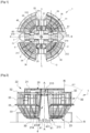
- the armature 20 is formed by two branches 21 extending respectively along two radial axes BB and CC perpendicular to one another.
- the two branches 21 extend between two lateral ends 210.
- the two branches 21 intersect at a point.
- the armature 20 has a cross-section in the shape of a cross which is visible to figure 1 , 3 , 5, 6 And 9 .
- This specific configuration of the frame 20 ensures the stiffening of the submersible body 2.
- each branch 21 comprises an upper flange 211 which extends between each side end 210 of the branch 21.
- the upper flange 211 defines the upper part 22 of the submersible body 2.
- the branch 21 comprises a side wall 212 extending from the upper rim 211 and towards a lower end 213.
- the lower end 213 of the side wall 212 defines the lower part 23 of the submersible body 2.
- Each side wall 212 is preferably perforated.
- the submersible body 2 is adapted to be suspended from a support such as a breeding table.
- the armature 20 comprises at least one through hole 24 which is arranged at the level of the point of intersection of the two branches 21.
- the axis along which the hole 24 is positioned corresponds to a suspension axis A-A of the breeding case 1.
- the suspension axis A is perpendicular to the plane formed by the two radial axes B-B, C-C of the branches 21.
- the orifice 24 is configured so that a rope can be threaded through the armature 20 of the permeable body 2.
- the branches 21 delimit a determined number of housings 3.
- the branches 21 compartmentalize the submersible body 2 into four separate housings 3 and spaced from each other.
- the submersible body 2 comprises four bivalve housings respectively arranged radially with respect to the suspension axis A-A and between two adjacent branches 21 of the frame 20.
- the frame 20 spaces each housing 3 by a determined distance. Spacing each bivalve also helps reduce the spread of germs, viruses and/or bacteria, such as the bacterium Vibrio spectacularus.
- each branch 21 has a cross section comprising two side walls 212 opposite each other and respectively connected to each side of the same upper rim 211. More specifically, the two side walls 212 extend from flared and symmetrical manner with respect to a median longitudinal plane of the branch 21. Preferably, the two side walls 212 have a greater spacing at the level of the lower end 213 with respect to the spacing at the upper end at the level of the upper rim 211.
- each branch 21 comprises a flared hollow structure which is open below and which defines a spanning space 214 which contributes to allowing interlocking by superposition with a branch 21 of another breeding case 1.
- the spanning space 214 is open in the lower part 23 of the frame 20 and delimited, on the one hand, laterally by the inner face of each side wall 212 of a branch 21, and on the other hand, superiorly by the upper rim 211.
- an upper rim 211 extends along its length between two lateral ends 210 over a distance of between 150 mm and 200 mm.
- an upper flange 211 extends in its width between each of its sides over a distance of between 15 mm and 25 mm.
- the spacing between the two lower ends 213 of each side wall 212 of the same branch 21 is between 30 mm and 40 mm.
- each housing 3 is equipped with a bottom 30 defining the lower part 23 of the submersible body 2.
- the bottom 30 extends from the lower end 213 of the adjacent side walls 212 belonging to two different branches 21.
- the housing 3 has a protective wall 31 which extends longitudinally from the bottom 30 of the housing 3 to an upper edge 32.
- the upper edge 32 is arranged at the level of the upper part 22 of the submersible body 2.
- the protective wall 31 comprises a front portion and two side portions which are integral with each branch 21 and which contributes to laterally delimiting the housing 3.
- the protective wall 31 comprises a lower portion 33 which extends longitudinally from the bottom 30 of the housing to a flange 34.
- the lower portion 33 is inclined with respect to a normal N which is parallel to suspension axis A-A.
- the angle of inclination ⁇ i of the lower portion 33 with respect to the normal N is between 15° and 30°, and preferably the angle of inclination ⁇ i with respect to the normal N is 20 °.
- the hinge of the bivalve or its dorsal part is positioned against the bottom 30 of the housing.
- the filtration membrane of the bivalve is oriented, by the inclination of the lower portion 33, towards the outside of the housing 4. This characteristic ensures better filtration and directs the growth of the bivalve according to the orientation of the protective wall. 31.
- the collar 34 equips the protective wall 31 and extends transversely between each of its side edges.
- the protective wall 31 also includes an upper portion 35 which extends longitudinally from the flange 34 to the upper edge 32.
- the protective wall 31 provides lateral protection for the housing 3. Indeed, it extends laterally from two adjacent lateral ends 210 of two different branches 21. This lateral protection makes it possible to laterally prohibit access to the housing 3 for predators such as sea bream.
- the housing 3 can also comprise a rear wall 310 which extends between two adjacent branches 21 inside the submersible body 2.
- the housing 3 is delimited, on the one hand, laterally by the wall of protection 31 and the rear wall 310, and on the other hand, below by the bottom 30.
- the protective wall 31 generates a housing 3 whose depth can vary between 70 mm and 100 mm.
- the depth of the housing 3 is defined by the distance between the bottom 30 of the housing 3 and the upper edge 32 of the protective wall 31.
- a housing 3 of this depth makes it possible to accommodate both bivalves at the spat stage and bivalves of adult sizes.
- the bottom 30 of the housing 3 and the protective wall 31 are formed by an openwork structure, of the lattice type.
- the mesh of the bottom 30 of the housing 3 and of the protective wall 31 has a mesh of determined dimensions.
- the lattice comprises a mesh of increasing dimensions from the bottom 30 of the housing 3 to the upper edge 32.
- the mesh of the lattice at the level of the bottom 30 of the housing may comprise dimensions between 2.5mm x 2.5mm and 6mm x 6mm.
- the mesh of the trellis in the upper part 35 can comprise dimensions comprised between 12 mm ⁇ 12 mm and 25 mm ⁇ 25 mm.
- the lattice mesh can be of any shape such as polygonal, parallelepiped, circular etc.
- the bottom mesh 30 may comprise a tighter mesh.
- Each dwelling can then accommodate small gravel or sand to promote the breeding of burrowing bivalves such as clams, clams, tellines, scallops, etc.
- the rear wall 310 may comprise a mesh which has the same properties as that of the protective wall 31.
- the characteristics of the housing 3, and in particular the trellis contribute, on the one hand, to facilitating the immersion and the emergence of the submersible body 2 from the breeding box 1, and on the other hand, to ensure a circulation of water and phytoplankton which guarantees good oxygenation of housing 3 and good supply of food to the bivalves contained in housing 3.
- the trellis enables the shellfish farmer to protect his production of bivalves without using a protective net.
- the inclined character of the lower portion 33 of the protective wall 31 makes it possible to reduce the volume of the housing 3 below the collar 34 which contributes to optimizing the interlocking by superposition of two breeding cases 1.
- breeding box 1 is configured to fit together by superposition below and above with other breeding boxes 1.
- the breeding box 1 is configured so that each bottom 30 of the housing 3 has a distance from the bottom 30 of the housing 3 of an upper and/or lower breeding box 1 by a distance of between 40 mm to 120mm. This makes it possible to obtain 8 to 15 breeding boxes 1 per meter.
- the breeding box 1 comprises locking means 4 sliding in translation.
- the interlocking means 4 make it possible to fit together two breeding cases 1 by superposition below or above.
- the interlocking means 4 also ensure reversible cohesion between the two nested breeding cases 1.
- the engagement means 4 comprise at least one female member 40 and at least one male member 41.
- the male member 41 is complementary to the female member 40.
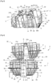
- the engagement means 4 of a first case of breeding 1 are configured to cooperate with the engagement means 4 of another breeding box 1 superimposed below and/or above with respect to the first breeding box 1 (illustrated in figures 4 to 8 ).
- the engagement means 4 have at least one female member 40 disposed in the upper part 22 of the submersible body 2.
- the female member 40 comprises at least one opening 400 located on a plane passing through the radial axis BB.
- the opening 400 is arranged at a first lateral end 210 of a branch 21.
- the opening 400 of the female member 40 communicates with a slide 401 which extends under the upper rim 211 along an axis parallel to the axis radial BB.
- the male member 41 is configured to slide in the slide 401 in order to engage in the female member 40.
- the male organ 41 is arranged in the lower part 23 of the submersible body 2.
- the respective positions of the male member 41 and of the female member 40 can be reversed.
- the female member 40 is placed in the lower part 23 of the submersible body 2.
- the male member 41 is then placed in the upper part 22 of the submersible body 2.
- the male member 41 comprises an offset segment 410 of the submersible body 2.
- the offset segment 410 makes it possible to offset an abutment 411 located at the free end of the offset segment 410.
- the abutment 411 is formed by a hook.
- the breeding case 1 comprises four female organs 40 and four male organs 41.
- the female organs 40 and the male organs 41 are distributed two by two on each branch 21 symmetrically with respect to the radial axes BB and CC .
- a male branch 21c comprises only male members 41 which are distributed two by two per pair on either side of the point of intersection between the branches 21, 21b, 21c.
- a male member 41 is disposed in the spanning space 214. More specifically, a male member 41 is disposed in the spanning space 214 at the level of the lower end 213 of a side wall 212.
- a pair of male members 41 is arranged on a plane P which is parallel to the female branch 21b.
- a male branch 21c comprises two pairs of male members 41 which are arranged at a determined distance from the point of intersection of the two branches 21, 21b, 21c.
- the two pairs of male members 41 are arranged at an equal distance from the point of intersection of the two branches 21, 21b, 21c.
- a female branch 21b comprises only female members 40 which are distributed two by two per pair on either side of the point of intersection between the branches 21, 21b, 21c.
- a female member 41 extends over the side wall 212 of the female branch 21b.
- a female branch 21b comprises two pairs of female members 40 which extend in pairs symmetrically with respect to the male branch 21c. Each pair of female members 40 extends on either side of the male branch 21c. The two female organs 40 which make up a couple, extend parallel to the female branch 21b.
- the engagement means 4 have a specific configuration which makes it possible to fit together two breeding boxes 1 by superposition when the radial axis B-B of a first breeding box 1 overlaps with the radial axis C-C of a second breeding box 1. This is due to the fact that the female organs 40 and the male organs 41 are distributed symmetrically over two distinct branches 21, 21b, 21c. Thus, to assemble two breeding boxes 1, it is necessary to rotate 90° along the suspension axis A-A a first breeding box 1 with respect to a second breeding box 1.
- a column 5 of breeding boxes 1 has an assembly of breeding boxes 1 in which each breeding box 1 is offset by 90° with respect to the breeding box 1 with which it is nested above and/or below.
- Each breeding box 1 of a column is respectively nested, along the suspension axis A-A, below and/or above with at least one other breeding box 1.
- the breeding case 1 comprises at least one displacement slide 6 which is provided in the submersible body 2.
- the submersible body 2 comprises four displacement slides 6. Each displacement slide 6 communicates respectively with the slide engagement 401 of the female member 40 of the engagement means 4.
- Each displacement slide 6 extends along an axis parallel to the suspension axis A-A.
- the male member 41 when the male member 41 is engaged in the displacement slide, it can slide in the displacement slide 6 in a direction parallel to the suspension axis A-A.
- a first pair of male organs 41 of the upper breeding case 1 is engaged, by sliding according to a translational movement in a first direction, in a first pair of female organs 40 of the upper breeding case. rearing 1 lower.
- the first pair of male organs 41 of the upper breeding box 1 is brought into abutment against the male branch 21c of the lower breeding box 1 in order to allow the engagement of the second pair of male organs 41 of the upper breeding box 1 in the second pair of female organs 40 of the lower breeding box 1.
- This is followed by a second translation movement in a second direction opposite to the first direction of translation. THE second translational movement brings the two pairs of male members 41 of the upper breeding box 1 into the engaged position.
- each male member 41 of the upper breeding case 1 is engaged in a displacement slide 6.
- two breeding cases 1 are movable in translation relative to each other along the suspension axis AA through each displacement slide 6.
- the displacement slides 6 are arranged two by two on a plane Q which is parallel to the male branch 21c.
- the displacement slides 6 and the male members 41 are arranged at an identical distance from the point of intersection of the two branches 21, 21b, 21c.
- each male member 41 of the upper breeding box is located at a lower end of a sliding slide 6 of the lower breeding box.
- the upper breeding box 1 then rests on the lower breeding box 1 (illustrated in figure 6 ).
- each male member 41 of the upper breeding case 1 abuts against the upper rim 211 of a female branch 21b of the lower breeding case 1.
- the two breeding cases 1 are kept at a distance from each other while remaining engaged (illustrated in figure 5 ).
- this mobility of two breeding boxes 1 interlocked with each other can be transposed to a column 5 of breeding boxes 1, the column being able to pass from a compact state to a deployed state under the effect of an actuator.
- the actuator can be a rope threaded into the orifice 24 of each breeding box 1 which makes up the column 5. Raising this rope makes it possible to pass the column 5 from a deployed state to a compact state, vice versa giving slack to the rope makes it possible to pass from the compact state to the deployed state.
- the compact state can be useful for transporting a column of rearing boxes 1 from a land site where the rearing boxes 1 of column 5 can be loaded with bivalves to a rearing table located in an expanse of 'water.
- the compact state makes it possible to protect bivalves in the spat state and/or to maintain them in each housing during the launching of the column 5 for rearing bivalves. This is also valid for higher caliber bivalves.
- the deployed state can be used when rearing bivalves in suspension, in fact the spacing between the rearing boxes 1 promotes the growth of the bivalves.
- the expanded state can also be used before cultivation when loading bivalves from the column 5 and when unloading column 5 when the bivalves reach maturity for consumption.
- a breeding box 1 of the column 5 contributes to restricting access to the housings 3 of the breeding box 1 which is nested below. In this sense, the breeding box at the top of column 5 may not be loaded with bivalves in order to avoid losses caused by predators.
- the submersible body 2 comprises at least one polarizer 25.
- the polarizer 25 is placed on a male branch 21c in the plane P common to the two male members 41.
- the submersible body 2 comprises four polarizers 25.
- Each polarizer 25 is formed by a slide which does not include a stop and therefore does not allow two cases of rearing 1 by superposition.
- the tilting is obtained by lifting a part of the upper breeding box 1 located on one side of its male branch 21c. 21b of the lower box 1, while the other two male organs 41 of the upper breeding box tilt within the slide rail 6.
- the movement slide 6 comprises a rocker stop 60 arranged at the level of the upper edge 211.
- the rocker stop 60 is arranged in the extension of the movement slide 6.
- the rocker stop 60 is arranged on the same axis as the displacement slide 6.
- the rocker stop 60 is formed by a slot formed in the upper rim 211. The slot extends longitudinally along the radial axis B-B.
- the hook of the male member 41 engages between the slot of the rocking stop 60 and the edge of the upper rim 211, generating a rocking movement of the upper breeding box.
- the tilting stop 60 allows a tilting while preventing a dislocation of the upper breeding case 1.
- the tilting makes it possible to load a column 5 assembled with a determined number of breeding boxes 1 with bivalves before launching. Conversely, failover allows to unload mature bivalves after culture in an aquaculture environment. The loading and unloading operations of the breeding cases 1 of a column are facilitated by this tilting phenomenon. Furthermore, as two successive breeding boxes 1 are nested according to a radial offset of 90°, the tilting of two successive breeding boxes of the same column also takes place according to a radial offset of 90°.
- the submersible body 2 comprises at least two arms 7 which extend externally to the submersible body 2 on the radial axis BB or on the radial axis CC, each arm 7 being connected to the frame 20.
- each arm is connected to the frame 20 through the protective walls 31 of the housings 3 located on either side of the radial axis BB and / or the radial axis CC.
- Each arm 7 is arranged in the same plane R as the male members 41.
- the plane R extends under the submersible body 2 of the breeding box 1.
- the plane R is parallel to the plane formed by the radial axes BB and CC.
- the submersible body 2 can also comprise four arms 7 located on the two radial axes BB and CC (illustrated in figure 7 ).
- an arm 7 comprises a free end 70 equipped with a hook and at least one offset segment 71 of the structure of the submersible body 2.
- the hook is oriented in the direction of the suspension axis A-A.
- the hook has the same orientation as the male members 41 which are located on the same side of the radial axis C-C.
- the arms 7 participate in maintaining the cohesion of a column 5 comprising a determined number of breeding boxes 1. Indeed, the arms 7 extend out of the structure and make it possible to maintain the breeding box 1 lower in the axis of the upper breeding case 1. This can be useful in an aquaculture site subject to periodic swells.
- the arms 7 also contribute to preventing the dislocation of two successive breeding boxes in a tipping situation (illustrated in figure 8 ). This situation can occur during the loading of the bivalves in each housing 3 of a column 5 of breeding cases 1. In this situation out of the water, the column 5 is suspended in order to fill it with bivalves, the arms 7 contribute by their position in the plane R and by their orientation to maintain the column 5 straight.
- the breeding box 1 may comprise means 8 for constraining the growth of at least one bivalve.
- the stressing means 8 make it possible to grow the bivalve according to a determined shape.
- the stressing means 8 can be formed by a rope 80 which is arranged so as to hinder the growth of the bivalve along an axis.
- a stress applied to the frontal part of the bivalve can cause the bivalve 3 to form a heart-shaped shell.
- the positioning of the string 80 is chosen at through drilling 36 which are provided on the flange 34 of the protective wall 31. Due to the perforated nature of the submersible body 2, a rope 80 can run from one housing 3 to another to stress the bivalves contained respectively in each apartment 3.
- the stressing means 8 can also be formed by a claw, a rod.
- a column 5 of breeding cases 1 requires a means of attachment to this table.
- the upper breeding box 1 of a column 5 can be connected to a table through a suspension cord 9 which has four points of attachment to the upper breeding box 1.
- the suspension cord 9 is divided into four so as to be threaded under each branch 21. The attachment at four points makes it possible to maintain the column 5 in suspension in a balanced manner.
- the attachment points may correspond to orifices 215 which are provided at the level of the lateral ends 210 of at least one branch 21, 21b, 21c. Each orifice 215 extends along the radial axis of the branch 21 in which it is arranged (illustrated in figure 2 , 3 And 5 ).
- the suspension cord 9 can also pass through two opposite arms 7, always with the aim of stabilizing the structure in suspension.
- the invention also relates to a method for rearing bivalves in suspension comprising at least one bivalve rearing column 5 comprising a determined number of rearing boxes 1.
- the breeding method comprises a step of loading the housings 3 of each breeding case 1 of a column 5.
- a single bivalve is inserted per housing 3.
- the bivalves are inserted in the spat state whether they are large calibers (T20) or small calibers (T6, T8).
- a column 1 of fifty breeding boxes has a height of less than 1.5 meters. This low height makes it possible to easily transport the column 5 in the compact state from a loading site to a breeding table.
- a column 5 Before launching, a column 5 is placed in its compact state in order to transport each column 5 to the rearing site.
- the transition from the deployed state to the compact state is managed through the rope which extends along the suspension axis A-A of each breeding box 1.
- the rearing method comprises a step of immersing at least one rearing column 5 in a compact state.
- each housing 3 of each breeding box 1 comprising at least one bivalve.
- the method may include a pre-culture step during which the rearing column 5 is kept immersed in its compact state for a determined period.
- This duration essentially depends on the size of the spat that have been loaded into the housings 3. This step makes it possible to preserve and protect the spat so that they absorb water and are maintained at the bottom 30 of their housing 3. Indeed, when they are loaded into each housing 3, the spat are not sufficiently loaded with water to remain at the bottom 30 of each housing 3 during immersion.
- the duration of the pre-culture stage can vary from one minute or less for large size spat (T20) to 7 to 30 days for small size spat (T6, T8). If the immersion takes place in the presence of a large swell, the duration of the pre-culture step is preferably extended until the swell subsides.
- the breeding method comprises a step of deploying the column 5 of breeding boxes 1. This step consists in releasing the upper end of the rope which extends along the suspension axis A-A, the boxes of breeding 1 then passing, under the effect of gravity, from a compact state to a deployed state.
- the step of deploying the column 5 is preferably carried out during the growth period of the bivalves. That is to say in the spring and/or in the fall.
- the growth period is essentially due to the presence of plankton in the aquaculture environment.
- the culture method includes a bivalve culture step, during which a culture column 5 is kept submerged in an extended state.
- the deployed state ensures optimum growth of the bivalves 2.
- the rearing stage can be between 6 and 18 months and preferably the development stage can be between 10 and 14 months.
- the rearing process may include one or more periods of exposure to simulate ocean marshes.
- the exposure technique is well known to operators shellfish, it strengthens the bivalves by generating periods of stress which are followed by strong growth spurts.
- the rearing method comprises an operation of emersion of the set of rearing boxes 1 while the bivalves 2 have reached their adult size. Emersion is achieved by raising the suspension rope 9.
- the method also includes an operation for extracting the bivalves.
- This step consists in separating the bivalves from each rearing box 1.
- This operation can be carried out directly during emergence. In general, emersion is carried out using a lifting mat.
- the tilting movement of each rearing box 1 of a column 5 allows extraction of adult-sized bivalves during emergence.
- the method may also include steps for treating the bivalves according to the marketing criteria in force.
- the bivalves can be subjected to a purification and storage bath before being marketed.
Landscapes
- Life Sciences & Earth Sciences (AREA)
- Environmental Sciences (AREA)
- Marine Sciences & Fisheries (AREA)
- Zoology (AREA)
- Animal Husbandry (AREA)
- Biodiversity & Conservation Biology (AREA)
- Farming Of Fish And Shellfish (AREA)
Claims (11)
- Aufzuchtkasten (1) für Muscheln, umfassend einen Tauchkörper (2), der mindestens eine Öffnung (24) aufweist, durch die ein Seil eingefädelt werden kann, wobei der Aufzuchtkasten (1) mindestens ein im Tauchkörper (2) angeordnetes Gehäuse (3) umfasst und geeignet ist, mindestens eine Muschel aufzunehmen und zu schützen, wobei der Tauchkörper (2) einen Rahmen (20) besitzt, der sich von einem oberen Rand (211) erstreckt, der den oberen Teil (22) des Tauchkörpers (2) und in Richtung eines unteren Endes (213) mindestens einer Seitenwand (212) definiert, wobei das untere Ende (213) der Seitenwand (212) den unteren Teil (23) des Tauchkörpers (2) definiert, wobei der Rahmen (20) aus zwei Schenkeln (21) ausgebildet ist, die sich jeweils entlang zwei radialer Achsen (B-B, C-C) senkrecht zueinander erstrecken, wobei sich die beiden Schenkel (21) an einem Punkt schneiden, der einer Öffnung (24) entspricht, durch die eine Aufhängungsachse (A-A) verläuft, die senkrecht zu der durch die beiden Radialachsen (B-B, C-C) der Schenkel (21) gebildeten Ebene ist, wobei die Schenkel (21) eine bestimmte Anzahl von Gehäusen (3) begrenzen, wobei jedes Gehäuse (3) einerseits mit einem Boden (30), der den unteren Teil (23) des Tauchkörpers (2) definiert, und andererseits mit einer Schutzwand (31) ausgestattet ist, die sich vom Boden (30) des Gehäuses (3) zu einem oberen Rand (32) erstreckt, die auf Höhe des oberen Teils (22) des Tauchkörpers (2) angeordnet ist, wobei der Kasten dadurch gekennzeichnet ist, dass der Aufzuchtkasten (1) mindestens eine Verschiebungsschiene (6) und beim Gleiten sich bewegende Eingriffsmittel umfasst (4), die in der Eingriffsposition mit der Verschiebungsschiene (6) kommunizieren, wobei die Eingriffsmittel (4) ermöglichen, zwei Aufzuchtkästen (1) durch Übereinanderlegen zusammenzufügen, während die Verschiebungsschiene (6) dazu beiträgt, einerseits die zwei übereinandergelegten Aufzuchtkästen (1) translatorisch entlang der Aufhängungsachse (A-A) beweglich zu machen und andererseits eine Kippbewegung des oberen Aufzuchtkastens (1) relativ zum unteren Aufzuchtkasten (1) zu ermöglichen.
- Aufzuchtkasten (1) für Muscheln nach Anspruch 1, dadurch gekennzeichnet, dass die Eingriffsmittel (4) besitzen:- mindestens ein weibliches Element (40), das im oberen Teil (22) des Tauchkörpers (2) angeordnet ist, wobei das mindestens eine weibliche Element (40) mindestens eine Öffnung (400) umfasst, die in einer Ebene liegt, die durch eine erste Radialachse (B-B) verläuft, wobei die Öffnung (400) mit einer Eingriffsschiene (401) parallel zu dieser Radialachse (B-B) kommuniziert,- mindestens ein männliches Element (41), das im unteren Teil (23) des Tauchkörpers (2) angeordnet ist, wobei das mindestens eine männliche Element (41) ein versetztes Segment (410) des Tauchkörpers (2) und einen Anschlag (411) umfasst, der am freien Ende (412) des versetzten Segments (410) angeordnet ist, und- das mindestens eine männliche Element (41) komplementär zu dem mindestens einen weiblichen Element (40) konfiguriert ist.
- Aufzuchtkasten (1) für Muscheln nach Anspruch 1, dadurch gekennzeichnet, dass die Eingriffsmittel (4) besitzen:- mindestens ein weibliches Element (40), das im unteren Teil (23) des Tauchkörpers (2) angeordnet ist, wobei das mindestens eine weibliche Element (40) mindestens eine Öffnung (400) umfasst, die in einer Ebene liegt, die durch eine erste Radialachse (B-B) verläuft, wobei die Öffnung mit einer Eingriffsschiene parallel zu dieser Radialachse (B-B) kommuniziert,- mindestens ein männliches Element (41), das im oberen Teil (22) des Tauchkörpers (2) angeordnet ist, wobei das mindestens eine männliche Element (41) ein versetztes Segment (410) des Tauchkörpers (2) und einen Anschlag (411) umfasst, der am freien Ende (412) des versetzten Segments (410) angeordnet ist, und- das mindestens eine männliche Element (41) komplementär zu dem mindestens einen weiblichen Element (40) konfiguriert ist.
- Aufzuchtkasten (1) für Muscheln nach einem der Ansprüche 1 bis 3, dadurch gekennzeichnet, dass die Verschiebungsschiene (6) einen auf Höhe der Oberkante (211) angeordneten Kippanschlag (60) aufweist.
- Aufzuchtkasten (1) für Muscheln nach einem der Ansprüche 1 bis 4, dadurch gekennzeichnet, dass er vier Gehäuse (3) für Muscheln umfasst, die jeweils radial relativ zur Aufhängungsachse (A-A) und zwischen zwei Schenkeln (21) des Rahmens (20) angeordnet sind.
- Aufzuchtkasten (1) für Muscheln nach einem der Ansprüche 1 bis 5, dadurch gekennzeichnet, dass jeder Schenkel (21) einen quer verlaufenden Abschnitt vorweist, der zwei einander gegenüberliegende Seitenwände (212) umfasst, die jeweils an jedem Ende mit einer Oberkante (211) verbunden sind, die den oberen Teil (22) des Tauchkörpers (2) definiert, wobei die beiden Seitenwände (212) sich konisch erweiternd und symmetrisch in Bezug auf eine mittlere Längsebene des Schenkels (21) erstrecken.
- Aufzuchtkasten (1) für Muscheln nach einem der Ansprüche 1 bis 6, dadurch gekennzeichnet, dass die Schutzwand (31) ein Gitter besitzt, dessen Maschenweite vom Boden (30) des Gehäuses (3) bis zum oberen Rand (32) hin zunehmende Abmessungen vorweist.
- Aufzuchtkasten (1) für Muscheln nach einem der Ansprüche 1 bis 7, dadurch gekennzeichnet, dass er mindestens zwei Arme (7) umfasst, die sich außerhalb des Tauchkörpers (2) auf einer ersten Radialachse (B-B) und/oder auf der zweiten Radialachse (C-C) erstrecken, wobei jeder Arm (7) mit dem Rahmen (20) verbunden ist.
- Aufzuchtbox (1) für Muscheln nach einem der Ansprüche 1 bis 8, dadurch gekennzeichnet, dass der Tauchkörper (2) Begrenzungsmittel (8) für das Wachstum mindestens einer Muschel umfasst, die sie in einer bestimmten Weise wachsen lassen.
- Aufhängungssäule (5) zur Aufzucht von Muscheln, aufweisend eine bestimmte Anzahl von Aufzuchtkästen (1), die nach einem der Ansprüche 1 bis 9 definiert sind, dadurch gekennzeichnet, dass jeder Aufzuchtkasten (1) gemäß der Aufhängungsachse (A-A) jeweils durch inneres und/oder äußeres Übereinanderlegen verschachtelt ist, wobei die zwei verschachtelten Aufzuchtkästen (1) einerseits beweglich zueinander zwischen einem kompakten Zustand, in dem die Aufzuchtkästen (1) aufeinander aufliegen, und einem ausgespannten Zustand, in dem die Aufzuchtkästen (1) im Eingriff zueinander auf Abstand gehalten werden, konfiguriert sind, und andererseits, um eine Verkippung um eine Radialachse (B-B, C-C) des oberen Aufzuchtkastens (1) relativ zum unteren Aufzuchtkasten (1) zu ermöglichen.
- Aufhängungsverfahren zur Aufzucht von Muscheln, umfassend mindestens eine Muschelaufzuchtsäule (5) nach Anspruch 10, wobei das Aufzuchtverfahren umfasst:- einen Schritt des Eintauchens mindestens einer Aufzuchtsäule (5) in einem kompakten Zustand, wobei jedes Gehäuse (3) jedes Aufzuchtkastens (1) mindestens eine Muschel aufweist; und- einen Schritt der Muschelaufzucht, bei dem eine Aufzuchtsäule (5) in einem ausgespannten Zustand eingetaucht gehalten wird.
Applications Claiming Priority (2)
| Application Number | Priority Date | Filing Date | Title |
|---|---|---|---|
| FR1907292A FR3098087B1 (fr) | 2019-07-01 | 2019-07-01 | Écrin, colonne et procédé d’élevage de bivalves |
| PCT/EP2020/068535 WO2021001430A1 (fr) | 2019-07-01 | 2020-07-01 | Écrin, colonne et procédé d'élevage de bivalves |
Publications (2)
| Publication Number | Publication Date |
|---|---|
| EP3993620A1 EP3993620A1 (de) | 2022-05-11 |
| EP3993620B1 true EP3993620B1 (de) | 2023-09-06 |
Family
ID=68806875
Family Applications (1)
| Application Number | Title | Priority Date | Filing Date |
|---|---|---|---|
| EP20734962.2A Active EP3993620B1 (de) | 2019-07-01 | 2020-07-01 | Gehäuse, säule und verfahren zur züchtung von muscheln |
Country Status (9)
| Country | Link |
|---|---|
| US (1) | US12232486B2 (de) |
| EP (1) | EP3993620B1 (de) |
| JP (1) | JP2023501034A (de) |
| KR (1) | KR20220024223A (de) |
| CN (1) | CN114080154A (de) |
| AU (1) | AU2020299994B2 (de) |
| CA (1) | CA3145645A1 (de) |
| FR (1) | FR3098087B1 (de) |
| WO (1) | WO2021001430A1 (de) |
Family Cites Families (12)
| Publication number | Priority date | Publication date | Assignee | Title |
|---|---|---|---|---|
| FR2112566A5 (de) * | 1970-08-12 | 1972-06-23 | Balaunbrenner Lazare | |
| US3870019A (en) * | 1971-02-10 | 1975-03-11 | Douglas Mcnicol | Oyster culture basket |
| US3702599A (en) * | 1971-05-27 | 1972-11-14 | Vanguard Industries | Shellfish growout tray |
| US5515813A (en) | 1994-05-09 | 1996-05-14 | Wilkerson; Douglas D. | Aquatic cultivator |
| JP2005253424A (ja) * | 2004-03-15 | 2005-09-22 | Daikure Co Ltd | 牡蠣養殖用の干出装置 |
| ES1061127Y (es) | 2005-10-03 | 2006-04-16 | Inst Espanol De Oceanografia | Jaula para el cultivo acuatico de moluscos. |
| WO2009140689A2 (en) * | 2008-05-16 | 2009-11-19 | Atmocean, Inc. | Method and apparatus for increasing upper-level fish populations |
| CN101491207B (zh) * | 2009-02-19 | 2011-06-29 | 浙江海洋学院 | 一体化大型筏式养殖装置 |
| JP5029854B2 (ja) * | 2010-07-15 | 2012-09-19 | 義裕 藤芳 | 二枚貝等の底棲生物の養殖装置 |
| CN102823524B (zh) * | 2012-08-16 | 2014-03-12 | 中国水产科学研究院东海水产研究所 | 一种外附加牵引式离岸海洋网箱升降控制装置及方法 |
| FR3032860B1 (fr) | 2015-02-20 | 2017-03-24 | Cambon Et Fils | Dispositif d'elevage de bivalves |
| FR3062026A1 (fr) * | 2017-01-24 | 2018-07-27 | Philippe Giboulot | Dispositif de fixation de coquillages a une corde sans collage, de limite de croissance et de protection contre les predateurs |
-
2019
- 2019-07-01 FR FR1907292A patent/FR3098087B1/fr not_active Expired - Fee Related
-
2020
- 2020-07-01 EP EP20734962.2A patent/EP3993620B1/de active Active
- 2020-07-01 US US17/624,331 patent/US12232486B2/en active Active
- 2020-07-01 WO PCT/EP2020/068535 patent/WO2021001430A1/fr not_active Ceased
- 2020-07-01 AU AU2020299994A patent/AU2020299994B2/en active Active
- 2020-07-01 CN CN202080048712.4A patent/CN114080154A/zh active Pending
- 2020-07-01 JP JP2022500523A patent/JP2023501034A/ja active Pending
- 2020-07-01 KR KR1020217043436A patent/KR20220024223A/ko not_active Withdrawn
- 2020-07-01 CA CA3145645A patent/CA3145645A1/fr active Pending
Also Published As
| Publication number | Publication date |
|---|---|
| AU2020299994B2 (en) | 2026-04-09 |
| WO2021001430A1 (fr) | 2021-01-07 |
| JP2023501034A (ja) | 2023-01-18 |
| FR3098087B1 (fr) | 2022-12-30 |
| US20220272950A1 (en) | 2022-09-01 |
| US12232486B2 (en) | 2025-02-25 |
| AU2020299994A1 (en) | 2022-02-03 |
| KR20220024223A (ko) | 2022-03-03 |
| CN114080154A (zh) | 2022-02-22 |
| FR3098087A1 (fr) | 2021-01-08 |
| EP3993620A1 (de) | 2022-05-11 |
| CA3145645A1 (fr) | 2021-01-07 |
Similar Documents
| Publication | Publication Date | Title |
|---|---|---|
| EP3700332B1 (de) | Vorrichtung zur aufzucht von aquakulturtieren auf dem meer | |
| FR2597716A1 (fr) | Une methode et un dispositif de culture et/ou d'elevage des mollusques et crustaces tels que les benitiers. | |
| WO2018019884A1 (fr) | Dispositif d'élevage en mer d'animaux d'aquaculture | |
| FR3003128A1 (fr) | Portique pour l'elevage d'huitres | |
| FR3054952B1 (fr) | Dispositif d'elevage en mer d'animaux d'aquaculture | |
| JP4489706B2 (ja) | 藻場増殖礁 | |
| EP3993620A1 (de) | Gehäuse, säule und verfahren zur züchtung von muscheln | |
| JP3598514B2 (ja) | 餌料培養礁を備えた人工魚礁 | |
| JP2005253424A (ja) | 牡蠣養殖用の干出装置 | |
| EP3700331B1 (de) | Vorrichtung zur aufzucht von aquakulturtieren auf dem meer | |
| WO2013054183A1 (fr) | Module d'habitation pour la protection de post-larves notamment dans des infrastructures portuaires | |
| FR2841741A1 (fr) | Dispositif pour l'elevage de mollusques filtreurs en suspension en pleine eau | |
| US20260123607A1 (en) | Aquaculture basket | |
| WO2020064144A1 (fr) | Installation d'aquaculture comprenant une structure flottante contenant au moins une cage pour l'elevage de poissons | |
| EP4512242A1 (de) | Vorrichtung zur schalentierzucht und verfahren dafür | |
| FR3145258A1 (fr) | Contenants a coquillages et supports de suspension correspondants | |
| FR3006554A1 (fr) | Ensemble modulaire pour alevins et autres organismes aquatiques | |
| WO2002087318A1 (fr) | Habitat modulaire pour organismes marins | |
| Le Anh et al. | 2.4 Lobster seed fishing, handling and transport in Vietnam | |
| FR2733389A1 (fr) | Procede d'elevage d'huitres, notamment d'huitres perlieres pour la production de perles de culture et installation pour la mise en oeuvre de ce procede |
Legal Events
| Date | Code | Title | Description |
|---|---|---|---|
| STAA | Information on the status of an ep patent application or granted ep patent |
Free format text: STATUS: UNKNOWN |
|
| STAA | Information on the status of an ep patent application or granted ep patent |
Free format text: STATUS: THE INTERNATIONAL PUBLICATION HAS BEEN MADE |
|
| PUAI | Public reference made under article 153(3) epc to a published international application that has entered the european phase |
Free format text: ORIGINAL CODE: 0009012 |
|
| STAA | Information on the status of an ep patent application or granted ep patent |
Free format text: STATUS: REQUEST FOR EXAMINATION WAS MADE |
|
| 17P | Request for examination filed |
Effective date: 20220127 |
|
| AK | Designated contracting states |
Kind code of ref document: A1 Designated state(s): AL AT BE BG CH CY CZ DE DK EE ES FI FR GB GR HR HU IE IS IT LI LT LU LV MC MK MT NL NO PL PT RO RS SE SI SK SM TR |
|
| DAV | Request for validation of the european patent (deleted) | ||
| DAX | Request for extension of the european patent (deleted) | ||
| GRAP | Despatch of communication of intention to grant a patent |
Free format text: ORIGINAL CODE: EPIDOSNIGR1 |
|
| STAA | Information on the status of an ep patent application or granted ep patent |
Free format text: STATUS: GRANT OF PATENT IS INTENDED |
|
| INTG | Intention to grant announced |
Effective date: 20230328 |
|
| GRAS | Grant fee paid |
Free format text: ORIGINAL CODE: EPIDOSNIGR3 |
|
| GRAA | (expected) grant |
Free format text: ORIGINAL CODE: 0009210 |
|
| STAA | Information on the status of an ep patent application or granted ep patent |
Free format text: STATUS: THE PATENT HAS BEEN GRANTED |
|
| AK | Designated contracting states |
Kind code of ref document: B1 Designated state(s): AL AT BE BG CH CY CZ DE DK EE ES FI FR GB GR HR HU IE IS IT LI LT LU LV MC MK MT NL NO PL PT RO RS SE SI SK SM TR |
|
| REG | Reference to a national code |
Ref country code: GB Ref legal event code: FG4D Free format text: NOT ENGLISH |
|
| REG | Reference to a national code |
Ref country code: CH Ref legal event code: EP |
|
| REG | Reference to a national code |
Ref country code: IE Ref legal event code: FG4D Free format text: LANGUAGE OF EP DOCUMENT: FRENCH |
|
| REG | Reference to a national code |
Ref country code: DE Ref legal event code: R096 Ref document number: 602020017248 Country of ref document: DE |
|
| REG | Reference to a national code |
Ref country code: LT Ref legal event code: MG9D |
|
| REG | Reference to a national code |
Ref country code: NL Ref legal event code: MP Effective date: 20230906 |
|
| PG25 | Lapsed in a contracting state [announced via postgrant information from national office to epo] |
Ref country code: GR Free format text: LAPSE BECAUSE OF FAILURE TO SUBMIT A TRANSLATION OF THE DESCRIPTION OR TO PAY THE FEE WITHIN THE PRESCRIBED TIME-LIMIT Effective date: 20231207 |
|
| PG25 | Lapsed in a contracting state [announced via postgrant information from national office to epo] |
Ref country code: SE Free format text: LAPSE BECAUSE OF FAILURE TO SUBMIT A TRANSLATION OF THE DESCRIPTION OR TO PAY THE FEE WITHIN THE PRESCRIBED TIME-LIMIT Effective date: 20230906 Ref country code: RS Free format text: LAPSE BECAUSE OF FAILURE TO SUBMIT A TRANSLATION OF THE DESCRIPTION OR TO PAY THE FEE WITHIN THE PRESCRIBED TIME-LIMIT Effective date: 20230906 Ref country code: NO Free format text: LAPSE BECAUSE OF FAILURE TO SUBMIT A TRANSLATION OF THE DESCRIPTION OR TO PAY THE FEE WITHIN THE PRESCRIBED TIME-LIMIT Effective date: 20231206 Ref country code: LV Free format text: LAPSE BECAUSE OF FAILURE TO SUBMIT A TRANSLATION OF THE DESCRIPTION OR TO PAY THE FEE WITHIN THE PRESCRIBED TIME-LIMIT Effective date: 20230906 Ref country code: LT Free format text: LAPSE BECAUSE OF FAILURE TO SUBMIT A TRANSLATION OF THE DESCRIPTION OR TO PAY THE FEE WITHIN THE PRESCRIBED TIME-LIMIT Effective date: 20230906 Ref country code: HR Free format text: LAPSE BECAUSE OF FAILURE TO SUBMIT A TRANSLATION OF THE DESCRIPTION OR TO PAY THE FEE WITHIN THE PRESCRIBED TIME-LIMIT Effective date: 20230906 Ref country code: GR Free format text: LAPSE BECAUSE OF FAILURE TO SUBMIT A TRANSLATION OF THE DESCRIPTION OR TO PAY THE FEE WITHIN THE PRESCRIBED TIME-LIMIT Effective date: 20231207 Ref country code: FI Free format text: LAPSE BECAUSE OF FAILURE TO SUBMIT A TRANSLATION OF THE DESCRIPTION OR TO PAY THE FEE WITHIN THE PRESCRIBED TIME-LIMIT Effective date: 20230906 |
|
| REG | Reference to a national code |
Ref country code: AT Ref legal event code: MK05 Ref document number: 1607222 Country of ref document: AT Kind code of ref document: T Effective date: 20230906 |
|
| PG25 | Lapsed in a contracting state [announced via postgrant information from national office to epo] |
Ref country code: NL Free format text: LAPSE BECAUSE OF FAILURE TO SUBMIT A TRANSLATION OF THE DESCRIPTION OR TO PAY THE FEE WITHIN THE PRESCRIBED TIME-LIMIT Effective date: 20230906 |
|
| PG25 | Lapsed in a contracting state [announced via postgrant information from national office to epo] |
Ref country code: IS Free format text: LAPSE BECAUSE OF FAILURE TO SUBMIT A TRANSLATION OF THE DESCRIPTION OR TO PAY THE FEE WITHIN THE PRESCRIBED TIME-LIMIT Effective date: 20240106 |
|
| PG25 | Lapsed in a contracting state [announced via postgrant information from national office to epo] |
Ref country code: AT Free format text: LAPSE BECAUSE OF FAILURE TO SUBMIT A TRANSLATION OF THE DESCRIPTION OR TO PAY THE FEE WITHIN THE PRESCRIBED TIME-LIMIT Effective date: 20230906 |
|
| PG25 | Lapsed in a contracting state [announced via postgrant information from national office to epo] |
Ref country code: ES Free format text: LAPSE BECAUSE OF FAILURE TO SUBMIT A TRANSLATION OF THE DESCRIPTION OR TO PAY THE FEE WITHIN THE PRESCRIBED TIME-LIMIT Effective date: 20230906 |
|
| PG25 | Lapsed in a contracting state [announced via postgrant information from national office to epo] |
Ref country code: SM Free format text: LAPSE BECAUSE OF FAILURE TO SUBMIT A TRANSLATION OF THE DESCRIPTION OR TO PAY THE FEE WITHIN THE PRESCRIBED TIME-LIMIT Effective date: 20230906 Ref country code: RO Free format text: LAPSE BECAUSE OF FAILURE TO SUBMIT A TRANSLATION OF THE DESCRIPTION OR TO PAY THE FEE WITHIN THE PRESCRIBED TIME-LIMIT Effective date: 20230906 Ref country code: IS Free format text: LAPSE BECAUSE OF FAILURE TO SUBMIT A TRANSLATION OF THE DESCRIPTION OR TO PAY THE FEE WITHIN THE PRESCRIBED TIME-LIMIT Effective date: 20240106 Ref country code: ES Free format text: LAPSE BECAUSE OF FAILURE TO SUBMIT A TRANSLATION OF THE DESCRIPTION OR TO PAY THE FEE WITHIN THE PRESCRIBED TIME-LIMIT Effective date: 20230906 Ref country code: EE Free format text: LAPSE BECAUSE OF FAILURE TO SUBMIT A TRANSLATION OF THE DESCRIPTION OR TO PAY THE FEE WITHIN THE PRESCRIBED TIME-LIMIT Effective date: 20230906 Ref country code: CZ Free format text: LAPSE BECAUSE OF FAILURE TO SUBMIT A TRANSLATION OF THE DESCRIPTION OR TO PAY THE FEE WITHIN THE PRESCRIBED TIME-LIMIT Effective date: 20230906 Ref country code: AT Free format text: LAPSE BECAUSE OF FAILURE TO SUBMIT A TRANSLATION OF THE DESCRIPTION OR TO PAY THE FEE WITHIN THE PRESCRIBED TIME-LIMIT Effective date: 20230906 Ref country code: PT Free format text: LAPSE BECAUSE OF FAILURE TO SUBMIT A TRANSLATION OF THE DESCRIPTION OR TO PAY THE FEE WITHIN THE PRESCRIBED TIME-LIMIT Effective date: 20240108 Ref country code: SK Free format text: LAPSE BECAUSE OF FAILURE TO SUBMIT A TRANSLATION OF THE DESCRIPTION OR TO PAY THE FEE WITHIN THE PRESCRIBED TIME-LIMIT Effective date: 20230906 |
|
| PG25 | Lapsed in a contracting state [announced via postgrant information from national office to epo] |
Ref country code: PL Free format text: LAPSE BECAUSE OF FAILURE TO SUBMIT A TRANSLATION OF THE DESCRIPTION OR TO PAY THE FEE WITHIN THE PRESCRIBED TIME-LIMIT Effective date: 20230906 Ref country code: IT Free format text: LAPSE BECAUSE OF FAILURE TO SUBMIT A TRANSLATION OF THE DESCRIPTION OR TO PAY THE FEE WITHIN THE PRESCRIBED TIME-LIMIT Effective date: 20230906 |
|
| REG | Reference to a national code |
Ref country code: DE Ref legal event code: R097 Ref document number: 602020017248 Country of ref document: DE |
|
| PG25 | Lapsed in a contracting state [announced via postgrant information from national office to epo] |
Ref country code: DK Free format text: LAPSE BECAUSE OF FAILURE TO SUBMIT A TRANSLATION OF THE DESCRIPTION OR TO PAY THE FEE WITHIN THE PRESCRIBED TIME-LIMIT Effective date: 20230906 |
|
| PLBE | No opposition filed within time limit |
Free format text: ORIGINAL CODE: 0009261 |
|
| STAA | Information on the status of an ep patent application or granted ep patent |
Free format text: STATUS: NO OPPOSITION FILED WITHIN TIME LIMIT |
|
| PG25 | Lapsed in a contracting state [announced via postgrant information from national office to epo] |
Ref country code: DK Free format text: LAPSE BECAUSE OF FAILURE TO SUBMIT A TRANSLATION OF THE DESCRIPTION OR TO PAY THE FEE WITHIN THE PRESCRIBED TIME-LIMIT Effective date: 20230906 Ref country code: SI Free format text: LAPSE BECAUSE OF FAILURE TO SUBMIT A TRANSLATION OF THE DESCRIPTION OR TO PAY THE FEE WITHIN THE PRESCRIBED TIME-LIMIT Effective date: 20230906 |
|
| 26N | No opposition filed |
Effective date: 20240607 |
|
| PG25 | Lapsed in a contracting state [announced via postgrant information from national office to epo] |
Ref country code: BG Free format text: LAPSE BECAUSE OF FAILURE TO SUBMIT A TRANSLATION OF THE DESCRIPTION OR TO PAY THE FEE WITHIN THE PRESCRIBED TIME-LIMIT Effective date: 20230906 |
|
| PG25 | Lapsed in a contracting state [announced via postgrant information from national office to epo] |
Ref country code: BG Free format text: LAPSE BECAUSE OF FAILURE TO SUBMIT A TRANSLATION OF THE DESCRIPTION OR TO PAY THE FEE WITHIN THE PRESCRIBED TIME-LIMIT Effective date: 20230906 |
|
| REG | Reference to a national code |
Ref country code: DE Ref legal event code: R119 Ref document number: 602020017248 Country of ref document: DE |
|
| PG25 | Lapsed in a contracting state [announced via postgrant information from national office to epo] |
Ref country code: MC Free format text: LAPSE BECAUSE OF FAILURE TO SUBMIT A TRANSLATION OF THE DESCRIPTION OR TO PAY THE FEE WITHIN THE PRESCRIBED TIME-LIMIT Effective date: 20230906 |
|
| REG | Reference to a national code |
Ref country code: CH Ref legal event code: PL |
|
| PG25 | Lapsed in a contracting state [announced via postgrant information from national office to epo] |
Ref country code: LU Free format text: LAPSE BECAUSE OF NON-PAYMENT OF DUE FEES Effective date: 20240701 |
|
| GBPC | Gb: european patent ceased through non-payment of renewal fee |
Effective date: 20240701 |
|
| PG25 | Lapsed in a contracting state [announced via postgrant information from national office to epo] |
Ref country code: LU Free format text: LAPSE BECAUSE OF NON-PAYMENT OF DUE FEES Effective date: 20240701 |
|
| PG25 | Lapsed in a contracting state [announced via postgrant information from national office to epo] |
Ref country code: DE Free format text: LAPSE BECAUSE OF NON-PAYMENT OF DUE FEES Effective date: 20250201 |
|
| PG25 | Lapsed in a contracting state [announced via postgrant information from national office to epo] |
Ref country code: BE Free format text: LAPSE BECAUSE OF NON-PAYMENT OF DUE FEES Effective date: 20240731 Ref country code: CH Free format text: LAPSE BECAUSE OF NON-PAYMENT OF DUE FEES Effective date: 20240731 |
|
| PG25 | Lapsed in a contracting state [announced via postgrant information from national office to epo] |
Ref country code: GB Free format text: LAPSE BECAUSE OF NON-PAYMENT OF DUE FEES Effective date: 20240701 |
|
| REG | Reference to a national code |
Ref country code: BE Ref legal event code: MM Effective date: 20240731 |
|
| PGFP | Annual fee paid to national office [announced via postgrant information from national office to epo] |
Ref country code: FR Payment date: 20250616 Year of fee payment: 6 |
|
| PGFP | Annual fee paid to national office [announced via postgrant information from national office to epo] |
Ref country code: IE Payment date: 20250725 Year of fee payment: 6 |
|
| PG25 | Lapsed in a contracting state [announced via postgrant information from national office to epo] |
Ref country code: CY Free format text: LAPSE BECAUSE OF FAILURE TO SUBMIT A TRANSLATION OF THE DESCRIPTION OR TO PAY THE FEE WITHIN THE PRESCRIBED TIME-LIMIT; INVALID AB INITIO Effective date: 20200701 |
|
| PG25 | Lapsed in a contracting state [announced via postgrant information from national office to epo] |
Ref country code: HU Free format text: LAPSE BECAUSE OF FAILURE TO SUBMIT A TRANSLATION OF THE DESCRIPTION OR TO PAY THE FEE WITHIN THE PRESCRIBED TIME-LIMIT; INVALID AB INITIO Effective date: 20200701 |