EP3993943B1 - Dispositif laser multimode pour applications de fabrication métallique - Google Patents
Dispositif laser multimode pour applications de fabrication métallique Download PDFInfo
- Publication number
- EP3993943B1 EP3993943B1 EP19806165.7A EP19806165A EP3993943B1 EP 3993943 B1 EP3993943 B1 EP 3993943B1 EP 19806165 A EP19806165 A EP 19806165A EP 3993943 B1 EP3993943 B1 EP 3993943B1
- Authority
- EP
- European Patent Office
- Prior art keywords
- laser
- wire
- powder
- laser device
- mode
- Prior art date
- Legal status (The legal status is an assumption and is not a legal conclusion. Google has not performed a legal analysis and makes no representation as to the accuracy of the status listed.)
- Active
Links
Images





Classifications
-
- B—PERFORMING OPERATIONS; TRANSPORTING
- B23—MACHINE TOOLS; METAL-WORKING NOT OTHERWISE PROVIDED FOR
- B23K—SOLDERING OR UNSOLDERING; WELDING; CLADDING OR PLATING BY SOLDERING OR WELDING; CUTTING BY APPLYING HEAT LOCALLY, e.g. FLAME CUTTING; WORKING BY LASER BEAM
- B23K26/00—Working by laser beam, e.g. welding, cutting or boring
- B23K26/34—Laser welding for purposes other than joining
- B23K26/342—Build-up welding
-
- B—PERFORMING OPERATIONS; TRANSPORTING
- B22—CASTING; POWDER METALLURGY
- B22F—WORKING METALLIC POWDER; MANUFACTURE OF ARTICLES FROM METALLIC POWDER; MAKING METALLIC POWDER; APPARATUS OR DEVICES SPECIALLY ADAPTED FOR METALLIC POWDER
- B22F10/00—Additive manufacturing of workpieces or articles from metallic powder
-
- B—PERFORMING OPERATIONS; TRANSPORTING
- B22—CASTING; POWDER METALLURGY
- B22F—WORKING METALLIC POWDER; MANUFACTURE OF ARTICLES FROM METALLIC POWDER; MAKING METALLIC POWDER; APPARATUS OR DEVICES SPECIALLY ADAPTED FOR METALLIC POWDER
- B22F10/00—Additive manufacturing of workpieces or articles from metallic powder
- B22F10/80—Data acquisition or data processing
- B22F10/85—Data acquisition or data processing for controlling or regulating additive manufacturing processes
-
- B—PERFORMING OPERATIONS; TRANSPORTING
- B22—CASTING; POWDER METALLURGY
- B22F—WORKING METALLIC POWDER; MANUFACTURE OF ARTICLES FROM METALLIC POWDER; MAKING METALLIC POWDER; APPARATUS OR DEVICES SPECIALLY ADAPTED FOR METALLIC POWDER
- B22F12/00—Apparatus or devices specially adapted for additive manufacturing; Auxiliary means for additive manufacturing; Combinations of additive manufacturing apparatus or devices with other processing apparatus or devices
- B22F12/40—Radiation means
- B22F12/41—Radiation means characterised by the type, e.g. laser or electron beam
-
- B—PERFORMING OPERATIONS; TRANSPORTING
- B22—CASTING; POWDER METALLURGY
- B22F—WORKING METALLIC POWDER; MANUFACTURE OF ARTICLES FROM METALLIC POWDER; MAKING METALLIC POWDER; APPARATUS OR DEVICES SPECIALLY ADAPTED FOR METALLIC POWDER
- B22F12/00—Apparatus or devices specially adapted for additive manufacturing; Auxiliary means for additive manufacturing; Combinations of additive manufacturing apparatus or devices with other processing apparatus or devices
- B22F12/40—Radiation means
- B22F12/44—Radiation means characterised by the configuration of the radiation means
- B22F12/45—Two or more
-
- B—PERFORMING OPERATIONS; TRANSPORTING
- B22—CASTING; POWDER METALLURGY
- B22F—WORKING METALLIC POWDER; MANUFACTURE OF ARTICLES FROM METALLIC POWDER; MAKING METALLIC POWDER; APPARATUS OR DEVICES SPECIALLY ADAPTED FOR METALLIC POWDER
- B22F12/00—Apparatus or devices specially adapted for additive manufacturing; Auxiliary means for additive manufacturing; Combinations of additive manufacturing apparatus or devices with other processing apparatus or devices
- B22F12/50—Means for feeding of material, e.g. heads
- B22F12/53—Nozzles
-
- B—PERFORMING OPERATIONS; TRANSPORTING
- B22—CASTING; POWDER METALLURGY
- B22F—WORKING METALLIC POWDER; MANUFACTURE OF ARTICLES FROM METALLIC POWDER; MAKING METALLIC POWDER; APPARATUS OR DEVICES SPECIALLY ADAPTED FOR METALLIC POWDER
- B22F12/00—Apparatus or devices specially adapted for additive manufacturing; Auxiliary means for additive manufacturing; Combinations of additive manufacturing apparatus or devices with other processing apparatus or devices
- B22F12/50—Means for feeding of material, e.g. heads
- B22F12/55—Two or more means for feeding material
-
- B—PERFORMING OPERATIONS; TRANSPORTING
- B23—MACHINE TOOLS; METAL-WORKING NOT OTHERWISE PROVIDED FOR
- B23K—SOLDERING OR UNSOLDERING; WELDING; CLADDING OR PLATING BY SOLDERING OR WELDING; CUTTING BY APPLYING HEAT LOCALLY, e.g. FLAME CUTTING; WORKING BY LASER BEAM
- B23K26/00—Working by laser beam, e.g. welding, cutting or boring
- B23K26/02—Positioning or observing the workpiece, e.g. with respect to the point of impact; Aligning, aiming or focusing the laser beam
- B23K26/06—Shaping the laser beam, e.g. by masks or multi-focusing
-
- B—PERFORMING OPERATIONS; TRANSPORTING
- B23—MACHINE TOOLS; METAL-WORKING NOT OTHERWISE PROVIDED FOR
- B23K—SOLDERING OR UNSOLDERING; WELDING; CLADDING OR PLATING BY SOLDERING OR WELDING; CUTTING BY APPLYING HEAT LOCALLY, e.g. FLAME CUTTING; WORKING BY LASER BEAM
- B23K26/00—Working by laser beam, e.g. welding, cutting or boring
- B23K26/02—Positioning or observing the workpiece, e.g. with respect to the point of impact; Aligning, aiming or focusing the laser beam
- B23K26/06—Shaping the laser beam, e.g. by masks or multi-focusing
- B23K26/0604—Shaping the laser beam, e.g. by masks or multi-focusing by a combination of beams
- B23K26/0608—Shaping the laser beam, e.g. by masks or multi-focusing by a combination of beams in the same heat affected zone [HAZ]
-
- B—PERFORMING OPERATIONS; TRANSPORTING
- B23—MACHINE TOOLS; METAL-WORKING NOT OTHERWISE PROVIDED FOR
- B23K—SOLDERING OR UNSOLDERING; WELDING; CLADDING OR PLATING BY SOLDERING OR WELDING; CUTTING BY APPLYING HEAT LOCALLY, e.g. FLAME CUTTING; WORKING BY LASER BEAM
- B23K26/00—Working by laser beam, e.g. welding, cutting or boring
- B23K26/14—Working by laser beam, e.g. welding, cutting or boring using a fluid stream, e.g. a jet of gas, in conjunction with the laser beam; Nozzles therefor
-
- B—PERFORMING OPERATIONS; TRANSPORTING
- B23—MACHINE TOOLS; METAL-WORKING NOT OTHERWISE PROVIDED FOR
- B23K—SOLDERING OR UNSOLDERING; WELDING; CLADDING OR PLATING BY SOLDERING OR WELDING; CUTTING BY APPLYING HEAT LOCALLY, e.g. FLAME CUTTING; WORKING BY LASER BEAM
- B23K26/00—Working by laser beam, e.g. welding, cutting or boring
- B23K26/14—Working by laser beam, e.g. welding, cutting or boring using a fluid stream, e.g. a jet of gas, in conjunction with the laser beam; Nozzles therefor
- B23K26/1462—Nozzles; Features related to nozzles
- B23K26/1464—Supply to, or discharge from, nozzles of media, e.g. gas, powder, wire
- B23K26/1476—Features inside the nozzle for feeding the fluid stream through the nozzle
-
- B—PERFORMING OPERATIONS; TRANSPORTING
- B23—MACHINE TOOLS; METAL-WORKING NOT OTHERWISE PROVIDED FOR
- B23K—SOLDERING OR UNSOLDERING; WELDING; CLADDING OR PLATING BY SOLDERING OR WELDING; CUTTING BY APPLYING HEAT LOCALLY, e.g. FLAME CUTTING; WORKING BY LASER BEAM
- B23K26/00—Working by laser beam, e.g. welding, cutting or boring
- B23K26/20—Bonding
- B23K26/21—Bonding by welding
-
- B—PERFORMING OPERATIONS; TRANSPORTING
- B23—MACHINE TOOLS; METAL-WORKING NOT OTHERWISE PROVIDED FOR
- B23K—SOLDERING OR UNSOLDERING; WELDING; CLADDING OR PLATING BY SOLDERING OR WELDING; CUTTING BY APPLYING HEAT LOCALLY, e.g. FLAME CUTTING; WORKING BY LASER BEAM
- B23K26/00—Working by laser beam, e.g. welding, cutting or boring
- B23K26/20—Bonding
- B23K26/21—Bonding by welding
- B23K26/211—Bonding by welding with interposition of special material to facilitate connection of the parts
-
- B—PERFORMING OPERATIONS; TRANSPORTING
- B23—MACHINE TOOLS; METAL-WORKING NOT OTHERWISE PROVIDED FOR
- B23K—SOLDERING OR UNSOLDERING; WELDING; CLADDING OR PLATING BY SOLDERING OR WELDING; CUTTING BY APPLYING HEAT LOCALLY, e.g. FLAME CUTTING; WORKING BY LASER BEAM
- B23K26/00—Working by laser beam, e.g. welding, cutting or boring
- B23K26/352—Working by laser beam, e.g. welding, cutting or boring for surface treatment
- B23K26/355—Texturing
-
- B—PERFORMING OPERATIONS; TRANSPORTING
- B23—MACHINE TOOLS; METAL-WORKING NOT OTHERWISE PROVIDED FOR
- B23K—SOLDERING OR UNSOLDERING; WELDING; CLADDING OR PLATING BY SOLDERING OR WELDING; CUTTING BY APPLYING HEAT LOCALLY, e.g. FLAME CUTTING; WORKING BY LASER BEAM
- B23K26/00—Working by laser beam, e.g. welding, cutting or boring
- B23K26/352—Working by laser beam, e.g. welding, cutting or boring for surface treatment
- B23K26/3568—Modifying rugosity
- B23K26/3576—Diminishing rugosity, e.g. by grinding, polishing or smoothing
-
- B—PERFORMING OPERATIONS; TRANSPORTING
- B23—MACHINE TOOLS; METAL-WORKING NOT OTHERWISE PROVIDED FOR
- B23K—SOLDERING OR UNSOLDERING; WELDING; CLADDING OR PLATING BY SOLDERING OR WELDING; CUTTING BY APPLYING HEAT LOCALLY, e.g. FLAME CUTTING; WORKING BY LASER BEAM
- B23K26/00—Working by laser beam, e.g. welding, cutting or boring
- B23K26/36—Removing material
- B23K26/38—Removing material by boring or cutting
-
- B—PERFORMING OPERATIONS; TRANSPORTING
- B23—MACHINE TOOLS; METAL-WORKING NOT OTHERWISE PROVIDED FOR
- B23K—SOLDERING OR UNSOLDERING; WELDING; CLADDING OR PLATING BY SOLDERING OR WELDING; CUTTING BY APPLYING HEAT LOCALLY, e.g. FLAME CUTTING; WORKING BY LASER BEAM
- B23K26/00—Working by laser beam, e.g. welding, cutting or boring
- B23K26/70—Auxiliary operations or equipment
- B23K26/702—Auxiliary equipment
- B23K26/705—Beam measuring devices
-
- B—PERFORMING OPERATIONS; TRANSPORTING
- B29—WORKING OF PLASTICS; WORKING OF SUBSTANCES IN A PLASTIC STATE IN GENERAL
- B29C—SHAPING OR JOINING OF PLASTICS; SHAPING OF MATERIAL IN A PLASTIC STATE, NOT OTHERWISE PROVIDED FOR; AFTER-TREATMENT OF THE SHAPED PRODUCTS, e.g. REPAIRING
- B29C64/00—Additive manufacturing, i.e. manufacturing of three-dimensional [3D] objects by additive deposition, additive agglomeration or additive layering, e.g. by 3D printing, stereolithography or selective laser sintering
- B29C64/20—Apparatus for additive manufacturing; Details thereof or accessories therefor
- B29C64/264—Arrangements for irradiation
- B29C64/268—Arrangements for irradiation using laser beams; using electron beams [EB]
-
- B—PERFORMING OPERATIONS; TRANSPORTING
- B33—ADDITIVE MANUFACTURING TECHNOLOGY
- B33Y—ADDITIVE MANUFACTURING, i.e. MANUFACTURING OF THREE-DIMENSIONAL [3D] OBJECTS BY ADDITIVE DEPOSITION, ADDITIVE AGGLOMERATION OR ADDITIVE LAYERING, e.g. BY 3D PRINTING, STEREOLITHOGRAPHY OR SELECTIVE LASER SINTERING
- B33Y30/00—Apparatus for additive manufacturing; Details thereof or accessories therefor
-
- B—PERFORMING OPERATIONS; TRANSPORTING
- B33—ADDITIVE MANUFACTURING TECHNOLOGY
- B33Y—ADDITIVE MANUFACTURING, i.e. MANUFACTURING OF THREE-DIMENSIONAL [3D] OBJECTS BY ADDITIVE DEPOSITION, ADDITIVE AGGLOMERATION OR ADDITIVE LAYERING, e.g. BY 3D PRINTING, STEREOLITHOGRAPHY OR SELECTIVE LASER SINTERING
- B33Y50/00—Data acquisition or data processing for additive manufacturing
- B33Y50/02—Data acquisition or data processing for additive manufacturing for controlling or regulating additive manufacturing processes
-
- B—PERFORMING OPERATIONS; TRANSPORTING
- B22—CASTING; POWDER METALLURGY
- B22F—WORKING METALLIC POWDER; MANUFACTURE OF ARTICLES FROM METALLIC POWDER; MAKING METALLIC POWDER; APPARATUS OR DEVICES SPECIALLY ADAPTED FOR METALLIC POWDER
- B22F10/00—Additive manufacturing of workpieces or articles from metallic powder
- B22F10/20—Direct sintering or melting
- B22F10/25—Direct deposition of metal particles, e.g. direct metal deposition [DMD] or laser engineered net shaping [LENS]
-
- B—PERFORMING OPERATIONS; TRANSPORTING
- B22—CASTING; POWDER METALLURGY
- B22F—WORKING METALLIC POWDER; MANUFACTURE OF ARTICLES FROM METALLIC POWDER; MAKING METALLIC POWDER; APPARATUS OR DEVICES SPECIALLY ADAPTED FOR METALLIC POWDER
- B22F10/00—Additive manufacturing of workpieces or articles from metallic powder
- B22F10/30—Process control
-
- B—PERFORMING OPERATIONS; TRANSPORTING
- B22—CASTING; POWDER METALLURGY
- B22F—WORKING METALLIC POWDER; MANUFACTURE OF ARTICLES FROM METALLIC POWDER; MAKING METALLIC POWDER; APPARATUS OR DEVICES SPECIALLY ADAPTED FOR METALLIC POWDER
- B22F12/00—Apparatus or devices specially adapted for additive manufacturing; Auxiliary means for additive manufacturing; Combinations of additive manufacturing apparatus or devices with other processing apparatus or devices
- B22F12/20—Cooling means
-
- B—PERFORMING OPERATIONS; TRANSPORTING
- B22—CASTING; POWDER METALLURGY
- B22F—WORKING METALLIC POWDER; MANUFACTURE OF ARTICLES FROM METALLIC POWDER; MAKING METALLIC POWDER; APPARATUS OR DEVICES SPECIALLY ADAPTED FOR METALLIC POWDER
- B22F12/00—Apparatus or devices specially adapted for additive manufacturing; Auxiliary means for additive manufacturing; Combinations of additive manufacturing apparatus or devices with other processing apparatus or devices
- B22F12/50—Means for feeding of material, e.g. heads
- B22F12/58—Means for feeding of material, e.g. heads for changing the material composition, e.g. by mixing
-
- B—PERFORMING OPERATIONS; TRANSPORTING
- B22—CASTING; POWDER METALLURGY
- B22F—WORKING METALLIC POWDER; MANUFACTURE OF ARTICLES FROM METALLIC POWDER; MAKING METALLIC POWDER; APPARATUS OR DEVICES SPECIALLY ADAPTED FOR METALLIC POWDER
- B22F12/00—Apparatus or devices specially adapted for additive manufacturing; Auxiliary means for additive manufacturing; Combinations of additive manufacturing apparatus or devices with other processing apparatus or devices
- B22F12/90—Means for process control, e.g. cameras or sensors
-
- B—PERFORMING OPERATIONS; TRANSPORTING
- B22—CASTING; POWDER METALLURGY
- B22F—WORKING METALLIC POWDER; MANUFACTURE OF ARTICLES FROM METALLIC POWDER; MAKING METALLIC POWDER; APPARATUS OR DEVICES SPECIALLY ADAPTED FOR METALLIC POWDER
- B22F2203/00—Controlling
- B22F2203/13—Controlling pressure
-
- B—PERFORMING OPERATIONS; TRANSPORTING
- B22—CASTING; POWDER METALLURGY
- B22F—WORKING METALLIC POWDER; MANUFACTURE OF ARTICLES FROM METALLIC POWDER; MAKING METALLIC POWDER; APPARATUS OR DEVICES SPECIALLY ADAPTED FOR METALLIC POWDER
- B22F2207/00—Aspects of the compositions, gradients
- B22F2207/01—Composition gradients
-
- B—PERFORMING OPERATIONS; TRANSPORTING
- B22—CASTING; POWDER METALLURGY
- B22F—WORKING METALLIC POWDER; MANUFACTURE OF ARTICLES FROM METALLIC POWDER; MAKING METALLIC POWDER; APPARATUS OR DEVICES SPECIALLY ADAPTED FOR METALLIC POWDER
- B22F2999/00—Aspects linked to processes or compositions used in powder metallurgy
-
- Y—GENERAL TAGGING OF NEW TECHNOLOGICAL DEVELOPMENTS; GENERAL TAGGING OF CROSS-SECTIONAL TECHNOLOGIES SPANNING OVER SEVERAL SECTIONS OF THE IPC; TECHNICAL SUBJECTS COVERED BY FORMER USPC CROSS-REFERENCE ART COLLECTIONS [XRACs] AND DIGESTS
- Y02—TECHNOLOGIES OR APPLICATIONS FOR MITIGATION OR ADAPTATION AGAINST CLIMATE CHANGE
- Y02P—CLIMATE CHANGE MITIGATION TECHNOLOGIES IN THE PRODUCTION OR PROCESSING OF GOODS
- Y02P10/00—Technologies related to metal processing
- Y02P10/25—Process efficiency
Definitions
- This invention relates generally to the field of laser-based manufacturing using laser-based additive manufacturing (AM), laser cladding, laser welding, laser cutting, laser texturing and laser polishing methods.
- AM laser-based additive manufacturing
- laser cladding laser welding
- laser cutting laser texturing and laser polishing methods.
- the laser AM, laser cladding and laser welding (non-autogenous mode) processes employ a direct metal deposition (DMD) process utilizing a distributed laser light source to focus multiple laser beams onto a working surface where the laser focal point intersects with metal feed material (wire and/or powder) to form a metal layered construct on a substrate under computer control.
- DMD direct metal deposition
- the laser welding (autogenous mode), laser cutting, laser texturing and laser polishing processes utilize a distributed laser light source to focus multiple laser beams onto a work surface where the laser focal point(s) intersect with the metal substrate to enable welding, (autogenous), cutting, texturing or polishing of the work surface under computer control.
- Three-dimensional metallic components using a layer-by-layer laser energy source deposition method was first reported in 1978 by Breinan and Kear. In 1982, U.S. Pat. No. 4,323,756 was issued to Brown et al. , describing a method for the production of bulk, rapidly solidified metallic particles, with a particular application in the fabrication of certain gas turbine engine components including discs and knife-edge air seals.
- Such three-dimensional, laser-assisted metal deposition processes comprise a field of additive manufacturing (AM) termed Direct Metal Deposition (DMD).
- AM additive manufacturing
- DMD Direct Metal Deposition
- Recent innovations include the integration of lasers with multi-axis computer numeric control (CNC) machines using a laser to focus a beam on the metal feed material through a DMD nozzle to fabricate a three-dimensional component.
- Computer Aided Design (CAD) and Computer Aided Manufacturing (CAM) software is integrated with the DMD process to drive the nozzle to fabricate precise three-dimensional component renderings.
- Previous approaches utilize a nozzle where the laser beam enters through the center of the nozzle with the metal feed material introduced through the nozzle via a coaxial or side feed mechanism.
- U.S. Pat. No. 7,765,022 introduced an approach utilizing this configuration using a diode laser source in 2010. Use of a diode laser source provides advantages by improving response times to power adjustments to precisely control the DMD process.
- a central diode laser system is combined with an optical monitor and a side-mounted powder/wire/tape delivery system.
- either wire or powder feed material is used, but no capability is provided for use of wire or powder feed material within the same DMD device.
- Facilitation of wire or powder feed material through a central axis in the same DMD device combined with use of an array of off-axis, diode laser fibers or diode-pumped solid-state laser fibers to melt the feed material has not been presented, except by reference to the cross-referenced related applications.
- Pat. CN109338359A describes a high-speed laser cladding head for precise matching of multiple metal powder streams a multiple laser beams in which a high-speed laser coating head participates, which matches multiple metal powder streams and multiple laser beams so that the rate of use of metallic powder in a head is as high as possible and without jams.
- the coating head comprises a column fixing base, a transition connection sleeve and a powder feeding head.
- This device has a series of limitations, including the following:
- Document US 2018/318929 A1 (basis for the preamble of claim 1) describes a smart additive manufacturing device in a compact deposition head which delivers laser power, simultaneous wire and powder deposition, inline process controls, wire feed driver/precision control, and shield gas via the same deposition head.
- a multi-mode laser device for metal manufacturing applications in a compact multi-laser head providing a unique method of delivering laser power, wire and powder deposition, inline process controls, wire feed driver/precision control, and shield gas through a single device.
- the multi-mode laser device provides a compact solution for a wide range of laser-based metal manufacturing applications facilitating its implementation within multiple metal printing platforms, including use in 3D metal printers, CNC machines, laser cells, laser-safe enclosures, and robotic and gantry systems.
- inventions do not incorporate a broad-range multi-mode (e.g., generally a single or dual application mode such as AM/laser cladding), and use a laser entering through the center of the deposition head, with the material (wire or powder) entering coaxially or from the side.
- a broad-range multi-mode e.g., generally a single or dual application mode such as AM/laser cladding
- the multi-mode laser device may be operated in a wide range of systems due to its compact size and its ability to operate in an open-air or inert atmosphere environment.
- the deposition material enters through the center axis of the head with laser energy from multiple lasers angled to coincide with the material feed and work-piece at a precise focal point.
- Multiple fiber-coupled diode laser or fiber-coupled diode-pumped solid-state lasers (DPSSLs) provide high effective laser power.
- Each laser can be addressed under computer control independently providing the capable to adjust the power of each laser individually allowing shaping of the melt-pool.
- the design features the wire and powder feed material in separate channels through a coax arrangement with precision monitoring and adjustment of material feeds.
- the design includes multiple internal channels providing for coolant, shield gas, powder flow, and wire feed. Shield gas is delivered to protect optical components and to blanket the build surface through an adjustable configuration. Process feedback controls provide for continual adjustment of process parameters to optimize deposition.
- a compact conduit encloses supply lines including coolant, feed material, and shield gas.
- the single device consists of a feed deposition head, a plurality of off-axis laser beams, an inline process control system, an at least one off-axis, or coaxial, powder feed material nozzle, a wire feed driver and precision control capable of using wire feed material as a distance measuring probe, and a shield gas protection.
- FIG. 1 shows a side view of an embodiment for a multimode laser device for metal manufacturing applications featuring its supply and laser connections. Shown in FIG. 1 are off-axis laser light sources (105) including but not exclusively, external fiber-coupled diode lasers, external fiber-coupled diode-pumped solid state lasers (DPSSLs), or internal fiber-coupled or fiber-free solid-state diode lasers, off-axis laser beam apertures (110), off-axis laser light beams (115), a wire material feed (125), and a focal point for wire, powder and laser beams (120).
- off-axis laser light sources 105) including but not exclusively, external fiber-coupled diode lasers, external fiber-coupled diode-pumped solid state lasers (DPSSLs), or internal fiber-coupled or fiber-free solid-state diode lasers, off-axis laser beam apertures (110), off-axis laser light beams (115), a wire material feed (125), and a focal point for wire, powder and laser beam
- a wire feed material (125) is used for metal deposition by combining with a plurality of off-axis laser- fiber sources at the focal point for wire, powder and laser beams (120).
- the wire feed supply channel is capable of supplying shield gas though the deposition head.
- Not shown in FIG. 1 is the possible concurrent or simultaneous supply and feed of metal powder.
- the deposition feed stock emerges as a material feed towards a focal point for wire, powder and laser beams (120).
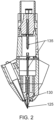
- FIG. 2 shows a cut-away side view of an embodiment for a multi-mode laser device for metal manufacturing applications featuring its supply and laser connections.
- FIG. 2 shows additional features from FIG. 1 . Shown in FIG. 2 are a central axis wire material guide channel (135) and a central deposition nozzle (130).
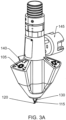
- FIG. 3A and FIG. 3B show a perspective and expanded view of an embodiment for a multi-mode laser device for metal manufacturing applications illustrating its plurality of laser beams (115) emanating from a plurality of laser light sources (105), including but not exclusively, external fiber-coupled diode laser(s) or external fiber-coupled diode-pumped solid state laser(s) (DPSSL), or internal fiber-coupled or fiber-free solid-state diode lasers.
- DPSSL fiber-coupled diode laser
- DPSSL fiber-coupled diode-pumped solid state laser
- the multiple lasers are configured as insertable laser assemblies (140) which are precision adjustable and securable with locking mechanisms (140) to deliver high-effective power to a precisely oriented focal point (120) comprising the energy source of the laser manufacturing process. Also shown in FIG. 3A and FIG. 3B are the mounting structure for the multi-mode laser device (145) and a central deposition nozzle (130).
- the plurality of off-axis laser beams (115) emanating from a plurality of laser light sources (105), including but not exclusively, external fiber-coupled diode laser(s) or external fiber-coupled diode-pumped solid state laser(s) (DPSSL), or internal fiber-coupled or fiber-free solid-state diode lasers provides laser energy to a precisely oriented focal point (120) comprising the energy source of the laser manufacturing processes described in FIG. 12 for AM, laser cladding or laser welding (non-autogenous mode) using metal wire and metal powder (independently or simultaneously) through with a plurality of off-axis laser beams and FIG. 13 for laser welding (autogenous mode), laser cutting, laser texturing and laser polishing with a plurality of off-axis laser beams.
- the plurality of off-axis laser light sources (105) deliver laser beams (115) to the focal point of the laser manufacturing processes (120).
- the design of the insertable laser assemblies which are precision adjustable and securable with locking mechanisms (140), allows for precisely aligning the of off-axis laser light sources (105) to ensure that the laser beams (115) converge to the focal point of the laser manufacturing process (120).
- the design of the multi-mode laser device allows for angular variation in the inclination of the laser beams (115) from vertical, to facilitate process optimization for energy efficiency of the melting zone created at the focal point of the laser beams (120), and optimization against other considerations such as minimizing the possibility of specular reflection (either back reflection or reflection into another laser lens/fiber assembly) which could damage the laser light sources (105).
- the plurality of off-axis laser beams (115) are inclined 1 to 30 degrees from vertical. In some embodiments the plurality of off-axis laser beams (115) are inclined 30 to 60 degrees from vertical.
- the mounting structure for the multi-mode laser device (145) enables securing the laser device within a print enclosure, robotic system, gantry system, or computer numeric control system, or another machine.
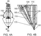
- FIG. 4A and Fig. 4B show a perspective and cut-away view of an external fiber-coupled insertable laser assembly for an embodiment of a multi-mode laser device for metal manufacturing applications, illustrating the arrangement of the laser fibers (150), laser fiber couplings (155), collimation and focusing optics (160), laser beam apertures (110), shield gas protection (170) and cooling system (165).
- Each laser beam aperture (110) encloses its respective laser beam (115) and is designed with a precisely manufactured aperture at its exit point to minimize the possibility of specular reflection (either back reflection or reflection into another laser lens/fiber assembly) which could damage the laser light sources (105).
- Protective shield gas is delivered through the shield gas protection channel (170) to reduce the potential for particulate, dust or smoke entering the laser beam aperture (110) and causing damage to the collimation and focusing optics (160).
- the protective shield gas delivered through the shield gas protection channel (170) also facilitates the delivery of an inert gas to the focal point of the laser manufacturing process (120), which is desirable for AM, laser cladding, laser welding, laser cutting, laser texturing and laser polishing processes to reduce oxidation in the heat affected zone.
- the main body of the multi-mode laser device provides structure and support for the insertable laser assemblies.
- the off-axis configuration of laser light sources (105) allows for the incorporation of a single or multiple laser beams (115) in the multi-mode laser device.
- three off-axis laser light sources (105) are employed, with 120 degree rotational symmetry between each laser light source (105), although other off-axis configurations are viable and may be used in some embodiments.
- the design benefits from the off-axis laser architecture because it allows for scaling of laser power by incorporating additional laser light sources (105) circumferentially, and by allowing for on-axis powder and wire material feeds, as illustrated and discussed for FIG. 7 and FIG. 8 .
- the plurality of laser light sources (105) emit laser light of an infrared spectrum light at a wavelength of between approximately 700 nm and 1 mm. In some embodiments, the plurality of laser light sources emit laser light of a visible spectrum light at a wavelengths of between approximately 400 and 700 nm. In some embodiments, the plurality of laser light sources emit laser light of an ultraviolet spectrum light at a wavelength of between approximately 180 and 400 nm. Other wavelengths may be used as suitable to the feed materials used in the laser manufacturing process.
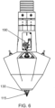
- FIG. 5A and FIG. 5B show a perspective and cut-away view of an internal fiber-coupled or fiber-free insertable laser assembly for an embodiment of a multi-mode laser device for metal manufacturing applications, illustrating the arrangement of the internal solid state diode laser(s) (175), collimation and focusing optics (160), shield gas protection (170), back-reflection protection (185), integrated aiming beam (180), and cooling system (165).
- collimation and focusing optics (160), back-reflection protection (185) and integrated aiming beam (180) may vary in other embodiments depending on constraints associated with the laser manufacturing application which could require additional laser power, additional protection feature (185) is achieved through a photosensor which is positioned to receive and detect back-reflection and permit rapid momentary deactivation of the respective laser assembly.
- the design shown in FIG. 5A and FIG. 5B is flexible to allow the incorporation of a single or multiple internal solid state diode laser(s) (175) within each internal fiber-coupled or fiber-free insertable laser assembly, which allows for an increase in the maximum laser power delivered to the process through the incorporation of additional solid state diode lasers (175) in each laser assembly.
- the arrangement of the collimation and focusing optics (160), back-reflection protection (185) and integrated aiming beam (180) may be adjusted, however, the basic architecture and concept remains the same as shown in FIG. 5 .
- the main body of the multi-mode laser device provides structure and support for the insertable laser assemblies.
- the off-axis configuration of laser light sources (105) allows for the incorporation of a single or multiple laser beams (115) in the multi-mode laser device.
- three off-axis laser light sources (105) are employed, with 120 degree rotational symmetry between each laser light source (105), although other off-axis configurations are viable and may be used in some embodiments.
- the design benefits from the off-axis laser architecture because it allows for scaling of laser power by incorporating additional laser light sources (105) circumferentially, and by allowing for on-axis powder and wire material feeds, as illustrated and discussed for FIG. 7 and FIG. 8 .
- the plurality of laser light sources (105) emit laser light of an infrared spectrum light at a wavelength of between approximately 700 nm and 1 mm. In some embodiments, the plurality of laser light sources emit laser light of a visible spectrum light at a wavelengths of between approximately 400 and 700 nm. In some embodiments, the plurality of laser light sources emit laser light of an ultraviolet spectrum light at a wavelength of between approximately 180 and 400 nm. Other wavelengths may be used as suitable to the feed materials used in the laser manufacturing process.
- FIG. 6 shows a perspective view of an embodiment for a multi-mode laser device for metal manufacturing applications featuring its integrated wire feed (pull) system (190). Also shown in FIG. 6 is the associated wire material guide channel (135).
- the integrated wire feed (pull) system (190) is housed within the mounting structure of the laser device (145, FIG. 3A ). In other embodiments, the integrated wire feed (pull) system (190) is situated outside the mounting structure of the laser device (145, FIG. 3A ).
- the integrated wire pull system (190) with automatic feed pressure control serves as a control mechanism for pulling deposition wire from the wire supply spool situated within the adjoining equipment and delivering deposition wire to the central deposition nozzle (130, FIG. 3A ) where it is used in laser manufacturing process for AM, laser cladding or laser welding (nonautogenous mode) by intersecting with the focal point of the laser beams (120).
- the feed pressure of the wire is regulated by automatically measuring the torque of the wire pull system (190) motor and adjusting the motor current to adjust wire feed rate and maintain a steady state wire feed pressure.
- the feed pressure of the wire is used in software to automatically modulate the power level of the laser beams (120) to provide optimal control of the metal deposition process.
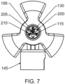
- FIG. 7 shows a bottom view of an embodiment for a multi-mode laser device for metal manufacturing applications featuring the underside of the device illustrating its central deposition nozzle (130) for supplying wire feed material (195), powder feed material nozzles (200) for supplying powder feed material (205), process gas orifices (210) and laser beams (115).
- FIG. 7 Not shown in FIG. 7 is an optional nozzle cowling (220, FIG. 9 ) which may be installed as shown in FIG. 9 for some embodiments of the multi-mode laser device.
- the nozzle cowling (220, FIG. 9 ) may provide improvements in the distribution of process and shield gas in some laser manufacturing applications.
- FIG. 8 shows a bottom view of an embodiment for a multi-mode laser device for metal manufacturing applications featuring two methods for delivering powder coaxially.
- the first method consists of a coaxial coniform powder feed material nozzle (215) which encloses the central deposition nozzle (130) and wire material guide channel (135) and provides a coniform distribution of powder coaxially to the focal point for wire, powder and laser beams (120, FIG. 1 ) at the working surface.
- the second method consists of multiple independent off-axis powder feed material nozzles (200) located circumferentially around the central deposition nozzle (130) providing individual collimated jets of powder to the focal point for wire, powder and laser beams (120, FIG. 1 ) at the working surface.
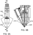
- FIG. 9A and FIG. 9B show a perspective and cut-away view of an embodiment for a multi-mode laser device for metal manufacturing applications featuring its process gas distribution and supply channels (210) to the working surface of the process, in conjunction with a detachable nozzle cowling (220).
- the detachable and optional nozzle cowling (220) may provide improvements in the distribution of process and shield gas in some laser manufacturing applications.
- the process gas channels (210) provide the capability to supply inert gas, for example argon, to the focal point for wire, powder and laser beams (120, FIG. 1 ) at the working surface.
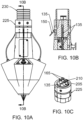
- FIG. 10A, FIG. 10B and FIG 10C show a perspective, cut-away and expanded view of an embodiment for a multi-mode laser device for metal manufacturing applications featuring its head supply neck coupling (225) which facilitates a quick-disconnect and rapid reconnection of the laser device to the incoming supply lines contained in the supply conduit (230).
- the supply lines comprise electrical (245), water cooling (165), process gas (210), wire material guide channel (135) and powder feed channel (205) quick disconnect/reconnect connections, in addition to routing/management (235) of laser fibers (150) for external fiber-coupled diode laser(s) or external fiber-coupled DPSSLs.
- the water cooling line fittings (165) provide an inlet and exit for cooling water to maintain the multi-mode laser device at operational temperature.
- the coolant may be a liquid fluid, such as water.
- FIG. 10B Also shown in FIG. 10B are cone shaped features of the wire material guide channel (135) which help to guide the wire material from the supply conduit (230) through the supply neck coupling (225) and into the wire material guide channel (135) of the multi-mode laser device.
- these cone shaped features also facilitate the passage and interchange of wires when more than one metal wire is used in the process.
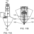
- FIG. 11A and FIG. 11B show a perspective and cut-away view of an embodiment for a multi-mode laser device for metal manufacturing applications featuring a wire material position sensor (240) for automatically detecting the tip of the wire feed material (195) as it is retracted through the central deposition nozzle (130) and into the wire material guide channel (135).
- the wire material position sensor uses a photoelectric, capacitive or hall-effect electrical sensor to automatically control the precise distance of the multi-mode laser device central deposition nozzle (130) tip to the working surface by using the wire feed material (195) as a distance measuring probe.
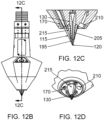
- FIG. 12A , FIG. 12B, FIG. 12C, and FIG. 12D show a method for AM, laser cladding or laser welding (non-autogenous mode) using metal wire (195) and metal powder (205), independently or simultaneously, through a single device with a plurality of off-axis laser beams (115).
- the metal powder feed can be supplied via a coaxial powder feed material nozzle (215, FIG. 8 ) which encloses the central deposition nozzle (130, FIG. 8 ) and wire material guide channel (135, FIG. 8 ) or through multiple independent off-axis powder feed material nozzles (200, FIG. 8 ) located circumferentially around the central deposition nozzle (130, FIG. 8 ) providing individual collimated jets of powder to the focal point for wire, powder and laser beams (120, FIG. 1 ) at the working surface.
- a coaxial powder feed material nozzle (215, FIG. 8 ) which encloses the central deposition nozzle (130, FIG. 8 ) and
- step 305 manually positioning the multi-mode laser device at the correct working distance OR utilizing the metal wire material (195), the wire material position sensor (240, FIG. 11 ) situated in the wire material guide channel (135, FIG. 11 ) and the integrated wire pull system (190, FIG. 6 ) automatic feed pressure control to precisely measure the working distance of the multi-mode laser device and automatically adjust its position as necessary utilizing the software and kinematics of the 3D metal printer, CNC machine, laser cell, laser-safe enclosure, or robotic or gantry system to which it is installed.
- step 310 activating the supply of metal wire (195) through the central deposition nozzle (130) and/or the supply of metal powder (205) through either a coaxial coniform powder feed material nozzle (215) or plurality of powder feed material nozzles (200) located circumferentially around the central deposition nozzle (130).
- step 315 activating a plurality of off-axis laser light sources (105) to generate and guide laser light beams (115) through laser beam apertures (110) to enable melting of a wire material feed (195), and/or a powder feed material (205) at a focal point for wire, powder and laser beams (120) at the work surface.
- step 320 delivering shield gas concurrently via the metal powder orifice (210), and/or the shield gas protection channel (170), and/or the coaxial powder feed material nozzle (215).
- step 325 creating a sequentially layered 3-dimensional metal construct by melting and fusing the wire feed material (195) and/or powder feed material (205) with the metal substrate (working surface).
- step 330 utilizing the integrated wire pull system (190, FIG. 6 ) automatic wire feed pressure control to precisely control the wire material (195) feed rate and/or modulate the power level of the laser beams (120) to control the metal deposition process.
- step 335 utilizing the metal wire material (195), the wire material position sensor (240, FIG. 11 ) and the integrated wire pull system (190, FIG. 6 ) automatic feed pressure control to periodically measure the build height of the fabricated metal construct and automatically adjust the working distance to ensure the focal point for wire, powder and laser beams (120) are always corrected aligned at the work surface.
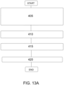
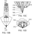
- FIG. 13 A , FIG. 13B, FIG. 13C, and FIG. 13D show a method for laser welding (autogenous mode), laser cutting, laser texturing and laser polishing through a single device with a plurality of off-axis laser beams (115).
- metal powder and metal wire feedstock are not used by the process and only the laser beams (115) are employed.
- the metal powder feed channels coaxial nozzle (215, FIG. 8 ) and/or multiple independent off-axis powder feed material nozzles (200, FIG. 8 )
- metal wire material (195) may be present and used for the purpose of serving as a distance measuring probe as described in step 405.
- step 405 manually positioning the multi-mode laser device at the correct working distance OR utilizing the metal wire material (195), the wire material position sensor (240, FIG. 11 ) situated in the wire material guide channel (135, FIG. 11 ) and the integrated wire pull system (190, FIG. 6 ) automatic feed pressure control to precisely measure the working distance of the multi-mode laser device and automatically adjust its position as necessary utilizing the software and kinematics of the 3D metal printer, CNC machine, laser cell, laser-safe enclosure, or robotic or gantry system to which it is installed.
- step 410 activating a plurality of off-axis laser light sources (105) to generate and guide laser light beams (115) through laser beam apertures (110) to enable laser welding (autogenous mode), laser cutting, laser texturing and laser polishing.
- step 415 delivering shield gas concurrently via the metal powder orifice (210), and/or the shield gas protection channel (170), and/or the coaxial powder feed material nozzle (215).
- step 420 performing laser welding (autogenous mode), laser cutting, laser texturing and laser polishing.
Landscapes
- Engineering & Computer Science (AREA)
- Optics & Photonics (AREA)
- Physics & Mathematics (AREA)
- Plasma & Fusion (AREA)
- Mechanical Engineering (AREA)
- Materials Engineering (AREA)
- Chemical & Material Sciences (AREA)
- Manufacturing & Machinery (AREA)
- Health & Medical Sciences (AREA)
- Toxicology (AREA)
- General Health & Medical Sciences (AREA)
- Laser Beam Processing (AREA)
- Powder Metallurgy (AREA)
Claims (15)
- Un dispositif laser multimode comprenant :un système intégré de traction de fil (190) avec contrôle automatique de la pression d'alimentation capable de fournir un fil métallique (195) à partir d'un tube de guidage d'alimentation de fil à axe central à travers une buse de dépôt centrale (130) dans le boîtier de dépôt simultané à un point focal (120) pour le fil, la poudre et le laserune pluralité de sources lumineuses laser hors axe (105) pour délivrer des faisceaux lumineux laser (115) à un point focal (120) sur la surface de travail, dans laquelle la pluralité de sources lumineuses laser hors axe (105) comprend une pluralité d'assemblages laser comprenant des lasers à diode interne à l'état solide comprenant une protection contre la rétro-réflexion (185),un système de distribution de gaz de protection (170) capable de fournir du gaz de protection au point focal (120) pour le fil, la poudre et le laser,un système de refroidissement (165), etdans lequel le dispositif laser multimode est capable de réaliser la fabrication additive (AM) (120), le rechargement par laser, le soudage laser autogène et non autogène, la découpe laser, la texturation laser et le polissage laser, et de réaliser la fabrication additive en utilisant simultanément un fil métallique et une poudre métallique, grâce à la mise en oeuvre de canaux coaxiaux indépendants d'alimentation en fil métallique (215) et en poudre (200),caractérisé par le fait que la pluralité de sources de lumière laser hors axe (105) comprend une pluralité d'assemblages laser insérables (140) et que la protection contre la rétro-réflexion (185) se matérialise dans un photocapteur pour détecter la rétro-réflexion et permettre une désactivation momentanée rapide par rapport à l'assemblage laser respectif.
- Le dispositif laser multimode de la revendication 1, dans lequel la pluralité de sources de lumière laser hors axe (105) comprend une pluralité de lasers à diodes à l'état solide couplés à des fibres externes, ou une pluralité de lasers à l'état solide pompés par des diodes couplés à des fibres externes, ou une pluralité de lasers à diodes à l'état solide couplés à des fibres internes, ou une pluralité de lasers à diodes à l'état solide sans fibres internes.
- Le dispositif laser multimode de la revendication 1, dans lequel la pluralité de sources de lumière laser hors axe (105) comprend une pluralité d'assemblages laser insérables comprenant des mécanismes de verrouillage sécurisés (140) et capables d'ajustement de précision et de fournir une puissance efficace élevée à un point focal orienté avec précision (120).
- Le dispositif laser multimode de la revendication 1, dans lequel la pluralité d'assemblages laser insérables comprend une pluralité de lasers à diodes internes à l'état solide (175) capables d'accueillir plusieurs lasers à diodes dans un même assemblage laser pour faciliter l'augmentation de la puissance laser.
- Le dispositif laser multimode de la revendication 1, dans lequel la pluralité d'assemblages laser insérables comprend une pluralité de lasers internes à diode à l'état solide (175), chacun coordonné à un assemblage laser respectif et capable d'orienter un faisceau pour aider à l'alignement de l'assemblage laser respectif.
- Le dispositif laser multimode de la revendication 1, dans lequel la pluralité de sources de lumière laser (105) émet une lumière laser d'un spectre infrarouge, d'un spectre visible ou d'un spectre ultraviolet.
- Le dispositif laser multimode de la revendication 1, comprenant en outre un couvercle amovible de gaz de protection (170) pour diffuser le gaz de protection sur une surface de travail.
- Le dispositif laser multimode de la revendication 1, dans lequel plusieurs ensembles de lentilles de lumière laser hors axe sont inclinés de 1 à 60 degrés inclusivement par rapport à la verticale.
- Le dispositif laser multimode de la revendication 1, dans lequel le canal d'alimentation en fil comprend un capteur de position du matériau du fil (240) pour détecter automatiquement une pointe d'un matériau d'alimentation en fil (195) lorsque le matériau d'alimentation en fil est rétracté à travers la buse de dépôt centrale et dans un canal de guidage du matériau du fil.
- Le dispositif laser multimode de la revendication 9, dans lequel le capteur de position du matériau du fil (240) comprend un capteur électrique photoélectrique, capacitif ou à effet Hall capable de contrôler automatiquement une distance précise entre l'extrémité d'une buse de dépôt centrale d'un dispositif laser multimode et une surface de travail en détectant la position exacte de l'extrémité du matériau d'alimentation du fil lorsque le matériau d'alimentation du fil est rétracté vers le haut à travers le canal de guidage du matériau du fil, et en calculant une commande de pression d'alimentation automatique du système de tirage de fil intégré pour insérer le fil à une distance exacte d'un point focal du processus de fabrication par laser.
- Le dispositif laser multimode de la revendication 1, dans lequel la poudre est délivrée coaxialement au moyen d'une buse conique (215) imbriquée autour du canal d'alimentation du fil ou au moyen de plusieurs buses de poudre indépendantes hors axe (200) fournissant des jets collimatés individuels de poudre situés autour du canal d'alimentation du fil.
- Le dispositif laser multimode de la revendication 1, dans lequel le dispositif laser multimode est capable de fabrication additive, de rechargement par laser et de soudage laser non autogène avec au moins un fil métallique et une poudre métallique (210) délivrés avec une pluralité de faisceaux laser hors axe comprenant une pluralité de paramètres de processus variables définis par l'utilisateur de la vitesse de dépôt, de la puissance du laser, du contrôle de la pression du fil et de la vitesse d'alimentation en fil/poudre entrés comme signaux de commande et capables d'optimiser la qualité du dépôt.
- Le dispositif laser multimode de la revendication 12, comprenant en outre des gradients de matériau et un mélange de matériaux en mélangeant des poudres dans la buse de dépôt ou en amont de la buse de dépôt à partir de plusieurs alimentations en poudre ou en mélangeant des poudres sur une matrice d'alimentation en fil, ou en mélangeant plusieurs fils.
- Le dispositif laser multimode de la revendication 1, dans lequel le dispositif laser multimode consiste en un dispositif unique composé d'une tête de dépôt d'alimentation, d'une pluralité de faisceaux laser hors axe (115), d'un système de commande de processus en ligne et d'au moins une buse de matériau d'alimentation en poudre (200), d'un pilote d'alimentation en fil (195) et d'une commande de précision capable d'utiliser le matériau d'alimentation en fil comme sonde de mesure de la distance, et d'un bouclier de gaz de protection.
- Le dispositif laser multimode de la revendication 14, dans lequel au moins une buse d'alimentation en poudre (200) comprend une buse d'alimentation en poudre hors axe ou une buse d'alimentation en poudre coaxiale.
Priority Applications (1)
| Application Number | Priority Date | Filing Date | Title |
|---|---|---|---|
| EP22202227.9A EP4183513A1 (fr) | 2019-07-03 | 2019-11-15 | Dispositif laser multimode pour applications de fabrication métallique |
Applications Claiming Priority (3)
| Application Number | Priority Date | Filing Date | Title |
|---|---|---|---|
| US201962870651P | 2019-07-03 | 2019-07-03 | |
| US16/683,236 US11219951B2 (en) | 2019-07-03 | 2019-11-13 | Multi-mode laser device for metal manufacturing applications |
| PCT/EP2019/081509 WO2021001054A1 (fr) | 2019-07-03 | 2019-11-15 | Dispositif laser multimode pour applications de fabrication métallique |
Related Child Applications (2)
| Application Number | Title | Priority Date | Filing Date |
|---|---|---|---|
| EP22202227.9A Division EP4183513A1 (fr) | 2019-07-03 | 2019-11-15 | Dispositif laser multimode pour applications de fabrication métallique |
| EP22202227.9A Division-Into EP4183513A1 (fr) | 2019-07-03 | 2019-11-15 | Dispositif laser multimode pour applications de fabrication métallique |
Publications (2)
| Publication Number | Publication Date |
|---|---|
| EP3993943A1 EP3993943A1 (fr) | 2022-05-11 |
| EP3993943B1 true EP3993943B1 (fr) | 2023-08-23 |
Family
ID=74065961
Family Applications (2)
| Application Number | Title | Priority Date | Filing Date |
|---|---|---|---|
| EP22202227.9A Pending EP4183513A1 (fr) | 2019-07-03 | 2019-11-15 | Dispositif laser multimode pour applications de fabrication métallique |
| EP19806165.7A Active EP3993943B1 (fr) | 2019-07-03 | 2019-11-15 | Dispositif laser multimode pour applications de fabrication métallique |
Family Applications Before (1)
| Application Number | Title | Priority Date | Filing Date |
|---|---|---|---|
| EP22202227.9A Pending EP4183513A1 (fr) | 2019-07-03 | 2019-11-15 | Dispositif laser multimode pour applications de fabrication métallique |
Country Status (7)
| Country | Link |
|---|---|
| US (1) | US11219951B2 (fr) |
| EP (2) | EP4183513A1 (fr) |
| JP (1) | JP7471002B2 (fr) |
| KR (1) | KR20220025079A (fr) |
| CN (1) | CN113950388B (fr) |
| IL (1) | IL288598A (fr) |
| WO (1) | WO2021001054A1 (fr) |
Families Citing this family (40)
| Publication number | Priority date | Publication date | Assignee | Title |
|---|---|---|---|---|
| US12365142B2 (en) * | 2019-09-20 | 2025-07-22 | Shibaura Machine Co., Ltd. | Additive manufacturing system |
| IT202000006016A1 (it) * | 2020-03-20 | 2021-09-20 | Comau Spa | "Apparecchiatura per assemblare celle di batteria o moduli di batteria" |
| US12415229B2 (en) | 2020-07-29 | 2025-09-16 | Blue Origin Manufacturing, LLC | Friction stir welding systems and methods |
| DE102021200684A1 (de) | 2021-01-26 | 2022-07-28 | Trumpf Laser- Und Systemtechnik Gmbh | Verfahren zum Laserschweißen von Blechteilen und Laserschweißanlage |
| US11745268B2 (en) * | 2021-05-13 | 2023-09-05 | Xerox Corporation | Melted metal level sensor for a metal drop ejecting three-dimensional (3D) object printer |
| CN113319426B (zh) * | 2021-05-20 | 2022-06-17 | 华中科技大学 | 一种用于激光焊接焊缝增强的激光填粉装置和填粉方法 |
| CN113319294B (zh) * | 2021-06-28 | 2022-03-08 | 南昌航空大学 | 一种可拆卸式光内送粉激光增材制造熔覆头 |
| CN113478521B (zh) * | 2021-07-14 | 2022-12-30 | 东莞科卓机器人有限公司 | 一种气路电路共用的水平关节机器人 |
| WO2022152335A1 (fr) * | 2021-08-25 | 2022-07-21 | Comtes Fht A.S. | Plaque de construction pour appareil de fabrication additive ayant un système de sorties de canaux traversant la plaque de construction et conçu pour transférer un gaz au-dessus de la surface de dépôt |
| CN113828803A (zh) * | 2021-10-07 | 2021-12-24 | 哈尔滨理工大学 | 一种全方位调节加压的同轴送粉喷嘴装置 |
| CN114603161B (zh) * | 2022-03-09 | 2022-12-09 | 华中科技大学 | 一种同轴胶体粉末辅助熔丝增材制造装置及其制造方法 |
| CN114682805B (zh) * | 2022-04-18 | 2023-07-28 | 中国人民解放军32181部队 | 送粉喷嘴及增材制造方法 |
| CN114888303B (zh) * | 2022-05-09 | 2024-03-15 | 广东粤港澳大湾区硬科技创新研究院 | 一种蓝色激光增材制造装置 |
| US20240001444A1 (en) * | 2022-06-29 | 2024-01-04 | Xerox Corporation | Liquid metal ejector level sense system and methods thereof |
| EP4558301A2 (fr) * | 2022-07-22 | 2025-05-28 | Laser Mechanisms, Inc. | Appareil et procédé pour le dépôt de fil laser par focalisation en anneau en utilisant un faisceau à divisions multiples |
| CN115365517A (zh) * | 2022-09-30 | 2022-11-22 | 江苏理工学院 | 一种金属熔覆增材与修复高效成形装置及成形方法 |
| EP4349600A1 (fr) * | 2022-10-07 | 2024-04-10 | Helmholtz-Zentrum hereon GmbH | Procédé de fonctionnement d'un dispositif d'application de matériau à base de fil et dispositif d'application de matériau à base de fil |
| US12605791B2 (en) | 2022-10-27 | 2026-04-21 | Directedmetal 3D Sl | Laser devices and methods for laser metal deposition |
| CN115816829B (zh) * | 2022-10-28 | 2024-02-23 | 南京航空航天大学 | 3d打印预浸丝输送与剪断功能集成装置及运行方法 |
| CN115647389A (zh) * | 2022-11-24 | 2023-01-31 | 哈尔滨理工大学 | 多区域连续增材制造激光成型方法 |
| CN116021038B (zh) * | 2022-12-14 | 2025-05-09 | 大连理工大学 | 一种丝粉同轴激光制造方法及装置 |
| CN116445906B (zh) * | 2022-12-29 | 2025-07-25 | 淮南联合大学 | 一种激光增材设备的出粉装置 |
| CN116511542A (zh) * | 2023-02-07 | 2023-08-01 | 安徽艾密克电联科技有限责任公司 | 一种转运式现场激光增材修复设备 |
| CN116213952B (zh) * | 2023-02-16 | 2023-08-22 | 浙江芯源交通电子有限公司 | 一种激光切割设备 |
| US12140109B2 (en) | 2023-03-30 | 2024-11-12 | Blue Origin, Llc | Transpiration-cooled systems having permeable and non-permeable portions |
| US12172229B2 (en) | 2023-03-30 | 2024-12-24 | Blue Origin, Llc | Friction stir additive manufacturing devices and methods for forming in-situ rivets |
| US12246392B2 (en) | 2023-03-30 | 2025-03-11 | Blue Origin Manufacturing, LLC | Deposition head for friction stir additive manufacturing devices and methods |
| CN116550992B (zh) * | 2023-04-10 | 2025-09-16 | 江苏科技大学 | 一种粉末传递优化可控的直接激光沉积系统及其方法 |
| CN116372375B (zh) * | 2023-05-19 | 2026-04-21 | 苏州融速智造科技有限公司 | 偏转布置多激光搅拌熔池的增材设备及方法 |
| CN117245210B (zh) * | 2023-11-17 | 2024-02-02 | 苏州融速智造科技有限公司 | 非均匀能量分布的多激光映射合成方法及其系统 |
| WO2024239821A1 (fr) * | 2023-05-19 | 2024-11-28 | 苏州融速智造科技有限公司 | Dispositif additif et procédé d'agencement de déviation de multiples lasers pour agiter un bain de fusion, et procédé de synthèse par mappage multi-laser pour une distribution d'énergie non-uniforme, et système pour celui-ci |
| US12383975B2 (en) | 2023-08-03 | 2025-08-12 | Blue Origin Manufacturing, LLC | Friction stir additive manufacturing formed parts and structures with integrated passages |
| US12303994B2 (en) | 2023-08-03 | 2025-05-20 | Blue Origin Manufacturing, LLC | Friction stir additive manufacturing formed parts and structures with integrated passages |
| CN117364076B (zh) * | 2023-10-07 | 2024-09-17 | 中原工学院 | 一种带有强制水冷系统的高速激光熔覆系统及熔覆方法 |
| US20250135581A1 (en) * | 2023-10-31 | 2025-05-01 | Additec LLC | Method and system for incorporating a melted metal drop ejecting device in a hybrid additive manufacturing system |
| US12589446B2 (en) | 2023-12-12 | 2026-03-31 | Blue Origin Manufacturing, LLC | Wire-feed friction stir additive manufacturing systems, devices, and methods |
| KR102926750B1 (ko) * | 2023-12-13 | 2026-02-13 | 두산에너빌리티 주식회사 | 동축 레이저 용접 시스템 |
| CN117921189B (zh) * | 2024-03-18 | 2025-01-10 | 南京英尼格玛工业自动化技术有限公司 | 同轴丝粉同送的多波长光源电弧复合激光加工头及方法 |
| WO2026028049A1 (fr) | 2024-07-30 | 2026-02-05 | Istituto Nazionale Di Fisica Nucleare | Procédé de fabrication de cavités d'accélération de particules supraconductrices et/ou normalement conductrices, et cavités d'accélération obtenues à partir dudit procédé |
| CN118848248B (zh) * | 2024-08-15 | 2026-01-27 | 南京航空航天大学 | 一种面向异种难焊材料的焊接成分设计装置及粉量配比需求判别自适应调控方法 |
Family Cites Families (38)
| Publication number | Priority date | Publication date | Assignee | Title |
|---|---|---|---|---|
| US4323756A (en) | 1979-10-29 | 1982-04-06 | United Technologies Corporation | Method for fabricating articles by sequential layer deposition |
| DD296436A5 (de) * | 1990-07-09 | 1991-12-05 | Zentralinstitut Fuer Schweisstechnik Der Ddr,De | Laserschweisskopf mit axialer zufuehrung von zusatzwerkstoffen bzw. schutzgas |
| US6122564A (en) * | 1998-06-30 | 2000-09-19 | Koch; Justin | Apparatus and methods for monitoring and controlling multi-layer laser cladding |
| US7765022B2 (en) | 1998-06-30 | 2010-07-27 | The P.O.M. Group | Direct metal deposition apparatus utilizing rapid-response diode laser source |
| WO2003017745A2 (fr) * | 2001-08-23 | 2003-03-06 | Sciperio, Inc. | Instrument d'architecture et procedes d'utilisation |
| RU2005102091A (ru) * | 2002-06-28 | 2005-07-10 | Фоутонами Инк. (Ca) | Нечувствительный обратному отражению электрооптический интерфейс и способ сопряжения его с волноводом |
| JP4505190B2 (ja) * | 2003-03-27 | 2010-07-21 | 新日本製鐵株式会社 | レーザ切断装置 |
| DE102004031097B4 (de) * | 2004-06-28 | 2012-02-09 | Diehl Bgt Defence Gmbh & Co. Kg | Lasermessgerät |
| JP2007007698A (ja) * | 2005-06-30 | 2007-01-18 | Mitsubishi Heavy Ind Ltd | レーザ加工ヘッド |
| US7949031B2 (en) * | 2006-06-16 | 2011-05-24 | Pbc Lasers Gmbh | Optoelectronic systems providing high-power high-brightness laser light based on field coupled arrays, bars and stacks of semicondutor diode lasers |
| US20100133424A1 (en) * | 2007-05-26 | 2010-06-03 | Norman Matheson Lindsay | Electro-optical sensors |
| US20120074110A1 (en) * | 2008-08-20 | 2012-03-29 | Zediker Mark S | Fluid laser jets, cutting heads, tools and methods of use |
| CN101733550B (zh) | 2010-01-09 | 2012-04-25 | 苏州大学 | 一种送丝送粉复合激光熔覆成形方法及装置 |
| CN102812533B (zh) * | 2010-04-07 | 2015-12-02 | Fei公司 | 组合激光器和带电粒子束系统 |
| US20110304854A1 (en) * | 2010-06-14 | 2011-12-15 | Si Li | Instantaneous, phase measuring interferometer apparatus and method |
| ES3061078T3 (en) * | 2010-09-25 | 2026-03-31 | Ipg Photonics Canada Inc | Aparatus and method for coherent imaging and feedback control for modification of materials |
| EP2667998B1 (fr) * | 2011-01-27 | 2020-11-18 | Bystronic Laser AG | Machine de traitement au laser ainsi que procédé permettant de centrer un faisceau focalisé |
| JP6027814B2 (ja) * | 2012-08-07 | 2016-11-16 | 株式会社アマダホールディングス | レーザ加工装置 |
| FR2998818B1 (fr) * | 2012-11-30 | 2020-01-31 | Association Pour La Recherche Et Le Developpement De Methodes Et Processus Industriels "Armines" | Procede de fabrication d'une piece par fusion de poudre les particules de poudre arrivant froides dans le bain |
| US20150255105A1 (en) * | 2014-03-07 | 2015-09-10 | Mediatek Inc. | Method for controlling power of laser emitting unit and associated apparatus |
| WO2015186751A1 (fr) * | 2014-06-04 | 2015-12-10 | 三菱日立パワーシステムズ株式会社 | Système de réparation, dispositif fournissant des données de réparation et procédé de production de données de réparation |
| CN111151749A (zh) * | 2014-11-14 | 2020-05-15 | 株式会社尼康 | 造形装置及造形方法 |
| US20170050268A1 (en) | 2015-03-24 | 2017-02-23 | Technology Research Association For Future Additive Manufacturing | Processing nozzle, processing head, and machining apparatus |
| DK3756817T3 (da) * | 2016-01-12 | 2023-06-12 | Mestek Machinery Inc | Laserskæreværktøj med en omhyllende beskyttelsesanordning med sammenlåsningsomskiftere, fremgangsmåde til montering af sådant laserskæreværktøj |
| DE102016201418A1 (de) * | 2016-01-29 | 2017-08-03 | Kjellberg-Stiftung | Vorrichtung und Verfahren zur thermischen Bearbeitung |
| US9821399B1 (en) * | 2016-07-08 | 2017-11-21 | Norsk Titanium As | Wire arc accuracy adjustment system |
| JP2018047485A (ja) * | 2016-09-21 | 2018-03-29 | 株式会社アマダホールディングス | レーザ加工機におけるレーザ戻り光検出装置および方法 |
| JP6732627B2 (ja) * | 2016-10-19 | 2020-07-29 | 浜松ホトニクス株式会社 | レーザ光照射装置 |
| CN107083550A (zh) | 2017-02-21 | 2017-08-22 | 机械科学研究总院先进制造技术研究中心 | 一种温度、送粉量可自动调试智能激光熔覆头 |
| CN206543876U (zh) * | 2017-03-02 | 2017-10-10 | 南通金源智能技术有限公司 | 一种金属3d打印设备的循环净化装置 |
| US10661343B2 (en) * | 2017-05-02 | 2020-05-26 | Additec Additive Technologies, LLC | Smart additive manufacturing device |
| US10589377B2 (en) * | 2017-07-06 | 2020-03-17 | Ii-Vi Delaware Inc. | Additive manufacturing in metals with a fiber array laser source and adaptive multi-beam shaping |
| CN107505715B (zh) * | 2017-09-05 | 2020-05-05 | 福建工程学院 | 一种完全环状激光熔覆头 |
| DE102017215839B4 (de) * | 2017-09-07 | 2026-03-26 | Sauer Gmbh | Optikmodul mit Vorrichtung zum automatischen Wechseln einer Kollimationsoptik |
| CN208019599U (zh) * | 2018-02-02 | 2018-10-30 | 天津市宇航兴达真空设备制造有限公司 | 一种气体保护焊双盘连续送丝随动装置 |
| CN108637251B (zh) | 2018-05-09 | 2020-04-21 | 西安增材制造国家研究院有限公司 | 一种具有层高控制功能的增材制造设备及层高控制方法 |
| CN109338359A (zh) | 2018-12-14 | 2019-02-15 | 西安中科中美激光科技有限公司 | 一种多束金属粉流与多束激光精准匹配的高速激光熔覆头 |
| IL290911B2 (en) * | 2019-08-27 | 2026-01-01 | Edison Welding Inst Inc | Optical system with coaxial laser wire for use in additive manufacturing |
-
2019
- 2019-11-13 US US16/683,236 patent/US11219951B2/en not_active Expired - Fee Related
- 2019-11-15 JP JP2021577882A patent/JP7471002B2/ja active Active
- 2019-11-15 CN CN201980097374.0A patent/CN113950388B/zh active Active
- 2019-11-15 EP EP22202227.9A patent/EP4183513A1/fr active Pending
- 2019-11-15 KR KR1020227003552A patent/KR20220025079A/ko not_active Ceased
- 2019-11-15 EP EP19806165.7A patent/EP3993943B1/fr active Active
- 2019-11-15 WO PCT/EP2019/081509 patent/WO2021001054A1/fr not_active Ceased
-
2021
- 2021-12-01 IL IL288598A patent/IL288598A/en unknown
Also Published As
| Publication number | Publication date |
|---|---|
| CN113950388A (zh) | 2022-01-18 |
| CN113950388B (zh) | 2024-04-19 |
| JP2022549988A (ja) | 2022-11-30 |
| US11219951B2 (en) | 2022-01-11 |
| WO2021001054A1 (fr) | 2021-01-07 |
| IL288598A (en) | 2022-02-01 |
| EP4183513A1 (fr) | 2023-05-24 |
| US20210001402A1 (en) | 2021-01-07 |
| EP3993943A1 (fr) | 2022-05-11 |
| KR20220025079A (ko) | 2022-03-03 |
| JP7471002B2 (ja) | 2024-04-19 |
Similar Documents
| Publication | Publication Date | Title |
|---|---|---|
| EP3993943B1 (fr) | Dispositif laser multimode pour applications de fabrication métallique | |
| US10661343B2 (en) | Smart additive manufacturing device | |
| US11478881B2 (en) | Optical module having a device for automatically changing a collimation optic | |
| US11927825B2 (en) | Exchangeable optical module for a laser machining machine | |
| US4673795A (en) | Integrated robotic laser material processing and imaging system | |
| KR102251657B1 (ko) | 다중빔 섬유 레이저 시스템 | |
| RU2317183C2 (ru) | Ручная питаемая порошком горелка для лазерной сварки плавлением | |
| KR102520120B1 (ko) | 추가 레이저 기계가공 시스템 및 방법 | |
| EP3330038B1 (fr) | Tête de revêtement laser et procédé d'exploitation d'un système de revêtement laser | |
| EP3986658B1 (fr) | Appareil de traitement au laser et procédé correspondant de traitement au laser | |
| CN116372375B (zh) | 偏转布置多激光搅拌熔池的增材设备及方法 | |
| EP3766627B1 (fr) | Oscillateur laser, dispositif d'usinage laser l'utilisant, et procédé d'oscillation laser | |
| CN104289811A (zh) | 一种多光束中心送丝激光加工头及其加工方法 | |
| CA2387157A1 (fr) | Dispositif comprenant au moins une source lumineuse formee par plusieurs sources lumineuses individuelles | |
| US20210362276A1 (en) | Laser end effector, and corresponding laser machine tool and manufacturing method | |
| KR102675028B1 (ko) | 접근하기 어려운 공작물의 레이저 가공장치 | |
| JPH10314973A (ja) | 複合レーザビームによるレーザ加工装置および加工法 | |
| JP3595511B2 (ja) | レーザ加工ヘッド及びこれを備えたレーザ加工装置 | |
| JP2022548628A (ja) | 材料供給装置 | |
| US20240375183A1 (en) | Print heads for additive manufacturing apparatuses | |
| Bachmann | Diode Laser Systems |
Legal Events
| Date | Code | Title | Description |
|---|---|---|---|
| STAA | Information on the status of an ep patent application or granted ep patent |
Free format text: STATUS: UNKNOWN |
|
| STAA | Information on the status of an ep patent application or granted ep patent |
Free format text: STATUS: THE INTERNATIONAL PUBLICATION HAS BEEN MADE |
|
| PUAI | Public reference made under article 153(3) epc to a published international application that has entered the european phase |
Free format text: ORIGINAL CODE: 0009012 |
|
| STAA | Information on the status of an ep patent application or granted ep patent |
Free format text: STATUS: REQUEST FOR EXAMINATION WAS MADE |
|
| 17P | Request for examination filed |
Effective date: 20211216 |
|
| AK | Designated contracting states |
Kind code of ref document: A1 Designated state(s): AL AT BE BG CH CY CZ DE DK EE ES FI FR GB GR HR HU IE IS IT LI LT LU LV MC MK MT NL NO PL PT RO RS SE SI SK SM TR |
|
| DAV | Request for validation of the european patent (deleted) | ||
| DAX | Request for extension of the european patent (deleted) | ||
| REG | Reference to a national code |
Ref country code: DE Ref legal event code: R079 Free format text: PREVIOUS MAIN CLASS: B23K0026060000 Ipc: B22F0010850000 Ref country code: DE Ref legal event code: R079 Ref document number: 602019035751 Country of ref document: DE Free format text: PREVIOUS MAIN CLASS: B23K0026060000 Ipc: B22F0010850000 |
|
| GRAP | Despatch of communication of intention to grant a patent |
Free format text: ORIGINAL CODE: EPIDOSNIGR1 |
|
| STAA | Information on the status of an ep patent application or granted ep patent |
Free format text: STATUS: GRANT OF PATENT IS INTENDED |
|
| RIC1 | Information provided on ipc code assigned before grant |
Ipc: B23K 26/342 20140101ALI20230427BHEP Ipc: B23K 26/14 20140101ALI20230427BHEP Ipc: B23K 26/06 20140101ALI20230427BHEP Ipc: B33Y 50/02 20150101ALI20230427BHEP Ipc: B33Y 30/00 20150101ALI20230427BHEP Ipc: B23K 26/70 20140101ALI20230427BHEP Ipc: B23K 26/211 20140101ALI20230427BHEP Ipc: B22F 12/55 20210101ALI20230427BHEP Ipc: B22F 12/53 20210101ALI20230427BHEP Ipc: B22F 12/45 20210101ALI20230427BHEP Ipc: B22F 12/41 20210101ALI20230427BHEP Ipc: B22F 10/85 20210101AFI20230427BHEP |
|
| INTG | Intention to grant announced |
Effective date: 20230602 |
|
| GRAS | Grant fee paid |
Free format text: ORIGINAL CODE: EPIDOSNIGR3 |
|
| GRAA | (expected) grant |
Free format text: ORIGINAL CODE: 0009210 |
|
| STAA | Information on the status of an ep patent application or granted ep patent |
Free format text: STATUS: THE PATENT HAS BEEN GRANTED |
|
| AK | Designated contracting states |
Kind code of ref document: B1 Designated state(s): AL AT BE BG CH CY CZ DE DK EE ES FI FR GB GR HR HU IE IS IT LI LT LU LV MC MK MT NL NO PL PT RO RS SE SI SK SM TR |
|
| REG | Reference to a national code |
Ref country code: GB Ref legal event code: FG4D |
|
| REG | Reference to a national code |
Ref country code: CH Ref legal event code: EP |
|
| REG | Reference to a national code |
Ref country code: IE Ref legal event code: FG4D |
|
| REG | Reference to a national code |
Ref country code: DE Ref legal event code: R096 Ref document number: 602019035751 Country of ref document: DE |
|
| REG | Reference to a national code |
Ref country code: LT Ref legal event code: MG9D |
|
| REG | Reference to a national code |
Ref country code: NL Ref legal event code: MP Effective date: 20230823 |
|
| REG | Reference to a national code |
Ref country code: AT Ref legal event code: MK05 Ref document number: 1601989 Country of ref document: AT Kind code of ref document: T Effective date: 20230823 |
|
| PG25 | Lapsed in a contracting state [announced via postgrant information from national office to epo] |
Ref country code: GR Free format text: LAPSE BECAUSE OF FAILURE TO SUBMIT A TRANSLATION OF THE DESCRIPTION OR TO PAY THE FEE WITHIN THE PRESCRIBED TIME-LIMIT Effective date: 20231124 |
|
| PG25 | Lapsed in a contracting state [announced via postgrant information from national office to epo] |
Ref country code: IS Free format text: LAPSE BECAUSE OF FAILURE TO SUBMIT A TRANSLATION OF THE DESCRIPTION OR TO PAY THE FEE WITHIN THE PRESCRIBED TIME-LIMIT Effective date: 20231223 |
|
| PG25 | Lapsed in a contracting state [announced via postgrant information from national office to epo] |
Ref country code: SE Free format text: LAPSE BECAUSE OF FAILURE TO SUBMIT A TRANSLATION OF THE DESCRIPTION OR TO PAY THE FEE WITHIN THE PRESCRIBED TIME-LIMIT Effective date: 20230823 Ref country code: RS Free format text: LAPSE BECAUSE OF FAILURE TO SUBMIT A TRANSLATION OF THE DESCRIPTION OR TO PAY THE FEE WITHIN THE PRESCRIBED TIME-LIMIT Effective date: 20230823 Ref country code: PT Free format text: LAPSE BECAUSE OF FAILURE TO SUBMIT A TRANSLATION OF THE DESCRIPTION OR TO PAY THE FEE WITHIN THE PRESCRIBED TIME-LIMIT Effective date: 20231226 Ref country code: NO Free format text: LAPSE BECAUSE OF FAILURE TO SUBMIT A TRANSLATION OF THE DESCRIPTION OR TO PAY THE FEE WITHIN THE PRESCRIBED TIME-LIMIT Effective date: 20231123 Ref country code: NL Free format text: LAPSE BECAUSE OF FAILURE TO SUBMIT A TRANSLATION OF THE DESCRIPTION OR TO PAY THE FEE WITHIN THE PRESCRIBED TIME-LIMIT Effective date: 20230823 Ref country code: LV Free format text: LAPSE BECAUSE OF FAILURE TO SUBMIT A TRANSLATION OF THE DESCRIPTION OR TO PAY THE FEE WITHIN THE PRESCRIBED TIME-LIMIT Effective date: 20230823 Ref country code: LT Free format text: LAPSE BECAUSE OF FAILURE TO SUBMIT A TRANSLATION OF THE DESCRIPTION OR TO PAY THE FEE WITHIN THE PRESCRIBED TIME-LIMIT Effective date: 20230823 Ref country code: IS Free format text: LAPSE BECAUSE OF FAILURE TO SUBMIT A TRANSLATION OF THE DESCRIPTION OR TO PAY THE FEE WITHIN THE PRESCRIBED TIME-LIMIT Effective date: 20231223 Ref country code: HR Free format text: LAPSE BECAUSE OF FAILURE TO SUBMIT A TRANSLATION OF THE DESCRIPTION OR TO PAY THE FEE WITHIN THE PRESCRIBED TIME-LIMIT Effective date: 20230823 Ref country code: GR Free format text: LAPSE BECAUSE OF FAILURE TO SUBMIT A TRANSLATION OF THE DESCRIPTION OR TO PAY THE FEE WITHIN THE PRESCRIBED TIME-LIMIT Effective date: 20231124 Ref country code: FI Free format text: LAPSE BECAUSE OF FAILURE TO SUBMIT A TRANSLATION OF THE DESCRIPTION OR TO PAY THE FEE WITHIN THE PRESCRIBED TIME-LIMIT Effective date: 20230823 Ref country code: AT Free format text: LAPSE BECAUSE OF FAILURE TO SUBMIT A TRANSLATION OF THE DESCRIPTION OR TO PAY THE FEE WITHIN THE PRESCRIBED TIME-LIMIT Effective date: 20230823 |
|
| PG25 | Lapsed in a contracting state [announced via postgrant information from national office to epo] |
Ref country code: PL Free format text: LAPSE BECAUSE OF FAILURE TO SUBMIT A TRANSLATION OF THE DESCRIPTION OR TO PAY THE FEE WITHIN THE PRESCRIBED TIME-LIMIT Effective date: 20230823 |
|
| PG25 | Lapsed in a contracting state [announced via postgrant information from national office to epo] |
Ref country code: ES Free format text: LAPSE BECAUSE OF FAILURE TO SUBMIT A TRANSLATION OF THE DESCRIPTION OR TO PAY THE FEE WITHIN THE PRESCRIBED TIME-LIMIT Effective date: 20230823 |
|
| PG25 | Lapsed in a contracting state [announced via postgrant information from national office to epo] |
Ref country code: SM Free format text: LAPSE BECAUSE OF FAILURE TO SUBMIT A TRANSLATION OF THE DESCRIPTION OR TO PAY THE FEE WITHIN THE PRESCRIBED TIME-LIMIT Effective date: 20230823 Ref country code: RO Free format text: LAPSE BECAUSE OF FAILURE TO SUBMIT A TRANSLATION OF THE DESCRIPTION OR TO PAY THE FEE WITHIN THE PRESCRIBED TIME-LIMIT Effective date: 20230823 Ref country code: ES Free format text: LAPSE BECAUSE OF FAILURE TO SUBMIT A TRANSLATION OF THE DESCRIPTION OR TO PAY THE FEE WITHIN THE PRESCRIBED TIME-LIMIT Effective date: 20230823 Ref country code: EE Free format text: LAPSE BECAUSE OF FAILURE TO SUBMIT A TRANSLATION OF THE DESCRIPTION OR TO PAY THE FEE WITHIN THE PRESCRIBED TIME-LIMIT Effective date: 20230823 Ref country code: DK Free format text: LAPSE BECAUSE OF FAILURE TO SUBMIT A TRANSLATION OF THE DESCRIPTION OR TO PAY THE FEE WITHIN THE PRESCRIBED TIME-LIMIT Effective date: 20230823 Ref country code: CZ Free format text: LAPSE BECAUSE OF FAILURE TO SUBMIT A TRANSLATION OF THE DESCRIPTION OR TO PAY THE FEE WITHIN THE PRESCRIBED TIME-LIMIT Effective date: 20230823 Ref country code: SK Free format text: LAPSE BECAUSE OF FAILURE TO SUBMIT A TRANSLATION OF THE DESCRIPTION OR TO PAY THE FEE WITHIN THE PRESCRIBED TIME-LIMIT Effective date: 20230823 |
|
| REG | Reference to a national code |
Ref country code: DE Ref legal event code: R097 Ref document number: 602019035751 Country of ref document: DE |
|
| PG25 | Lapsed in a contracting state [announced via postgrant information from national office to epo] |
Ref country code: IT Free format text: LAPSE BECAUSE OF FAILURE TO SUBMIT A TRANSLATION OF THE DESCRIPTION OR TO PAY THE FEE WITHIN THE PRESCRIBED TIME-LIMIT Effective date: 20230823 |
|
| PLBE | No opposition filed within time limit |
Free format text: ORIGINAL CODE: 0009261 |
|
| STAA | Information on the status of an ep patent application or granted ep patent |
Free format text: STATUS: NO OPPOSITION FILED WITHIN TIME LIMIT |
|
| REG | Reference to a national code |
Ref country code: CH Ref legal event code: PL |
|
| PG25 | Lapsed in a contracting state [announced via postgrant information from national office to epo] |
Ref country code: MC Free format text: LAPSE BECAUSE OF FAILURE TO SUBMIT A TRANSLATION OF THE DESCRIPTION OR TO PAY THE FEE WITHIN THE PRESCRIBED TIME-LIMIT Effective date: 20230823 |
|
| PG25 | Lapsed in a contracting state [announced via postgrant information from national office to epo] |
Ref country code: LU Free format text: LAPSE BECAUSE OF NON-PAYMENT OF DUE FEES Effective date: 20231115 |
|
| PG25 | Lapsed in a contracting state [announced via postgrant information from national office to epo] |
Ref country code: CH Free format text: LAPSE BECAUSE OF NON-PAYMENT OF DUE FEES Effective date: 20231130 |
|
| 26N | No opposition filed |
Effective date: 20240524 |
|
| PG25 | Lapsed in a contracting state [announced via postgrant information from national office to epo] |
Ref country code: MC Free format text: LAPSE BECAUSE OF FAILURE TO SUBMIT A TRANSLATION OF THE DESCRIPTION OR TO PAY THE FEE WITHIN THE PRESCRIBED TIME-LIMIT Effective date: 20230823 Ref country code: LU Free format text: LAPSE BECAUSE OF NON-PAYMENT OF DUE FEES Effective date: 20231115 Ref country code: CH Free format text: LAPSE BECAUSE OF NON-PAYMENT OF DUE FEES Effective date: 20231130 Ref country code: SI Free format text: LAPSE BECAUSE OF FAILURE TO SUBMIT A TRANSLATION OF THE DESCRIPTION OR TO PAY THE FEE WITHIN THE PRESCRIBED TIME-LIMIT Effective date: 20230823 |
|
| REG | Reference to a national code |
Ref country code: BE Ref legal event code: MM Effective date: 20231130 |
|
| REG | Reference to a national code |
Ref country code: IE Ref legal event code: MM4A |
|
| PG25 | Lapsed in a contracting state [announced via postgrant information from national office to epo] |
Ref country code: IE Free format text: LAPSE BECAUSE OF NON-PAYMENT OF DUE FEES Effective date: 20231115 |
|
| PG25 | Lapsed in a contracting state [announced via postgrant information from national office to epo] |
Ref country code: BE Free format text: LAPSE BECAUSE OF NON-PAYMENT OF DUE FEES Effective date: 20231130 |
|
| PG25 | Lapsed in a contracting state [announced via postgrant information from national office to epo] |
Ref country code: IE Free format text: LAPSE BECAUSE OF NON-PAYMENT OF DUE FEES Effective date: 20231115 Ref country code: BE Free format text: LAPSE BECAUSE OF NON-PAYMENT OF DUE FEES Effective date: 20231130 |
|
| PG25 | Lapsed in a contracting state [announced via postgrant information from national office to epo] |
Ref country code: BG Free format text: LAPSE BECAUSE OF FAILURE TO SUBMIT A TRANSLATION OF THE DESCRIPTION OR TO PAY THE FEE WITHIN THE PRESCRIBED TIME-LIMIT Effective date: 20230823 |
|
| PG25 | Lapsed in a contracting state [announced via postgrant information from national office to epo] |
Ref country code: BG Free format text: LAPSE BECAUSE OF FAILURE TO SUBMIT A TRANSLATION OF THE DESCRIPTION OR TO PAY THE FEE WITHIN THE PRESCRIBED TIME-LIMIT Effective date: 20230823 |
|
| PG25 | Lapsed in a contracting state [announced via postgrant information from national office to epo] |
Ref country code: CY Free format text: LAPSE BECAUSE OF FAILURE TO SUBMIT A TRANSLATION OF THE DESCRIPTION OR TO PAY THE FEE WITHIN THE PRESCRIBED TIME-LIMIT; INVALID AB INITIO Effective date: 20191115 |
|
| PG25 | Lapsed in a contracting state [announced via postgrant information from national office to epo] |
Ref country code: HU Free format text: LAPSE BECAUSE OF FAILURE TO SUBMIT A TRANSLATION OF THE DESCRIPTION OR TO PAY THE FEE WITHIN THE PRESCRIBED TIME-LIMIT; INVALID AB INITIO Effective date: 20191115 |
|
| PG25 | Lapsed in a contracting state [announced via postgrant information from national office to epo] |
Ref country code: TR Free format text: LAPSE BECAUSE OF FAILURE TO SUBMIT A TRANSLATION OF THE DESCRIPTION OR TO PAY THE FEE WITHIN THE PRESCRIBED TIME-LIMIT Effective date: 20230823 |
|
| PGFP | Annual fee paid to national office [announced via postgrant information from national office to epo] |
Ref country code: DE Payment date: 20251128 Year of fee payment: 7 |
|
| PGFP | Annual fee paid to national office [announced via postgrant information from national office to epo] |
Ref country code: GB Payment date: 20251127 Year of fee payment: 7 |
|
| PGFP | Annual fee paid to national office [announced via postgrant information from national office to epo] |
Ref country code: FR Payment date: 20251125 Year of fee payment: 7 |