EP3994012B1 - Umwandelbares rad zum überqueren jeglicher art von gelände und autonomer roboter mit mindestens einem solchen rad - Google Patents
Umwandelbares rad zum überqueren jeglicher art von gelände und autonomer roboter mit mindestens einem solchen rad Download PDFInfo
- Publication number
- EP3994012B1 EP3994012B1 EP20735423.4A EP20735423A EP3994012B1 EP 3994012 B1 EP3994012 B1 EP 3994012B1 EP 20735423 A EP20735423 A EP 20735423A EP 3994012 B1 EP3994012 B1 EP 3994012B1
- Authority
- EP
- European Patent Office
- Prior art keywords
- wheel
- axis
- rotation
- sliding
- branches
- Prior art date
- Legal status (The legal status is an assumption and is not a legal conclusion. Google has not performed a legal analysis and makes no representation as to the accuracy of the status listed.)
- Active
Links
Images


Classifications
-
- B—PERFORMING OPERATIONS; TRANSPORTING
- B25—HAND TOOLS; PORTABLE POWER-DRIVEN TOOLS; MANIPULATORS
- B25J—MANIPULATORS; CHAMBERS PROVIDED WITH MANIPULATION DEVICES
- B25J5/00—Manipulators mounted on wheels or on carriages
- B25J5/007—Manipulators mounted on wheels or on carriages mounted on wheels
-
- B—PERFORMING OPERATIONS; TRANSPORTING
- B60—VEHICLES IN GENERAL
- B60B—VEHICLE WHEELS; CASTORS; AXLES FOR WHEELS OR CASTORS; INCREASING WHEEL ADHESION
- B60B19/00—Wheels not otherwise provided for or having characteristics specified in one of the subgroups of this group
- B60B19/04—Wheels not otherwise provided for or having characteristics specified in one of the subgroups of this group expansible
-
- B—PERFORMING OPERATIONS; TRANSPORTING
- B60—VEHICLES IN GENERAL
- B60B—VEHICLE WHEELS; CASTORS; AXLES FOR WHEELS OR CASTORS; INCREASING WHEEL ADHESION
- B60B19/00—Wheels not otherwise provided for or having characteristics specified in one of the subgroups of this group
- B60B19/02—Wheels not otherwise provided for or having characteristics specified in one of the subgroups of this group convertible, e.g. from road wheel to rail wheel; Wheels specially designed for alternative use on road and rail
-
- B—PERFORMING OPERATIONS; TRANSPORTING
- B60—VEHICLES IN GENERAL
- B60B—VEHICLE WHEELS; CASTORS; AXLES FOR WHEELS OR CASTORS; INCREASING WHEEL ADHESION
- B60B2900/00—Purpose of invention
- B60B2900/30—Increase in
- B60B2900/351—Increase in versatility, e.g. usable for different purposes or different arrangements
-
- B—PERFORMING OPERATIONS; TRANSPORTING
- B60—VEHICLES IN GENERAL
- B60B—VEHICLE WHEELS; CASTORS; AXLES FOR WHEELS OR CASTORS; INCREASING WHEEL ADHESION
- B60B2900/00—Purpose of invention
- B60B2900/50—Improvement of
- B60B2900/551—Handling of obstacles or difficult terrains
-
- B—PERFORMING OPERATIONS; TRANSPORTING
- B60—VEHICLES IN GENERAL
- B60Y—INDEXING SCHEME RELATING TO ASPECTS CROSS-CUTTING VEHICLE TECHNOLOGY
- B60Y2200/00—Type of vehicle
- B60Y2200/40—Special vehicles
- B60Y2200/47—Climbing vehicles, e.g. facade climbing devices
- B60Y2200/48—Stair-climbing vehicles
-
- G—PHYSICS
- G05—CONTROLLING; REGULATING
- G05D—SYSTEMS FOR CONTROLLING OR REGULATING NON-ELECTRIC VARIABLES
- G05D1/00—Control of position, course, altitude or attitude of land, water, air or space vehicles, e.g. using automatic pilots
- G05D1/02—Control of position or course in two dimensions
- G05D1/021—Control of position or course in two dimensions specially adapted to land vehicles
Definitions
- the present invention relates to the technical field of autonomous robots and means equipping such robots to facilitate their movement on any type of terrain such as stairs and relates in particular to a transformable wheel adapted to cross any type of terrain and autonomous robot equipped with at least one such wheel.
- Transformable wheels in particular for wheelchairs for moving both on flat terrain and for overcoming obstacles such as stairs are known.
- a first position adapted for movement on flat ground, where the two parts are angularly offset relative to each other around the central axis so as to form a solid disc in the plane perpendicular to the axis of the wheel.
- a second position adapted for movement on stairs where the two distinct parts are angularly offset from one another around the axis of the wheel so that one of the parts completely covers the other.
- the two distinct parts being identical, they each form a disc of identical diameter whose circumference is permanently in contact with the ground and which when they are in their first position form an approximately continuous tread.
- the aim of the invention is to propose a wheel to enable rolling on any type of terrain and to facilitate the passage of obstacles such as steps of stairs and which overcome the aforementioned drawbacks.
- Another aim of the invention is to propose an autonomous robot provided with at least one such wheel.
- the wheel according to the invention comprises an external part 100 composed of at least one half-shell 101 shown in front view on the figure 1 according to an XY plane with reference to the frame of reference noted in the figure.
- the part 100 formed of the half-shell 101 is part of a circle defined by its center through which the axis of rotation 150 of the wheel passes and its diameter corresponding to the diameter of the wheel.
- the central axis of symmetry of the part 100 formed by the half-shell 101 passes through the axis of rotation 150 of the wheel and is parallel to the Z axis of the figures.
- the half-shell 101 includes a plurality of branches 110 identical and offset angularly relative to each other in a uniform manner.
- the number of branches is between three and ten and preferably equal to six.
- Each branch 110 comprises a leading edge 111, a trailing edge 113 and a distal edge 112 relative to the central axis of rotation 150.
- the exterior surface of each branch formed by the distal edge 112 is curved along a radius of curvature corresponding to the radius of curvature of the wheel.
- Each branch 110 has a pivot axis 120 located near the distal edge 112.
- the first part 100 formed of the half-shell 101 comprises three bearings 131, 132 and 133 equidistant from one another and located at equal distance from the axis of rotation 150.
- the half-shell 101 also comprises a ball bearing 160 located in a circle around the axis 150 and inside a circular recess 162.
- the wheel comprises a second part 200 shown seen from above on the figure 2 .
- the second part is planar, comprises a central axis of rotation passing through the axis of rotation 150 of the wheel and a plurality of branches 210 whose number corresponds to the number of branches 110 of the half-shell 101.
- the part 200 comprises a central through cavity 201 of circular shape whose diameter preferably corresponds to the diameter of the recess 160 of the half-shell 101.
- the part 200 comprises three circular arc grooves 231, 232 and 233 equidistant from one another and located at an equal distance from the axis of rotation 150.
- the three grooves 231 , 232 and 233 have an identical shape.
- Each of the three grooves 231, 232 and 233 have an upper edge and a lower edge parallel to the upper edge and located relative to it closer to the axis of rotation 150 and two end edges in the shape of a semicircle.
- Grooves 231, 232 and 233 are dimensioned so that the bearings 131, 132 and 133 can slide freely in it.
- the part 200 also includes in each of its branches 210 a curved groove 240 of elongated shape and constant width.
- Each groove 240 has two ends, a first end located on the side of the axis of rotation 150 and a second end on the side of the end of the branch 210.
- the first ends of the grooves 240 are aligned on the circumference of a first circle whose center coincides with the axis of symmetry of the part 200.
- the second ends of the grooves 240 are aligned on the circumference of a second circle whose center coincides with the axis of symmetry of the part 200 and whose diameter is larger than that of the first circle.
- the ends of the grooves located closest to the axis of rotation 150 are called proximal ends and referenced 241 and the ends located furthest from the axis of symmetry are called distal ends and are referenced 242.
- the wheel according to the invention also comprises a third part 300 composed of a plurality of teeth 310 whose number corresponds to the number of branches 110 and 210, therefore according to the preferred embodiment of the invention, the wheel has six teeth 310 identical, one of which is represented in perspective on the Figure 3 .
- Each tooth 310 has a curved outer surface 312 with a radius of curvature corresponding to the radius of curvature of the wheel.
- the tooth 310 also includes a through cavity 320 and a bearing 340 able to rotate freely around its axis which is parallel to the axis Z according to the reference frame indicated in the figures.
- part 200 of the wheel is placed on the first part formed by the half-shell 101 so that the bearings 131, 132 and 133 are inside the three respective grooves 231, 232 and 233. In this position, the axes of symmetry of the half-shell 101 and of the part 200 are aligned with the axis of rotation 150 of the wheel.
- Part 200 is movable relative to part 100. Part 200 can rotate around its axis of rotation between two positions.
- the grooves 231, 232 and 233 are dimensioned so that the bearings 131, 132 and 133 are pressed against their upper edge. This is to better distribute efforts.
- the teeth 310 are pivotally mounted on the first part 100 formed by the half-shell 101 and are driven by the movement of the second part 200.
- Each tooth 310 is located so that its through cavity is crossed by a pivot axis 120 of the half-shell 101 so that each tooth can rotate around the axis 120 to which it is connected.
- the bearing 340 of each tooth is located inside the groove 240 of the second part 200, the width of the groove 240 being dimensioned so that the bearing 340 can slide from the proximal end 341 of the groove at the distal end 342 and vice versa when the part 200 moves from one position to another.
- the bearings 340 of the teeth 310 are shown in dotted lines because they are located on the hidden face of the teeth 310 on the figures 4a and 4b .
- the teeth 310 are movable between two positions.
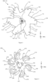
- the bearings 340 of the teeth 310 are located at the distal ends of the grooves 240 of the second part 200. This position corresponds to the closed position of the wheel. In this position, the teeth 310 are arranged so that their outer surface 312 is on the circumference of a circle of the diameter of the wheel. In this position the leading edges of the branches 110 of the half-shell 101 are not visible.
- the bearings 340 of the teeth 310 are located at the proximal ends of the grooves 240 of the second part 200.
- This position corresponds to the open position of the wheel.
- the teeth 310 are arranged in a star pattern and their outer surface 312 runs along the trailing edge 113 of the branches 110 of the half-shell 101 so that the leading edges 111 of the branches 110 of the half-shell 101 are apparent.
- the wheel according to the invention passes from one position to another thanks to mechanical means of cam and rollers as defined by mechanical parts 400 and 500 and detailed with reference to figures 5a, 5b , 6a and 6b and thanks to drive means external to the wheel.
- the sliding part 400 is shown in perspective on the figure 5a and top view on the figure 5b . It mainly comprises a cylinder 401, at least one bearing and preferably three bearings 431, 432 and 433 and a sliding axis 450 passing through the axis of symmetry of the cylinder 401.
- the three bearings are fixed on the lateral surface of the cylinder 401 at equidistant from each other and can rotate freely around their axis of rotation.
- the axes of rotation of the three bearings intersect on the axis of symmetry of the cylinder.
- the sliding part 400 cooperates with the part 500 and the two parts are represented together on the figures 6a and 6b .
- the part 500 in the shape of a hollow cylinder comprises in its center a through cavity 501 in the shape of a cylinder axis of symmetry passing through the axis of symmetry of the part 500.
- the part 500 has on its internal wall at least one groove and preferably three identical helical grooves located at the same height on the cylinder of the part 500. In this way, the first ends of each groove are equidistant from each other and are angularly offset from each other by an angle of 60 degrees as can be seen in the figures 6a and 6b with the visible ends 541, 542 and 543 of the respective grooves 531, 532 and 533.
- the first end of each groove is located at an angular distance from the second end of between 40 degrees and 60 degrees.
- the diameter of the through cavity is sized so that the cylinder 401 can slide inside freely without being obstructed by the walls.
- the bearings 431, 432 and 433 are dimensioned to slide in the grooves 531, 532 and 533 from one end to the other and vice versa.
- the part 500 rotates on its axis of symmetry by an angle equal to the angular distance separating the first ends of the grooves from the second ends of the grooves.
- the part 500 thus rotates from a first position illustrated on the figure 6a to a second position illustrated on the figure 6b .
- the part 500 plays the role of a rotating cylindrical cam with three helical grooves and the bearings are the rollers which move in the grooves when the sliding axis 450 moves in translation.
- the part 500 is fixed on the part 200 in the central part so that their axes of symmetry coincide and are aligned with each other as can be seen in the Figure 7 .
- the axis of symmetry of the part 500 is therefore aligned with the axis of rotation 150 of the wheel.
- the cylinder 401 is housed in the central cavity 501 of the second part 200.
- the translation of the sliding part 400 in the direction of the sliding axis 450 causes the part 500 to rotate around the sliding axis 450 thanks to the bearings 431, 432 and 433 which slide in the grooves 531, 532 and 533.
- the part 500 being integral with the part 200, it in turn causes it to rotate around the sliding axis 450 and therefore the rotation axis 150 of wheel.
- the mechanical system for moving from one position to another has the advantage of requiring no electrical energy input to the wheel.
- wheel 10 is shown complete in perspective. It is composed of the assembly of the external part 100, the mobile part 200, the teeth 310, and the parts 400 and 500 not visible in the figures.
- the external part 100 of the wheel also comprises a second half shell 102 of substantially identical shape to the first half shell 101 which covers the constituent parts of the wheel by attaching to the edges distal of the half shell 101.
- the circular external surface of the branches of the first part 100 forms a first part of the tread of the wheel.
- the external part 100 composed of two half-shells 101 and 102 reinforces the wheel, protects it from dust and makes it more aesthetic.
- the wheel 10 is mounted on an axle 12 provided with a sliding ring 15 sliding between two extreme positions.
- the ring 15 is connected to the sliding part 400 by its sliding axis 450 and is integral with this part so that the movement of the ring 15 causes the axis to move. sliding 450 and the sliding part 400.
- the two extreme positions of the ring 15 each correspond to an open or closed position of the wheel.
- the ring located in its position on the axis 12 closest to the wheel corresponds to the wheel in the closed position and the ring located on the axis 12 in its position furthest from the wheel corresponds to the wheel in the open position as we can see it respectively on the figures 8 and 9 .
- part 200 is in its first position.
- the wheel comprises a continuous tread consisting of the succession of exterior surfaces 312 of the teeth 310 separated by the circular exterior surfaces formed along the distal edges 112 of the part 100.
- the circular exterior surface of all the branches 110 of the first part 100 forms the first part of the tread of the wheel and the outer surface of all of the outer surfaces 312 of the teeth 310 forms the second part of the tread of the wheel.
- the assembly of the two outer surfaces constitutes the complete, circular tread of the wheel in its closed position. In this position, the wheel is perfectly adapted to flat terrain.
- the part 200 is in its second position and the wheel has leading edges substantially perpendicular to the circumferential parts of the tread.
- the wheel does not have a circular and continuous circumference and has a discontinuous tread suitable for crossing stairs.
- the wheel includes means for keeping the position of the open or closed wheel locked.
- At least one wheel as defined according to the invention can equip an autonomous robot.
- the robot comprises means for detecting the presence of a staircase or an obstacle to be crossed and a control device capable of receiving and processing the signals received from the means for detecting the presence of a staircase to be crossed. These means can be proximity sensors, cameras, etc.
- the control device controls the passage from the open position to the closed position of the wheel and vice versa. Thus, the control device controls the movement of the sliding ring depending on whether the robot goes from crossing flat terrain to uneven terrain such as a staircase and vice versa.
- the robot includes means for maintaining the position of the ring at one or more intermediate positions located between its two extreme positions. These means can be contained in the axis 12 of the wheel.
- the wheel can have intermediate positions between the closed position and the open position which correspond to uses on different floors.
- a first intermediate position corresponds to an opening of 50% of the teeth 310 adapts the robot to move on soft ground
- a second intermediate position corresponding to an opening of 20% of the teeth 310 adapts the robot to move on snow .
- the bearings 131, 132 and 133 of the first part 100 are located at an intermediate position between the two ends of the grooves 231, 232 and 233.
- the robot comprises means for controlling the opening of the teeth as a function of the quality of the ground and as a function of the speed of movement.
- the robot is preferably equipped with two wheels or four wheels as defined in the invention.
- the wheels are assembled two by two along a single axis of rotation passing through their center on a single axle or on an axle specific to each wheel.
Landscapes
- Engineering & Computer Science (AREA)
- Mechanical Engineering (AREA)
- Robotics (AREA)
- Handcart (AREA)
- Manipulator (AREA)
Claims (11)
- Rad (10), umfassend:- einen ersten Teil (100), der um eine zentrale Drehachse (150) drehend angetrieben wird und mit mehreren Schenkeln (110) versehen ist, die in einem Kreis liegen, dessen Durchmesser gleich dem Durchmesser des Rads ist, wobei die kreisförmige Außenfläche der Gesamtheit der Schenkel einen ersten Teil des Laufstreifens des Rads bildet,- einen zweiten Teil (200), der in Bezug auf den ersten Teil zwischen einer ersten Position und einer zweiten Position beweglich ist, wobei der zweite Teil mehrere Schenkel (210) umfasst, die in einem Kreis liegen, dessen Mittelpunkt durch die Drehachse (150) verläuft,- Mittel zum Wechseln aus einer Position in die andere und umgekehrt, wobei die erste Position einer geschlossenen Position des Rads entspricht, in der das Rad einen vollständigen kreisförmigen Umfang aufweist, der einen kontinuierlichen Laufstreifen bildet, und wobei die zweite Position einer offenen Position des Rads entspricht, in der das Rad keinen vollständigen kreisförmigen Umfang aufweist und einen diskontinuierlichen Laufstreifen bildet,dadurch gekennzeichnet, dass das Rad einen dritten Teil (300) umfasst, der aus mehreren Zähnen (310) zusammengesetzt ist, deren kreisförmige Außenfläche (312) einen zweiten Teil des Laufstreifens des Rads bildet, wobei die Zähne an Schwenkachsen (120) des ersten Teils schwenkbar montiert sind, durch die Bewegung des zweiten Teils angetrieben werden und zwischen zwei Positionen beweglich sind.
- Rad nach Anspruch 1, wobei die Mittel zum Wechseln aus der ersten Position in die zweite Position im Wesentlichen ein am ersten Teil (100) befestigtes mechanisches Teil (500) und ein mechanisches Gleitteil (400), das im Teil (500) in Richtung der Drehachse (150) des Rads translatorisch beweglich ist, umfassen, wobei die Bewegung des Gleitteils (400) die Drehung des Teils (500) bewirkt, das seinerseits den zweiten Teil (200) drehend antreibt.
- Rad nach Anspruch 2, wobei das mechanische Teil (500) die Form eines Hohlzylinders aufweist und an seiner Innenwand mindestens eine schraubenförmige Nut (531, 532, 533) umfasst, wobei das mechanische Gleitteil (400) mindestens ein Lager (431, 432, 433) umfasst, das in der Nut (531, 532, 533) von einem Ende zum anderen gleiten kann.
- Rad nach Anspruch 1, 2 oder 3, wobei das erste Teil (100) in seinem Mittelteil drei Lager (131, 132, 133) aufweist, die in gleichen Abständen zueinander und in gleichem Abstand zur Drehachse (150) angeordnet sind.
- Rad nach einem der Ansprüche 1 bis 4, wobei der zweite Teil (200) in seinem Mittelteil drei Nuten (231, 232, 233) aufweist, die kreisbogenförmig, in gleichen Abständen zueinander und in gleichem Abstand zur Drehachse (150) angeordnet sind, wobei die drei Nuten (231, 232, 233) eine identische Form aufweisen.
- Rad nach einem der Ansprüche 1 bis 5, wobei der zweite Teil (200) in jedem seiner Schenkel (210) eine gebogene Nut (240) mit einer länglichen Form und konstanter Breite aufweist, wobei jede Nut (240) ein erstes proximales Ende (241), das sich auf der Seite der Drehachse (150) befindet, und ein zweites distales Ende (242) auf der Seite des Endes des Schenkels (210) aufweist.
- Rad nach Anspruch 6, wobei die Zähne (310) jeweils ein Lager (340) umfassen, das innerhalb der Nut (240) des zweiten Teils (200) positioniert ist, wobei das Lager (340) vom proximalen Ende (341) der Nut zum distalen Ende (342) gleitet, wenn sich der Zahn um die Schwenkachse (120) dreht.
- Rad nach einem der Ansprüche 2 bis 7, das auf einer Achse (12) montiert ist, die mit einem Gleitring (15) versehen ist, der zwischen zwei Positionen gleitet und so mit dem Gleitteil (400) verbunden ist, dass die Bewegung des Rings (15) das Gleitteil (400) in Bewegung versetzt, wobei die beiden Endpositionen des Rings (15) einer offenen bzw. geschlossenen Position des Rads entsprechen.
- Rad nach einem der Ansprüche 1 bis 8, umfassend Mittel zum Halten des Rads in mindestens einer Zwischenposition zwischen der geschlossenen Position und der offenen Position.
- Autonomer mobiler Roboter, dadurch gekennzeichnet, dass er mit mindestens zwei Rädern nach einem der Ansprüche 1 bis 9 ausgestattet ist, wobei die Räder paarweise entlang einer einzigen, durch ihren Mittelpunkt verlaufenden Drehachse auf einer einzigen Achse oder auf einer eigenen Achse für jedes Rad angeordnet sind.
- Mobiler Roboter nach Anspruch 10, umfassend Mittel zur Erkennung von Treppenstufen oder Hindernissen.
Applications Claiming Priority (3)
| Application Number | Priority Date | Filing Date | Title |
|---|---|---|---|
| FR1907477A FR3098147B1 (fr) | 2019-07-04 | 2019-07-04 | Roue transformable adaptée pour franchir des escaliers et robot autonome équipé d’au moins une telle roue |
| FR1912639A FR3098148B1 (fr) | 2019-07-04 | 2019-11-12 | Roue transformable adaptée pour franchir tout type de terrain et robot autonome équipé d’au moins une telle roue |
| PCT/EP2020/068916 WO2021001571A1 (fr) | 2019-07-04 | 2020-07-04 | Roue transformable adaptée pour franchir tout type de terrain et robot autonome équipé d'au moins une telle roue |
Publications (3)
| Publication Number | Publication Date |
|---|---|
| EP3994012A1 EP3994012A1 (de) | 2022-05-11 |
| EP3994012B1 true EP3994012B1 (de) | 2024-03-27 |
| EP3994012C0 EP3994012C0 (de) | 2024-03-27 |
Family
ID=67587893
Family Applications (1)
| Application Number | Title | Priority Date | Filing Date |
|---|---|---|---|
| EP20735423.4A Active EP3994012B1 (de) | 2019-07-04 | 2020-07-04 | Umwandelbares rad zum überqueren jeglicher art von gelände und autonomer roboter mit mindestens einem solchen rad |
Country Status (7)
| Country | Link |
|---|---|
| US (1) | US20220266627A1 (de) |
| EP (1) | EP3994012B1 (de) |
| JP (1) | JP2022543987A (de) |
| CN (1) | CN114245773A (de) |
| FR (2) | FR3098147B1 (de) |
| MA (1) | MA56446A (de) |
| WO (2) | WO2021001570A1 (de) |
Families Citing this family (4)
| Publication number | Priority date | Publication date | Assignee | Title |
|---|---|---|---|---|
| IT202100000800A1 (it) * | 2021-01-18 | 2022-07-18 | Be Initia Srl | Apparecchiatura in grado di salire autonomamente lungo una rampa di gradini |
| CN113910829B (zh) * | 2021-11-19 | 2024-05-07 | 上海交通大学 | 可变形轮及可移动设备 |
| KR102643009B1 (ko) * | 2022-07-25 | 2024-02-29 | 한국로봇융합연구원 | 에어리스 타이어 및 에어리스 타이어의 모드 변경 방법 |
| US12517200B2 (en) | 2024-01-08 | 2026-01-06 | GE Precision Healthcare LLC | Coil elements of a radio frequency coil utilizing bundles of conductive fibers entwined together |
Family Cites Families (19)
| Publication number | Priority date | Publication date | Assignee | Title |
|---|---|---|---|---|
| JPS63269701A (ja) * | 1987-04-27 | 1988-11-08 | Yoshikata Rokusha | 回転足車輪 |
| US8764028B2 (en) | 2009-11-30 | 2014-07-01 | Kevin Mann | Stair climbing wheel with multiple configurations |
| KR20120071187A (ko) * | 2010-12-22 | 2012-07-02 | 삼성테크윈 주식회사 | 바퀴 및 이를 구비한 이동체 |
| CN102328704B (zh) * | 2011-07-27 | 2013-04-10 | 中国科学院深圳先进技术研究院 | 可展轮式移动机器人 |
| DE102011052615A1 (de) * | 2011-08-11 | 2013-02-14 | Hochschule Regensburg | Treppengehendes Rad |
| FR3000431A3 (fr) * | 2013-01-03 | 2014-07-04 | Janick Simeray | Roue a diametre variable |
| DE102013006692B4 (de) * | 2013-04-16 | 2020-10-01 | Iav Gmbh Ingenieurgesellschaft Auto Und Verkehr | Universelles autonomes Fahrgestell zum Transport von Funktions- und Lastträgervorrichtungen |
| DE102013006690B4 (de) * | 2013-04-16 | 2018-08-09 | Iav Gmbh Ingenieurgesellschaft Auto Und Verkehr | Rad zum Befahren von Treppen und Verfahren zum Befahren von Treppen mit einem Rad |
| JP6455057B2 (ja) * | 2014-10-03 | 2019-01-23 | 学校法人日本大学 | ロボット及び荷台 |
| KR101674084B1 (ko) * | 2015-04-20 | 2016-11-08 | 숭실대학교산학협력단 | 변형바퀴 |
| US10399382B2 (en) * | 2016-02-19 | 2019-09-03 | Matthew E. Welsh | Irrigation system propulsion wheels and methods of making |
| CN105774394B (zh) * | 2016-04-08 | 2018-10-09 | 重庆大学 | 具有变形轮的移动机器人 |
| FR3056148A1 (fr) | 2016-09-19 | 2018-03-23 | Cca | Systeme de roue et dispositif de transport associe |
| CN206579401U (zh) * | 2017-03-10 | 2017-10-24 | 中国石油大学(华东) | 一种新型越野车轮 |
| CN107244185B (zh) * | 2017-06-07 | 2023-05-30 | 苏嘉明 | 一种全地形刚性柔性切换轮 |
| CN107804114A (zh) * | 2017-10-10 | 2018-03-16 | 大连理工大学 | 一种可变轮径异形轮的多轮式全地形机器人 |
| CN108403318B (zh) * | 2018-03-29 | 2020-03-27 | 西安理工大学 | 一种可爬楼梯的变形车轮 |
| DE202018005552U1 (de) * | 2018-11-30 | 2019-02-11 | Rustam Azamatov | Ein Rad zum Befahren von weichem und hartem Untergrund und zum Befahren von Treppenstufen |
| WO2020180476A2 (en) * | 2019-02-15 | 2020-09-10 | Brigham Young University | Connected deployable arms off of cylindrical surfaces for increased mobility |
-
2019
- 2019-07-04 FR FR1907477A patent/FR3098147B1/fr active Active
- 2019-11-12 FR FR1912639A patent/FR3098148B1/fr active Active
-
2020
- 2020-07-04 WO PCT/EP2020/068915 patent/WO2021001570A1/fr not_active Ceased
- 2020-07-04 MA MA056446A patent/MA56446A/fr unknown
- 2020-07-04 CN CN202080056902.0A patent/CN114245773A/zh active Pending
- 2020-07-04 JP JP2022500514A patent/JP2022543987A/ja active Pending
- 2020-07-04 WO PCT/EP2020/068916 patent/WO2021001571A1/fr not_active Ceased
- 2020-07-04 US US17/624,603 patent/US20220266627A1/en not_active Abandoned
- 2020-07-04 EP EP20735423.4A patent/EP3994012B1/de active Active
Also Published As
| Publication number | Publication date |
|---|---|
| JP2022543987A (ja) | 2022-10-17 |
| WO2021001570A1 (fr) | 2021-01-07 |
| CN114245773A (zh) | 2022-03-25 |
| FR3098148B1 (fr) | 2021-07-23 |
| EP3994012C0 (de) | 2024-03-27 |
| US20220266627A1 (en) | 2022-08-25 |
| FR3098147A1 (fr) | 2021-01-08 |
| EP3994012A1 (de) | 2022-05-11 |
| WO2021001571A1 (fr) | 2021-01-07 |
| FR3098147B1 (fr) | 2021-07-23 |
| MA56446A (fr) | 2022-05-11 |
| FR3098148A1 (fr) | 2021-01-08 |
Similar Documents
| Publication | Publication Date | Title |
|---|---|---|
| EP3994012B1 (de) | Umwandelbares rad zum überqueren jeglicher art von gelände und autonomer roboter mit mindestens einem solchen rad | |
| EP2763859B1 (de) | Multidirectionales antreibbares rad und damit ausgerüstetes fahrzeug | |
| EP2844498B1 (de) | Kugelförmiges rad und fahrzeug mit diesem rad | |
| EP0398081B1 (de) | Antriebseinrichtung | |
| WO2008141676A1 (fr) | Mécanisme de direction, en particulier pour véhicules courts | |
| EP3083269B1 (de) | Kugelförmiges rad zum bewegen eines fahrzeuges und fahrzeug mit dem rad | |
| EP2482943B1 (de) | Mehrzweckschuh zum gehen und rollen mit sohlenintegrierten seitlichen klapprädern | |
| EP1278984B1 (de) | Ein motorgetriebener wagen fähig zur bewegung in einem zylindrischen stollen | |
| FR2767488A1 (fr) | Vehicule jouet telecommande avec des roues arriere a action gyroscopique | |
| FR3062625A1 (fr) | Systeme de roue et dispositif de transport associe | |
| WO2003055370A1 (fr) | Aspirateur a roue(s) arriere orientable(s). | |
| WO2018158445A1 (fr) | Roue omnidirectionnelle et véhicule mettant en oeuvre la roue | |
| CA2540813C (fr) | Systeme de guidage pour vehicule le long d'au moins un rail directeur | |
| EP2688784B1 (de) | Lenkmechanismus | |
| FR3010466A1 (fr) | Dispositif de renvoi d'angle a piece de couplage cooperant avec une barre de commande, pour un equipement transformable | |
| WO2018050370A1 (fr) | Système de roue et dispositif de transport associé | |
| WO2005073578A1 (fr) | Joint de transmission homocinetique | |
| FR2940191A1 (fr) | Essieu destine au support d'une roue directrice relie a la structure d'un vehicule par une pluralite de bras. | |
| CA3127270C (fr) | Dispositif d'assistance electrique | |
| FR2584648A1 (fr) | Dispositif de guidage notamment pour engin du type robot | |
| FR2732884A1 (fr) | Suceur d'aspirateur avec des roues arrieres | |
| FR2798122A1 (fr) | Table pour l'entrainement d'une charge a surface inferieure plate et ensemble d'orientation la comportant | |
| FR3155704A1 (fr) | Véhicule automobile pour franchissement d’obstacles | |
| WO2023041871A1 (fr) | Ensemble d'articulation d'une tête mobile de robot | |
| WO2025233579A1 (fr) | Dispositif de motorisation pour fauteuil roulant |
Legal Events
| Date | Code | Title | Description |
|---|---|---|---|
| STAA | Information on the status of an ep patent application or granted ep patent |
Free format text: STATUS: UNKNOWN |
|
| STAA | Information on the status of an ep patent application or granted ep patent |
Free format text: STATUS: THE INTERNATIONAL PUBLICATION HAS BEEN MADE |
|
| PUAI | Public reference made under article 153(3) epc to a published international application that has entered the european phase |
Free format text: ORIGINAL CODE: 0009012 |
|
| STAA | Information on the status of an ep patent application or granted ep patent |
Free format text: STATUS: REQUEST FOR EXAMINATION WAS MADE |
|
| 17P | Request for examination filed |
Effective date: 20220204 |
|
| AK | Designated contracting states |
Kind code of ref document: A1 Designated state(s): AL AT BE BG CH CY CZ DE DK EE ES FI FR GB GR HR HU IE IS IT LI LT LU LV MC MK MT NL NO PL PT RO RS SE SI SK SM TR |
|
| DAX | Request for extension of the european patent (deleted) | ||
| RAV | Requested validation state of the european patent: fee paid |
Extension state: TN Effective date: 20220204 Extension state: MD Effective date: 20220204 Extension state: MA Effective date: 20220204 |
|
| GRAP | Despatch of communication of intention to grant a patent |
Free format text: ORIGINAL CODE: EPIDOSNIGR1 |
|
| STAA | Information on the status of an ep patent application or granted ep patent |
Free format text: STATUS: GRANT OF PATENT IS INTENDED |
|
| INTG | Intention to grant announced |
Effective date: 20231012 |
|
| GRAS | Grant fee paid |
Free format text: ORIGINAL CODE: EPIDOSNIGR3 |
|
| GRAA | (expected) grant |
Free format text: ORIGINAL CODE: 0009210 |
|
| STAA | Information on the status of an ep patent application or granted ep patent |
Free format text: STATUS: THE PATENT HAS BEEN GRANTED |
|
| AK | Designated contracting states |
Kind code of ref document: B1 Designated state(s): AL AT BE BG CH CY CZ DE DK EE ES FI FR GB GR HR HU IE IS IT LI LT LU LV MC MK MT NL NO PL PT RO RS SE SI SK SM TR |
|
| REG | Reference to a national code |
Ref country code: GB Ref legal event code: FG4D Free format text: NOT ENGLISH |
|
| REG | Reference to a national code |
Ref country code: CH Ref legal event code: EP |
|
| REG | Reference to a national code |
Ref country code: DE Ref legal event code: R096 Ref document number: 602020027949 Country of ref document: DE |
|
| REG | Reference to a national code |
Ref country code: IE Ref legal event code: FG4D Free format text: LANGUAGE OF EP DOCUMENT: FRENCH |
|
| U01 | Request for unitary effect filed |
Effective date: 20240419 |
|
| U07 | Unitary effect registered |
Designated state(s): AT BE BG DE DK EE FI FR IT LT LU LV MT NL PT SE SI Effective date: 20240425 |
|
| PG25 | Lapsed in a contracting state [announced via postgrant information from national office to epo] |
Ref country code: GR Free format text: LAPSE BECAUSE OF FAILURE TO SUBMIT A TRANSLATION OF THE DESCRIPTION OR TO PAY THE FEE WITHIN THE PRESCRIBED TIME-LIMIT Effective date: 20240628 |
|
| PG25 | Lapsed in a contracting state [announced via postgrant information from national office to epo] |
Ref country code: RS Free format text: LAPSE BECAUSE OF FAILURE TO SUBMIT A TRANSLATION OF THE DESCRIPTION OR TO PAY THE FEE WITHIN THE PRESCRIBED TIME-LIMIT Effective date: 20240627 Ref country code: HR Free format text: LAPSE BECAUSE OF FAILURE TO SUBMIT A TRANSLATION OF THE DESCRIPTION OR TO PAY THE FEE WITHIN THE PRESCRIBED TIME-LIMIT Effective date: 20240327 |
|
| PG25 | Lapsed in a contracting state [announced via postgrant information from national office to epo] |
Ref country code: RS Free format text: LAPSE BECAUSE OF FAILURE TO SUBMIT A TRANSLATION OF THE DESCRIPTION OR TO PAY THE FEE WITHIN THE PRESCRIBED TIME-LIMIT Effective date: 20240627 Ref country code: NO Free format text: LAPSE BECAUSE OF FAILURE TO SUBMIT A TRANSLATION OF THE DESCRIPTION OR TO PAY THE FEE WITHIN THE PRESCRIBED TIME-LIMIT Effective date: 20240627 Ref country code: HR Free format text: LAPSE BECAUSE OF FAILURE TO SUBMIT A TRANSLATION OF THE DESCRIPTION OR TO PAY THE FEE WITHIN THE PRESCRIBED TIME-LIMIT Effective date: 20240327 Ref country code: GR Free format text: LAPSE BECAUSE OF FAILURE TO SUBMIT A TRANSLATION OF THE DESCRIPTION OR TO PAY THE FEE WITHIN THE PRESCRIBED TIME-LIMIT Effective date: 20240628 |
|
| U20 | Renewal fee for the european patent with unitary effect paid |
Year of fee payment: 5 Effective date: 20240731 |
|
| PG25 | Lapsed in a contracting state [announced via postgrant information from national office to epo] |
Ref country code: IS Free format text: LAPSE BECAUSE OF FAILURE TO SUBMIT A TRANSLATION OF THE DESCRIPTION OR TO PAY THE FEE WITHIN THE PRESCRIBED TIME-LIMIT Effective date: 20240727 |
|
| VS25 | Lapsed in a validation state [announced via postgrant information from nat. office to epo] |
Ref country code: MD Free format text: LAPSE BECAUSE OF FAILURE TO SUBMIT A TRANSLATION OF THE DESCRIPTION OR TO PAY THE FEE WITHIN THE PRESCRIBED TIME-LIMIT Effective date: 20240327 |
|
| PG25 | Lapsed in a contracting state [announced via postgrant information from national office to epo] |
Ref country code: SM Free format text: LAPSE BECAUSE OF FAILURE TO SUBMIT A TRANSLATION OF THE DESCRIPTION OR TO PAY THE FEE WITHIN THE PRESCRIBED TIME-LIMIT Effective date: 20240327 |
|
| PG25 | Lapsed in a contracting state [announced via postgrant information from national office to epo] |
Ref country code: ES Free format text: LAPSE BECAUSE OF FAILURE TO SUBMIT A TRANSLATION OF THE DESCRIPTION OR TO PAY THE FEE WITHIN THE PRESCRIBED TIME-LIMIT Effective date: 20240327 |
|
| PG25 | Lapsed in a contracting state [announced via postgrant information from national office to epo] |
Ref country code: CZ Free format text: LAPSE BECAUSE OF FAILURE TO SUBMIT A TRANSLATION OF THE DESCRIPTION OR TO PAY THE FEE WITHIN THE PRESCRIBED TIME-LIMIT Effective date: 20240327 |
|
| PG25 | Lapsed in a contracting state [announced via postgrant information from national office to epo] |
Ref country code: PL Free format text: LAPSE BECAUSE OF FAILURE TO SUBMIT A TRANSLATION OF THE DESCRIPTION OR TO PAY THE FEE WITHIN THE PRESCRIBED TIME-LIMIT Effective date: 20240327 |
|
| PG25 | Lapsed in a contracting state [announced via postgrant information from national office to epo] |
Ref country code: SK Free format text: LAPSE BECAUSE OF FAILURE TO SUBMIT A TRANSLATION OF THE DESCRIPTION OR TO PAY THE FEE WITHIN THE PRESCRIBED TIME-LIMIT Effective date: 20240327 |
|
| PG25 | Lapsed in a contracting state [announced via postgrant information from national office to epo] |
Ref country code: SM Free format text: LAPSE BECAUSE OF FAILURE TO SUBMIT A TRANSLATION OF THE DESCRIPTION OR TO PAY THE FEE WITHIN THE PRESCRIBED TIME-LIMIT Effective date: 20240327 Ref country code: SK Free format text: LAPSE BECAUSE OF FAILURE TO SUBMIT A TRANSLATION OF THE DESCRIPTION OR TO PAY THE FEE WITHIN THE PRESCRIBED TIME-LIMIT Effective date: 20240327 Ref country code: RO Free format text: LAPSE BECAUSE OF FAILURE TO SUBMIT A TRANSLATION OF THE DESCRIPTION OR TO PAY THE FEE WITHIN THE PRESCRIBED TIME-LIMIT Effective date: 20240327 Ref country code: PL Free format text: LAPSE BECAUSE OF FAILURE TO SUBMIT A TRANSLATION OF THE DESCRIPTION OR TO PAY THE FEE WITHIN THE PRESCRIBED TIME-LIMIT Effective date: 20240327 Ref country code: IS Free format text: LAPSE BECAUSE OF FAILURE TO SUBMIT A TRANSLATION OF THE DESCRIPTION OR TO PAY THE FEE WITHIN THE PRESCRIBED TIME-LIMIT Effective date: 20240727 Ref country code: ES Free format text: LAPSE BECAUSE OF FAILURE TO SUBMIT A TRANSLATION OF THE DESCRIPTION OR TO PAY THE FEE WITHIN THE PRESCRIBED TIME-LIMIT Effective date: 20240327 Ref country code: CZ Free format text: LAPSE BECAUSE OF FAILURE TO SUBMIT A TRANSLATION OF THE DESCRIPTION OR TO PAY THE FEE WITHIN THE PRESCRIBED TIME-LIMIT Effective date: 20240327 |
|
| VS25 | Lapsed in a validation state [announced via postgrant information from nat. office to epo] |
Ref country code: MD Free format text: LAPSE BECAUSE OF FAILURE TO SUBMIT A TRANSLATION OF THE DESCRIPTION OR TO PAY THE FEE WITHIN THE PRESCRIBED TIME-LIMIT Effective date: 20240327 |
|
| REG | Reference to a national code |
Ref country code: DE Ref legal event code: R097 Ref document number: 602020027949 Country of ref document: DE |
|
| PG25 | Lapsed in a contracting state [announced via postgrant information from national office to epo] |
Ref country code: MC Free format text: LAPSE BECAUSE OF FAILURE TO SUBMIT A TRANSLATION OF THE DESCRIPTION OR TO PAY THE FEE WITHIN THE PRESCRIBED TIME-LIMIT Effective date: 20240327 |
|
| PLBE | No opposition filed within time limit |
Free format text: ORIGINAL CODE: 0009261 |
|
| STAA | Information on the status of an ep patent application or granted ep patent |
Free format text: STATUS: NO OPPOSITION FILED WITHIN TIME LIMIT |
|
| REG | Reference to a national code |
Ref country code: CH Ref legal event code: PL |
|
| 26N | No opposition filed |
Effective date: 20250103 |
|
| GBPC | Gb: european patent ceased through non-payment of renewal fee |
Effective date: 20240704 |
|
| PG25 | Lapsed in a contracting state [announced via postgrant information from national office to epo] |
Ref country code: CH Free format text: LAPSE BECAUSE OF NON-PAYMENT OF DUE FEES Effective date: 20240731 |
|
| PG25 | Lapsed in a contracting state [announced via postgrant information from national office to epo] |
Ref country code: GB Free format text: LAPSE BECAUSE OF NON-PAYMENT OF DUE FEES Effective date: 20240704 |
|
| PG25 | Lapsed in a contracting state [announced via postgrant information from national office to epo] |
Ref country code: IE Free format text: LAPSE BECAUSE OF NON-PAYMENT OF DUE FEES Effective date: 20240704 |
|
| U20 | Renewal fee for the european patent with unitary effect paid |
Year of fee payment: 6 Effective date: 20250731 |
|
| VS25 | Lapsed in a validation state [announced via postgrant information from nat. office to epo] |
Ref country code: MA Free format text: FAILURE TO ELECT DOMICILE IN THE NATIONAL COUNTRY Effective date: 20240628 |
|
| PG25 | Lapsed in a contracting state [announced via postgrant information from national office to epo] |
Ref country code: CY Free format text: LAPSE BECAUSE OF FAILURE TO SUBMIT A TRANSLATION OF THE DESCRIPTION OR TO PAY THE FEE WITHIN THE PRESCRIBED TIME-LIMIT; INVALID AB INITIO Effective date: 20200704 |
|
| PG25 | Lapsed in a contracting state [announced via postgrant information from national office to epo] |
Ref country code: HU Free format text: LAPSE BECAUSE OF FAILURE TO SUBMIT A TRANSLATION OF THE DESCRIPTION OR TO PAY THE FEE WITHIN THE PRESCRIBED TIME-LIMIT; INVALID AB INITIO Effective date: 20200704 |