EP3994316B1 - Pfostenträger, verfahren zur herstellung dieses pfostenträgers und verfahren zur montage eines pfostens auf diesem pfostenträger - Google Patents
Pfostenträger, verfahren zur herstellung dieses pfostenträgers und verfahren zur montage eines pfostens auf diesem pfostenträger Download PDFInfo
- Publication number
- EP3994316B1 EP3994316B1 EP20835989.3A EP20835989A EP3994316B1 EP 3994316 B1 EP3994316 B1 EP 3994316B1 EP 20835989 A EP20835989 A EP 20835989A EP 3994316 B1 EP3994316 B1 EP 3994316B1
- Authority
- EP
- European Patent Office
- Prior art keywords
- base
- post support
- cap
- post
- fasteners
- Prior art date
- Legal status (The legal status is an assumption and is not a legal conclusion. Google has not performed a legal analysis and makes no representation as to the accuracy of the status listed.)
- Active
Links
Images



Classifications
-
- F—MECHANICAL ENGINEERING; LIGHTING; HEATING; WEAPONS; BLASTING
- F16—ENGINEERING ELEMENTS AND UNITS; GENERAL MEASURES FOR PRODUCING AND MAINTAINING EFFECTIVE FUNCTIONING OF MACHINES OR INSTALLATIONS; THERMAL INSULATION IN GENERAL
- F16B—DEVICES FOR FASTENING OR SECURING CONSTRUCTIONAL ELEMENTS OR MACHINE PARTS TOGETHER, e.g. NAILS, BOLTS, CIRCLIPS, CLAMPS, CLIPS OR WEDGES; JOINTS OR JOINTING
- F16B5/00—Joining sheets or plates, e.g. panels, to one another or to strips or bars parallel to them
- F16B5/02—Joining sheets or plates, e.g. panels, to one another or to strips or bars parallel to them by means of fastening members using screw-thread
-
- E—FIXED CONSTRUCTIONS
- E04—BUILDING
- E04H—BUILDINGS OR LIKE STRUCTURES FOR PARTICULAR PURPOSES; SWIMMING OR SPLASH BATHS OR POOLS; MASTS; FENCING; TENTS OR CANOPIES, IN GENERAL
- E04H12/00—Towers; Masts or poles; Chimney stacks; Water-towers; Methods of erecting such structures
- E04H12/22—Sockets or holders for poles or posts
- E04H12/2238—Sockets or holders for poles or posts to be placed on the ground
-
- E—FIXED CONSTRUCTIONS
- E04—BUILDING
- E04H—BUILDINGS OR LIKE STRUCTURES FOR PARTICULAR PURPOSES; SWIMMING OR SPLASH BATHS OR POOLS; MASTS; FENCING; TENTS OR CANOPIES, IN GENERAL
- E04H12/00—Towers; Masts or poles; Chimney stacks; Water-towers; Methods of erecting such structures
- E04H12/22—Sockets or holders for poles or posts
- E04H12/2253—Mounting poles or posts to the holder
-
- E—FIXED CONSTRUCTIONS
- E04—BUILDING
- E04H—BUILDINGS OR LIKE STRUCTURES FOR PARTICULAR PURPOSES; SWIMMING OR SPLASH BATHS OR POOLS; MASTS; FENCING; TENTS OR CANOPIES, IN GENERAL
- E04H12/00—Towers; Masts or poles; Chimney stacks; Water-towers; Methods of erecting such structures
- E04H12/22—Sockets or holders for poles or posts
- E04H12/2253—Mounting poles or posts to the holder
- E04H12/2261—Mounting poles or posts to the holder on a flat base
-
- E—FIXED CONSTRUCTIONS
- E04—BUILDING
- E04H—BUILDINGS OR LIKE STRUCTURES FOR PARTICULAR PURPOSES; SWIMMING OR SPLASH BATHS OR POOLS; MASTS; FENCING; TENTS OR CANOPIES, IN GENERAL
- E04H12/00—Towers; Masts or poles; Chimney stacks; Water-towers; Methods of erecting such structures
- E04H12/22—Sockets or holders for poles or posts
- E04H12/2253—Mounting poles or posts to the holder
- E04H12/2269—Mounting poles or posts to the holder in a socket
-
- F—MECHANICAL ENGINEERING; LIGHTING; HEATING; WEAPONS; BLASTING
- F16—ENGINEERING ELEMENTS AND UNITS; GENERAL MEASURES FOR PRODUCING AND MAINTAINING EFFECTIVE FUNCTIONING OF MACHINES OR INSTALLATIONS; THERMAL INSULATION IN GENERAL
- F16B—DEVICES FOR FASTENING OR SECURING CONSTRUCTIONAL ELEMENTS OR MACHINE PARTS TOGETHER, e.g. NAILS, BOLTS, CIRCLIPS, CLAMPS, CLIPS OR WEDGES; JOINTS OR JOINTING
- F16B41/00—Measures against loss of bolts, nuts, or pins; Measures against unauthorised operation of bolts, nuts or pins
- F16B41/005—Measures against unauthorised operation of bolts, nuts or pins
-
- F—MECHANICAL ENGINEERING; LIGHTING; HEATING; WEAPONS; BLASTING
- F16—ENGINEERING ELEMENTS AND UNITS; GENERAL MEASURES FOR PRODUCING AND MAINTAINING EFFECTIVE FUNCTIONING OF MACHINES OR INSTALLATIONS; THERMAL INSULATION IN GENERAL
- F16B—DEVICES FOR FASTENING OR SECURING CONSTRUCTIONAL ELEMENTS OR MACHINE PARTS TOGETHER, e.g. NAILS, BOLTS, CIRCLIPS, CLAMPS, CLIPS OR WEDGES; JOINTS OR JOINTING
- F16B9/00—Connections of rods or tubular parts to flat surfaces at an angle
- F16B9/02—Detachable connections
-
- F—MECHANICAL ENGINEERING; LIGHTING; HEATING; WEAPONS; BLASTING
- F16—ENGINEERING ELEMENTS AND UNITS; GENERAL MEASURES FOR PRODUCING AND MAINTAINING EFFECTIVE FUNCTIONING OF MACHINES OR INSTALLATIONS; THERMAL INSULATION IN GENERAL
- F16B—DEVICES FOR FASTENING OR SECURING CONSTRUCTIONAL ELEMENTS OR MACHINE PARTS TOGETHER, e.g. NAILS, BOLTS, CIRCLIPS, CLAMPS, CLIPS OR WEDGES; JOINTS OR JOINTING
- F16B37/00—Nuts or like thread-engaging members
- F16B37/08—Quickly-detachable or mountable nuts, e.g. consisting of two or more parts; Nuts movable along the bolt after tilting the nut
- F16B37/0807—Nuts engaged from the end of the bolt, e.g. axially slidable nuts
- F16B37/0864—Nuts engaged from the end of the bolt, e.g. axially slidable nuts with the threaded portions of the nut engaging the thread of the bolt by pressing or rotating an external retaining member such as a cap, a nut, a ring or a sleeve
-
- F—MECHANICAL ENGINEERING; LIGHTING; HEATING; WEAPONS; BLASTING
- F16—ENGINEERING ELEMENTS AND UNITS; GENERAL MEASURES FOR PRODUCING AND MAINTAINING EFFECTIVE FUNCTIONING OF MACHINES OR INSTALLATIONS; THERMAL INSULATION IN GENERAL
- F16B—DEVICES FOR FASTENING OR SECURING CONSTRUCTIONAL ELEMENTS OR MACHINE PARTS TOGETHER, e.g. NAILS, BOLTS, CIRCLIPS, CLAMPS, CLIPS OR WEDGES; JOINTS OR JOINTING
- F16B37/00—Nuts or like thread-engaging members
- F16B37/14—Cap nuts; Nut caps or bolt caps
- F16B37/145—Sleeve nuts, e.g. combined with bolts
Definitions
- the present invention relates to a post support, a method of forming a post support and a method of securing a post to a mounting surface.
- Post supports are a cost-effective way of securing a generally vertical post to a surface such as concrete. When it is not possible to set the post support into the surface when forming the surface, the post support is required to be fixed thereto with fasteners. This results in part of the fasteners being exposed, which need to be accommodated within the support and which can be visually unappealing.
- Posts supports forming part of the state of the art are disclosed in DE 20 2006 008339 U1 , US 4 199 908 A , WO 2006/122894 A1 and US 10 330 347 B2 .
- DE 20 2006 008339 U1 discloses a post support according to the preamble of claim 1.
- a post support having a base securable to a surface and a cap for concealing fasteners used for securing the base to the surface, wherein:
- the tabs are formed on the upstanding portions of the base and extend inwardly to engage the downwardly extending portions of the cap.
- the base is formed from a sheet of material, with the tabs being folded inwardly.
- the central base portion is formed with a central aperture through which the said fasteners can be received.
- the central aperture may be larger than the fastener to allow the position of the post support to be adjusted as required.
- the post support further includes a washer having an outer diameter larger than the aperture in the base portion.
- a post support of the above described type and a threaded fastener pair including:
- a method of forming a post support including the steps of:
- the at least one protuberance is a pair of inwardly extending tabs formed on the upstanding portions on either side of the base
- a method of installing a post on a post support including the steps of:
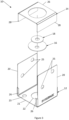
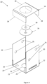
- a post support 10 according to a preferred embodiment of the invention is shown in Figure 1 .
- the post support 10 is configured for securing a post to a ground surface.
- the post support 10 has a base 12 securable to a surface and a cap 14 for concealing fasteners used for securing the base 12 to the surface.
- a large washer 16 is used to allow for adjustment in the position of the post support 10 so that dimensional variances in the position of the post can be accommodated.
- a small washer 18 is provided along with the large washer 16 to increase the effective thickness of the washer 16 and improve uplift or pull-out resistance of the post support.
- the base 12 has two upstanding portions 20 with a central base portion 21.
- the central base portion 21 is receivable against the surface and has a central aperture 22 through which at least one fastener may be received.
- Aperture 22 is larger than an external diameter of the fastener to allow for adjustment of the position of the post support 10, as will be described in further detail below.
- apertures 23 may be used to secure the post support 10 to the surface.
- the two upstanding portions 20 are configured to extend on either side of the post to allow the post to be secured to the post support 10. This may be achieved via the traditional method of using bolts 38 that extend through apertures 25, though a threaded fastener pair 24 as illustrated in Figures 17 to 19 may also be used.
- the threaded fastener pair 24 includes a first fastener 32 with a male threaded portion 33, and a second fastener 34 with a female threaded portion 35.
- the female threaded portion 35 is configured to receive the male threaded portion 33.
- the fasteners are of equal length and length A2 equals length B2. Also, length A1 equals length B1, with B1 being the length of which fastener 34 extends past the midpoint or centreline x between the heads of each fastener.
- the first fastener 32 is formed with a shank 36 having an outer diameter approximately equal to an outer diameter of the second fastener 34.
- the shank 36 of the first threaded fastener 12 is at least 10mm long and has a diameter of at least 10mm.
- the second threaded fastener 34 has a length equal to or greater than that of the first threaded fastener 32 and the length of the first threaded fastener 32 is at least 50mm.
- the first threaded fastener 32 is available in lengths of 50mm, 70mm and 110mm, though it will be appreciated that longer lengths may also be possible.
- first threaded fastener 32 with a shank 36 having an outer diameter that is approximately equal to an outer diameter of the second fastener 34, and the fasteners 32, 34 being of equal length
- an inner bore of a through hole formed in the post is well supported on the fastener pair with the shank 36 and outer diameter of the second fastener contacting the upstanding sides 20.
- a neat connection without exposed ends of threads is provided, without compromising the strength of the connection between the fastener pair 24 and the post support 10.
- Threaded fastener pair 24 is further described in Australian provisional patent application no. 2019901647 , also to the present applicant.
- the cap 14 has a central support portion 26 for supporting an end of a post.
- the central support portion 26 is disposed between two downwardly extending portions 28, that are provided to offset the central support portion 26 from the base 12.
- Large washer 16 is formed from the cap 14 from a punching process, resulting in a central aperture 30 being formed in the cap 14.
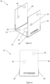
- the cap 14 is receivable within the base 12 and rotatable between a first condition of use ( Figure 3 ) in which the said fasteners are accessible and a second condition of use ( Figure 4 ) in which the fasteners are concealed.
- a first condition of use Figure 3
- a second condition of use Figure 4
- the method of securing the support 10 to a surface will be described in further detail below.
- At least one protuberance is provided, the protuberance being associated with the upstanding portions 20 and the downwardly extending portions 28 for retaining the cap 14 within the base 12.
- the protuberance may take different forms and may extend from either the upstanding portions 20 or the downwardly extending portions 28.
- the protuberance is a pair of tabs 26 formed on the upstanding portions 20 and extending inwardly to engage the downwardly extending portions 28 of the cap 14. As can be seen in Figure 7 , two tabs 26 are provided on either side of the post support 10 (four total) to prevent sideways movement on the cap 14 in the base 12.
- a single post support 10 may be provided which is adaptable between a first condition of use ( Figure 3 ) where fasteners used to secure the post support 10 to the surface are accessible for adjustment after installation, and a second condition of use ( Figure 4 ) where the fasteners are hidden, thereby providing a cleaner, finished look.
- FIGS 13 and 14 illustrate large washer 16, which preferably has an outer diameter which is larger than aperture 22 in the base portion 21.
- washer 16 having an aperture 17 formed therein at a location which is offset from a centre of the washer 16, which would allow that when a fastener is received through the aperture 17 in the washer 16 at least a portion of the washer 16 will always overlap the base portion 21 to ensure retention, in other embodiments the aperture 17 may be centrally disposed.
- the use of washer 16 allows for adjustment in the position of the post support 10 to accommodate a varying location of a post.
- Small washer 18, as illustrated in Figures 15 and 16 is provided to increase the effective thickness of the washer 16 to increase pull out strength.
- Base 12 and cap 14 of the post support 10 may be formed of galvanised steel, though may be formed of other materials.
- the base and cap are formed from a sheet of material, with the tabs being folded inwardly.
- the base 12 may first be positioned on the surface and a position of securing fasteners located. Once the fasteners have been installed, the base 12 is then secured to the surface and cap 14 installed in the desired position, which may be the first condition of use shown in Figure 3 where access to the securing fasteners is provided, or the second condition of use of Figure 4 , where the securing fasteners are hidden.
- a post (40) may then be installed and secured to the post support 10, as shown in Figure 1 .
Landscapes
- Engineering & Computer Science (AREA)
- Architecture (AREA)
- General Engineering & Computer Science (AREA)
- Civil Engineering (AREA)
- Structural Engineering (AREA)
- Mechanical Engineering (AREA)
- Snaps, Bayonet Connections, Set Pins, And Snap Rings (AREA)
- Forms Removed On Construction Sites Or Auxiliary Members Thereof (AREA)
- Connection Of Plates (AREA)
Claims (10)
- Pfostenträger (10) aufweisend eine Basis (12), die an einer Oberfläche befestigt werden kann, und einen Deckel (14) zum Verdecken von Befestigungsmitteln, die zum Befestigen der Basis an der Oberfläche verwendet werden, dadurch gekennzeichnet, dass:die Basis zwei aufrechte Bereiche (20) mit einem zentralen Basisbereich (21) dazwischen aufweist,der Deckel einen zentralen Stützbereich (26) zwischen zwei sich nach unten erstreckenden Bereichen (28) aufweist, wobei der Deckel (14) in der Basis (12) aufgenommen werden kann und zwischen einem ersten Verwendungszustand, in dem die Befestigungsmittel zugänglich sind, und einem zweiten Verwendungszustand, in dem die Befestigungsmittel verdeckt sind, drehbar ist, undmindestens eine Ausstülpung vorgesehen ist, wobei die Ausstülpung mit den aufrechten Bereichen (20) und den sich nach unten erstreckenden Bereichen (28) verbunden ist, um den Deckel in der Basis zu halten.
- Pfostenträger gemäß Anspruch 1, wobei die Ausstülpung ein Paar Laschen (26) ist, die an den aufrechten Bereichen der Basis ausgebildet sind und sich nach innen erstrecken, um mit den sich nach unten erstreckenden Bereichen des Deckels in Eingriff zu kommen.
- Pfostenträger gemäß Anspruch 2, wobei die Basis aus einer Materialplatte ausgebildet ist, wobei die Laschen nach innen gefaltet sind.
- Pfostenträger gemäß einem der vorhergehenden Ansprüche, wobei der zentrale Basisbereich mit einer zentralen Öffnung (22) ausgebildet ist, durch die die Befestigungsmittel aufgenommen werden können.
- Pfostenträger gemäß einem der vorhergehenden Ansprüche, wobei die zentrale Öffnung größer ist als das Befestigungsmittel, damit die Position des Pfostenträgers nach Bedarf eingestellt werden kann.
- Pfostenträger gemäß Anspruch 5, wobei der Pfostenträger ferner eine Unterlegscheibe (16) aufweisend einen Außendurchmesser aufweist, der größer ist als die Öffnung im Basisbereich, so dass mindestens ein Teil der Unterlegscheibe den Basisbereich überlappt.
- Pfostenträgersystem beinhaltend einem Pfostenträger gemäß einem der vorhergehenden Ansprüche und ein Gewindebefestigungspaar (24), wobei das Gewindebefestigungspaar Folgendes beinhaltet:ein erstes Gewindebefestigungsmittel (32) mit einem männlichen Gewindebereich; undein zweites Gewindebefestigungsmittel (34) mit einem weiblichen Gewindebereich, wobei der weibliche Gewindebereich so konfiguriert ist, dass er den männlichen Gewindebereich aufnimmt,wobei das erste Gewindebefestigungsmittel mit einem Schaft (36) ausgebildet ist, der einen Außendurchmesser aufweist, der ungefähr gleich dem Außendurchmesser des zweiten Gewindebereichs ist, das zweite Gewindebefestigungsmittel eine Länge aufweist, die gleich oder größer ist als die des ersten Gewindebefestigungsmittels, und an einer Basis des weiblichen Gewindebereichs eine gewindelose Bohrung ist.
- Verfahren zum Ausbilden eines Pfostenträgers (10), beinhaltend die folgenden Schritte:Ausbilden einer Basis (12) aus einer Materialplatte, wobei die Basis zwei aufrechte Bereiche (20) mit einem zentralen Basisbereich (21) dazwischen aufweist,Ausbilden eines Deckels (14) aus einer Materialplatte, wobei der Deckel einen zentralen Stützbereich (26) zwischen zwei sich nach unten erstreckenden Bereichen (28) aufweist, wobei der Deckel innerhalb der Basis aufgenommen werden kann und zwischen einem ersten Verwendungszustand, in dem die Befestigungsmittel zugänglich sind, und einem zweiten Verwendungszustand, in dem die Befestigungsmittel verdeckt sind, drehbar ist, undAusbilden mindestens einer Ausstülpung an dem Deckel oder der Basis, wobei die mindestens eine Ausstülpung mit den aufrechten Bereichen (20) und den sich nach unten erstreckenden Bereichen (28) verbunden ist, um den Deckel (14) in der Basis (12) zu halten.
- Verfahren zum Ausbilden eines Pfostenträgers gemäß Anspruch 8, wobei die mindestens eine Ausstülpung ein Paar sich nach innen erstreckender Laschen (26) ist, die an den aufrechten Bereichen auf beiden Seiten der Basis ausgebildet sind.
- Verfahren zum Installieren eines Pfostens auf einem Pfostenträger, beinhaltend die folgenden Schritte:Bereitstellen eines Pfostenträgers (10) gemäß einem der Ansprüche 1 bis 6,Befestigen des Pfostenträgers an einer Oberfläche;Installieren des Deckels (14) in der gewünschten Ausrichtung; undBefestigen des Pfostens am Pfostenträger.
Applications Claiming Priority (2)
| Application Number | Priority Date | Filing Date | Title |
|---|---|---|---|
| AU2019902393A AU2019902393A0 (en) | 2019-07-05 | Post Support and related methods | |
| PCT/AU2020/050698 WO2021003524A1 (en) | 2019-07-05 | 2020-07-03 | Post support and related methods |
Publications (4)
| Publication Number | Publication Date |
|---|---|
| EP3994316A1 EP3994316A1 (de) | 2022-05-11 |
| EP3994316A4 EP3994316A4 (de) | 2023-06-28 |
| EP3994316C0 EP3994316C0 (de) | 2024-10-02 |
| EP3994316B1 true EP3994316B1 (de) | 2024-10-02 |
Family
ID=74113810
Family Applications (1)
| Application Number | Title | Priority Date | Filing Date |
|---|---|---|---|
| EP20835989.3A Active EP3994316B1 (de) | 2019-07-05 | 2020-07-03 | Pfostenträger, verfahren zur herstellung dieses pfostenträgers und verfahren zur montage eines pfostens auf diesem pfostenträger |
Country Status (5)
| Country | Link |
|---|---|
| US (1) | US12054960B2 (de) |
| EP (1) | EP3994316B1 (de) |
| AU (1) | AU2020310077B2 (de) |
| CA (1) | CA3145831A1 (de) |
| WO (1) | WO2021003524A1 (de) |
Families Citing this family (1)
| Publication number | Priority date | Publication date | Assignee | Title |
|---|---|---|---|---|
| AU2020276319B2 (en) | 2019-05-14 | 2023-08-17 | Topaz Trading Pty Ltd | Threaded fastener pair, post anchor system and method of securing a post to a post anchor |
Family Cites Families (93)
| Publication number | Priority date | Publication date | Assignee | Title |
|---|---|---|---|---|
| US207871A (en) | 1878-09-10 | Improvement in elastic packings for pistons | ||
| US375350A (en) | 1887-12-27 | Saw-screw | ||
| US1966044A (en) | 1933-06-17 | 1934-07-10 | Charles E S Place | Cap screw or bolt |
| US2136523A (en) | 1937-01-26 | 1938-11-15 | Rosenberg Heyman | Socket head cap screw or like fastener |
| US2283494A (en) | 1940-07-22 | 1942-05-19 | Nat Screw & Mfg Company | Method of making screw and washer assemblies |
| US2511051A (en) | 1946-06-19 | 1950-06-13 | Dzus William | Fastening device |
| US2722259A (en) | 1950-11-01 | 1955-11-01 | Dana C Eckenbeck | Insert nut with ball shaped plate engaging extension |
| US2751806A (en) | 1953-10-12 | 1956-06-26 | Hi Shear Rivet Tool Company | Fastener provided with circumferential fluid sealing ring bonded in recess |
| US2752814A (en) | 1954-06-09 | 1956-07-03 | Joseph A Iaia | Conical headed fastener having annular sealing means positioned in said head |
| US2892650A (en) | 1957-05-20 | 1959-06-30 | Russell Mfg Co | Sealing ring |
| US2982166A (en) | 1958-07-24 | 1961-05-02 | Robert W Hobbs | Fastener head the underlying surface of which has means to smooth the workpiece surface |
| US3252495A (en) | 1959-02-18 | 1966-05-24 | Lamson & Sessions Co | Bolt with a knurled barrel-shaped shank |
| US3175454A (en) | 1963-11-26 | 1965-03-30 | Morse Milton | Threaded sealing devices having o-ring recess of asymmetrical configuration |
| US3299766A (en) | 1964-04-30 | 1967-01-24 | Gould William | Sealing element for fastener devices |
| US3370631A (en) | 1965-05-17 | 1968-02-27 | Diamond Expansion Bolt Co Inc | Wood fastener |
| US3462114A (en) | 1966-11-21 | 1969-08-19 | Walden H O Dell Sr | Lug screw for construction forms |
| US3414304A (en) | 1966-11-22 | 1968-12-03 | Hi Shear Corp | Apparatus for fastening a discontinuous body to another structure and the resulting joint |
| US3459447A (en) | 1966-12-13 | 1969-08-05 | Huck Mfg Co | Flush fastener for panel assembly including soft core material |
| US4033243A (en) * | 1976-01-30 | 1977-07-05 | Textron, Inc. | Container fastener system |
| US4199908A (en) * | 1978-08-01 | 1980-04-29 | Teeters Darrel L | Post base elevator |
| US4310273A (en) | 1979-04-30 | 1982-01-12 | Textron Inc. | Fastener assembly |
| US4490083A (en) | 1980-01-10 | 1984-12-25 | Russell, Burdsall, & Ward Corporation | Sealing capped nut and bolt therefor |
| US4609317A (en) | 1985-06-12 | 1986-09-02 | Huck Manufacturing Company | Fastening system including a pull type fastener for constructing articles such as shipping containers and the like |
| JPH0542252Y2 (de) | 1986-11-11 | 1993-10-25 | ||
| US4924648A (en) * | 1989-03-09 | 1990-05-15 | Simpson Strong-Tie Company, Inc. | Standoff timber base connection |
| US5244001A (en) | 1991-01-04 | 1993-09-14 | Lynch James P | Collapsible canopy framework having captured scissor ends with non-compressive pivots |
| US5290131A (en) | 1991-03-22 | 1994-03-01 | Arne Henriksen | Barbed shank fastener |
| US5275410A (en) | 1992-09-22 | 1994-01-04 | Bellehumeur Alex R | Puck for use on a non-ice surface |
| US5375384A (en) * | 1993-01-22 | 1994-12-27 | Wolfson; Yehuda | Holdown apparatus for a shear wall |
| IT230922Y1 (it) | 1993-04-22 | 1999-07-05 | Roces Srl | Struttura di vite di sicurezza,particolarmente per pattini |
| US5477929A (en) | 1993-12-29 | 1995-12-26 | Malco Products, Inc. | Garden tool |
| DE19603887C2 (de) | 1996-02-03 | 1998-07-02 | Lerch Karl Dieter | Anordnung zum Fixieren eines aus der Schädelkapsel zum Zwecke des operativen Eingriffs herausgetrennten Knochenstücks am verbliebenen Schädelbein |
| WO1997029708A1 (en) | 1996-02-14 | 1997-08-21 | Walter Lorenz Surgical, Inc. | Bone fastener and instrument for insertion thereof |
| US5707373A (en) | 1996-04-26 | 1998-01-13 | Ikonos Corporation | Bone fastener and instrument for insertion thereof |
| US6012763A (en) | 1996-10-03 | 2000-01-11 | Anchor Bolt & Screw Company | Trailer door fastener |
| JP3870329B2 (ja) | 1997-02-25 | 2007-01-17 | 日本機電株式会社 | 鋼管緊結金具 |
| US6039243A (en) | 1997-10-14 | 2000-03-21 | Lickton; Robert J. | Collapsible shipping container |
| US6379363B1 (en) | 1999-09-24 | 2002-04-30 | Walter Lorenz Surgical, Inc. | Method and apparatus for reattachment of a cranial flap using a cranial clamp |
| JP2001227523A (ja) | 2000-02-14 | 2001-08-24 | Hitachi Ltd | 化学薬品処理設備における部材結合装置 |
| US6513290B2 (en) * | 2000-12-03 | 2003-02-04 | Simpson Strong-Tie Company, Inc. | Concentric holdown |
| US6460308B1 (en) | 2001-02-05 | 2002-10-08 | John Armstrong | Foundation bolt rework kit and method of using same |
| US6648518B2 (en) | 2001-02-08 | 2003-11-18 | Gkn Automotive, Inc. | Constant velocity joint assembly with retention member |
| US6685707B2 (en) | 2001-09-25 | 2004-02-03 | Walter Lorenz Surgical, Inc. | Cranial clamp and method for fixating a bone plate |
| US6854921B2 (en) | 2002-07-10 | 2005-02-15 | The Boeing Company | Ballistic resistant cap nut |
| US7329077B2 (en) | 2004-07-01 | 2008-02-12 | Curtis David A W | Fastener apparatus for roofing and steel building construction |
| US20060022189A1 (en) * | 2004-07-30 | 2006-02-02 | Collins Earle S Iv | Fixture and mounting assembly for a fence post |
| SE527767C2 (sv) | 2004-10-22 | 2006-05-30 | Volvo Lastvagnar Ab | Fästelement |
| DE202005008088U1 (de) | 2005-05-19 | 2005-08-18 | Gust. Alberts Gmbh & Co Kg | Abdeckung für Pfostenträger, Bodenhülsen u.dgl. |
| DE202006008339U1 (de) | 2005-05-23 | 2006-10-05 | Müller, Thomas | Bodenhülse |
| US7563063B1 (en) | 2006-02-28 | 2009-07-21 | Steve Madej | Multipurpose fastener kit and associated accessories |
| US8210785B1 (en) | 2006-12-06 | 2012-07-03 | Gager Dennis J | Decorative cap and nut for toilet base |
| USD592097S1 (en) | 2007-12-19 | 2009-05-12 | Androuais James W | Charm belt with removable decorative buttons |
| KR20090007770U (ko) | 2008-01-28 | 2009-07-31 | (주)용신프라임 | 난간의 고정구조 |
| US9033631B2 (en) | 2009-04-17 | 2015-05-19 | United Technologies Corporation | High temperature thread locking compound |
| US10166015B2 (en) | 2010-04-11 | 2019-01-01 | Lapiq, Inc | Implantable scaffold and method |
| CA2746029C (en) * | 2010-07-09 | 2017-04-25 | Richard Bergman | Apparatus and method for replacing a rotted portion of a support post and securing the post to surface or pier |
| US8544196B2 (en) | 2010-08-20 | 2013-10-01 | Susan Leo | Shoe charm holder device |
| US10143269B2 (en) | 2010-08-20 | 2018-12-04 | Susan Leo | Shoe charm holder device |
| US9943137B2 (en) | 2010-08-20 | 2018-04-17 | Susan Leo | Shoe charm holder device |
| US9861163B2 (en) | 2010-08-20 | 2018-01-09 | Susan Leo | Shoe charm holder device |
| JP5498903B2 (ja) | 2010-09-27 | 2014-05-21 | メイラ株式会社 | 雄型締結具 |
| EP2511539A1 (de) | 2011-04-11 | 2012-10-17 | Amec System GmbH | Schraubverbindung |
| US9200590B2 (en) | 2012-03-05 | 2015-12-01 | GM Global Technology Operations LLC | Assembly with composite fastener for attaching components with sealant and method of attaching same |
| US9133874B2 (en) | 2012-06-15 | 2015-09-15 | Oz-Post International, LLC | Mounting hardware |
| US9377047B2 (en) | 2013-06-14 | 2016-06-28 | Oz-Post International, LLC | Through bolted connection hardware |
| US8864096B1 (en) * | 2012-10-04 | 2014-10-21 | Fox Hardwood Lumber Company, L.L.C. | Anchor device for a wooden post |
| US9371738B2 (en) | 2012-12-20 | 2016-06-21 | United Technologies Corporation | Variable outer air seal support |
| US10392228B2 (en) | 2013-03-08 | 2019-08-27 | Harry Miller Co., Llc | Button hook pad hanger |
| US20140263887A1 (en) | 2013-03-13 | 2014-09-18 | Harry Miller Co., Inc. | Elevator pad hanging apparatus and method |
| US9333825B2 (en) | 2013-03-15 | 2016-05-10 | GM Global Technology Operations LLC | Vehicle front suspension lower control arm attachment system |
| US10392234B2 (en) | 2013-05-16 | 2019-08-27 | Axion Structural Innovations, Llc | Nut and a method of use of the nut in a fastener system for crane mats |
| DE102013011655B4 (de) | 2013-07-12 | 2016-10-27 | Knorr-Bremse Systeme für Nutzfahrzeuge GmbH | Bremsbelaghalterung einer Scheibenbremse für ein Nutzfahrzeug |
| US9610490B2 (en) | 2013-10-29 | 2017-04-04 | Dynamic Fitness & Strength, LLC | Weight storage peg for fitness apparatus |
| US8959857B1 (en) * | 2014-01-15 | 2015-02-24 | Simpson Strong-Tie Company | Single-piece standoff post base for retrofit |
| US9976591B2 (en) | 2014-01-31 | 2018-05-22 | Kohler Co. | Bolt and cap assembly for plumbing fixture |
| US9347196B2 (en) * | 2014-02-07 | 2016-05-24 | Bennie R. Wagler | Post-frame footing assembly and vertical post |
| EP3114293B1 (de) * | 2014-03-06 | 2019-04-10 | Betafence Holding | Stützstruktur für einen zaun |
| JP6509325B2 (ja) | 2014-04-25 | 2019-05-08 | ビューラー・アクチエンゲゼルシャフトBuehler AG | 差し込み結合部を備える注入機械 |
| US9377046B1 (en) | 2014-05-15 | 2016-06-28 | Infinite Technologies, Inc. | Fastener assembly |
| US20160069375A1 (en) | 2014-09-10 | 2016-03-10 | Engineered Components Company | Fixed length fastener assembly |
| US9851048B2 (en) | 2015-03-27 | 2017-12-26 | Altec Industries, Inc. | Liner retention system for an aerial device |
| EP3124362B1 (de) | 2015-07-29 | 2017-12-13 | Autotech Engineering Deutschland GmbH | Hilfsrahmen, insbesondere hinterachshilfsrahmen, für ein personenkraftfahrzeug |
| US9759510B1 (en) | 2016-03-09 | 2017-09-12 | James J. Kempf | Vibration dampening limb bolt |
| DE202017105045U1 (de) | 2016-10-07 | 2017-12-07 | Jing-Xin Solar Ltd. | Bodenhalterung |
| KR101879282B1 (ko) | 2016-11-16 | 2018-07-18 | (주)신흥정밀 | 커버 열림 검출 회로를 갖는 pci 단말기 |
| US10677566B2 (en) | 2016-12-13 | 2020-06-09 | Stone Protective Solutions, Llc | Blast panel assembly |
| FR3063121B1 (fr) | 2017-02-22 | 2019-03-29 | Bollhoff Otalu S.A. | Insert a sertir, element et ensemble de fixation comprenant un tel insert et procedes de fabrication de telles pieces. |
| TWM572937U (zh) | 2018-03-28 | 2019-01-11 | 世豐螺絲股份有限公司 | Screw with irregular embossing pattern |
| USD905547S1 (en) | 2019-04-03 | 2020-12-22 | The Campion Innovation Company Pty Ltd | Screw head cap |
| USD897830S1 (en) | 2019-04-29 | 2020-10-06 | Gestion Roberto Inc. | Nut for stud removal device |
| AU2020276319B2 (en) | 2019-05-14 | 2023-08-17 | Topaz Trading Pty Ltd | Threaded fastener pair, post anchor system and method of securing a post to a post anchor |
| US11028969B2 (en) | 2019-06-03 | 2021-06-08 | The Boeing Company | Structural interface hardware for cryogenic tanks |
| US11649951B1 (en) | 2021-12-02 | 2023-05-16 | Tractor Supply Company | Manufacturing of light emitting modules |
-
2020
- 2020-07-03 EP EP20835989.3A patent/EP3994316B1/de active Active
- 2020-07-03 AU AU2020310077A patent/AU2020310077B2/en active Active
- 2020-07-03 US US17/624,988 patent/US12054960B2/en active Active
- 2020-07-03 WO PCT/AU2020/050698 patent/WO2021003524A1/en not_active Ceased
- 2020-07-03 CA CA3145831A patent/CA3145831A1/en active Pending
Also Published As
| Publication number | Publication date |
|---|---|
| US20220259884A1 (en) | 2022-08-18 |
| US12054960B2 (en) | 2024-08-06 |
| EP3994316A4 (de) | 2023-06-28 |
| WO2021003524A1 (en) | 2021-01-14 |
| EP3994316C0 (de) | 2024-10-02 |
| AU2020310077B2 (en) | 2026-04-16 |
| AU2020310077A1 (en) | 2022-02-17 |
| CA3145831A1 (en) | 2021-01-14 |
| EP3994316A1 (de) | 2022-05-11 |
Similar Documents
| Publication | Publication Date | Title |
|---|---|---|
| US11028580B2 (en) | Deck frame with integral attachment tabs | |
| CA2961478C (en) | Adjustable deck tension tie | |
| WO2004007874A1 (en) | Pole cover or sleeve | |
| CA2907941C (en) | Attachment element | |
| EP3994316B1 (de) | Pfostenträger, verfahren zur herstellung dieses pfostenträgers und verfahren zur montage eines pfostens auf diesem pfostenträger | |
| EP3944490B1 (de) | Haltevorrichtung zum lösbaren befestigen eines solarmoduls | |
| EP0827562A1 (de) | Verbesserungungen in und in verband mit einer befestigung | |
| CA2688703A1 (en) | Alignment pin for aesthetic cover assembly and method | |
| US20180106420A1 (en) | Mounting system and method | |
| WO2008127796A1 (en) | Cage nut fastening system | |
| US4603840A (en) | Fence support member | |
| US20110042528A1 (en) | Interface adapter connector for effectively connecting a seismic sway brace or restraint pipe to a support anchor | |
| JP3140137U (ja) | 杭打ち設置用具 | |
| JP4201896B2 (ja) | 防護柵の支柱とビームパイプのボルト止め構造 | |
| JP2011196142A (ja) | 防護柵のビーム取付構造 | |
| US6749359B1 (en) | Seismic suspension system | |
| US6217270B1 (en) | Bracing rod washer assembly and clamping washer | |
| JP3034009U (ja) | Uボルト式締結具 | |
| JP7623695B2 (ja) | ワイヤーロープ締結金具 | |
| KR101604190B1 (ko) | 유연성 가로부재를 이용한 가설판넬 및 그 시공 방법 | |
| KR200185085Y1 (ko) | 포스트형 옷걸이 | |
| US20070199666A1 (en) | Support System | |
| EP0813278B1 (de) | Als Blechformteil hergestellte Kopfplatte | |
| US20020060083A1 (en) | Grounding device | |
| AU2016336026B2 (en) | Fence post brace |
Legal Events
| Date | Code | Title | Description |
|---|---|---|---|
| STAA | Information on the status of an ep patent application or granted ep patent |
Free format text: STATUS: THE INTERNATIONAL PUBLICATION HAS BEEN MADE |
|
| PUAI | Public reference made under article 153(3) epc to a published international application that has entered the european phase |
Free format text: ORIGINAL CODE: 0009012 |
|
| STAA | Information on the status of an ep patent application or granted ep patent |
Free format text: STATUS: REQUEST FOR EXAMINATION WAS MADE |
|
| 17P | Request for examination filed |
Effective date: 20220124 |
|
| AK | Designated contracting states |
Kind code of ref document: A1 Designated state(s): AL AT BE BG CH CY CZ DE DK EE ES FI FR GB GR HR HU IE IS IT LI LT LU LV MC MK MT NL NO PL PT RO RS SE SI SK SM TR |
|
| DAV | Request for validation of the european patent (deleted) | ||
| DAX | Request for extension of the european patent (deleted) | ||
| A4 | Supplementary search report drawn up and despatched |
Effective date: 20230525 |
|
| RIC1 | Information provided on ipc code assigned before grant |
Ipc: F16B 41/00 20060101ALI20230519BHEP Ipc: F16B 9/02 20060101ALI20230519BHEP Ipc: E01F 9/60 20160101ALI20230519BHEP Ipc: F16B 37/00 20060101ALI20230519BHEP Ipc: E04H 12/22 20060101ALI20230519BHEP Ipc: E04B 1/24 20060101AFI20230519BHEP |
|
| GRAP | Despatch of communication of intention to grant a patent |
Free format text: ORIGINAL CODE: EPIDOSNIGR1 |
|
| STAA | Information on the status of an ep patent application or granted ep patent |
Free format text: STATUS: GRANT OF PATENT IS INTENDED |
|
| RIC1 | Information provided on ipc code assigned before grant |
Ipc: F16B 41/00 20060101ALI20240422BHEP Ipc: F16B 9/02 20060101ALI20240422BHEP Ipc: E01F 9/60 20160101ALI20240422BHEP Ipc: F16B 37/00 20060101ALI20240422BHEP Ipc: E04H 12/22 20060101ALI20240422BHEP Ipc: E04B 1/24 20060101AFI20240422BHEP |
|
| INTG | Intention to grant announced |
Effective date: 20240510 |
|
| GRAS | Grant fee paid |
Free format text: ORIGINAL CODE: EPIDOSNIGR3 |
|
| GRAA | (expected) grant |
Free format text: ORIGINAL CODE: 0009210 |
|
| STAA | Information on the status of an ep patent application or granted ep patent |
Free format text: STATUS: THE PATENT HAS BEEN GRANTED |
|
| AK | Designated contracting states |
Kind code of ref document: B1 Designated state(s): AL AT BE BG CH CY CZ DE DK EE ES FI FR GB GR HR HU IE IS IT LI LT LU LV MC MK MT NL NO PL PT RO RS SE SI SK SM TR |
|
| REG | Reference to a national code |
Ref country code: GB Ref legal event code: FG4D |
|
| REG | Reference to a national code |
Ref country code: CH Ref legal event code: EP |
|
| REG | Reference to a national code |
Ref country code: DE Ref legal event code: R096 Ref document number: 602020038794 Country of ref document: DE |
|
| REG | Reference to a national code |
Ref country code: IE Ref legal event code: FG4D |
|
| U01 | Request for unitary effect filed |
Effective date: 20241101 |
|
| U07 | Unitary effect registered |
Designated state(s): AT BE BG DE DK EE FI FR IT LT LU LV MT NL PT RO SE SI Effective date: 20241112 |
|
| PG25 | Lapsed in a contracting state [announced via postgrant information from national office to epo] |
Ref country code: IS Free format text: LAPSE BECAUSE OF FAILURE TO SUBMIT A TRANSLATION OF THE DESCRIPTION OR TO PAY THE FEE WITHIN THE PRESCRIBED TIME-LIMIT Effective date: 20250202 Ref country code: HR Free format text: LAPSE BECAUSE OF FAILURE TO SUBMIT A TRANSLATION OF THE DESCRIPTION OR TO PAY THE FEE WITHIN THE PRESCRIBED TIME-LIMIT Effective date: 20241002 |
|
| PG25 | Lapsed in a contracting state [announced via postgrant information from national office to epo] |
Ref country code: ES Free format text: LAPSE BECAUSE OF FAILURE TO SUBMIT A TRANSLATION OF THE DESCRIPTION OR TO PAY THE FEE WITHIN THE PRESCRIBED TIME-LIMIT Effective date: 20241002 |
|
| PG25 | Lapsed in a contracting state [announced via postgrant information from national office to epo] |
Ref country code: NO Free format text: LAPSE BECAUSE OF FAILURE TO SUBMIT A TRANSLATION OF THE DESCRIPTION OR TO PAY THE FEE WITHIN THE PRESCRIBED TIME-LIMIT Effective date: 20250102 |
|
| PG25 | Lapsed in a contracting state [announced via postgrant information from national office to epo] |
Ref country code: GR Free format text: LAPSE BECAUSE OF FAILURE TO SUBMIT A TRANSLATION OF THE DESCRIPTION OR TO PAY THE FEE WITHIN THE PRESCRIBED TIME-LIMIT Effective date: 20250103 |
|
| PG25 | Lapsed in a contracting state [announced via postgrant information from national office to epo] |
Ref country code: PL Free format text: LAPSE BECAUSE OF FAILURE TO SUBMIT A TRANSLATION OF THE DESCRIPTION OR TO PAY THE FEE WITHIN THE PRESCRIBED TIME-LIMIT Effective date: 20241002 Ref country code: CZ Free format text: LAPSE BECAUSE OF FAILURE TO SUBMIT A TRANSLATION OF THE DESCRIPTION OR TO PAY THE FEE WITHIN THE PRESCRIBED TIME-LIMIT Effective date: 20241002 |
|
| PG25 | Lapsed in a contracting state [announced via postgrant information from national office to epo] |
Ref country code: RS Free format text: LAPSE BECAUSE OF FAILURE TO SUBMIT A TRANSLATION OF THE DESCRIPTION OR TO PAY THE FEE WITHIN THE PRESCRIBED TIME-LIMIT Effective date: 20250102 |
|
| PG25 | Lapsed in a contracting state [announced via postgrant information from national office to epo] |
Ref country code: SM Free format text: LAPSE BECAUSE OF FAILURE TO SUBMIT A TRANSLATION OF THE DESCRIPTION OR TO PAY THE FEE WITHIN THE PRESCRIBED TIME-LIMIT Effective date: 20241002 |
|
| PG25 | Lapsed in a contracting state [announced via postgrant information from national office to epo] |
Ref country code: SK Free format text: LAPSE BECAUSE OF FAILURE TO SUBMIT A TRANSLATION OF THE DESCRIPTION OR TO PAY THE FEE WITHIN THE PRESCRIBED TIME-LIMIT Effective date: 20241002 |
|
| PLBE | No opposition filed within time limit |
Free format text: ORIGINAL CODE: 0009261 |
|
| STAA | Information on the status of an ep patent application or granted ep patent |
Free format text: STATUS: NO OPPOSITION FILED WITHIN TIME LIMIT |
|
| U20 | Renewal fee for the european patent with unitary effect paid |
Year of fee payment: 6 Effective date: 20250728 |
|
| 26N | No opposition filed |
Effective date: 20250703 |
|
| PGFP | Annual fee paid to national office [announced via postgrant information from national office to epo] |
Ref country code: GB Payment date: 20250722 Year of fee payment: 6 |
|
| PGFP | Annual fee paid to national office [announced via postgrant information from national office to epo] |
Ref country code: IE Payment date: 20250723 Year of fee payment: 6 |
|
| REG | Reference to a national code |
Ref country code: CH Ref legal event code: H13 Free format text: ST27 STATUS EVENT CODE: U-0-0-H10-H13 (AS PROVIDED BY THE NATIONAL OFFICE) Effective date: 20260224 |
|
| PG25 | Lapsed in a contracting state [announced via postgrant information from national office to epo] |
Ref country code: CH Free format text: LAPSE BECAUSE OF NON-PAYMENT OF DUE FEES Effective date: 20250731 |