EP3994319B1 - Élément de plancher pour former un revêtement de plancher et revêtement de plancher - Google Patents
Élément de plancher pour former un revêtement de plancher et revêtement de plancher Download PDFInfo
- Publication number
- EP3994319B1 EP3994319B1 EP20835518.0A EP20835518A EP3994319B1 EP 3994319 B1 EP3994319 B1 EP 3994319B1 EP 20835518 A EP20835518 A EP 20835518A EP 3994319 B1 EP3994319 B1 EP 3994319B1
- Authority
- EP
- European Patent Office
- Prior art keywords
- decorative layer
- floor
- layer
- resin
- floor element
- Prior art date
- Legal status (The legal status is an assumption and is not a legal conclusion. Google has not performed a legal analysis and makes no representation as to the accuracy of the status listed.)
- Active
Links
Images


Classifications
-
- E—FIXED CONSTRUCTIONS
- E04—BUILDING
- E04F—FINISHING WORK ON BUILDINGS, e.g. STAIRS, FLOORS
- E04F15/00—Flooring
- E04F15/02—Flooring or floor layers composed of a number of similar elements
- E04F15/08—Flooring or floor layers composed of a number of similar elements only of stone or stone-like material, e.g. ceramics, concrete; of glass or with a top layer of stone or stone-like material, e.g. ceramics, concrete or glass
- E04F15/082—Flooring or floor layers composed of a number of similar elements only of stone or stone-like material, e.g. ceramics, concrete; of glass or with a top layer of stone or stone-like material, e.g. ceramics, concrete or glass with a top layer of stone or stone-like material, e.g. ceramics, concrete or glass in combination with a lower layer of other material
- E04F15/087—The lower layer being of organic plastic with or without reinforcements or filling materials
-
- B—PERFORMING OPERATIONS; TRANSPORTING
- B32—LAYERED PRODUCTS
- B32B—LAYERED PRODUCTS, i.e. PRODUCTS BUILT-UP OF STRATA OF FLAT OR NON-FLAT, e.g. CELLULAR OR HONEYCOMB, FORM
- B32B27/00—Layered products comprising a layer of synthetic resin
- B32B27/06—Layered products comprising a layer of synthetic resin as the main or only constituent of a layer, which is next to another layer of the same or of a different material
-
- B—PERFORMING OPERATIONS; TRANSPORTING
- B32—LAYERED PRODUCTS
- B32B—LAYERED PRODUCTS, i.e. PRODUCTS BUILT-UP OF STRATA OF FLAT OR NON-FLAT, e.g. CELLULAR OR HONEYCOMB, FORM
- B32B27/00—Layered products comprising a layer of synthetic resin
- B32B27/30—Layered products comprising a layer of synthetic resin comprising vinyl (co)polymers; comprising acrylic (co)polymers
- B32B27/304—Layered products comprising a layer of synthetic resin comprising vinyl (co)polymers; comprising acrylic (co)polymers comprising vinyl halide (co)polymers, e.g. PVC, PVDC, PVF, PVDF
-
- B—PERFORMING OPERATIONS; TRANSPORTING
- B32—LAYERED PRODUCTS
- B32B—LAYERED PRODUCTS, i.e. PRODUCTS BUILT-UP OF STRATA OF FLAT OR NON-FLAT, e.g. CELLULAR OR HONEYCOMB, FORM
- B32B3/00—Layered products comprising a layer with external or internal discontinuities or unevennesses, or a layer of non-planar shape; Layered products comprising a layer having particular features of form
- B32B3/02—Layered products comprising a layer with external or internal discontinuities or unevennesses, or a layer of non-planar shape; Layered products comprising a layer having particular features of form characterised by features of form at particular places, e.g. in edge regions
- B32B3/06—Layered products comprising a layer with external or internal discontinuities or unevennesses, or a layer of non-planar shape; Layered products comprising a layer having particular features of form characterised by features of form at particular places, e.g. in edge regions for securing layers together; for attaching the product to another member, e.g. to a support, or to another product, e.g. groove/tongue, interlocking
-
- B—PERFORMING OPERATIONS; TRANSPORTING
- B32—LAYERED PRODUCTS
- B32B—LAYERED PRODUCTS, i.e. PRODUCTS BUILT-UP OF STRATA OF FLAT OR NON-FLAT, e.g. CELLULAR OR HONEYCOMB, FORM
- B32B33/00—Layered products characterised by particular properties or particular surface features, e.g. particular surface coatings; Layered products designed for particular purposes not covered by another single class
-
- B—PERFORMING OPERATIONS; TRANSPORTING
- B32—LAYERED PRODUCTS
- B32B—LAYERED PRODUCTS, i.e. PRODUCTS BUILT-UP OF STRATA OF FLAT OR NON-FLAT, e.g. CELLULAR OR HONEYCOMB, FORM
- B32B37/00—Methods or apparatus for laminating, e.g. by curing or by ultrasonic bonding
- B32B37/10—Methods or apparatus for laminating, e.g. by curing or by ultrasonic bonding characterised by the pressing technique, e.g. using action of vacuum or fluid pressure
-
- B—PERFORMING OPERATIONS; TRANSPORTING
- B32—LAYERED PRODUCTS
- B32B—LAYERED PRODUCTS, i.e. PRODUCTS BUILT-UP OF STRATA OF FLAT OR NON-FLAT, e.g. CELLULAR OR HONEYCOMB, FORM
- B32B37/00—Methods or apparatus for laminating, e.g. by curing or by ultrasonic bonding
- B32B37/12—Methods or apparatus for laminating, e.g. by curing or by ultrasonic bonding characterised by using adhesives
-
- B—PERFORMING OPERATIONS; TRANSPORTING
- B32—LAYERED PRODUCTS
- B32B—LAYERED PRODUCTS, i.e. PRODUCTS BUILT-UP OF STRATA OF FLAT OR NON-FLAT, e.g. CELLULAR OR HONEYCOMB, FORM
- B32B38/00—Ancillary operations in connection with laminating processes
- B32B38/08—Impregnating
-
- B—PERFORMING OPERATIONS; TRANSPORTING
- B32—LAYERED PRODUCTS
- B32B—LAYERED PRODUCTS, i.e. PRODUCTS BUILT-UP OF STRATA OF FLAT OR NON-FLAT, e.g. CELLULAR OR HONEYCOMB, FORM
- B32B7/00—Layered products characterised by the relation between layers; Layered products characterised by the relative orientation of features between layers, or by the relative values of a measurable parameter between layers, i.e. products comprising layers having different physical, chemical or physicochemical properties; Layered products characterised by the interconnection of layers
- B32B7/04—Interconnection of layers
- B32B7/12—Interconnection of layers using interposed adhesives or interposed materials with bonding properties
-
- B—PERFORMING OPERATIONS; TRANSPORTING
- B32—LAYERED PRODUCTS
- B32B—LAYERED PRODUCTS, i.e. PRODUCTS BUILT-UP OF STRATA OF FLAT OR NON-FLAT, e.g. CELLULAR OR HONEYCOMB, FORM
- B32B9/00—Layered products comprising a layer of a particular substance not covered by groups B32B11/00 - B32B29/00
- B32B9/005—Layered products comprising a layer of a particular substance not covered by groups B32B11/00 - B32B29/00 comprising one layer of ceramic material, e.g. porcelain, ceramic tile
-
- B—PERFORMING OPERATIONS; TRANSPORTING
- B32—LAYERED PRODUCTS
- B32B—LAYERED PRODUCTS, i.e. PRODUCTS BUILT-UP OF STRATA OF FLAT OR NON-FLAT, e.g. CELLULAR OR HONEYCOMB, FORM
- B32B9/00—Layered products comprising a layer of a particular substance not covered by groups B32B11/00 - B32B29/00
- B32B9/04—Layered products comprising a layer of a particular substance not covered by groups B32B11/00 - B32B29/00 comprising such particular substance as the main or only constituent of a layer, which is next to another layer of the same or of a different material
- B32B9/045—Layered products comprising a layer of a particular substance not covered by groups B32B11/00 - B32B29/00 comprising such particular substance as the main or only constituent of a layer, which is next to another layer of the same or of a different material of synthetic resin
-
- E—FIXED CONSTRUCTIONS
- E04—BUILDING
- E04F—FINISHING WORK ON BUILDINGS, e.g. STAIRS, FLOORS
- E04F15/00—Flooring
- E04F15/02—Flooring or floor layers composed of a number of similar elements
- E04F15/02038—Flooring or floor layers composed of a number of similar elements characterised by tongue and groove connections between neighbouring flooring elements
-
- E—FIXED CONSTRUCTIONS
- E04—BUILDING
- E04F—FINISHING WORK ON BUILDINGS, e.g. STAIRS, FLOORS
- E04F15/00—Flooring
- E04F15/02—Flooring or floor layers composed of a number of similar elements
- E04F15/0215—Flooring or floor layers composed of a number of similar elements specially adapted for being adhesively fixed to an underlayer; Fastening means therefor; Fixing by means of plastics materials hardening after application
-
- E—FIXED CONSTRUCTIONS
- E04—BUILDING
- E04F—FINISHING WORK ON BUILDINGS, e.g. STAIRS, FLOORS
- E04F15/00—Flooring
- E04F15/02—Flooring or floor layers composed of a number of similar elements
- E04F15/08—Flooring or floor layers composed of a number of similar elements only of stone or stone-like material, e.g. ceramics, concrete; of glass or with a top layer of stone or stone-like material, e.g. ceramics, concrete or glass
- E04F15/082—Flooring or floor layers composed of a number of similar elements only of stone or stone-like material, e.g. ceramics, concrete; of glass or with a top layer of stone or stone-like material, e.g. ceramics, concrete or glass with a top layer of stone or stone-like material, e.g. ceramics, concrete or glass in combination with a lower layer of other material
-
- E—FIXED CONSTRUCTIONS
- E04—BUILDING
- E04F—FINISHING WORK ON BUILDINGS, e.g. STAIRS, FLOORS
- E04F15/00—Flooring
- E04F15/02—Flooring or floor layers composed of a number of similar elements
- E04F15/10—Flooring or floor layers composed of a number of similar elements of other materials, e.g. fibrous or chipped materials, organic plastics, magnesite tiles, hardboard, or with a top layer of other materials
- E04F15/107—Flooring or floor layers composed of a number of similar elements of other materials, e.g. fibrous or chipped materials, organic plastics, magnesite tiles, hardboard, or with a top layer of other materials composed of several layers, e.g. sandwich panels
-
- B—PERFORMING OPERATIONS; TRANSPORTING
- B32—LAYERED PRODUCTS
- B32B—LAYERED PRODUCTS, i.e. PRODUCTS BUILT-UP OF STRATA OF FLAT OR NON-FLAT, e.g. CELLULAR OR HONEYCOMB, FORM
- B32B2250/00—Layers arrangement
- B32B2250/02—2 layers
-
- B—PERFORMING OPERATIONS; TRANSPORTING
- B32—LAYERED PRODUCTS
- B32B—LAYERED PRODUCTS, i.e. PRODUCTS BUILT-UP OF STRATA OF FLAT OR NON-FLAT, e.g. CELLULAR OR HONEYCOMB, FORM
- B32B2255/00—Coating on the layer surface
-
- B—PERFORMING OPERATIONS; TRANSPORTING
- B32—LAYERED PRODUCTS
- B32B—LAYERED PRODUCTS, i.e. PRODUCTS BUILT-UP OF STRATA OF FLAT OR NON-FLAT, e.g. CELLULAR OR HONEYCOMB, FORM
- B32B2255/00—Coating on the layer surface
- B32B2255/26—Polymeric coating
-
- B—PERFORMING OPERATIONS; TRANSPORTING
- B32—LAYERED PRODUCTS
- B32B—LAYERED PRODUCTS, i.e. PRODUCTS BUILT-UP OF STRATA OF FLAT OR NON-FLAT, e.g. CELLULAR OR HONEYCOMB, FORM
- B32B2260/00—Layered product comprising an impregnated, embedded, or bonded layer wherein the layer comprises an impregnation, embedding, or binder material
- B32B2260/02—Composition of the impregnated, bonded or embedded layer
-
- B—PERFORMING OPERATIONS; TRANSPORTING
- B32—LAYERED PRODUCTS
- B32B—LAYERED PRODUCTS, i.e. PRODUCTS BUILT-UP OF STRATA OF FLAT OR NON-FLAT, e.g. CELLULAR OR HONEYCOMB, FORM
- B32B2260/00—Layered product comprising an impregnated, embedded, or bonded layer wherein the layer comprises an impregnation, embedding, or binder material
- B32B2260/04—Impregnation, embedding, or binder material
- B32B2260/046—Synthetic resin
-
- B—PERFORMING OPERATIONS; TRANSPORTING
- B32—LAYERED PRODUCTS
- B32B—LAYERED PRODUCTS, i.e. PRODUCTS BUILT-UP OF STRATA OF FLAT OR NON-FLAT, e.g. CELLULAR OR HONEYCOMB, FORM
- B32B2307/00—Properties of the layers or laminate
- B32B2307/40—Properties of the layers or laminate having particular optical properties
- B32B2307/402—Coloured
-
- B—PERFORMING OPERATIONS; TRANSPORTING
- B32—LAYERED PRODUCTS
- B32B—LAYERED PRODUCTS, i.e. PRODUCTS BUILT-UP OF STRATA OF FLAT OR NON-FLAT, e.g. CELLULAR OR HONEYCOMB, FORM
- B32B2307/00—Properties of the layers or laminate
- B32B2307/50—Properties of the layers or laminate having particular mechanical properties
- B32B2307/546—Flexural strength; Flexion stiffness
-
- B—PERFORMING OPERATIONS; TRANSPORTING
- B32—LAYERED PRODUCTS
- B32B—LAYERED PRODUCTS, i.e. PRODUCTS BUILT-UP OF STRATA OF FLAT OR NON-FLAT, e.g. CELLULAR OR HONEYCOMB, FORM
- B32B2307/00—Properties of the layers or laminate
- B32B2307/50—Properties of the layers or laminate having particular mechanical properties
- B32B2307/558—Impact strength, toughness
-
- B—PERFORMING OPERATIONS; TRANSPORTING
- B32—LAYERED PRODUCTS
- B32B—LAYERED PRODUCTS, i.e. PRODUCTS BUILT-UP OF STRATA OF FLAT OR NON-FLAT, e.g. CELLULAR OR HONEYCOMB, FORM
- B32B2307/00—Properties of the layers or laminate
- B32B2307/70—Other properties
- B32B2307/718—Weight, e.g. weight per square meter
-
- B—PERFORMING OPERATIONS; TRANSPORTING
- B32—LAYERED PRODUCTS
- B32B—LAYERED PRODUCTS, i.e. PRODUCTS BUILT-UP OF STRATA OF FLAT OR NON-FLAT, e.g. CELLULAR OR HONEYCOMB, FORM
- B32B2307/00—Properties of the layers or laminate
- B32B2307/70—Other properties
- B32B2307/732—Dimensional properties
-
- B—PERFORMING OPERATIONS; TRANSPORTING
- B32—LAYERED PRODUCTS
- B32B—LAYERED PRODUCTS, i.e. PRODUCTS BUILT-UP OF STRATA OF FLAT OR NON-FLAT, e.g. CELLULAR OR HONEYCOMB, FORM
- B32B2309/00—Parameters for the laminating or treatment process; Apparatus details
- B32B2309/04—Time
-
- B—PERFORMING OPERATIONS; TRANSPORTING
- B32—LAYERED PRODUCTS
- B32B—LAYERED PRODUCTS, i.e. PRODUCTS BUILT-UP OF STRATA OF FLAT OR NON-FLAT, e.g. CELLULAR OR HONEYCOMB, FORM
- B32B2309/00—Parameters for the laminating or treatment process; Apparatus details
- B32B2309/12—Pressure
-
- B—PERFORMING OPERATIONS; TRANSPORTING
- B32—LAYERED PRODUCTS
- B32B—LAYERED PRODUCTS, i.e. PRODUCTS BUILT-UP OF STRATA OF FLAT OR NON-FLAT, e.g. CELLULAR OR HONEYCOMB, FORM
- B32B2315/00—Other materials containing non-metallic inorganic compounds not provided for in groups B32B2311/00 - B32B2313/04
- B32B2315/02—Ceramics
-
- B—PERFORMING OPERATIONS; TRANSPORTING
- B32—LAYERED PRODUCTS
- B32B—LAYERED PRODUCTS, i.e. PRODUCTS BUILT-UP OF STRATA OF FLAT OR NON-FLAT, e.g. CELLULAR OR HONEYCOMB, FORM
- B32B2327/00—Polyvinylhalogenides
- B32B2327/06—PVC, i.e. polyvinylchloride
-
- B—PERFORMING OPERATIONS; TRANSPORTING
- B32—LAYERED PRODUCTS
- B32B—LAYERED PRODUCTS, i.e. PRODUCTS BUILT-UP OF STRATA OF FLAT OR NON-FLAT, e.g. CELLULAR OR HONEYCOMB, FORM
- B32B2451/00—Decorative or ornamental articles
-
- B—PERFORMING OPERATIONS; TRANSPORTING
- B32—LAYERED PRODUCTS
- B32B—LAYERED PRODUCTS, i.e. PRODUCTS BUILT-UP OF STRATA OF FLAT OR NON-FLAT, e.g. CELLULAR OR HONEYCOMB, FORM
- B32B2471/00—Floor coverings
-
- E—FIXED CONSTRUCTIONS
- E04—BUILDING
- E04F—FINISHING WORK ON BUILDINGS, e.g. STAIRS, FLOORS
- E04F2201/00—Joining sheets or plates or panels
- E04F2201/01—Joining sheets, plates or panels with edges in abutting relationship
- E04F2201/0138—Joining sheets, plates or panels with edges in abutting relationship by moving the sheets, plates or panels perpendicular to the main plane
- E04F2201/0146—Joining sheets, plates or panels with edges in abutting relationship by moving the sheets, plates or panels perpendicular to the main plane with snap action of the edge connectors
-
- E—FIXED CONSTRUCTIONS
- E04—BUILDING
- E04F—FINISHING WORK ON BUILDINGS, e.g. STAIRS, FLOORS
- E04F2201/00—Joining sheets or plates or panels
- E04F2201/01—Joining sheets, plates or panels with edges in abutting relationship
- E04F2201/0153—Joining sheets, plates or panels with edges in abutting relationship by rotating the sheets, plates or panels around an axis which is parallel to the abutting edges, possibly combined with a sliding movement
-
- E—FIXED CONSTRUCTIONS
- E04—BUILDING
- E04F—FINISHING WORK ON BUILDINGS, e.g. STAIRS, FLOORS
- E04F2201/00—Joining sheets or plates or panels
- E04F2201/02—Non-undercut connections, e.g. tongue and groove connections
- E04F2201/023—Non-undercut connections, e.g. tongue and groove connections with a continuous tongue or groove
-
- E—FIXED CONSTRUCTIONS
- E04—BUILDING
- E04F—FINISHING WORK ON BUILDINGS, e.g. STAIRS, FLOORS
- E04F2201/00—Joining sheets or plates or panels
- E04F2201/03—Undercut connections, e.g. using undercut tongues or grooves
-
- E—FIXED CONSTRUCTIONS
- E04—BUILDING
- E04F—FINISHING WORK ON BUILDINGS, e.g. STAIRS, FLOORS
- E04F2201/00—Joining sheets or plates or panels
- E04F2201/04—Other details of tongues or grooves
- E04F2201/042—Other details of tongues or grooves with grooves positioned on the rear-side of the panel
-
- E—FIXED CONSTRUCTIONS
- E04—BUILDING
- E04F—FINISHING WORK ON BUILDINGS, e.g. STAIRS, FLOORS
- E04F2201/00—Joining sheets or plates or panels
- E04F2201/04—Other details of tongues or grooves
- E04F2201/043—Other details of tongues or grooves with tongues and grooves being formed by projecting or recessed parts of the panel layers
Definitions
- the present invention relates to a floor element for forming a floor covering, a floor covering, and a method for manufacturing a floor element.
- the invention is related to a floor element for forming a floor covering, wherein this floor element comprises a decorative layer made of a brittle material such as natural stone, glass or sintered ceramic materials like porcelain, earthenware or the like.
- the decorative layer can, for example, be a ceramic tile.
- ceramic tiles are installed by laying them side by side on a surface such as a floor or wall.
- an adhesive compound is used to attach the tiles to the surface. Seams between the tiles are grouted.
- the tiles are bonded to a rigid surface, for example a concrete subfloor, thereby improving their impact strength.
- the bound with the subfloor, and thus also with the structure of the dwelling, also leads to a high attenuation of walking sounds, both in the room where the floor is installed, and in quarters below the respective room.
- the tiled surface is water impervious and hygienic, since it can be cleaned in a very wet manner.
- WO 2004/097141 and WO 2008/097860 The floor elements disclosed in those documents can be laid on a surface and mechanically coupled together to form a floor covering without the use of an adhesive, thereby reducing the labor and time of the installing phase.
- Such kind of floor covering is known as a floating floor covering.
- a ceramic tile or natural stone slab is fixed to a support layer that comprises coupling elements configured to realize a coupling with coupling elements of an adjacent floor element, thereby forming a floor covering.
- US 2014/349084 suggests a tile with a composite build-up.
- a reinforcing layer is arranged in between two ceramic layers or in between a ceramic layer and a polymer laminate.
- a fiberglass layer is mentioned.
- the installation of this tile is, however, still cumbersome.
- a bonding with an underlying subfloor is required, for example via a bottom layer with pressure sensitive adhesive or tack fast loop fabric so that the tile is substantially made solid with the subfloor for improving the impact strength.
- a precise positioning of the tile is difficult.
- WO 2010/072704 proposes a different type of reinforcing layer, namely a steel plate.
- This steel plate is adhered to the back surface of the ceramic tile or slab.
- the installation is, however, difficult. The installation is done by simply resting the tiles on a subfloor, so that a precise positioning of the tile is difficult and the floor covering results in a not well levelled surface and in a noisy and permeable floor covering.
- CA 2 523 866 A1 discloses a floor element according to the preamble of claim 1.
- the present invention provides a floor covering comprising a plurality of floor elements as described herein.
- Another aspect not part of the present invention provides a method for manufacturing a floor element comprising the steps of: providing a decorative layer made of a ceramic material; providing a support layer; providing a resin material for bonding the decorative layer and the support layer together; and pressing the decorative layer and the support layer together to form the floor element such that the resin material permeates the decorative layer.
- Another aspect not part of the present invention provides the use of a resin material for bonding together a decorative layer made of a ceramic material and a support layer to form a floor element, the resin material having a viscosity less than 1000 mPas at 20°C.
- a floor element comprising: a decorative layer having density as expressed by surface weight of at least 10 kg/sqm, preferably at least 15 kg/sqm, and a support layer arranged below the decorative layer, wherein the support layer comprises at least two couples of opposite edges, the opposite edges comprising coupling elements configured to realize a mechanical coupling with coupling elements of adjacent floor elements, wherein the first coupling elements at a first couple of opposite edges are configured for being coupled to the coupling elements of adjacent floor elements by means of an angling motion around a horizontal axis parallel to the respective edges, and wherein the second coupling elements at a second couple of opposite edges are configured for being coupled to the coupling elements of adjacent floor elements by means of a translational downward direction of the respective edges towards each other.
- the inventors have found that, due to this solution, the impact resistance of the floor element, more particularly of the decorative layer of ceramic, is highly increased, so that, even with the mechanical locking between such floor elements, the impact strength achieves or even exceeds the impact strength of the traditional elements installed by means of adhesives. Moreover, with the claimed solution it is possible to improve the impact resistance of the floor element without the necessity to add further rigid or resilient reinforcing elements like rubber layer, fiberglass or metal plates. In fact, the resin permeating the pores of the decorative layer substantially improves the transmission and dissipation of the impact stress through the floor element so that a lower portion of said energy is absorbed by the decorative layer improving the impact resistance thereof. Since it is not necessary to add rigid reinforcing elements, the resulting floor element is lighter and thinner.
- Impact strength for flooring can be determined by means of a steel ball impact test. According to this test the impact strength is measured by dropping a steel ball on the floor element from a certain height, if the floor element does not break the height is increased until a height is reached where the steel ball breaks the floor element.
- the steel ball has a weight of 225.5 grams and a diameter of 38.1 mm (1.5 inches).
- the impact strength is expressed in terms of the maximum attainable height from which the steel ball, when dropped on the floor element does not break the floor element. The higher the drop height, the higher is the impact strength.
- the impact strength can be expressed in Joule (J), i.e. the energy of the steel ball when hitting the surface of the floor element.
- Fatigue strength for flooring is determined by means of the so-called Robinson Test according to ASTM C627. According to this test a three-wheel cart rotates about its center on top of a sample section of a tiles floor. Above each wheel is a rod along which weights can be stacked. A power motor drives the assembly and the cart rotates at a rate of 15 revolutions per minute. The test is run according to a loading schedule with 14 different cycles. For each cycle, the schedule specifies a type of wheel to be used (soft rubber, hard rubber, or steel), the amount of weight to be stacked above each wheel, and the total number of cart revolutions to be executed. After the completion of each cycle, the sample floor section is visually examined. The test result qualifies the floor according to the number of cycles passed without failure and indicates the following service level to which the floor is destined:
- the decorative layer comprises a ceramic body, for example made of porcelain, red body ceramic, stoneware, earthenware, or other sintered ceramic powders.
- the decorative layer is a ceramic tile or slab.
- ceramic tile includes an element with a substantially flat body consisting of baked minerals, such as clay, and preferably with a fired decorative top surface, preferably but not necessarily, on the basis of a glaze The glaze has also the effect of preventing the resin permeating the decorative layer from reaching the upper surface of the decorative layer thereby affecting the appearance of the floor element.
- the decorative layer may comprise, at least in correspondence of its lower surface, an open porosity adapted to allow the resin to permeate the decorative layer itself.
- an open porosity adapted to allow the resin to permeate the decorative layer itself.
- the decorative layer comprises an apparent porosity between 0.1% and 10% determined according to ASTM C373, more preferably between 2% and 8%, for example 6%. The abovementioned ranges and values of apparent porosity provide the optimum balance between intrinsic mechanical properties of the decorative layer and the resin permeability thereof thereby optimizing the impact strength.
- the pores of the material may represent weak points of the material itself, therefore it is preferable that the decorative layer comprises an apparent porosity lower than 15 %, preferably lower than 10% measured according to ASTM C373.
- the decorative layer may preferably have a volume of the open pores comprised between 0.01 cc (cubic centimeter) and 1 cc, more preferably between 0.10cc and 0.90cc, for example 0.60cc. In this way the pores are big enough to be filled by the resin while at the same time they are sufficiently small to not compromise the mechanical properties of the decorative layer.
- the decorative layer is made of porcelain.
- Porcelain is a ceramic material obtained by firing at high temperature, for example around 1200 °C, a mixture of relatively pure raw material comprising clays, kaolin, quartz, feldspar, calcium carbonate and/or other mineral raw materials.
- Porcelain shows a very low apparent porosity, preferably less than 1%, for example 0.3% measured according to ASTM C373.
- Porcelain has a volume of the open pores comprised between 0.01 cc (cubic centimeter) and 0.1 cc, more preferably between 0.1cc and 0.6cc. Said porosity values are such that the porcelain material shows relatively high mechanical properties that can be further increased thanks to the resin permeating the decorative layer.
- a porcelain tile as such i.e. when not bonded to a support layer and without the resin permeating the decorative layer, shows an impact resistance of 0.73 J
- a floor element comprising a decorative layer made of porcelain bonded above a support layer by means of an intermediate layer comprising a resin that permeates the lower surface of the decorative layer can reach an impact resistance up to 3.37 J.
- the decorative layer is made of a red body ceramic tile.
- Red body ceramic is a ceramic material obtained by firing at high temperature, for example around 1150°C, of a raw material mixture comprising clays, kaolin, quartz, feldspar, calcium carbonate and/or other mineral raw materials. Red body ceramic may be fired at lower temperature with respect to porcelain thereby showing a higher porosity and water absorption rate.
- red body ceramic is obtainable starting from a raw material mixture that is cheaper than the raw material mixture that is necessary to obtain porcelain.
- red body ceramic may comprise an apparent porosity comprised between less than 10%, preferably between 2% and 8%, for example 6% measured according to ASTM C373.
- Red body ceramic may have a volume of the open pores comprised between 0.10cc and 0.90cc, for example 0.60cc.
- a red body ceramic tile as such i.e. when not bonded to a support layer and without the resin permeating the decorative layer, shows an impact resistance of 0.67 J
- a floor element comprising a decorative layer made of red body ceramic bonded above a support layer by means of an intermediate layer comprising a resin that permeates the lower surface of the decorative layer can reach an impact resistance up to 5.62J.
- a red body ceramic tile as such has an impact resistance lower than a porcelain tile as such, whereas a floor element according to the invention and comprising red body ceramic shows a significantly higher resistance than a floor element comprising porcelain.
- the backwash covers a portion of the lower surface of the decorative layer that is lower to the 20%, preferably the 10% of said lower surface.
- the backwash does not totally impermeabilize the lower surface allowing the resin to permeate said porosity of the decorative layer, while on the other hand helps the manufacturing of the decorative layer preventing the material of the non-fired ceramic tile from sticking onto the rollers of the firing kiln.
- the decorative layer can have an upper face comprising a décor.
- the décor can be provided with a variety of textures, designs and colors.
- the décor simulates a natural product, such as natural stone or wood.
- the décor is at least partially formed by a print.
- the print is preferably realized by means of digital printing, such as inkjet printing, although screen printing, rotogravure, flexography or off-set printing is not excluded.
- the décor is at least partially formed by uniformly colored base material or by a mix of colored base materials.
- the decorative layer can also comprise a protective coating covering at least partially its upper surface and being adapted to be placed above the décor.
- the protective coating can be transparent or translucent.
- the protective coating can be used in combination with the background coating.
- the decorative layer is made of a ceramic material, the protective layer preferably is a glaze.
- the decorative layer has a thickness comprised between 4 mm and 15 mm, preferably between 6 mm and 12 mm, more preferably greater than 7 mm, for example 8 mm or 10 mm.
- the inventors have found that by adding an intermediate layer a satisfying fatigue behavior can be achieved for a relatively thin decorative layer.
- said preferred values of thicknesses permit to find a good balance between weight and cost of the material on side, and mechanical resistance on the other side. Generally speaking, higher thicknesses correspond higher weight and higher cost but also higher mechanical resistance. Due to the reinforcing effect provided by the resin permeating the lower surface of the decorative layer it is possible to reduce the thickness of the decorative layer itself. Also, the rigidity of the decorative layer restrains the thermal expansion of the support layer, and this restraining effect is enhanced as the thickness of the decorative layer increases.
- viscosity means the viscosity of the uncured resin, for example the viscosity of the mixture of the two components before the completion of the curing, i.e. during the so-called pot life.
- the inventors have found that if the resin is sufficiently fluid, during its application onto the back of the decorative layer, it can permeate the pores thereof extremely improving the bonding between the intermediate layer and the decorative layer.
- the resin permeates the pores of the decorative layer it substantially forms a "composite polymer-ceramic layer" that significantly improves the impact strength of the floor element. It is noted that, according to a preferred solution the resin is in a substantially liquid state during the manufacturing process of the floor element.
- the resin may be free from fillers, like mineral fillers.
- fillers like mineral fillers.
- the inventors have found that though the presence of fillers can on one hand improves mechanical properties of the resin as such, on the other hand the fillers can increase the viscosity of the resin thereby forming an obstacle to the permeation of the decorative layer.
- the resin covers at least a portion of the lower surface of the decorative layer, for example the majority, i.e. at least 50 percent, of the lower surface of said decorative layer. More preferably the resin covers 80 percent or more of the lower surface of the decorative layer, for example it covers the 100 percent of the lower surface of the decorative layer so that the effect of distribution and dissipation of the impact energy is obtained for an impact occurring in any point of the decorative layer.
- the resin is preferably provided onto the lower surface of the decorative layer in an amount above 150 g/sqm, more preferably above 200 g/sqm, for example 220 g/sqm so that the resin it's in an amount that is sufficient to fully permeate the open pores of the lower surface of the decorative layer.
- the resin is provided in an amount sufficient to overflow from the open porosity of the decorative layer in order to act as a glue for the support layer.
- the resin partially permeates the open porosity of the decorative layer and partially coats the lower surface thereof for forming the intermediate layer and improving the transfer of energy. Said effect of transfer of energy is further improved if the support layer is directly fixed to the intermediate layer and, in particular, to said portion of the resin that coats the lower surface of the decorative layer, so that the intermediate layer acts as an adhesive layer that bonds together the decorative layer and the support layer.
- the intermediate layer may comprise a reinforcing element.
- the reinforcing element may be embedded into the intermediate layer, for example embedded into the resin material or may be a reinforcing layer placed between the intermediate layer and the support layer.
- the reinforcing element may comprise fibers like glass fibers carbon fibers, polymeric fibers, for example aramid or polyamide fibers, or ceramic fibers, for example boron or silicate fibers.
- the fibers may be woven or non-woven fibers, for example with fibers disposed at different orientations, and may be in in form of mat, fleece or cloth. Said reinforcing element may be used to further improve the impact resistance of the floor elements especially in case of special and peculiar installation like raised floors.
- the thickness of the floor element is less than 20 mm, preferably 18 mm or less, more preferably 13 mm or less. In this way, the thickness of the resulting floor element is relatively thin, so that the impact of the floor in the environment is reduced, especially in case of restoration of existing flooring. Moreover, in this way, the surface weight of the floor element is limited so that the packaging, the transport and the installation are made easier.
- the surface weight of the floor element is at least 18 kg/sqm, preferably at least 21 kg/sqm.
- the decorative layer is made of porcelain and comprises a thickness of 8.5mm and wherein the support layer is made of PVC and comprises a thickness of 4 mm
- the surface weight of the floor element is approximately 24 kg/sqm. Due to this there is a good balance between economy of transport and packaging and easiness of installation. In fact, a weight above said limits may help the coupling between two floor elements, especially improving a vertical locking between them.
- the male part and the female part may extend over a limited length portion of the related edge, wherein such limited length is smaller than the whole length of the related edge itself, preferably smaller than half the length of the related edge.
- the edges preferably comprise sections free from said male part and said female parts.
- Geometries for coupling parts in accordance with this alternative embodiment include cooperating male and female parts which in a top plan view are dovetail-shaped or male and female parts which in a top plan view resemble the connections of jigsaw puzzles.
- the coupling elements are configured so that, in a coupled condition, the coupling is free from pretension so that the coupling is simplified, and a lower force needs to be exerted by the operator.
- the coupling elements are in an undeformed condition.
- the coupling movement of the coupling element i.e. the relative movement between the coupling elements that allows the mechanical coupling, occurs without deformation of the coupling elements.
- a play is established between the coupling elements so that tiny movements between the coupling elements in a vertical and/or horizontal direction are admitted.
- the dimension of the male part on a plane orthogonal to the respective edge is equal or slightly smaller than the dimension of the female part on the same plane.
- the coupling elements are configured to allow realizing a coupling by means of a movement of one floor element with respect to another adjacent floor element.
- Such movement may be a translational motion in a downward, e.g. vertical, direction, a translational motion in a horizontal direction, e.g. perpendicular to the edges or an angling motion around a horizontal axis parallel to the edges.
- the respective motion then preferably results in the aforementioned male and female parts of adjacent floor elements becoming mutually engaged.
- the coupling elements may be construed in accordance with several different possibilities, of which here below two are shortly described.
- said coupling elements are configured for being coupled each other by means of an angling motion around a horizontal axis parallel to the edges.
- the coupling element are configured for being coupled by means of a translational motion in a horizontal direction, e.g. perpendicular to the edge.
- the male and female parts are respectively shaped in form of tongue and groove, wherein the tongue projects outwardly beyond its respective edge in a horizontal direction and the groove projects inwardly with respect to the respective edge in a horizontal direction.
- the tongue and the groove are configured in such a way that in a coupled condition of said tongue and groove the first and second locking surfaces are formed to limit relative movements of the floor elements in vertical and horizontal direction, and wherein said horizontal direction is perpendicular to the edge.
- the tongue comprises a horizontal extending lip and a downward projecting hump.
- the groove has a horizontal recess, for receiving the lip of the tongue, and an upward oriented hollow portion, for receiving the hump of the tongue, so that tongue can be fitted into the groove.
- the tongue fits into the groove in such a way that a horizontal inoperative space is established between the tip of the tongue, in particular of the lip thereof, and the bottom of the groove, in particular of the recess thereof. It is also preferred that in a coupled condition the tongue fits into the groove in such a way that a vertical inoperative space is established is established between the lower surface of the tongue, in particular of the lip thereof, and the groove, in particular the recess thereof. Due to this solution it is provided a tongue having a lip narrower that the groove so that the angling movement for coupling the floor elements is improved. It is also preferred that in the coupled condition the downward projecting hump of the tongue contacts the hollow portion of the groove, and the upper surface of the tongue contacts the groove.
- the lower surface of the tongue contacts the groove only in correspondence of the hump. Due to this interaction, said second contact surfaces are provided and, at the same time, coupling by angling movement is simplified because the lower contact surface that is formed only in correspondence of the hump of the tongue and not in correspondence of the lip thereof. In other words, the lip has more room inside the tongue for performing the angling movement.
- a play in the coupled condition of the tongue and the groove is formed a play.
- Said play allows tiny movements in a vertical and/or horizontal direction, preferably in the horizontal direction.
- the play is such that the tongue and the groove can be coupled to each other without being deformed.
- said play is more than than 0.01 mm, preferably more than 0.03 mm. Moreover, said play is preferably less than 0.10 mm, for example less than 0.08 mm.
- said coupling elements are configured for being coupled by means of a translational motion in a downward, e.g. vertical, direction.
- the coupling elements comprise an upward-directed lower hook-shaped part which is situated on one edge, as well as a downward-directed upper hook-shaped part, which is situated on the opposite edge.
- the lower hook-shaped part defines an upward directed cavity forming a female part, whereas the upper hook-shaped part defines a downward-directed lip forming a male part.
- the upper hook-shaped part and the lower hook shaped part are configured so that in the coupled condition the second locking surface are formed to limit the mutual movement of the floor elements in the vertical direction.
- the upper hook-shaped part and the lower hook shaped part are configured so that two sets of said second locking surfaces are formed, for example on opposite of the male part and the female part.
- both the upper hook-shaped part and the lower hook shaped part comprise undercut portions so that in the coupled condition the first and/or the second locking surfaces are formed to limit the mutual movement of the floor elements.
- the coupling elements according to said second possibility are configured to be deformed during the coupling movement.
- the lower hook shaped part comprises a flexible lever portion configured to be deformed by the coupling off the upper hook-shaped part lower hook shaped part so that by means of said deformation it is possible the coupling of the undercut portions.
- the floor element may comprise the same coupling elements, i.e. according to the first or to the second possibility, on all its edges.
- the floor element can comprise coupling elements of different shapes or of different dimensions on different edges.
- a floor element can comprise coupling elements according to the first possibility on a first couple of opposite edges, e.g. in case of rectangular floor element the long edges, and coupling elements according to the second possibility on a second couple of opposite edges, e.g. the short edges.
- a rectangular floor element can comprise coupling elements adapted for being coupled by means of an angling movement on the long edges and coupling elements adapted for being coupled by means of a translational motion in a downward direction on the short edges.
- the coupling between the floor elements is significantly simplified.
- due to the angling movement, for example provided by the tongue and groove it is easy to align the long edges of the floor elements thereby simplifying the positioning and providing a strong coupling in both vertical and horizontal direction between the long edge, while the short edges can be easily coupled by means of a translational motion in a downward direction as a direct consequence of the coupling between the long edges.
- This is particularly advantageous in case of a heavy decorative layer, in fact once the coupling elements according to the first possibility, e.g. the tongue and the groove on the long sides, are coupled it is sufficient to let the floor element lay in the horizontal position to realize the mechanical coupling of the coupling elements according to the second possibility, e.g. on the short edges without the need of hammering or beating the floor element itself. This happens also in case the coupling elements according to the second possibility are deformed during the coupling since the weight of the decorative layer may be sufficient to cause said deformation.
- the support layer has a shape basically corresponding to the decorative layer, however, preferably, with one or more portions extending beyond the decorative layer.
- the support layer may also comprise one or more recesses extending underneath the decorative layer.
- the support layer preferably is a coherent element, wherein the support layer preferably covers the majority, i.e. at least 50 percent, of the lower surface of said decorative layer. For example, the support layer covers 80 percent or more of the lower surface of the decorative layer. More preferably the support layer completely covers the lower surface of the decorative layer (i.e. covers 100%), and in some embodiments may extend beyond the lower surface of the decorative layer.
- the decorative layer may only partially cover the upper surface of the support layer, preferably the majority, for example more than 50%, preferably more than 80%, for example 90% or more.
- the support layer comprises a plurality of separate adjacent support layer portions, in which case said plurality of support layer portions preferably covers at least 50 percent of the lower surface, or even 80 percent or more thereof.
- the support layer is attached to the decorative layer in such a way to extend beyond at least one edge of the decorative layer, for example at least two edges of the decorative layer, preferably subsequent edges of the decorative layer, more preferably beyond all the edges of the decorative layer.
- the decorative layer is mounted on the support layer in such a way that is centered onto an upper surface of the support layer, e.g. each upper edge of the support layer extends beyond the edge of the decorative layer of the same predetermined distance.
- the decorative layer is mounted on the support layer in an offset position relative to the upper surface of the support layer, so that the predetermined distance between the upper edge of the support layer and the edge of the decorative layer varies from edge to edge of the decorative layer.
- Said predetermined distance is at least 0.5 mm, more preferably 0.75 mm, for example 1 mm or 1.5 mm.
- the floor element may comprise any dimension, although it is preferred that it comprises a superficial area of less than 1.5 sqm, preferably less than 1 sqm, more preferably less than 0.4 sqm.
- the floor element, and in particular the decorative layer comprises an edge having a maximum length of less than 1.5 m, preferably less than 0.9 m.
- the floor elements are destined to lay on a subfloor that may have irregularities like depressions or bumps that can affect the floor covering installation, the impact resistance and also the fatigue resistance of the floor elements. For floor elements having a reduced area it is reduced the effect of said irregularities as well as the probability of encounter said irregularities.
- the decorative layer especially in the case that is made of a ceramic material, may be slightly bowed so that there may be the same issues due to irregularities of the subfloor.
- the step of providing the decorative layer may comprise a step of brushing and/or roughing the lower surface of the decorative.
- Said step of brushing and/or roughing has the goal of prepare the lower surface of the decorative layer to be permeated by the resin material.
- said step of brushing and/or roughing aims to remove the backwash and/or the structure of the lower surface of the decorative layer.
- any decorative layer may be used for manufacturing the floor element without being necessary to manufacture a specific decorative layer for the floor element, for example without being necessary to manufacture a ceramic tile without the backwash and without the structure on the lower surface.
- a pressure of at least 350 kg/sqm is exerted onto the layers, more preferably at least 370 kg/sqm.
- Said values have been found optimal to make the resin permeate the decorative layer.
- these values have been found optimal for allowing the resin to reach a 100% coverage of the lower surface of the decorative layer, because in certain embodiment the resin is applied according to a pattern and then spread during said pressing step.
- the inventors have found that by keeping the pressure for a prolonged pressing time it is possible to improve the permeation of the decorative layer, for example it is possible to obtain a higher penetration depth.
- the decorative layer and/or the support layer can comprise one or more groove, respectively open on the lower surface or on the top surface, being adapted to collect a portion of the resin. In the case that said grooves are provided on the decorative layer they are realized in proximity of the edge of the decorative layer itself.
- said grooves are provided on the decorative layer they can be realized in a portion of the upper surface destined to be covered by the decorative layer, for example close to the edges of the decorative layer when the decorative layer is disposed on the support layer.
- the grooves are parallel to said edges of the decorative layer.
- the grooves can be present in a portion of the upper surface that extends beyond the edges of the decorative layer.
- the grooves are parallel to said edges of the decorative layer.
- said grooves runs continuously along said edges.
- the step of pressing may be conducted in any suitable way for applying a pressure to the decorative layer and/or the support layer in order to help the resin penetrate the decorative layer. Therefore, according to an embodiment of the invention the step of pressing may be a static pressing step wherein the layers enter into a mold of a static press so that they are subjected to a predetermined pressure by means of a punch of the press. In this way it is possible to keep the pressure for the predetermined pressing time to improve the permeation of the decorative layer. According to an alternative embodiment the step of pressing may be a lamination step wherein the layers run into a laminating equipment, for example under one laminating roller or belt, or between a couple of laminating rollers, so that they are subjected to a predetermined pressure.
- lamination Since lamination is a continuous process it is possible to speed up the global manufacturing method while at the same time exerting a sufficient pressure onto the layers for the permeation of the decorative layer.
- the pressing time is a function of the advancing speed of the layers, therefore the advancing speed may be regulated in order to speed up the process while at the same time a sufficient pressing time is achieved.
- the method comprises a step of stocking the floor elements for a stocking time in order to allow the resin to at least partially cure before being, packaged, transported and/or used in a floor covering.
- the stocking time is such to allow the resin to be at least 70% cured, preferably 85% cured, more preferably fully cured.
- said stocking time is at least 0.5 h, preferably more than 1 h, for example 2 h.
- the inventors have also found that the coupling of floor elements is further simplified if in the coupled condition the first coupling elements are connected with play, for example a horizontal play.
- the weight of the decorative layer simplifies the coupling of the second coupling elements once the first coupling elements are coupled, on the other hand it complicates said coupling of the first coupling elements, and in particular it complicates the maneuverability of the floor element. Therefore, the play helps said coupling at the first couple of edges.
- This effect is further enhanced if the play is larger than play is greater than 0.01 mm, preferably greater than 0.03 mm.
- said play is preferably less than 0.10 mm, for example less than 0.08 mm.
- this effect can be further enhanced if the play is such that the first coupling elements may be coupled to each other without being deformed.
- the floor element 1 comprises a rectangular elongated shape.
- the floor element 1 comprises a superficial area of less than 1,5 sqm, preferably less than 1 sqm, more preferably less than 0.4 sqm.
- the decorative layer 2 comprises edges having a maximum length L of less than 1.5 m, preferably less than 0.9 m.
- the intermediate layer 13 comprises a resin material, for example a thermosetting resin or thermoplastic resin.
- thermosetting resin are epoxy, polyurethane, cyanoacrylate or acrylic resin.
- thermoplastic resin are hot melt, polyester thermoplastic, vinyl etc.
- the resin is a rigid resin.
- the intermediate layer comprises an epoxy resin.
- the epoxy is a bicomponent resin, i.e. a thermosetting resin obtained by curing at low temperature (for example at room temperature) a mixture of two components, namely a resin and a hardener.
- the intermediate layer 13 covers 100 percent of the lower surface of the decorative layer 2.
- the resin is preferably provided onto the lower surface of the decorative layer 2 in an amount more than 150 g/sqm, more preferably more than 200 g/sqm, for example 220 g/sqm.
- the intermediate layer 13 is in direct contact with the upper surface of the support layer 3 so that act as a glue between the decorative layer 2 and the support layer 3.
- the support layer 3 comprise grooves 50 adapted to collect a portion of the resin of the intermediate layer 13 in case of overflow beyond the edges 26 of the decorative layer 2, in order to prevent said resin to overflow onto the coupling elements 11,12.
- said groove 50 are provided in the portion of the support layer 3 extending beyond the edges 26 of the decorative layer 2.
- said grooves 50 extends parallel and continuously to the edges 26 of the decorative layer 2.
- the grooves 50 are not illustrated in other figures of the present application, anyway the can be present in any of the embodiment, for example they can be present, also in correspondence of the short edges of the floor element 1.
- Figure 3 on a larger scale shows a view on the area F3 indicated on Figure 2 .
- the decorative layer 2 more in detail the body 7 thereof, comprises, at least in correspondence of its lower surface, an open porosity 14 adapted permeated by the resin of the decorative layer 2 itself.
- the decorative layer 2 comprises an apparent porosity between 0.1% and 10% determined according to ASTM C373, more preferably between 2% and 8%, for example 6%.
- the decorative layer may preferably have a volume of the open pores 14 comprised between 0.01 cc (cubic centimeter) and 1 cc, more preferably between 0.10cc and 0.90cc, for example 0.60cc.
- the resin comprises a viscosity at 20°C less than 1000 mPas, preferably less than 800 mPas, more preferably less than 600 mPas, for example approximately 400 mPas.
- viscosity means the viscosity of the uncured resin, for example the viscosity of the mixture of the two components before the completion of the curing, i.e. during the so-called pot life.
- Figure 4 shows on a larger scale shows a cross section along the line IV-IV of Figure 1 .
- the support layer 3 comprises transversal edges 15 provided with second coupling elements 16, 17 configured to realize a mechanical coupling with second coupling elements 16, 17 of an adjacent floor element 1.
- the second coupling elements 16, 17 are different from the first coupling elements 11, 12 of the longitudinal edges 10.
- the second coupling elements 16, 17 of the transversal edges 15 are configured for being coupled each other by means of a translational movement along a substantially vertical direction.
- said second coupling element 16, 17 are configured for being coupled by means of a translational motion in a downward, e.g. vertical, direction Y.
- the support layer 3 extends beyond transversal edges 28 of the decorative layer 2.
- the support layer 3 comprises upper transversal edges 29 that extend beyond the transversal edge 28 of the decorative layer 2 of a distance D2.
- Said distance D2 is equal on both the opposite edges 28 of the decorative layer 2.
- said distance D2 is equal to the distance D1.
- said distances D1 and D2 are greater than 0.5 mm, preferably greater than 0.75 mm for example 1.5 mm.
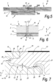
- Figure 5 is a top plan view of a floor covering 18 comprising a plurality of floor elements 1 coupled by means of the first coupling elements 11,12 along the longitudinal edges 10 and by means of the second coupling elements 16,17 along the transversal edges 15.
- Figure 6 on a larger scale shows a cross section along the line VI-VI of Figure 5 .
- the floor covering 18 comprises a grout 19 filling an intermediate distance I separating the decorative layers 2 of the floor elements 1.
- the intermediate distance I is twice the distance D1 between the upper edge of the support layer 3 and the edge of the decorative layer 3.
- Figure 6 further shows a section of the mechanical coupling between the firsts coupling elements 11,12 along a plane transversal to the longitudinal edges 10. Said mechanical coupling between the firsts coupling elements 11,12 is described in detail with the aid of Figure 7 .
- Figure 7 on a larger scale shows a view on the area F7 indicated on Figure 6 .
- the tongue 11 comprises a horizontal extending lip 20 and a downward projecting hump 21.
- the groove 12 has a horizontal recess 22, for receiving the lip 20 of the tongue 11, and an upward oriented hollow portion 23, for receiving the hump 21 of the tongue 11, so that tongue 11 can be fitted into the groove 12.
- Figure 7 also shows that in said coupled condition, the lip 20 is received by the recess 22.
- the upper surface of the lip 20 contacts un upper wall of the recess 22 thereby forming a first set of second locking surfaces 25 are formed limiting the mutual movement of said floor elements 1 in a substantially vertical direction Y.
- a horizontal inoperative space S1 between the tip of the lip 20 and the bottom of the recess 22 is established a horizontal inoperative space S1.
- a vertical inoperative space S2 between lower surface of the lip 20 and the recess 22 is established a vertical inoperative space S2.
- the downward projecting hump 21 of the tongue 11 is received by the hollow portion 23 of the groove 12.
- the lower surface of the downward projecting hump 21 contacts said hollow portion 23 so that a second set of second locking surfaces 25 is formed.
- the lower surface of the tongue 16 contacts the groove 12 exclusively in correspondence of the downward projecting hump 21.
- Figure 8 on a larger scale shows a cross section along the line VIII-VIII of Figure 5 .
- Figure 8 shows a section of the mechanical coupling between the second coupling elements 16,17 along a plane transversal to the transversal edges 15. Said mechanical coupling between the second coupling elements 16,17 is described in detail with the aid of figure 9 .
- the downward-directed lip and the upward-directed cavity form the first locking surface 24 for limiting mutual movement of the floor elements 1 in a horizontal direction Z perpendicular to the transversal edge 15.
- both the upper hook-shaped part 16 and the lower hook shaped part 17 comprise undercut portions 30 so that in the coupled condition the second locking surfaces 25 are formed to limit the mutual movement of the floor elements 1 in the vertical direction Y. More in particular, two sets of said second locking surfaces 25 are formed, for example on opposite sides of the male part and the female part.
- Figure 10 shows some steps of a method for manufacturing a floor element.
- the method comprises a first step S1 of providing the decorative layer 2.
- the decorative layer 2 is provided into a resin application station 40 wherein the uncured resin material R is provided, for example according to a pattern, onto a lower surface of the decorative layer 2.
- the uncured resin R preferably comprises a viscosity at 20°C less than 1000 mPas, preferably less 800 mPas, more preferably less 600 mPas, for example approximately 400 mPas. It is noted that in the resin application station 40 the decorative layer is placed with the upper surface, comprising the décor 6, facing down.
- a step S3 the semi-finished sandwich 42 is carried into a pressing station 43 wherein the layers 2,3 are pressed together for forming the floor element 1 such that the resin material permeates the pores of the ceramic material of the decorative layer 2 and forms the intermediate layer 13.
- the pressure is maintained for a pressing time of at least 1 second, preferably 30 seconds so that the uncured resin R can flow covering, at least 80 %, preferably 100% of the lower surface of the decorative layer 2.
- said pressing time is necessary to let the uncured resin R permeates the decorative layer 2.
- a pressure of at least 350 kg/sqm is exerted onto the layers.
Landscapes
- Engineering & Computer Science (AREA)
- Architecture (AREA)
- Ceramic Engineering (AREA)
- Civil Engineering (AREA)
- Structural Engineering (AREA)
- Chemical & Material Sciences (AREA)
- Physics & Mathematics (AREA)
- Fluid Mechanics (AREA)
- Floor Finish (AREA)
Claims (12)
- Élément de sol (1) destiné à former un revêtement de sol, dans lequel cet élément de sol (1) comprend une couche décorative (2) réalisée à partir d'une matière céramique et une couche de support (3) qui est disposée en dessous de cette couche décorative (2) ; dans lequel la couche de support (3) comprend des bords (10,15) qui sont munis d'éléments d'accouplement (11, 12, 16, 17) configurés pour mettre en œuvre un accouplement mécanique avec des éléments d'accouplement (11, 12, 16, 17) d'un élément de sol adjacent (1) ; et dans lequel l'élément de sol (1) comprend une couche intermédiaire (13) qui possède une matière à base de résine qui imprègne une surface inférieure de la couche décorative ; caractérisé en ce que la couche de support (3) comprend du PVC rigide ; et en ce que la couche de support (3) possède une élasticité en flexion entre 1,5 et 3,5 GPa.
- Élément de sol (1) selon la revendication (1), dans lequel la matière à base de résine comprend une résine époxy.
- Élément de sol (1) selon l'une quelconque des revendications précédentes, dans lequel la matière à base de résine possède une viscosité à 20 °C qui est inférieure à 1000 mPa.s
- Élément de sol (1) selon l'une quelconque des revendications précédentes, dans lequel la couche intermédiaire (13) recouvre 80 % ou plus de la surface inférieure de la couche décorative (2).
- Élément de sol (1) selon l'une quelconque des revendications précédentes, dans lequel la couche intermédiaire (13) possède une teneur en résine qui s'élève à au moins 150 g/m2.
- Élément de sol (1) selon l'une quelconque des revendications précédentes, dans lequel la couche intermédiaire (13) représente une couche adhésive qui lie l'une à l'autre par collage la couche décorative (2) et la couche de support (3).
- Élément de sol (1) selon l'une quelconque des revendications précédentes, dans lequel la couche décorative (2) possède une porosité apparente qui est comprise entre 0,1 % et 10 % telle qu'on la mesure en conformité avec la norme ASTM C373.
- Élément de sol (1) selon l'une quelconque des revendications précédentes, dans lequel la couche décorative (2) possède un volume de pores ouverts (14) qui est compris entre 0,01 cm3 et 1 cm3, tel qu'on le mesure en conformité avec la norme ASTM C373.
- Élément de sol (1) selon l'une quelconque des revendications précédentes, dans lequel la couche décorative (2) comprend un carreau en céramique à pâte rouge.
- Élément de sol (1) selon l'une quelconque des revendications précédentes, dans lequel la couche décorative (2) comprend une surface supérieure émaillée.
- Élément de sol (1) selon l'une quelconque des revendications précédentes, dans lequel couche de support (3) possède une épaisseur (T2) qui est inférieure 6 mm.
- Revêtement de sol (18) qui comprend un certain nombre d'éléments de sol (1) en conformité avec l'une quelconque des revendications précédentes.
Applications Claiming Priority (3)
| Application Number | Priority Date | Filing Date | Title |
|---|---|---|---|
| US16/028,745 US10563411B2 (en) | 2018-07-06 | 2018-07-06 | Floor element for forming a floor covering, a floor covering, and a method for manufacturing a floor element |
| PCT/US2019/040083 WO2020009973A1 (fr) | 2018-07-06 | 2019-07-01 | Élément de sol pour la formation d'un revêtement de sol, revêtement de sol, et procédé de fabrication d'un élément de sol |
| PCT/US2020/017696 WO2021002888A1 (fr) | 2018-07-06 | 2020-02-11 | Élément de plancher pour former un revêtement de plancher, revêtement de plancher et procédé de fabrication d'un élément de plancher |
Publications (3)
| Publication Number | Publication Date |
|---|---|
| EP3994319A1 EP3994319A1 (fr) | 2022-05-11 |
| EP3994319A4 EP3994319A4 (fr) | 2023-06-28 |
| EP3994319B1 true EP3994319B1 (fr) | 2025-04-09 |
Family
ID=69060563
Family Applications (3)
| Application Number | Title | Priority Date | Filing Date |
|---|---|---|---|
| EP19830455.2A Active EP3818124B1 (fr) | 2018-07-06 | 2019-07-01 | Élément de sol pour la formation d'un revêtement de sol, revêtement de sol, et procédé de fabrication d'un élément de sol |
| EP25163732.8A Pending EP4545288A3 (fr) | 2018-07-06 | 2019-07-01 | Élément de plancher pour former un revêtement de plancher, revêtement de plancher et procédé de fabrication d'un élément de plancher. |
| EP20835518.0A Active EP3994319B1 (fr) | 2018-07-06 | 2020-02-11 | Élément de plancher pour former un revêtement de plancher et revêtement de plancher |
Family Applications Before (2)
| Application Number | Title | Priority Date | Filing Date |
|---|---|---|---|
| EP19830455.2A Active EP3818124B1 (fr) | 2018-07-06 | 2019-07-01 | Élément de sol pour la formation d'un revêtement de sol, revêtement de sol, et procédé de fabrication d'un élément de sol |
| EP25163732.8A Pending EP4545288A3 (fr) | 2018-07-06 | 2019-07-01 | Élément de plancher pour former un revêtement de plancher, revêtement de plancher et procédé de fabrication d'un élément de plancher. |
Country Status (10)
| Country | Link |
|---|---|
| US (8) | US10563411B2 (fr) |
| EP (3) | EP3818124B1 (fr) |
| CN (3) | CN112534016B (fr) |
| AR (2) | AR116218A1 (fr) |
| CA (1) | CA3104184A1 (fr) |
| EA (1) | EA202190216A1 (fr) |
| ES (2) | ES3034788T3 (fr) |
| MX (2) | MX2021000175A (fr) |
| PL (2) | PL3818124T3 (fr) |
| WO (2) | WO2020009973A1 (fr) |
Families Citing this family (31)
| Publication number | Priority date | Publication date | Assignee | Title |
|---|---|---|---|---|
| US10563411B2 (en) * | 2018-07-06 | 2020-02-18 | Daltile Corporation | Floor element for forming a floor covering, a floor covering, and a method for manufacturing a floor element |
| ES2916708T3 (es) | 2019-01-23 | 2022-07-05 | Flooring Technologies Ltd | Procedimiento para la fabricación de un panel multicapa resistente a la abrasión y al agua |
| US10677275B1 (en) * | 2019-02-18 | 2020-06-09 | Daltile Corporation | Floor element for forming a floor covering, a floor covering and a method for manufacturing a floor element |
| ES2917414T3 (es) * | 2019-03-01 | 2022-07-08 | Flooring Technologies Ltd | Procedimiento para la fabricación de un panel multicapa con una estructura superficial con una estructura superficial y panel fabricado con este procedimiento |
| EP3706516B1 (fr) * | 2019-03-07 | 2024-11-20 | !OBAC Limited | Système de plancher dissipatif statique |
| IT201900015117A1 (it) * | 2019-08-29 | 2021-03-01 | Flooring Ind Ltd Sarl | Un elemento di copertura per pavimenti e una copertura per pavimenti |
| US11339576B2 (en) | 2019-09-17 | 2022-05-24 | Daltile Corporation | Floor element for forming a floor covering and a floor covering |
| US11559961B2 (en) | 2019-09-17 | 2023-01-24 | Daltile Corporation | Pressing equipment, a plant and a method for forming a floor element |
| CA3153635A1 (fr) * | 2019-09-25 | 2021-04-01 | Valinge Innovation Ab | Panneau dote d'un dispositif de verrouillage |
| US11927020B2 (en) | 2020-01-31 | 2024-03-12 | Champion Link International Corporation | Floor panel and method of manufacturing a floor panel |
| US11718565B2 (en) | 2020-01-31 | 2023-08-08 | Champion Link International Corporation | Panel for forming a floor covering and such floor covering |
| EP4103792A4 (fr) * | 2020-02-12 | 2024-02-28 | Dal-Tile, LLC | Tuile de toit et couverture de toit |
| CN111255191A (zh) * | 2020-03-16 | 2020-06-09 | 广州万构建筑工程设计有限公司 | 一种半预贴式瓷砖及其铺贴方法 |
| DK4121616T3 (da) * | 2020-03-19 | 2025-12-15 | I4F Licensing Nv | Flisepanel og en overfladebelægning konstrueret af en flerhed af tilstødende flisepaneler |
| RU200270U1 (ru) * | 2020-04-20 | 2020-10-15 | Владимир Григорьевич Антоненков | Тактильная плитка |
| US11359386B2 (en) | 2020-05-07 | 2022-06-14 | Dal-Tile Corporation | Floor element for forming a floor covering, a floor covering, and a method for manufacturing a floor element |
| US11840846B2 (en) | 2020-05-12 | 2023-12-12 | Valinge Innovation Ab | Mineral-based panel |
| US11530536B2 (en) | 2020-07-15 | 2022-12-20 | Champion Link International Corporation | Panel |
| NL2026068B1 (en) * | 2020-07-15 | 2022-03-21 | Champion Link Int Corp | Panel |
| US11326356B2 (en) * | 2020-07-15 | 2022-05-10 | Champion Link International Corporation | Floor or wall panel |
| NL2026069B1 (en) * | 2020-07-15 | 2022-03-21 | Champion Link Int Corp | Panel |
| NL2028108B1 (en) * | 2021-04-30 | 2022-11-09 | Champion Link Int Corp | Flooring panel |
| US12545013B2 (en) | 2021-04-30 | 2026-02-10 | Champion Link International Corporation | Flooring panel |
| NL2029278B1 (en) | 2021-09-29 | 2023-04-06 | Champion Link Int Corp | Decorative panel and method for producing decorative panel |
| NL2029282B1 (en) | 2021-09-30 | 2023-04-06 | I4F Licensing Nv | Decorative panel, in particular a wall, floor or ceiling panel, a surface covering constructed by a multitude of such panels, method of producing such a panel, and a surface covering which is constructed by a multitude of such panels |
| NL2029346B1 (en) | 2021-10-07 | 2023-04-20 | Champion Link Int Corp | Decorative panel and method for producing a panel |
| NL2029345B1 (en) | 2021-10-07 | 2023-04-20 | Champion Link Int Corp | Decorative panel |
| BE1030080B1 (nl) * | 2021-12-23 | 2023-07-24 | Flooring Ind Ltd Sarl | Paneel |
| NL2030461B1 (en) | 2022-01-07 | 2023-07-12 | Champion Link Int Corp | Decorative panel and method for producing a panel |
| EP4496861A4 (fr) * | 2022-03-21 | 2026-04-01 | Brady Worldwide Inc | Bande de marquage au sol |
| WO2025104663A1 (fr) * | 2023-11-17 | 2025-05-22 | Dal-Tile, Llc | Système et procédé pour dalles décoratives légères |
Family Cites Families (52)
| Publication number | Priority date | Publication date | Assignee | Title |
|---|---|---|---|---|
| NL127873C (fr) | 1959-07-28 | 1900-01-01 | ||
| US3239981A (en) | 1961-12-12 | 1966-03-15 | Tile Council Of America | Ceramic products |
| NL7404079A (nl) * | 1974-03-26 | 1975-09-30 | Lucas Gijsbert Van Der Linden | Decoratieve bouw- en/of bestratingstegel. |
| US4993208A (en) * | 1987-09-29 | 1991-02-19 | Buchtal Gesellschaft Mit Beschrankter Haftung | Mold for producing tile-shaped floor elements for forming a double floor construction and a corresponding tile-shaped floor element |
| BE1010487A6 (nl) | 1996-06-11 | 1998-10-06 | Unilin Beheer Bv | Vloerbekleding bestaande uit harde vloerpanelen en werkwijze voor het vervaardigen van dergelijke vloerpanelen. |
| US6344268B1 (en) * | 1998-04-03 | 2002-02-05 | Certainteed Corporation | Foamed polymer-fiber composite |
| US20060065993A1 (en) * | 1998-04-03 | 2006-03-30 | Certainteed Corporation | Foamed polymer-fiber composite |
| SE512290C2 (sv) | 1998-06-03 | 2000-02-28 | Valinge Aluminium Ab | Låssystem för mekanisk hopfogning av golvskivor samt golvskiva försedd med låssystemet |
| SE517183C2 (sv) | 2000-01-24 | 2002-04-23 | Valinge Aluminium Ab | Låssystem för mekanisk hopfogning av golvskivor, golvskiva försedd med låssystemet och metod för framställning av sådana golvskivor |
| BE1013569A3 (nl) | 2000-06-20 | 2002-04-02 | Unilin Beheer Bv | Vloerbekleding. |
| SE525657C2 (sv) | 2002-04-08 | 2005-03-29 | Vaelinge Innovation Ab | Golvskivor för flytande golv framställda av åtminstone två olika materialskikt samt halvfabrikat för tillverkning av golvskivor |
| US7677001B2 (en) | 2003-03-06 | 2010-03-16 | Valinge Innovation Ab | Flooring systems and methods for installation |
| US7845140B2 (en) | 2003-03-06 | 2010-12-07 | Valinge Innovation Ab | Flooring and method for installation and manufacturing thereof |
| US7442423B2 (en) | 2003-04-28 | 2008-10-28 | Shaw Industries Group | Hard surface-veneer engineered surfacing tiles |
| AU2006249208B2 (en) * | 2004-05-26 | 2010-01-21 | Studioart Srl | Covering Element, Method and Machine to Produce Said Covering Element |
| US7446138B2 (en) * | 2005-04-29 | 2008-11-04 | Board Of Trustees Of Michigan State University | Wood particle filled polyvinyl chloride composites and their foams |
| BE1017049A6 (nl) * | 2006-04-06 | 2007-12-04 | Flooring Ind Ltd | Werkwijze voor het vervaardigen van vloerpanelen en vloerpaneel. |
| US7984600B2 (en) | 2007-02-02 | 2011-07-26 | Mohawk Carpet Corporation | Groutless tile system and method for making the same |
| WO2009061279A1 (fr) | 2007-11-07 | 2009-05-14 | Välinge Innovation AB | Blocage mécanique de panneaux de sol avec encliquetage sur pliure verticale et procédé d'installation pour relier ces panneaux |
| US8353140B2 (en) | 2007-11-07 | 2013-01-15 | Valinge Innovation Ab | Mechanical locking of floor panels with vertical snap folding |
| US20090223162A1 (en) | 2008-03-05 | 2009-09-10 | Mannington Mills, Inc. | Connecting System For Surface Coverings |
| KR101050399B1 (ko) | 2008-05-20 | 2011-07-19 | 현대산업개발 주식회사 | 복수의 방수시트를 이용한 방수공법 |
| ITMO20080330A1 (it) | 2008-12-24 | 2010-06-25 | Mariano Paganelli | Procedimento per realizzare piastrelle ad alta resistenza destinate al rivestimento di pavimentazioni e di pareti interne o esterne. |
| BE1018728A3 (nl) * | 2009-04-22 | 2011-07-05 | Flooring Ind Ltd Sarl | Vloerpaneel. |
| US8266849B2 (en) | 2009-05-27 | 2012-09-18 | Mcfarland Cascade Holdings, Inc. | Interlocking platform panels and modules |
| US8925275B2 (en) | 2010-05-10 | 2015-01-06 | Flooring Industries Limited, Sarl | Floor panel |
| CN101845880B (zh) * | 2010-06-07 | 2011-10-05 | 浙江嘉业地板有限公司 | 防翘专家地板及其生产方法 |
| CN102504736A (zh) * | 2011-11-07 | 2012-06-20 | 北华大学 | 实木复合地板用酚醛树脂复合填充剂及其酚醛树脂胶黏剂 |
| KR102069909B1 (ko) * | 2012-02-07 | 2020-01-23 | 플로어링 인더스트리즈 리미티드 에스에이알엘 | 플로어 커버링을 형성하기 위한 플로어 패널, 그러한 플로어 패널들로부터 형성된 플로어 커버링 및 그러한 플로어 패널들의 제작 방법 |
| US9140010B2 (en) | 2012-07-02 | 2015-09-22 | Valinge Flooring Technology Ab | Panel forming |
| US20140349084A1 (en) | 2013-05-24 | 2014-11-27 | Mohawk Carpet Corporation | Composite tile systems and methods |
| WO2015060778A1 (fr) | 2013-10-23 | 2015-04-30 | Floor Iptech Ab | Procédé de formation d'une couche décorative résistante à l'usure |
| DE102013113130B4 (de) | 2013-11-27 | 2022-01-27 | Välinge Innovation AB | Verfahren zur Herstellung einer Fußbodendiele |
| DE102013113109A1 (de) | 2013-11-27 | 2015-06-11 | Guido Schulte | Fußbodendiele |
| EP3808921B1 (fr) | 2013-12-20 | 2025-09-10 | Unilin, BV | Carreau céramique et procédé de fabrication de carreaux céramiques |
| UA117159C2 (uk) | 2014-01-14 | 2018-06-25 | Кроноплюс Текнікал Аг | Багатошарова будівельна плита для внутрішнього та зовнішнього застосування |
| EP2905145B1 (fr) | 2014-02-06 | 2019-10-23 | Unilin, BVBA | Procédé de fabrication des panneaux de plancher ayant une surface décorative |
| US10876301B2 (en) | 2014-09-30 | 2020-12-29 | Akzenta Paneele + Profile Gmbh | Panel with complimentary locking elements |
| DE202014010455U1 (de) | 2014-09-30 | 2015-08-03 | Akzenta Paneele + Profile Gmbh | Paneel |
| KR102469131B1 (ko) * | 2015-01-14 | 2022-11-18 | 뵈린게 이노베이션 에이비이 | 상이한 광택 레벨들을 갖는 내마모성 층을 제조하는 방법 |
| US9896851B1 (en) * | 2015-04-14 | 2018-02-20 | The Matworks Copmany LLC | Hard surface veneer and wood polymer composite flooring tile |
| CN205000580U (zh) * | 2015-06-05 | 2016-01-27 | 欧元贸易地板公司 | 用于水平表面和垂直表面的装饰性多层覆盖物 |
| BE1023542B1 (nl) | 2015-10-27 | 2017-04-28 | Unilin Bvba | Vloerpaneel en werkwijze voor het vervaardigen van vloerpanelen |
| ES2927610T3 (es) * | 2016-03-23 | 2022-11-08 | Li & Co AG | Elemento de revestimiento de pared o suelo |
| US20190202178A1 (en) | 2016-08-18 | 2019-07-04 | Välinge Innovation AB | A method to coat a building panel and such a coated building panel |
| TW201842264A (zh) | 2017-04-18 | 2018-12-01 | 英商英威達紡織(英國)有限公司 | 易安裝的陶瓷或石磚產品 |
| ES2902394T3 (es) | 2017-05-15 | 2022-03-28 | Flooring Ind Ltd Sarl | Un elemento de suelo para formar un revestimiento de suelo y un revestimiento de suelo |
| NL2018970B1 (en) | 2017-05-23 | 2018-12-04 | Innovations 4 Flooring Holding Nv | Multi-purpose tile system |
| US10563411B2 (en) * | 2018-07-06 | 2020-02-18 | Daltile Corporation | Floor element for forming a floor covering, a floor covering, and a method for manufacturing a floor element |
| US10677275B1 (en) * | 2019-02-18 | 2020-06-09 | Daltile Corporation | Floor element for forming a floor covering, a floor covering and a method for manufacturing a floor element |
| US11339576B2 (en) * | 2019-09-17 | 2022-05-24 | Daltile Corporation | Floor element for forming a floor covering and a floor covering |
| US11359386B2 (en) * | 2020-05-07 | 2022-06-14 | Dal-Tile Corporation | Floor element for forming a floor covering, a floor covering, and a method for manufacturing a floor element |
-
2018
- 2018-07-06 US US16/028,745 patent/US10563411B2/en active Active
-
2019
- 2019-07-01 US US17/258,207 patent/US12110694B2/en active Active
- 2019-07-01 PL PL19830455.2T patent/PL3818124T3/pl unknown
- 2019-07-01 CA CA3104184A patent/CA3104184A1/fr active Pending
- 2019-07-01 CN CN201980044874.8A patent/CN112534016B/zh active Active
- 2019-07-01 ES ES19830455T patent/ES3034788T3/es active Active
- 2019-07-01 WO PCT/US2019/040083 patent/WO2020009973A1/fr not_active Ceased
- 2019-07-01 EP EP19830455.2A patent/EP3818124B1/fr active Active
- 2019-07-01 MX MX2021000175A patent/MX2021000175A/es unknown
- 2019-07-01 EP EP25163732.8A patent/EP4545288A3/fr active Pending
- 2019-07-01 EA EA202190216A patent/EA202190216A1/ru unknown
- 2019-07-05 AR ARP190101917A patent/AR116218A1/es unknown
-
2020
- 2020-01-02 US US16/732,421 patent/US10760285B2/en active Active
- 2020-01-02 US US16/732,399 patent/US10822810B2/en active Active
- 2020-02-11 WO PCT/US2020/017696 patent/WO2021002888A1/fr not_active Ceased
- 2020-02-11 CN CN202311386939.1A patent/CN117418662A/zh active Pending
- 2020-02-11 US US17/624,279 patent/US12366073B2/en active Active
- 2020-02-11 EP EP20835518.0A patent/EP3994319B1/fr active Active
- 2020-02-11 CN CN202080059512.9A patent/CN114341447B/zh active Active
- 2020-02-11 PL PL20835518.0T patent/PL3994319T3/pl unknown
- 2020-02-11 ES ES20835518T patent/ES3034204T3/es active Active
- 2020-02-14 AR ARP200100407A patent/AR118092A1/es unknown
- 2020-07-24 US US16/937,754 patent/US11326357B2/en active Active
-
2021
- 2021-01-06 MX MX2025015476A patent/MX2025015476A/es unknown
-
2024
- 2024-05-02 US US18/653,083 patent/US12460425B2/en active Active
-
2025
- 2025-10-13 US US19/356,369 patent/US20260035934A1/en active Pending
Also Published As
Similar Documents
| Publication | Publication Date | Title |
|---|---|---|
| EP3994319B1 (fr) | Élément de plancher pour former un revêtement de plancher et revêtement de plancher | |
| US12152626B2 (en) | Floor element for forming a floor covering, a floor covering, and a method for manufacturing a floor element | |
| US12366074B2 (en) | Floor element for forming a floor covering, a floor covering, and a method for manufacturing a floor element | |
| EP3404165B1 (fr) | Élément de plancher pour former un revêtement de plancher et revêtement de plancher | |
| EA040976B1 (ru) | Напольный элемент для формирования напольного покрытия, напольное покрытие и способ изготовления напольного элемента |
Legal Events
| Date | Code | Title | Description |
|---|---|---|---|
| STAA | Information on the status of an ep patent application or granted ep patent |
Free format text: STATUS: THE INTERNATIONAL PUBLICATION HAS BEEN MADE |
|
| PUAI | Public reference made under article 153(3) epc to a published international application that has entered the european phase |
Free format text: ORIGINAL CODE: 0009012 |
|
| STAA | Information on the status of an ep patent application or granted ep patent |
Free format text: STATUS: REQUEST FOR EXAMINATION WAS MADE |
|
| 17P | Request for examination filed |
Effective date: 20220111 |
|
| AK | Designated contracting states |
Kind code of ref document: A1 Designated state(s): AL AT BE BG CH CY CZ DE DK EE ES FI FR GB GR HR HU IE IS IT LI LT LU LV MC MK MT NL NO PL PT RO RS SE SI SK SM TR |
|
| DAV | Request for validation of the european patent (deleted) | ||
| DAX | Request for extension of the european patent (deleted) | ||
| A4 | Supplementary search report drawn up and despatched |
Effective date: 20230530 |
|
| RIC1 | Information provided on ipc code assigned before grant |
Ipc: E04F 15/08 20060101ALI20230523BHEP Ipc: E04F 15/04 20060101ALI20230523BHEP Ipc: E04F 15/02 20060101AFI20230523BHEP |
|
| RAP3 | Party data changed (applicant data changed or rights of an application transferred) |
Owner name: DAL-TILE, LLC |
|
| GRAP | Despatch of communication of intention to grant a patent |
Free format text: ORIGINAL CODE: EPIDOSNIGR1 |
|
| STAA | Information on the status of an ep patent application or granted ep patent |
Free format text: STATUS: GRANT OF PATENT IS INTENDED |
|
| INTG | Intention to grant announced |
Effective date: 20241004 |
|
| GRAS | Grant fee paid |
Free format text: ORIGINAL CODE: EPIDOSNIGR3 |
|
| P01 | Opt-out of the competence of the unified patent court (upc) registered |
Free format text: CASE NUMBER: APP_2628/2025 Effective date: 20250116 |
|
| GRAA | (expected) grant |
Free format text: ORIGINAL CODE: 0009210 |
|
| STAA | Information on the status of an ep patent application or granted ep patent |
Free format text: STATUS: THE PATENT HAS BEEN GRANTED |
|
| AK | Designated contracting states |
Kind code of ref document: B1 Designated state(s): AL AT BE BG CH CY CZ DE DK EE ES FI FR GB GR HR HU IE IS IT LI LT LU LV MC MK MT NL NO PL PT RO RS SE SI SK SM TR |
|
| REG | Reference to a national code |
Ref country code: GB Ref legal event code: FG4D |
|
| REG | Reference to a national code |
Ref country code: CH Ref legal event code: EP |
|
| REG | Reference to a national code |
Ref country code: DE Ref legal event code: R096 Ref document number: 602020049240 Country of ref document: DE |
|
| REG | Reference to a national code |
Ref country code: IE Ref legal event code: FG4D |
|
| REG | Reference to a national code |
Ref country code: NL Ref legal event code: FP |
|
| REG | Reference to a national code |
Ref country code: ES Ref legal event code: FG2A Ref document number: 3034204 Country of ref document: ES Kind code of ref document: T3 Effective date: 20250813 |
|
| REG | Reference to a national code |
Ref country code: AT Ref legal event code: MK05 Ref document number: 1783636 Country of ref document: AT Kind code of ref document: T Effective date: 20250409 |
|
| PG25 | Lapsed in a contracting state [announced via postgrant information from national office to epo] |
Ref country code: FI Free format text: LAPSE BECAUSE OF FAILURE TO SUBMIT A TRANSLATION OF THE DESCRIPTION OR TO PAY THE FEE WITHIN THE PRESCRIBED TIME-LIMIT Effective date: 20250409 Ref country code: PT Free format text: LAPSE BECAUSE OF FAILURE TO SUBMIT A TRANSLATION OF THE DESCRIPTION OR TO PAY THE FEE WITHIN THE PRESCRIBED TIME-LIMIT Effective date: 20250811 |
|
| REG | Reference to a national code |
Ref country code: LT Ref legal event code: MG9D |
|
| PG25 | Lapsed in a contracting state [announced via postgrant information from national office to epo] |
Ref country code: GR Free format text: LAPSE BECAUSE OF FAILURE TO SUBMIT A TRANSLATION OF THE DESCRIPTION OR TO PAY THE FEE WITHIN THE PRESCRIBED TIME-LIMIT Effective date: 20250710 Ref country code: NO Free format text: LAPSE BECAUSE OF FAILURE TO SUBMIT A TRANSLATION OF THE DESCRIPTION OR TO PAY THE FEE WITHIN THE PRESCRIBED TIME-LIMIT Effective date: 20250709 |
|
| PG25 | Lapsed in a contracting state [announced via postgrant information from national office to epo] |
Ref country code: BG Free format text: LAPSE BECAUSE OF FAILURE TO SUBMIT A TRANSLATION OF THE DESCRIPTION OR TO PAY THE FEE WITHIN THE PRESCRIBED TIME-LIMIT Effective date: 20250409 |
|
| PG25 | Lapsed in a contracting state [announced via postgrant information from national office to epo] |
Ref country code: HR Free format text: LAPSE BECAUSE OF FAILURE TO SUBMIT A TRANSLATION OF THE DESCRIPTION OR TO PAY THE FEE WITHIN THE PRESCRIBED TIME-LIMIT Effective date: 20250409 |
|
| PG25 | Lapsed in a contracting state [announced via postgrant information from national office to epo] |
Ref country code: AT Free format text: LAPSE BECAUSE OF FAILURE TO SUBMIT A TRANSLATION OF THE DESCRIPTION OR TO PAY THE FEE WITHIN THE PRESCRIBED TIME-LIMIT Effective date: 20250409 |
|
| PG25 | Lapsed in a contracting state [announced via postgrant information from national office to epo] |
Ref country code: RS Free format text: LAPSE BECAUSE OF FAILURE TO SUBMIT A TRANSLATION OF THE DESCRIPTION OR TO PAY THE FEE WITHIN THE PRESCRIBED TIME-LIMIT Effective date: 20250709 |
|
| PG25 | Lapsed in a contracting state [announced via postgrant information from national office to epo] |
Ref country code: IS Free format text: LAPSE BECAUSE OF FAILURE TO SUBMIT A TRANSLATION OF THE DESCRIPTION OR TO PAY THE FEE WITHIN THE PRESCRIBED TIME-LIMIT Effective date: 20250809 |
|
| PG25 | Lapsed in a contracting state [announced via postgrant information from national office to epo] |
Ref country code: LV Free format text: LAPSE BECAUSE OF FAILURE TO SUBMIT A TRANSLATION OF THE DESCRIPTION OR TO PAY THE FEE WITHIN THE PRESCRIBED TIME-LIMIT Effective date: 20250409 |
|
| REG | Reference to a national code |
Ref country code: DE Ref legal event code: R097 Ref document number: 602020049240 Country of ref document: DE |
|
| PG25 | Lapsed in a contracting state [announced via postgrant information from national office to epo] |
Ref country code: DK Free format text: LAPSE BECAUSE OF FAILURE TO SUBMIT A TRANSLATION OF THE DESCRIPTION OR TO PAY THE FEE WITHIN THE PRESCRIBED TIME-LIMIT Effective date: 20250409 Ref country code: SM Free format text: LAPSE BECAUSE OF FAILURE TO SUBMIT A TRANSLATION OF THE DESCRIPTION OR TO PAY THE FEE WITHIN THE PRESCRIBED TIME-LIMIT Effective date: 20250409 |
|
| PG25 | Lapsed in a contracting state [announced via postgrant information from national office to epo] |
Ref country code: CZ Free format text: LAPSE BECAUSE OF FAILURE TO SUBMIT A TRANSLATION OF THE DESCRIPTION OR TO PAY THE FEE WITHIN THE PRESCRIBED TIME-LIMIT Effective date: 20250409 |
|
| PG25 | Lapsed in a contracting state [announced via postgrant information from national office to epo] |
Ref country code: EE Free format text: LAPSE BECAUSE OF FAILURE TO SUBMIT A TRANSLATION OF THE DESCRIPTION OR TO PAY THE FEE WITHIN THE PRESCRIBED TIME-LIMIT Effective date: 20250409 |
|
| PG25 | Lapsed in a contracting state [announced via postgrant information from national office to epo] |
Ref country code: SK Free format text: LAPSE BECAUSE OF FAILURE TO SUBMIT A TRANSLATION OF THE DESCRIPTION OR TO PAY THE FEE WITHIN THE PRESCRIBED TIME-LIMIT Effective date: 20250409 Ref country code: RO Free format text: LAPSE BECAUSE OF FAILURE TO SUBMIT A TRANSLATION OF THE DESCRIPTION OR TO PAY THE FEE WITHIN THE PRESCRIBED TIME-LIMIT Effective date: 20250409 |
|
| PLBE | No opposition filed within time limit |
Free format text: ORIGINAL CODE: 0009261 |
|
| STAA | Information on the status of an ep patent application or granted ep patent |
Free format text: STATUS: NO OPPOSITION FILED WITHIN TIME LIMIT |
|
| REG | Reference to a national code |
Ref country code: CH Ref legal event code: L10 Free format text: ST27 STATUS EVENT CODE: U-0-0-L10-L00 (AS PROVIDED BY THE NATIONAL OFFICE) Effective date: 20260218 |
|
| PGFP | Annual fee paid to national office [announced via postgrant information from national office to epo] |
Ref country code: NL Payment date: 20260226 Year of fee payment: 7 |
|
| 26N | No opposition filed |
Effective date: 20260112 |
|
| PGFP | Annual fee paid to national office [announced via postgrant information from national office to epo] |
Ref country code: ES Payment date: 20260302 Year of fee payment: 7 |
|
| PGFP | Annual fee paid to national office [announced via postgrant information from national office to epo] |
Ref country code: DE Payment date: 20260227 Year of fee payment: 7 |
|
| PGFP | Annual fee paid to national office [announced via postgrant information from national office to epo] |
Ref country code: BE Payment date: 20260227 Year of fee payment: 7 Ref country code: IT Payment date: 20260219 Year of fee payment: 7 |
|
| PGFP | Annual fee paid to national office [announced via postgrant information from national office to epo] |
Ref country code: FR Payment date: 20260225 Year of fee payment: 7 |
|
| PGFP | Annual fee paid to national office [announced via postgrant information from national office to epo] |
Ref country code: TR Payment date: 20260127 Year of fee payment: 7 |