EP3994351B1 - Pale de rotor pour une éolienne, segment de pale de rotor, éolienne et procédé pour la fabrication d'une pale de rotor - Google Patents
Pale de rotor pour une éolienne, segment de pale de rotor, éolienne et procédé pour la fabrication d'une pale de rotor Download PDFInfo
- Publication number
- EP3994351B1 EP3994351B1 EP20732871.7A EP20732871A EP3994351B1 EP 3994351 B1 EP3994351 B1 EP 3994351B1 EP 20732871 A EP20732871 A EP 20732871A EP 3994351 B1 EP3994351 B1 EP 3994351B1
- Authority
- EP
- European Patent Office
- Prior art keywords
- rotor blade
- mounting elements
- laminate
- blade segment
- longitudinal direction
- Prior art date
- Legal status (The legal status is an assumption and is not a legal conclusion. Google has not performed a legal analysis and makes no representation as to the accuracy of the status listed.)
- Active
Links
Images





Classifications
-
- F—MECHANICAL ENGINEERING; LIGHTING; HEATING; WEAPONS; BLASTING
- F03—MACHINES OR ENGINES FOR LIQUIDS; WIND, SPRING, OR WEIGHT MOTORS; PRODUCING MECHANICAL POWER OR A REACTIVE PROPULSIVE THRUST, NOT OTHERWISE PROVIDED FOR
- F03D—WIND MOTORS
- F03D1/00—Wind motors with rotation axis substantially parallel to the air flow entering the rotor
- F03D1/06—Rotors
- F03D1/065—Rotors characterised by their construction elements
- F03D1/0675—Rotors characterised by their construction elements of the blades
-
- F—MECHANICAL ENGINEERING; LIGHTING; HEATING; WEAPONS; BLASTING
- F03—MACHINES OR ENGINES FOR LIQUIDS; WIND, SPRING, OR WEIGHT MOTORS; PRODUCING MECHANICAL POWER OR A REACTIVE PROPULSIVE THRUST, NOT OTHERWISE PROVIDED FOR
- F03D—WIND MOTORS
- F03D13/00—Assembly, mounting or commissioning of wind motors; Arrangements specially adapted for transporting wind motor components
- F03D13/10—Assembly of wind motors; Arrangements for erecting wind motors
-
- F—MECHANICAL ENGINEERING; LIGHTING; HEATING; WEAPONS; BLASTING
- F05—INDEXING SCHEMES RELATING TO ENGINES OR PUMPS IN VARIOUS SUBCLASSES OF CLASSES F01-F04
- F05B—INDEXING SCHEME RELATING TO WIND, SPRING, WEIGHT, INERTIA OR LIKE MOTORS, TO MACHINES OR ENGINES FOR LIQUIDS COVERED BY SUBCLASSES F03B, F03D AND F03G
- F05B2230/00—Manufacture
- F05B2230/60—Assembly methods
- F05B2230/61—Assembly methods using auxiliary equipment for lifting or holding
-
- F—MECHANICAL ENGINEERING; LIGHTING; HEATING; WEAPONS; BLASTING
- F05—INDEXING SCHEMES RELATING TO ENGINES OR PUMPS IN VARIOUS SUBCLASSES OF CLASSES F01-F04
- F05B—INDEXING SCHEME RELATING TO WIND, SPRING, WEIGHT, INERTIA OR LIKE MOTORS, TO MACHINES OR ENGINES FOR LIQUIDS COVERED BY SUBCLASSES F03B, F03D AND F03G
- F05B2240/00—Components
- F05B2240/20—Rotors
- F05B2240/30—Characteristics of rotor blades, i.e. of any element transforming dynamic fluid energy to or from rotational energy and being attached to a rotor
- F05B2240/302—Segmented or sectional blades
-
- F—MECHANICAL ENGINEERING; LIGHTING; HEATING; WEAPONS; BLASTING
- F05—INDEXING SCHEMES RELATING TO ENGINES OR PUMPS IN VARIOUS SUBCLASSES OF CLASSES F01-F04
- F05B—INDEXING SCHEME RELATING TO WIND, SPRING, WEIGHT, INERTIA OR LIKE MOTORS, TO MACHINES OR ENGINES FOR LIQUIDS COVERED BY SUBCLASSES F03B, F03D AND F03G
- F05B2280/00—Materials; Properties thereof
- F05B2280/60—Properties or characteristics given to material by treatment or manufacturing
- F05B2280/6003—Composites; e.g. fibre-reinforced
-
- Y—GENERAL TAGGING OF NEW TECHNOLOGICAL DEVELOPMENTS; GENERAL TAGGING OF CROSS-SECTIONAL TECHNOLOGIES SPANNING OVER SEVERAL SECTIONS OF THE IPC; TECHNICAL SUBJECTS COVERED BY FORMER USPC CROSS-REFERENCE ART COLLECTIONS [XRACs] AND DIGESTS
- Y02—TECHNOLOGIES OR APPLICATIONS FOR MITIGATION OR ADAPTATION AGAINST CLIMATE CHANGE
- Y02E—REDUCTION OF GREENHOUSE GAS [GHG] EMISSIONS, RELATED TO ENERGY GENERATION, TRANSMISSION OR DISTRIBUTION
- Y02E10/00—Energy generation through renewable energy sources
- Y02E10/70—Wind energy
- Y02E10/72—Wind turbines with rotation axis in wind direction
Definitions
- the invention relates to a rotor blade for a wind turbine, a wind turbine and a method for producing a rotor blade.
- Wind turbines of the type mentioned above are well known.
- the most common type of wind turbine currently is the so-called horizontal axis wind turbine, which is usually equipped with three rotor blades, although wind turbines with one, two, four or more rotor blades are also possible.
- wind turbines usually comprise a tower on which the nacelle with the rotor is arranged so that it can rotate around a substantially vertical axis.
- the rotor comprises a hub on which at least one rotor blade is arranged. The rotor blades are subject to both a static load due to the weight of the rotor blades and centrifugal forces that arise during rotation.
- Wind turbines are becoming increasingly larger in order to achieve a higher nominal output and to make better use of the wind.
- the rotor blades of wind turbines are usually manufactured in segments, with several rotor segments connected to one another. Such segmentation is essential, not least for transport reasons.
- connection points Due to the segmentation of the rotor blades, high static and dynamic forces act particularly on the connection points. Due to the increasingly larger designs, The static and dynamic forces are increased compared to smaller systems. As the size of the rotor blades increases, the demands on the connection points also increase.
- Assembly elements are usually used in such connection points. These assembly elements can be provided as additional elements in the form of bolts, which are screwed or laminated into the rotor blade segment and can be brought into engagement with corresponding receptacles on an adjacent rotor blade segment. In order to be able to absorb the loads that occur, such assembly elements must be dimensioned accordingly and thus lead to a considerable additional weight of the rotor blade.
- German Patent and Trademark Office has searched the following prior art in the priority application for the present application: US 8 348 622 B2 , US 2008/0 069 699 A1 , US 2016/0 341 177 A1 , US 2017/0 089 324 A1 , US 2018/0 298 879 A1 , WO 2003/0 78 833 A1 .
- Another example is from EP 3 144 526 A1 known.
- a rotor blade for a wind turbine having a longitudinal direction (L) in which the rotor blade extends, at least one first rotor blade segment with a first end face, and at least one second rotor blade segment with a second end face, wherein the first rotor blade segment is connected in the longitudinal direction, at the end face, to the second Rotor blade segment is coupled, wherein the first and the second rotor blade segment each comprise: a blade laminate with a plurality of laminate layers which are arranged stacked in a profile thickness direction (D), and a plurality of mounting elements arranged at the end for coupling the first rotor blade segment to the second rotor blade segment, wherein each of the mounting elements extends in the longitudinal direction, has two contact surfaces which are arranged transversely, in particular orthogonally, to the longitudinal direction (L) at a distance from one another which decreases non-linearly at the end.
- L longitudinal direction
- D profile thickness direction
- Such a non-linear reduction in the distance between the contact surfaces can reduce stress increases at the tip of the mounting element.
- the stresses in the loaded area at the tip can thus be reduced by a comparatively small, particularly gentle reduction in the distance between the contact surfaces.
- the reduction in the distance can, for example, increase more steeply, since the loads on the connection are comparatively low in this area.
- the mounting elements thus provide an easy and secure connection between adjacent rotor blade segments.
- the invention is based, among other things, on the finding that the design described here can overcome disadvantages of finger-joint joints that are known from distant technical fields, such as timber construction, and that would otherwise prevent them from being used for rotor blades of large wind turbines.
- the invention is based, among other things, on the finding that existing finger-jointed joints intended for use in rotor blades, such as US 8 348 622 B2 and US2016341177 A1 , in particular stress increases at the tip of each finger joint are disadvantageous, which are concentrated at this point due to a jump in stiffness. These stress increases lead to a massive load on the connection and in particular on the bonding point and increase the adhesive stresses and lead to a notch effect in the adjacent area of the sheet laminate. These stress increases at the tip of the finger joint can lead to the adhesive coming off and, as a result, to the connection failing.
- the present invention reduces these disadvantages.
- the non-linear reduction in the distance between the contact surfaces of the respective mounting element means in particular that the mounting element tapers in the longitudinal direction, starting from the sheet laminate.
- the taper of the mounting element is non-linear.
- Such a rotor blade preferably has a root region and a blade tip, the rotor blade extending in the longitudinal direction (L) between the root region and the blade tip. Furthermore, such a rotor blade preferably has a leading edge that runs essentially in the longitudinal direction and a trailing edge that is spaced apart in a profile depth direction (Q) of the rotor blade and runs in the longitudinal direction.
- the profile thickness direction (D) is not understood to be a global direction of the rotor blade, but rather locally in the region of one mounting element or several adjacent mounting elements, preferably the normal of the plane that is formed by the laminate layers. For example, in the case of a cylindrical rotor blade segment, the profile thickness direction (D) thus corresponds to one radial of the rotor blade segment.
- the plurality of mounting elements are arranged adjacent to one another in a plane (E) orthogonal to the longitudinal direction (L), and a free space is formed between each two adjacent mounting elements, in which a corresponding mounting element is accommodated such that the contact surfaces of the accommodated mounting element are in contact with one of the contact surfaces of the two adjacent mounting elements.
- the plurality of mounting elements can transmit forces between the rotor blade segments, in particular over a large area. It is in the spirit of the invention that the mounting elements are arranged adjacent to one another at a distance from one another in the profile depth direction (Q), and that the mounting elements are arranged adjacent to one another at a distance from one another in the profile thickness direction (D).
- the plane (E) is defined here by the profile depth direction (Q) and the profile thickness direction (D), whereby the longitudinal direction (L) is the surface normal of the plane (E).
- the contact surfaces of the received mounting element are each connected to one of the contact surfaces of the two adjacent mounting elements bonded together, in particular by means of an adhesive which is applied to the contact surfaces of the two adjacent assembly elements and/or the contact surfaces of the received assembly element.
- a bonded connection using the contact surfaces provides a flat and therefore material-appropriate or fiber composite-appropriate joint. Joining using an adhesive is particularly advantageous because production-related and material-related shape and position deviations can be compensated for.
- the first and the second rotor blade segment each comprise: at least one reinforcement structure for absorbing longitudinal forces, which extends along the rotor blade segment in the longitudinal direction (L), wherein the mounting elements are each arranged on the front side in the region of the respective reinforcement structure, and couple the reinforcement structure of the first rotor blade segment to the reinforcement structure of the second rotor blade segment.
- Such reinforcement structures generally absorb a large part of the forces acting in the longitudinal direction.
- the reinforcement structure further preferably has at least one laminate layer, preferably a plurality of laminate layers, made of a unidirectional fabric, each of which is oriented in the longitudinal direction (L), and wherein the majority of the mounting elements are integrally formed on the reinforcement structure.
- a fiber composite material made of such a unidirectional fabric essentially all fibers are oriented in one direction, with fibers only running in different directions for fixing purposes.
- a fiber composite material with such a unidirectional fabric represents optimal utilization of the fiber properties in terms of stiffness and strength. Due to the anisotropic, in particular orthotropic properties of the fibers, the normal forces from the bending moments acting on the rotor blade can thus be optimally absorbed and transmitted by means of the mounting elements.
- the mounting elements have a laminate-side section and an end-side section, and the course of the contact surfaces in the laminate-side section and/or the end-side section relative to the longitudinal direction (L) is defined by a tangential boundary condition.
- the adhesive stresses in the laminate-side section and/or the end-side section reduced.
- the contact surfaces of the assembly elements asymptotically approach the fiber orientation of the sheet laminate or the reinforcement structure, so that an optimized force introduction and transmission takes place.
- This type of design of the assembly elements is particularly advantageous in cases in which the contact surfaces of the assembly elements are glued together. The material and production-appropriate force introduction reduces the adhesive stresses in particular.
- the assembly elements have a laminate-side section and an end-side section, or the laminate-side section and end-side section described above, the distance between the contact surfaces being constant at least in sections.
- the adhesive tension in this area is reduced and the coupling of the respective assembly elements of the first rotor blade segment and the respective assembly elements of the second rotor blade segment is locally relieved in this area.
- a contact surface running parallel to the fiber orientation also enables optimized force transmission.
- the laminate-side section initially has a partial section with a constant distance between the contact surfaces, and a further partial section in which the distance between the contact surfaces is defined by a tangential initial condition.
- a free space to be formed between the contact surfaces of two adjacent assembly elements, which run parallel to one another in sections, and for an assembly element with an end section, which is defined by a tangential boundary condition, to be introduced into this free space. This provides a tolerance range between the parallel contact surfaces, so that production- and temperature-related shape and position deviations of the assembly element introduced into the free space can be compensated.
- the contact surfaces are spaced apart from one another in the profile thickness direction (D), with each of the contact surfaces asymptotically approaching a laminate layer of the sheet laminate or a plane extending parallel to the laminate layers.
- the respective contact surface of the mounting element conforms to the fiber orientation of the sheet laminate or the reinforcement structure. Consequently, ensures that the force is introduced into the sheet laminate or the reinforcement structure in a manner appropriate to the material and production and reduces the adhesive tension, particularly in the end section, to such an extent that excessive stress at the tip of the mounting element is prevented.
- the contact surfaces are spaced apart from one another in the profile thickness direction (D), the distance being constant at least in sections and the contact surfaces running in sections parallel to the laminate layers of the sheet laminate and/or the reinforcement structure.
- D profile thickness direction
- the laminate-side section has a longitudinal extension L 1 and the end-side section has a longitudinal extension L 2 , and wherein the longitudinal extension L 1 is greater than the longitudinal extension L 2 , and a tolerance range is formed adjacent to the laminate-side section.
- the tolerance range has a longitudinal extension which is defined by the difference L 1 - L 2 and a width b, wherein the difference L 1 - L 2 is ⁇ 3b.
- a tolerance range is provided in the longitudinal direction (L), so that production-related and material-related shape and position deviations in the longitudinal direction (L) are tolerated and damage to the sheet laminate of the adjacent sheet laminate and the assembly elements is prevented.
- the mounting element further preferably has a longitudinal extension L 3 , wherein the ratio of the maximum distance (h) of the contact surfaces to the longitudinal extension L 3 is ⁇ 5h. This provides a sufficiently large longitudinal extension of the mounting element and thus ensures a gentle reduction in the distance between the contact surfaces in order to reduce or avoid excessive stress.
- the longitudinal extension L 3 is a first longitudinal extension L 3.1 of at least one first mounting element
- the first and second rotor blade segments each further comprise at least one second mounting element with a second longitudinal extension L 3.2 , which is greater than the longitudinal extension L 3.1
- the assembly elements preferably have a first longitudinal extension L 3.1 in a first region, in particular in the region of a first reinforcement structure, and a second longitudinal extension L 3.2 in the region of a second reinforcement structure, wherein the first longitudinal extension L 3.1 is greater than the second longitudinal extension L 3.2 .
- the forces are introduced by the assembly elements offset from one another in the longitudinal direction, so that stress splashes are avoided or reduced.
- the plurality of mounting elements are arranged offset or spaced apart from one another in the longitudinal direction.
- the force is thus introduced offset from one another in the longitudinal direction, so that stress peaks are avoided or reduced.
- the minimum distance (b) between the contact surfaces of two adjacent assembly elements is ⁇ 1 mm.
- the assembly elements can still be easily manufactured using conventional manufacturing processes, such as water jet cutting.
- a distance of 1 mm still allows a sufficient gap, for example for applying adhesive.
- the reinforcement structure comprises a spar cap and/or a leading edge reinforcement and/or a trailing edge reinforcement.
- the invention is solved in a first aspect, as described above, by a rotor blade.
- a rotor blade segment for such a rotor blade of a wind turbine is also described.
- the rotor blade segment is designed with an end face, wherein the rotor blade segment can be coupled to an adjacent rotor blade segment in the longitudinal direction at the end face, a blade laminate with a plurality of laminate layers which are stacked in a profile thickness direction (D), and a plurality of mounting elements arranged on the end face, which can be brought into engagement with a plurality of corresponding mounting elements of the adjacent rotor blade segment for coupling the first rotor blade segment to the second rotor blade segment, wherein each of the mounting elements extends in the longitudinal direction and has two contact surfaces which are arranged transversely to the longitudinal direction (L) at a distance from one another which decreases non-linearly at the end.
- the object mentioned at the outset is achieved by a wind turbine with at least one rotor blade according to the first aspect of the invention.
- the preferred embodiments and advantages of the rotor blade according to the invention are at the same time preferred embodiments and advantages of a wind turbine with such a rotor blade.
- the object mentioned at the outset is achieved by a method for producing a rotor blade according to the first aspect of the invention for a wind turbine, comprising the steps of: providing a first rotor blade segment as described above, providing at least one second rotor blade segment as described above, and engaging the plurality of frontally arranged mounting elements of the first rotor blade segment with the corresponding mounting elements of the second rotor blade segment.
- the method according to the invention and its possible developments have features or method steps that make them particularly suitable for use for a rotor blade or rotor blade segment in accordance with the previous aspects and their respective developments.
- design variants and design details of these further aspects and their possible developments reference is made to the previous description of the corresponding features and developments of the rotor blade segment and the rotor blade.
- the plurality of mounting elements are arranged adjacent to one another in a plane (E) orthogonal to the longitudinal direction (L), wherein a free space is formed between two adjacent mounting elements, and wherein the step of engaging further comprises: receiving one of the corresponding mounting elements in each of the free spaces, so that the contact surfaces each received mounting element is in contact with one of the contact surfaces of the two adjacent mounting elements.
- the contact surfaces of the two adjacent mounting elements of a first rotor blade segment and the corresponding mounting element of the second rotor blade segment ensure a compact connection between the first rotor blade segment and the second rotor blade segment.
- the connection between the rotor blade segments is therefore not visible from the outside, since one mounting element of the second rotor blade segment is completely inserted into the free space.
- one mounting element of the first rotor blade segment is also completely received in one free space of a second rotor blade segment.
- the method further comprises the step of applying an adhesive to each of the contact surfaces of the first and/or second rotor blade segment before the step of engaging.
- the bonding of the assembly elements to one another enables a secure and material-appropriate connection or joining of the assembly elements and thus of the rotor blade segments.
- Figure 1 shows a schematic, three-dimensional view of an exemplary embodiment of a wind turbine 100.
- Figure 1 shows in particular a wind turbine 100 with a tower 102 and a nacelle 104.
- a rotor 106 with three rotor blades 108 and a spinner 110 is arranged on the nacelle 104.
- the rotor 106 is set in a rotary motion by the wind and thereby drives a generator in the nacelle 104.
- At least one of the rotor blades 108 of the rotor 106 can be designed as a two-part or multi-part rotor blade with at least two rotor blade segments 10, 20 (cf. Figure 2 ) must be trained.
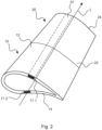
- Figure 2 shows a first rotor blade segment 10 with a first end face 12 and a second rotor blade segment 20 with a second end face 22.
- the first rotor blade segment 10 and the second rotor blade segment 20 are coupled to one another at the end in the longitudinal direction (L).
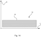
- the first rotor blade segment 10 comprises a blade laminate 14 with a plurality of laminate layers 16 (cf. Figure 14 ).
- the rotor blade 10 further comprises a first reinforcement structure 17.1, which is arranged on the suction side 11.1 of the rotor blade segment 10, and a second reinforcement structure 17.2, which is arranged on the pressure side 11.2.
- the reinforcement structures 17.1, 17.2 extend in the longitudinal direction (L).
- the second rotor blade segment 20 comprises a blade laminate 24 with a plurality of laminate layers (not shown) and a reinforcing structure 27 which extends in the longitudinal direction (L).
- the structure of the second rotor blade segment 20 also corresponds to the structure of the first rotor blade segment 10.
- Figure 3 shows the front end 12 of the first rotor blade segment 10 in a side view.
- the rotor blade segment 10 has a leading edge 18 and a trailing edge 19, which are arranged at a distance from one another transversely to the longitudinal direction (L).
- the reinforcing structure 17.1, 17.2 is embedded in the sheet laminate 14 and runs in the longitudinal direction (L).
- the reinforcing structure 17.1, 17.2 preferably comprises a unidirectional fabric whose fibers are oriented in the longitudinal direction (L).
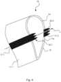
- a plurality of mounting elements 30.1, 30.2 are preferably arranged on the front side 12 in the area of the reinforcing structure 17.1, 17.2.
- the majority of the mounting elements 30.1, 30.2 extend in the longitudinal direction (L).
- the mounting elements 30.1, 30.2 are arranged in the region of the reinforcement structure 17.1, 17.2 of the rotor blade segment at the front end 12.
- the mounting elements 30.1 are on the first reinforcement structure 17.1 and the mounting elements 30.2 are on the second reinforcement structure 17. 2 and in the profile depth direction (Q) (cf. Figure 6 and 7 ) are arranged at a distance from each other.
- mounting elements 30.1, 30.2 are designed to be connected to corresponding mounting elements 40 (cf. Figures 6 to 9 ) of the second rotor blade segment 20 (cf. Figure 2 ) to be coupled.
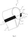
- the embodiment of a rotor blade segment 10' shown differs from that shown in Figure 4 shown embodiment in that the mounting elements 30.1' and 30.2' are arranged adjacent to each other in the profile thickness direction (D) (cf. Figure 10 to 13 ).
- the mounting elements 30.1' are arranged in the area of the reinforcement structure 17.1 on the front side 12 and extend in the longitudinal direction (L).
- the mounting elements 30.2' are arranged in the area of the reinforcement structure 17.2 on the front side 12 and extend in the longitudinal direction (L).
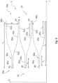
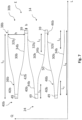
- FIG. 6 to 9 show embodiments of the mounting elements 30a, 30b, 30c, wherein the mounting elements 30a, 30b, 30c are spaced from one another in a plane (E), in particular in the profile depth direction (Q).
- the mounting elements 30a are designed such that a free space is formed between two adjacent mounting elements 30a, into which a corresponding mounting element 40a of the second rotor blade segment 20 (cf. Figure 2 ) is included.
- the mounting elements 40a each have a contact surface 42a pointing upwards in the profile depth direction (Q) according to the present schematic representation and a contact surface 44a pointing downwards.
- Each of the mounting elements 40a is accommodated in the free space of the adjacent mounting elements 30a in such a way that the contact surfaces 42a, 44a are in contact with one of the contact surfaces 32a, 34a of the two adjacent mounting elements 30a.
- An adhesive 50 is applied to the contact surfaces 32a, 34a of the mounting elements 30a and/or the contact surfaces 42a, 44a of the mounting elements 40a, which adhesive bonds the mounting elements 30a of the first rotor blade segment 10 (cf. Figure 1 ) with the mounting elements 40a of the second rotor blade segment 20 (cf. Figure 2 ) is added.
- the assembly elements 30a, 40a are formed on the front side of the sheet laminate 14, 24, in particular integrally, so that the fiber orientation of the layers of the sheet laminate corresponds to the fiber orientation of the layers of the assembly elements 30a, 40a and vice versa.
- the assembly elements 30a, 40a can be integrally formed on the reinforcement structures 17.1, 17.2 (cf. Figure 4 , 5 ) must be trained.
- the mounting elements 30a each have an end section 36a in which the distance between the contact surfaces 32a, 34a is constant.
- the mounting elements 30a also each have a laminate-side section in which the distance between the contact surfaces 32a, 34a is constant.
- the contact surfaces 32a, 34a thus run at least partially parallel to the fiber orientation of the sheet laminate 14 (cf. Figure 2 ) or the reinforcement structure 17 (cf. Figure 4 ).
- the distance between the contact surfaces 42a, 44a in the profile depth direction (Q) of the mounting elements 40a corresponds to the course of the contact surfaces 32a, 34a.
- the minimum distance between any two of the contact surfaces 32a, 34a and 42a, 44a is defined by the distance (b).
- the maximum distance between any two of the contact surfaces 32a, 34a and 42a, 44a is defined by the distance (h).
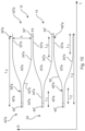
- FIG. 7 shows a further embodiment of the mounting elements 30b, 40b according to the invention.
- the embodiment shown differs from the ones in Figure 6 shown embodiment in that the respective distance of the contact surfaces 32b, 34b in the profile depth direction (Q) of the mounting elements 30b decreases at the end in such a way that each of the contact surfaces 32b, 34b in the end section 36b is in contact with a laminate layer 16 (cf. Figure14 ) of the sheet laminate 14 (cf. Figure 2 ) or, a plane extending parallel to the laminate layers asymptotically approaches in the profile depth direction (Q). Furthermore, the distance between the contact surfaces in the profile depth direction (Q) on the laminate side increases in such a way that each of the contact surfaces 32b, 34b in the laminate-side section 38b adapts to the fiber orientation of the sheet laminate 14 or the reinforcement structure 17 (cf. Figure 2 ) asymptotically in the profile depth direction (Q).
- the distance between the contact surfaces 42b, 44b in the profile depth direction (Q) of the mounting elements 40a corresponds to the course of the contact surfaces 32b, 34b.
- the minimum distance between two of the contact surfaces 32a, b, c and 34a, b, c as well as 42a, b, c and 44a, b, c is defined by the distance (b).
- the maximum distance between two of the contact surfaces 32a, b, c and 34a, b, c as well as 42a, b, c and 44a, b, c is defined by the distance (h).
- the laminate-side section 38a, b has a longitudinal extension L 1 and the end-side section 36a, b has a longitudinal extension L 2 , wherein the longitudinal extension L 1 is greater than the longitudinal extension L 2 .
- the laminate-side section 48a, 48b has a longitudinal extension L 1 and the end-side section 46a, 46b has a longitudinal extension L 2 , wherein the longitudinal extension L 1 is greater than the longitudinal extension L 2 .
- a tolerance range 39, 49 is formed in each case, by which material-related and production-related shape and position deviations are compensated.
- the mounting elements 30b, 40b are integrally formed on the reinforcing structure 17.1, 17.2 and the end-side section 36a, 46a runs so smoothly into the laminate-side section 38a, 48a that the adhesive tensions of the adhesive 50 are reduced.
- the design of the embodiment otherwise corresponds to that in Figure 7 shown embodiment.
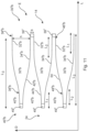
- the Figure 9 The embodiment of the mounting elements 30c, 40c shown differs from that in Figure 8 shown embodiment in that the mounting elements 30, 40 are arranged both spaced apart or adjacent to each other in the profile depth direction (Q) and offset from each other in the longitudinal direction (L).
- the mounting elements 30c have a according to the illustration in Figure 9 in the profile depth direction (Q) pointing upwards, and further a second contact surface 34c pointing downwards in the profile depth direction (Q), wherein the upper contact surface 32c is shorter than the lower contact surface 34c.
- the second mounting elements 40c each have a Figure 9 in the profile depth direction (Q) pointing upwards contact surface 42c, and further a second contact surface 44c pointing downwards in the profile depth direction (Q), wherein the upper contact surface 42c is longer than the lower contact surface 44c.
- the mounting elements 30c, 40c are arranged offset from one another in the longitudinal direction (L), so that stresses are distributed along the longitudinal direction (L) and stress peaks are avoided.
- FIGS. 10 to 13 show embodiments of the mounting elements 30'a, 30'b, 30'c, wherein the mounting elements 30'a, 30'b, 30'c are spaced apart from one another in a plane (E), in particular in the profile thickness direction (D).
- the mounting elements 30 ⁇ a are designed in such a way that a free space is formed between two adjacent mounting elements 30 ⁇ a, into which a corresponding mounting element 40 ⁇ a of the second rotor blade segment 20 (cf. Figure 2 ) is included.
- the mounting elements 40 ⁇ a each have a contact surface 42'a pointing upwards in the profile thickness direction (D) according to the present schematic representation and a contact surface 44 ⁇ a pointing downwards.
- Each of the mounting elements 40 ⁇ a is accommodated in the free space of the adjacent mounting elements 30 ⁇ a in such a way that the contact surfaces 42 ⁇ a, 44 ⁇ a are in contact with one of the contact surfaces 32 ⁇ a, 34 ⁇ a of the two adjacent mounting elements 30 ⁇ a.
- An adhesive 50 is applied to the contact surfaces 32 ⁇ a, 34 ⁇ a of the mounting elements 30 ⁇ a and/or the contact surfaces 42 ⁇ a, 44 ⁇ a of the mounting elements 40 ⁇ a, which adhesive 50 bonds the mounting elements 30 ⁇ a of the first rotor blade segment 10 (cf. Figure 1 ) with the mounting elements 40 ⁇ a of the second rotor blade segment 20 (cf. Figure 2 ) is added.
- the assembly elements 30'a, 40 ⁇ a are formed on the front side of the sheet laminate 14, 24, in particular integrally, so that the fiber orientation of the layers of the sheet laminate corresponds to the fiber orientation of the layers of the assembly elements 30'a, 40'a and vice versa.
- the assembly elements 30'a, 40 ⁇ a can be integrally formed on the reinforcement structures 17.1, 17.2 (cf. Figure 4 , 5 ) must be trained.
- the mounting elements 30'a each have an end section 36'a in which the distance between the contact surfaces 32 ⁇ a, 34 ⁇ a is constant.
- the mounting elements 30'a further each have a laminate-side section 38'a in which the distance between the contact surfaces 32'a, 34'a is constant.
- the distance between the contact surfaces 42 ⁇ a, 44 ⁇ a in the profile thickness direction (D) of the mounting elements 40 ⁇ a corresponds to the course of the contact surfaces 32 ⁇ a, 34 ⁇ a.
- the contact surfaces 32 ⁇ a, 34 ⁇ a run at least partially parallel to the laminate layers 16 (cf. Figure 14 ) of the sheet laminate 14 (cf. Figure 2 ).
- FIG. 11 and 12 shows a further embodiment of the mounting elements 30 ⁇ b, 40 ⁇ b according to the invention.
- the embodiment shown differs from the ones in Figure 10 shown embodiment in that the respective distance of the contact surfaces 32'b, 34'b in the profile thickness direction (D) of the mounting elements 30'b decreases at the end in such a way that each of the contact surfaces 32'b, 34'b in the end section 36'b is in contact with a laminate layer 16 (cf. Figure14 ) of the sheet laminate 14 (cf. Figure 2 ) or, a plane extending parallel to the laminate layers asymptotically approaches in the profile thickness direction (D). Furthermore, the distance between the contact surfaces in the profile thickness direction (D) on the laminate side increases in such a way that each of the contact surfaces 32 ⁇ b, 34'b in the laminate-side section 38'b is in contact with a laminate layer 16 (cf. Figure 14 ) of the sheet laminate 14 (cf. Figure 2 ) or a plane extending parallel to the laminate layers asymptotically in the profile thickness direction (D).
- the distance between the contact surfaces 42'b, 44 ⁇ b in the profile thickness direction (D) of the mounting elements 40 ⁇ a corresponds to the course of the contact surfaces 32 ⁇ b, 34 ⁇ b.
- the minimum distance between two of the contact surfaces 32 ⁇ a, b, c and 34'a, b, c as well as 42 ⁇ a, b, c and 44'a, b, c is defined by the distance (b).
- the maximum distance between two of the contact surfaces 32a, b, c and 34 ⁇ a, b, c as well as 42 ⁇ a, b, c and 44 ⁇ a, b, c is defined by the distance (h).
- the laminate-side section 38'a, 38 ⁇ b has a longitudinal extension L 1 and the end-side section 36'a, 36 ⁇ b has a longitudinal extension l_ 2 , wherein the longitudinal extension L 1 is greater than the longitudinal extension L 2 .
- the laminate-side section 48'a, 48'b has a longitudinal extension L 1 and the end-side section 46'a, 46'b has a longitudinal extension L 2 , wherein the longitudinal extension L 1 is greater than the longitudinal extension L 2 .
- a tolerance range 39', 49' is formed in each case, by which material-related and production-related shape and position deviations are compensated.
- the mounting elements 30 ⁇ b, 40 ⁇ b are integrally formed on the reinforcing structure 17.1, 17.2 and the end section 36'a, 46 ⁇ a runs so smoothly into the laminate-side section 38 ⁇ a, 48 ⁇ a that the adhesive tensions of the adhesive 50 are reduced.
- the design of the embodiment otherwise corresponds to that in Figure 11 shown embodiment.
- the embodiment of the mounting elements 30 ⁇ c, 40'c shown differs from that in Figure 12 shown embodiment in that the mounting elements 30 ⁇ c, 40 ⁇ c are arranged both spaced apart or adjacent to each other in the profile thickness direction (D) and offset from each other in the longitudinal direction (L).
- the mounting elements 30'c have a according to the illustration in Figure 13 in the profile thickness direction (D) upwardly pointing contact surface 32'c, and furthermore a second contact surface 34'c pointing downwardly in the profile thickness direction (D), wherein the upper contact surface 32'c is shorter than the lower contact surface 34 ⁇ c.
- the second mounting elements 40'c each have a Figure 13 contact surface 42'c pointing upwards in the profile thickness direction (D), and further comprises a second contact surface 44'c pointing downwards in the profile thickness direction (D), wherein the upper contact surface 42'c is longer than the lower contact surface 44 ⁇ c.
- the mounting elements 30'c, 40'c are arranged offset from one another in the longitudinal direction (L), so that stresses are distributed along the longitudinal direction (L) and stress peaks are avoided.
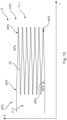
- Figure 14 shows a section of the sheet laminate 14 in a schematic view. According to this view, it is clear that the laminate layers 16 are stacked essentially parallel to one another in the profile thickness direction (D) and are arranged in a plane which runs essentially parallel to the longitudinal direction (L).
- the laminate layers 16 are preferably made of a fiber composite material, wherein undulations arise due to undulations, for example in fabric-reinforced fiber composite materials.
- a laminate layer is understood to mean a layer which extends substantially parallel to the longitudinal direction (L), wherein undulations in the laminate layer due to the fabric structure are within the tolerance range.
- Such a layer structure consisting of laminate layers stacked in the profile thickness direction (D) is equally applicable in the area of the reinforcement structure 17 (cf. Figure 3 and 4 ), whereby the laminate layers are formed from a unidirectional fabric whose fibre orientation runs in the longitudinal direction (L).
Landscapes
- Engineering & Computer Science (AREA)
- Life Sciences & Earth Sciences (AREA)
- Sustainable Development (AREA)
- Sustainable Energy (AREA)
- Chemical & Material Sciences (AREA)
- Combustion & Propulsion (AREA)
- Mechanical Engineering (AREA)
- General Engineering & Computer Science (AREA)
- Wind Motors (AREA)
Claims (15)
- Pale de rotor (108) pour une éolienne (100) avec- une direction longitudinale (L), dans laquelle s'étend la pale de rotor (108),- au moins un premier segment de pale de rotor (10, 10') avec un premier côté frontal (12), et- au moins un deuxième segment de pale de rotor (20) avec un deuxième côté frontal (22), dans laquelle le premier segment de pale de rotor (10, 10') est couplé au deuxième segment de pale de rotor (20) côté frontal dans le sens longitudinal (L),dans laquelle le premier et le deuxième segment de pale de rotor (10, 10', 20) comprennent chacun :-- un stratifié de pale (14, 24) avec une multitude de couches de stratifié (16), lesquelles sont disposées de manière empilée dans une direction d'épaisseur de profilé (D), et-- une multitude d'éléments de montage (30a, 30b, 30c, 30a', 30b', 30'c, 30.1, 30.2, 40a, 40b, 40c, 40a', 40b', 40'c) disposés côté frontal destinés à coupler le premier segment de pale de rotor (10, 10') au deuxième segment de pale de rotor (20),dans laquelle chacun des éléments de montage (30a, 30b, 30c, 30a', 30b', 30'c, 30.1, 30.2, 40a, 40b, 40c, 40a', 40b', 40'c) s'étend dans la direction longitudinale (L) et présente deux surfaces de contact (32a, 32b, 32c, 32'a, 32'b, 32'c, 34a, 34b, 34c, 34'a, 34'b, 34'c, 42a, 42b, 42c, 42'a, 42'b, 42'c, 44a, 44b, 44c, 44'a, 44'b, 44'c), lesquelles sont disposées de manière transversale, en particulier de manière orthogonale, par rapport à la direction longitudinale (L), à une distance les unes par rapport aux autres, qui diminue de manière non linéaire côté extrémité.
- Pale de rotor (108) selon la revendication 1, dans laquelle la multitude d'éléments de montage (30a, 30b, 30c, 30a', 30b', 30'c, 30.1, 30.2, 40a, 40b, 40c, 40a', 40b', 40'c) sont disposés de manière adjacente les uns par rapport aux autres dans un plan (E) de manière orthogonale par rapport à la direction longitudinale (L), et
est réalisé respectivement, entre deux éléments de montage (30a, 30b, 30c, 30a', 30b', 30'c) adjacents, un espace libre, dans lequel un élément de montage (40a, 40b, 40c, 40'a, 40'b, 40'c) correspondant est logé de telle manière que les surfaces de contact (42a, 42b, 42c, 42'a, 42'b, 42'c, 44a, 44b, 44c, 44'a, 44'b, 44'c) de l'élément de montage (40a, 40b, 40c, 40'a, 40'b, 40'c) logé sont en appui avec respectivement une des surfaces de contact (32a, 32b, 32c, 32'a, 32'b, 32'c, 34a, 34b, 34c, 34'a, 34'b, 34'c) des deux éléments de montage (30a, 30b, 30c, 30a', 30b', 30'c) adjacents. - Pale de rotor (108) selon la revendication 2,
dans laquelle les surfaces de contact (42a, 42b, 42c, 42'a, 42'b, 42'c, 44a, 44b, 44c, 44'a, 44'b, 44'c) en appui de l'élément de montage (40, 40a, 40b, 40c, 40, 40'a, 40'b, 40'c) logé et les surfaces de contact (32a, 32b, 32c, 32'a, 32'b, 32'c, 34a, 34b, 34c, 34'a, 34'b, 34'c) des deux éléments de montage (30a, 30b, 30c, 30a', 30b', 30c') adjacents sont reliées les unes aux autres par liaison de matière, en particulier au moyen d'une colle, laquelle est appliquée sur les surfaces de contact (32a, 32b, 32c, 32'a, 32'b, 32'c, 34a, 34b, 34c, 34'a, 34'b, 34'c) des deux éléments de montage adjacents et/ou sur les surfaces de contact (42a, 42b, 42c, 42'a, 42'b, 42'c, 44a, 44b, 44c, 44'a, 44'b, 44'c) de l'élément de montage logé. - Pale de rotor (108) selon l'une quelconque des revendications précédentes,dans laquelle le premier et le deuxième segment de pale de rotor (10, 10', 20) comprennent chacun en outre :- au moins une structure de renforcement (17, 17.1, 17.2, 27) destinée à absorber des forces longitudinales, laquelle s'étend le long du segment de pale de rotor (10, 10', 20) dans le sens longitudinal (L),dans laquelle les éléments de montage (30a, 30b, 30c, 30a', 30b', 30c') sont chacun disposés côté frontal dans la zone de la structure de renforcement (17, 17.1, 17.2) respective, et la structure de renforcement (17, 17.1, 17.2) du premier segment de pale de rotor (10, 10') est couplée à la structure de renforcement (27) du deuxième segment de pale de rotor (20),dans laquelle de préférence la structure de renforcement (17, 17.1, 17.2, 27) présente au moins une couche de stratifié, de préférence une multitude de couches de stratifié, en un tissu unidirectionnel, lequel est orienté dans la direction longitudinale (L).
- Pale de rotor (108) selon l'une quelconque des revendications précédentes,dans laquelle les éléments de montage (30b, 30b', 40b, 40b') présentent une section côté stratifié (38b, 38'b, 48b, 48'b) et une section côté extrémité (36b, 36'b, 46b, 46'b), et le profil des surfaces de contact (32b, 32'b, 34b, 34'b, 42b, 42'b, 44b, 44'b) est défini par une condition marginale tangentielle par rapport à la direction longitudinale (L) dans la section côté stratifié (38b, 38'b, 48b, 48'b) et/ou dans la section côté extrémité (38b, 38'b, 48b, 48'b), et/oudans laquelle les éléments de montage (30a, 30a', 40a, 40a') présentent une section côté stratifié (38a, 38'a, 48a, 48'a) et une section côté extrémité (36a, 36'a, 46a, 46'a), ou présentent la section côté stratifié (38b, 38'b, 48b, 48'b) et la section côté extrémité (36b, 36'b, 46b, 46'b), et la distance des surfaces de contact (32a, 32'a, 34a, 34'a, 42a, 42'a, 44a, 44'a) dans la section côté stratifié (38a, 38'a, 48a, 48'a, 38b, 38'b, 48b, 48'b) et/ou dans la section côté extrémité (36a, 36'a, 46a, 46'a, 36a, 36'a, 46a, 46'a) est constante au moins par endroits.
- Pale de rotor (108) selon la revendication 5,dans laquelle les surfaces de contact (32'b, 34'b, 42'b, 44'b) sont espacées les unes par rapport aux autres dans la direction d'épaisseur de profilé (D) et les surfaces de contact (32'b, 34'b, 42'b, 44'b) se rapprochent de manière asymptotique côté extrémité d'une couche de stratifié (16) du stratifié de pale (14, 24) ou d'un plan s'étendant de manière parallèle aux couches de stratifié (16), oudans laquelle les surfaces de contact (32'b, 34'b, 42'b, 44'b) sont espacées les unes par rapport aux autres dans la direction d'épaisseur de profilé (D), et la distance est constante au moins par endroits et les surfaces de contact (32'b, 34'b, 42'b, 44'b) s'étendent par endroits de manière parallèle aux couches de stratifié (16) du stratifié de pale (14, 24) et/ou de la structure de renforcement (17, 17.1, 17.2, 27).
- Pale de rotor (108) selon au moins l'une quelconque des revendications 5 à 6,
dans laquelle la section côté stratifié (38a, 38'a, 48a, 48'a, 38b, 38'b, 48b, 48'b) présente une extension longitudinale L1 et la section côté extrémité (36a, 36'a, 46a, 46'a, 36b, 36'b, 46b, 46'b) présente une extension longitudinale L2, et l'extension longitudinale L1 est plus grande que l'extension longitudinale L2, dans laquelle une zone de tolérance est réalisée de manière à jouxter la section côté stratifié. - Pale de rotor (108) selon la revendication 6, dans laquelle les éléments de montage (30a, 30b, 40a, 40b, 30'a, 30'b, 40'a, 40b') présentent une extension longitudinale L3, et le rapport entre une distance maximale (h) des surfaces de contact (32a, 32b, 32c, 32'a, 32'b, 32'c, 34a, 34b, 34c, 34'a, 34'b, 34'c, 42a, 42b, 42c, 42'a, 42'b, 42'c, 44a, 44b, 44c, 44'a, 44'b, 44'c) et l'extension longitudinale L3 est ≥ 5h.
- Pale de rotor (108) selon la revendication 7 ou 8,dans laquelle l'extension longitudinale L3 est une première extension longitudinale L3.1 d'au moins un premier élément de montage (30.1, 40.1), etle premier et le deuxième segment de pale de rotor (10, 10', 20) comprennent en outre respectivement au moins un deuxième élément de montage (30.2) avec une deuxième extension longitudinale L3.2, laquelle est plus grande que l'extension longitudinale L3.1.
- Pale de rotor (108) selon l'une quelconque des revendications précédentes,dans laquelle la multitude d'éléments de montage (30a, 30b, 30c, 30'a, 30'b, 30'c, 40a, 40b, 40c, 40'a, 40'b, 40'c) sont disposés de manière décalée dans la direction longitudinale (L) ou de manière espacée les uns par rapport aux autres, et/oudans laquelle la distance (b) minimale des surfaces de contact (32a, 32b, 32c, 32'a, 32'b, 32'c, 34a, 34b, 34c, 34'a, 34'b, 34'c, 42a, 42b, 42c, 42'a, 42'b, 42c, 44a, 44b, 44c, 44'a, 44'b, 44'c) par rapport aux deux éléments de montage (30a, 30b, 30c, 30'a, 30'b, 30'c, 40a, 40b, 40c, 40'a, 40'b, 40'c) est ≥ 1,5 mm.
- Pale de rotor (108) selon l'une quelconque des revendications 4 à 10,
dans laquelle la structure de renforcement (17, 17.1, 17.2, 27) comprend un longeron et/ou un renforcement de bord d'attaque et/ou un renforcement de bord de fuite. - Eolienne (100) avec au moins une pale de rotor selon au moins l'une quelconque des revendications précédentes 1 - 11.
- Procédé de fabrication d'une pale de rotor d'une éolienne (100), comprenant les étapes :- de fourniture d'un premier segment de pale de rotor (10, 10'),- de fourniture d'au moins un deuxième segment de pale de rotor (20),- de mise en prise de la multitude d'éléments de montage (30a, 30b, 30c, 30a', 30b', 30c') disposés côté frontal du premier segment de pale de rotor (10, 10') avec les éléments de montage (40a, 40b, 40c, 40'a, 40'b, 40'c) correspondants du deuxième segment de pale de rotor (20),dans lequel le premier segment de pale de rotor (10, 10') et le deuxième segment de pale de rotor (20) sont chacun réalisés avec- un côté frontal (12),
dans lequel le segment de pale de rotor (10, 10') peut être couplé dans la direction longitudinale côté frontal à un segment de pale de rotor (20) adjacent,- un stratifié de pale (14) avec une multitude de couches de stratifié (16), lesquelles sont empilées dans une direction d'épaisseur de profilé (D), et- une multitude d'éléments de montage (30a, 30b, 30c, 30a', 30b', 30c', 30.1, 30.2, 40a, 40b, 40c, 40a', 40b', 40'c) disposés côté frontal, lesquels peuvent être amenés en prise avec une multitude d'éléments de montage (30a, 30b, 30c, 30a', 30b', 30'c, 30.1, 30.2, 40a, 40b, 40c, 40a', 40b', 40'c) correspondants du segment de pale de rotor adjacent pour coupler le premier segment de pale de rotor (10, 10') au deuxième segment de pale de rotor (20),dans lequel chacun des éléments de montage (30a, 30b, 30c, 30a', 30b', 30'c, 30.1, 30.2, 40a, 40b, 40c, 40a', 40b', 40'c) s'étend dans la direction longitudinale (L) et présente deux surfaces de contact (32a, 32b, 32c, 32'a, 32'b, 32'c, 34a, 34b, 34c, 34'a, 34'b, 34'c, 42a, 42b, 42c, 42'a, 42'b, 42'c, 44a, 44b, 44c, 44'a, 44'b, 44'c), lesquelles sont disposées de manière transversale, en particulier de manière orthogonale, par rapport à la direction longitudinale (L), à une distance, les unes par rapport aux autres, qui diminue de manière non linéaire côté extrémité. - Procédé selon la revendication 13,dans lequel la multitude d'éléments de montage (30a, 30b, 30c, 30a', 30b', 30c', 40a, 40b, 40c, 40'a, 40'b, 40'c) sont disposés de manière adjacente les uns par rapport aux autres de manière orthogonale à la direction longitudinale (L) dans un plan (E), et un espace libre est formé respectivement entre deux éléments de montage (30a, 30b, 30c, 30a', 30b', 30c', 40a, 40b, 40c, 40'a, 40'b, 40'c) adjacents, etdans lequel l'étape de la mise en prise comprend en outre :- le logement respectivement d'un des éléments de montage (40a, 40b, 40c, 40'a, 40'b, 40'c) dans chacun des espaces libres si bien que les surfaces de contact (42a, 42b, 42c, 42'a, 42'b, 42'c, 44a, 44b, 44a, 44'a, 44'b, 44'c) de chaque élément de montage (40a, 40b, 40c, 40'a, 40'b, 40'c) logé sont en appui avec respectivement une des surfaces de contact (32a, 32b, 32c, 32'a, 32'b, 32'c, 34a, 34b, 34c, 34'a, 34'b, 34'c) des deux éléments de montage (30a, 30b, 30c, 30a', 30b', 30c') adjacents.
- Procédé selon la revendication 14,
dans lequel le procédé comprend en outre, avant l'étape de la mise en prise, l'étape :- d'application d'une colle sur chacune des surfaces de contact (32a, 32b, 32c, 32'a, 32'b, 32'c, 34a, 34b, 34c, 34'a, 34'b, 34'c, 42a, 42b, 42c, 42'a, 42'b, 42'c, 44a, 44b, 44c, 44'a, 44'b, 44'c) du premier (10, 10') et/ou du deuxième segment de pale de rotor (20) .
Applications Claiming Priority (2)
| Application Number | Priority Date | Filing Date | Title |
|---|---|---|---|
| DE102019118317.0A DE102019118317A1 (de) | 2019-07-05 | 2019-07-05 | Rotorblatt für eine Windenergieanlage, Rotorblattsegment, Windenergieanlage und Verfahren zur Herstellung eines Rotorblattes |
| PCT/EP2020/066345 WO2021004723A1 (fr) | 2019-07-05 | 2020-06-12 | Pale de rotor pour une éolienne, segment de pale de rotor, éolienne et procédé pour la fabrication d'une pale de rotor |
Publications (3)
| Publication Number | Publication Date |
|---|---|
| EP3994351A1 EP3994351A1 (fr) | 2022-05-11 |
| EP3994351B1 true EP3994351B1 (fr) | 2024-08-21 |
| EP3994351C0 EP3994351C0 (fr) | 2024-08-21 |
Family
ID=71094361
Family Applications (1)
| Application Number | Title | Priority Date | Filing Date |
|---|---|---|---|
| EP20732871.7A Active EP3994351B1 (fr) | 2019-07-05 | 2020-06-12 | Pale de rotor pour une éolienne, segment de pale de rotor, éolienne et procédé pour la fabrication d'une pale de rotor |
Country Status (5)
| Country | Link |
|---|---|
| US (1) | US11802544B2 (fr) |
| EP (1) | EP3994351B1 (fr) |
| CN (1) | CN114080497B (fr) |
| DE (1) | DE102019118317A1 (fr) |
| WO (1) | WO2021004723A1 (fr) |
Families Citing this family (2)
| Publication number | Priority date | Publication date | Assignee | Title |
|---|---|---|---|---|
| EP4160004B1 (fr) * | 2021-09-29 | 2025-05-14 | Vestas Wind Systems A/S | Pale d'éolienne modulaire |
| CN116081312A (zh) * | 2022-04-20 | 2023-05-09 | 湖南探索机械科技有限公司 | 一种旋转阀 |
Family Cites Families (13)
| Publication number | Priority date | Publication date | Assignee | Title |
|---|---|---|---|---|
| DK175562B1 (da) * | 2002-03-19 | 2004-12-06 | Lm Glasfiber As | Vindmöllevinge med kulfibertip |
| ATE534817T1 (de) * | 2004-06-30 | 2011-12-15 | Vestas Wind Sys As | Aus zwei getrennten teilen hergestellte windturbinenflügel |
| US20110158788A1 (en) * | 2008-08-31 | 2011-06-30 | Vestas Wind Systems A/S | A sectional blade |
| EP2444660A4 (fr) * | 2009-07-09 | 2013-05-22 | Mitsubishi Heavy Ind Ltd | Pale de turbine eolienne et procede de fabrication de celle-ci |
| DK2534373T3 (da) | 2010-02-10 | 2014-08-04 | Vestas Wind Sys As | Sektionsopdelt vinge |
| DK3019741T3 (en) * | 2013-07-09 | 2018-03-26 | Vestas Wind Sys As | WINDMILL LIVES WITH SECTIONS THAT ARE ASSEMBLED |
| PT3099477T (pt) * | 2014-01-31 | 2021-03-11 | Lm Wp Patent Holding As | Pá de turbina eólica com transição de fibra melhorada |
| WO2015181401A1 (fr) * | 2014-05-29 | 2015-12-03 | Nabrawind Sl | Raccordement par vissage pour pale modulaire |
| US11181093B2 (en) * | 2014-06-18 | 2021-11-23 | Siemens Gamesa Renewable Energy A/S | Rotor blade with noise reduction means |
| EP3144526A1 (fr) * | 2015-09-16 | 2017-03-22 | Siemens Aktiengesellschaft | Connexion pour une pale de rotor de turbine éolienne segmentée |
| US10605227B2 (en) * | 2017-04-12 | 2020-03-31 | General Electric Company | Segmented wind turbine rotor blade with welded joint |
| EP3406424B1 (fr) * | 2017-05-22 | 2021-04-28 | Ratier-Figeac SAS | Pale d'aéronef et procédés de formation et de réparation d'une pale d'aéronef |
| EP3874140A1 (fr) * | 2018-11-01 | 2021-09-08 | General Electric Company | Raccordement en biseau pour une pale de rotor d'éolienne |
-
2019
- 2019-07-05 DE DE102019118317.0A patent/DE102019118317A1/de not_active Withdrawn
-
2020
- 2020-06-12 WO PCT/EP2020/066345 patent/WO2021004723A1/fr not_active Ceased
- 2020-06-12 EP EP20732871.7A patent/EP3994351B1/fr active Active
- 2020-06-12 CN CN202080049113.4A patent/CN114080497B/zh not_active Withdrawn - After Issue
- 2020-06-12 US US17/624,807 patent/US11802544B2/en active Active
Also Published As
| Publication number | Publication date |
|---|---|
| CN114080497A (zh) | 2022-02-22 |
| WO2021004723A1 (fr) | 2021-01-14 |
| DE102019118317A1 (de) | 2021-01-07 |
| US20220260049A1 (en) | 2022-08-18 |
| CN114080497B (zh) | 2024-08-23 |
| EP3994351A1 (fr) | 2022-05-11 |
| EP3994351C0 (fr) | 2024-08-21 |
| US11802544B2 (en) | 2023-10-31 |
Similar Documents
| Publication | Publication Date | Title |
|---|---|---|
| EP3469212B1 (fr) | Rotor pour éolienne, pale de rotor pour éolienne, manchon et procédé de montage d'un rotor | |
| DE102007020339B4 (de) | Rotorblatt für eine Windturbine | |
| EP1914383B1 (fr) | Aube de soufflante en matériau composite | |
| DE2621914C2 (de) | Hubschrauber-Heckrotor | |
| EP0057272B1 (fr) | Pale d'hélice en construction de coquille | |
| EP2363599B2 (fr) | Pale de rotor pour une éolienne, éolienne et procédé de fabrication d'une pale de rotor | |
| EP2184440B1 (fr) | Arbre d'une turbine à gaz | |
| EP3701107B1 (fr) | Console annulaire destinée à la contrainte externe d'un segment de tour, système de contrainte externe d'une tour hybride, section de tour d'une tour hybride, tour hybride, éolienne et procédé de montage d'un système de contrainte externe pour une tour hybride | |
| EP1840372A2 (fr) | Assemblage d'une pale d'éolienne | |
| EP3396155B1 (fr) | Pale de rotor d'une éolienne, procédé de fabrication d'une telle pale, et utilisation d'un élément de liaison | |
| EP3994351B1 (fr) | Pale de rotor pour une éolienne, segment de pale de rotor, éolienne et procédé pour la fabrication d'une pale de rotor | |
| EP2434143B1 (fr) | Pale de rotor ou segment d'une pale de rotor pour une éolienne | |
| DE102014100814B4 (de) | Turmbauwerk für eine Windenergieanlage | |
| DE202013007886U1 (de) | Windenergieanlagenrotorblatt mit passiver Lastreduzierung | |
| DE102017106875B4 (de) | Windkraftanlage und Verfahren zu dessen Montage | |
| WO2011110605A2 (fr) | Pale de rotor d'éolienne | |
| EP3551438B1 (fr) | Membrure de bord de fuite d'une pale de rotor d'une installation éolienne, pale de rotor et procédé de fabrication d'une membrure de bord de fuite | |
| EP3808972B1 (fr) | Raccordement entre les segments longitudinaux d'une pale de rotor du rotor d'une éolienne | |
| DE102019128487A1 (de) | Verbindung zwischen Längssegmenten eines Rotorblattes des Rotors einer Windenergieanlage | |
| EP3356669B1 (fr) | Pale de rotor d'éolienne et éolienne | |
| WO2015110580A1 (fr) | Mât haubané pour une éolienne ayant une résistance à la torsion élevée | |
| EP3844384B1 (fr) | Rotor comprenant une pale de rotor, éolienne et procédé d'optimisation d'une éolienne | |
| EP3775532B1 (fr) | Pale de rotor d'éolienne et éolienne | |
| EP3710691B1 (fr) | Attachement d'une pale d'éolienne avec le moyeu d'une éolienne | |
| EP3469211B1 (fr) | Pale de rotor, éolienne et procédé de montage et de fabrication d'une pale de rotor |
Legal Events
| Date | Code | Title | Description |
|---|---|---|---|
| STAA | Information on the status of an ep patent application or granted ep patent |
Free format text: STATUS: UNKNOWN |
|
| STAA | Information on the status of an ep patent application or granted ep patent |
Free format text: STATUS: THE INTERNATIONAL PUBLICATION HAS BEEN MADE |
|
| PUAI | Public reference made under article 153(3) epc to a published international application that has entered the european phase |
Free format text: ORIGINAL CODE: 0009012 |
|
| STAA | Information on the status of an ep patent application or granted ep patent |
Free format text: STATUS: REQUEST FOR EXAMINATION WAS MADE |
|
| 17P | Request for examination filed |
Effective date: 20220207 |
|
| AK | Designated contracting states |
Kind code of ref document: A1 Designated state(s): AL AT BE BG CH CY CZ DE DK EE ES FI FR GB GR HR HU IE IS IT LI LT LU LV MC MK MT NL NO PL PT RO RS SE SI SK SM TR |
|
| DAV | Request for validation of the european patent (deleted) | ||
| DAX | Request for extension of the european patent (deleted) | ||
| GRAP | Despatch of communication of intention to grant a patent |
Free format text: ORIGINAL CODE: EPIDOSNIGR1 |
|
| STAA | Information on the status of an ep patent application or granted ep patent |
Free format text: STATUS: GRANT OF PATENT IS INTENDED |
|
| INTG | Intention to grant announced |
Effective date: 20240326 |
|
| GRAS | Grant fee paid |
Free format text: ORIGINAL CODE: EPIDOSNIGR3 |
|
| GRAA | (expected) grant |
Free format text: ORIGINAL CODE: 0009210 |
|
| STAA | Information on the status of an ep patent application or granted ep patent |
Free format text: STATUS: THE PATENT HAS BEEN GRANTED |
|
| AK | Designated contracting states |
Kind code of ref document: B1 Designated state(s): AL AT BE BG CH CY CZ DE DK EE ES FI FR GB GR HR HU IE IS IT LI LT LU LV MC MK MT NL NO PL PT RO RS SE SI SK SM TR |
|
| REG | Reference to a national code |
Ref country code: GB Ref legal event code: FG4D Free format text: NOT ENGLISH |
|
| REG | Reference to a national code |
Ref country code: CH Ref legal event code: EP |
|
| REG | Reference to a national code |
Ref country code: IE Ref legal event code: FG4D Free format text: LANGUAGE OF EP DOCUMENT: GERMAN |
|
| REG | Reference to a national code |
Ref country code: DE Ref legal event code: R096 Ref document number: 502020008956 Country of ref document: DE |
|
| U01 | Request for unitary effect filed |
Effective date: 20240903 |
|
| U07 | Unitary effect registered |
Designated state(s): AT BE BG DE DK EE FI FR IT LT LU LV MT NL PT RO SE SI Effective date: 20240916 |
|
| PG25 | Lapsed in a contracting state [announced via postgrant information from national office to epo] |
Ref country code: NO Free format text: LAPSE BECAUSE OF FAILURE TO SUBMIT A TRANSLATION OF THE DESCRIPTION OR TO PAY THE FEE WITHIN THE PRESCRIBED TIME-LIMIT Effective date: 20241121 |
|
| PG25 | Lapsed in a contracting state [announced via postgrant information from national office to epo] |
Ref country code: GR Free format text: LAPSE BECAUSE OF FAILURE TO SUBMIT A TRANSLATION OF THE DESCRIPTION OR TO PAY THE FEE WITHIN THE PRESCRIBED TIME-LIMIT Effective date: 20241122 Ref country code: PL Free format text: LAPSE BECAUSE OF FAILURE TO SUBMIT A TRANSLATION OF THE DESCRIPTION OR TO PAY THE FEE WITHIN THE PRESCRIBED TIME-LIMIT Effective date: 20240821 |
|
| PG25 | Lapsed in a contracting state [announced via postgrant information from national office to epo] |
Ref country code: IS Free format text: LAPSE BECAUSE OF FAILURE TO SUBMIT A TRANSLATION OF THE DESCRIPTION OR TO PAY THE FEE WITHIN THE PRESCRIBED TIME-LIMIT Effective date: 20241221 |
|
| PG25 | Lapsed in a contracting state [announced via postgrant information from national office to epo] |
Ref country code: HR Free format text: LAPSE BECAUSE OF FAILURE TO SUBMIT A TRANSLATION OF THE DESCRIPTION OR TO PAY THE FEE WITHIN THE PRESCRIBED TIME-LIMIT Effective date: 20240821 |
|
| PG25 | Lapsed in a contracting state [announced via postgrant information from national office to epo] |
Ref country code: ES Free format text: LAPSE BECAUSE OF FAILURE TO SUBMIT A TRANSLATION OF THE DESCRIPTION OR TO PAY THE FEE WITHIN THE PRESCRIBED TIME-LIMIT Effective date: 20240821 Ref country code: RS Free format text: LAPSE BECAUSE OF FAILURE TO SUBMIT A TRANSLATION OF THE DESCRIPTION OR TO PAY THE FEE WITHIN THE PRESCRIBED TIME-LIMIT Effective date: 20241121 |
|
| PG25 | Lapsed in a contracting state [announced via postgrant information from national office to epo] |
Ref country code: RS Free format text: LAPSE BECAUSE OF FAILURE TO SUBMIT A TRANSLATION OF THE DESCRIPTION OR TO PAY THE FEE WITHIN THE PRESCRIBED TIME-LIMIT Effective date: 20241121 Ref country code: PL Free format text: LAPSE BECAUSE OF FAILURE TO SUBMIT A TRANSLATION OF THE DESCRIPTION OR TO PAY THE FEE WITHIN THE PRESCRIBED TIME-LIMIT Effective date: 20240821 Ref country code: NO Free format text: LAPSE BECAUSE OF FAILURE TO SUBMIT A TRANSLATION OF THE DESCRIPTION OR TO PAY THE FEE WITHIN THE PRESCRIBED TIME-LIMIT Effective date: 20241121 Ref country code: IS Free format text: LAPSE BECAUSE OF FAILURE TO SUBMIT A TRANSLATION OF THE DESCRIPTION OR TO PAY THE FEE WITHIN THE PRESCRIBED TIME-LIMIT Effective date: 20241221 Ref country code: HR Free format text: LAPSE BECAUSE OF FAILURE TO SUBMIT A TRANSLATION OF THE DESCRIPTION OR TO PAY THE FEE WITHIN THE PRESCRIBED TIME-LIMIT Effective date: 20240821 Ref country code: GR Free format text: LAPSE BECAUSE OF FAILURE TO SUBMIT A TRANSLATION OF THE DESCRIPTION OR TO PAY THE FEE WITHIN THE PRESCRIBED TIME-LIMIT Effective date: 20241122 Ref country code: ES Free format text: LAPSE BECAUSE OF FAILURE TO SUBMIT A TRANSLATION OF THE DESCRIPTION OR TO PAY THE FEE WITHIN THE PRESCRIBED TIME-LIMIT Effective date: 20240821 |
|
| PG25 | Lapsed in a contracting state [announced via postgrant information from national office to epo] |
Ref country code: SM Free format text: LAPSE BECAUSE OF FAILURE TO SUBMIT A TRANSLATION OF THE DESCRIPTION OR TO PAY THE FEE WITHIN THE PRESCRIBED TIME-LIMIT Effective date: 20240821 |
|
| PG25 | Lapsed in a contracting state [announced via postgrant information from national office to epo] |
Ref country code: CZ Free format text: LAPSE BECAUSE OF FAILURE TO SUBMIT A TRANSLATION OF THE DESCRIPTION OR TO PAY THE FEE WITHIN THE PRESCRIBED TIME-LIMIT Effective date: 20240821 |
|
| PG25 | Lapsed in a contracting state [announced via postgrant information from national office to epo] |
Ref country code: SK Free format text: LAPSE BECAUSE OF FAILURE TO SUBMIT A TRANSLATION OF THE DESCRIPTION OR TO PAY THE FEE WITHIN THE PRESCRIBED TIME-LIMIT Effective date: 20240821 |
|
| U20 | Renewal fee for the european patent with unitary effect paid |
Year of fee payment: 6 Effective date: 20250521 |
|
| PLBE | No opposition filed within time limit |
Free format text: ORIGINAL CODE: 0009261 |
|
| STAA | Information on the status of an ep patent application or granted ep patent |
Free format text: STATUS: NO OPPOSITION FILED WITHIN TIME LIMIT |
|
| PGFP | Annual fee paid to national office [announced via postgrant information from national office to epo] |
Ref country code: GB Payment date: 20250620 Year of fee payment: 6 |
|
| 26N | No opposition filed |
Effective date: 20250522 |
|
| REG | Reference to a national code |
Ref country code: CH Ref legal event code: H13 Free format text: ST27 STATUS EVENT CODE: U-0-0-H10-H13 (AS PROVIDED BY THE NATIONAL OFFICE) Effective date: 20260127 |
|
| PG25 | Lapsed in a contracting state [announced via postgrant information from national office to epo] |
Ref country code: MC Free format text: LAPSE BECAUSE OF FAILURE TO SUBMIT A TRANSLATION OF THE DESCRIPTION OR TO PAY THE FEE WITHIN THE PRESCRIBED TIME-LIMIT Effective date: 20240821 |
|
| PG25 | Lapsed in a contracting state [announced via postgrant information from national office to epo] |
Ref country code: IE Free format text: LAPSE BECAUSE OF NON-PAYMENT OF DUE FEES Effective date: 20250612 |
|
| PG25 | Lapsed in a contracting state [announced via postgrant information from national office to epo] |
Ref country code: CH Free format text: LAPSE BECAUSE OF NON-PAYMENT OF DUE FEES Effective date: 20250630 |