EP3994355B1 - System zur offshore-stromerzeugung - Google Patents
System zur offshore-stromerzeugung Download PDFInfo
- Publication number
- EP3994355B1 EP3994355B1 EP20835116.3A EP20835116A EP3994355B1 EP 3994355 B1 EP3994355 B1 EP 3994355B1 EP 20835116 A EP20835116 A EP 20835116A EP 3994355 B1 EP3994355 B1 EP 3994355B1
- Authority
- EP
- European Patent Office
- Prior art keywords
- mast
- buoyancy body
- rotor
- power generating
- generating system
- Prior art date
- Legal status (The legal status is an assumption and is not a legal conclusion. Google has not performed a legal analysis and makes no representation as to the accuracy of the status listed.)
- Active
Links
Images


Classifications
-
- B—PERFORMING OPERATIONS; TRANSPORTING
- B63—SHIPS OR OTHER WATERBORNE VESSELS; RELATED EQUIPMENT
- B63B—SHIPS OR OTHER WATERBORNE VESSELS; EQUIPMENT FOR SHIPPING
- B63B43/00—Improving safety of vessels, e.g. damage control, not otherwise provided for
- B63B43/02—Improving safety of vessels, e.g. damage control, not otherwise provided for reducing risk of capsizing or sinking
-
- F—MECHANICAL ENGINEERING; LIGHTING; HEATING; WEAPONS; BLASTING
- F03—MACHINES OR ENGINES FOR LIQUIDS; WIND, SPRING, OR WEIGHT MOTORS; PRODUCING MECHANICAL POWER OR A REACTIVE PROPULSIVE THRUST, NOT OTHERWISE PROVIDED FOR
- F03D—WIND MOTORS
- F03D13/00—Assembly, mounting or commissioning of wind motors; Arrangements specially adapted for transporting wind motor components
- F03D13/20—Arrangements for mounting or supporting wind motors; Masts or towers for wind motors
- F03D13/25—Arrangements for mounting or supporting wind motors; Masts or towers for wind motors specially adapted for offshore installation
-
- F—MECHANICAL ENGINEERING; LIGHTING; HEATING; WEAPONS; BLASTING
- F03—MACHINES OR ENGINES FOR LIQUIDS; WIND, SPRING, OR WEIGHT MOTORS; PRODUCING MECHANICAL POWER OR A REACTIVE PROPULSIVE THRUST, NOT OTHERWISE PROVIDED FOR
- F03D—WIND MOTORS
- F03D80/00—Details, components or accessories not provided for in groups F03D1/00 - F03D17/00
- F03D80/50—Maintenance or repair
-
- B—PERFORMING OPERATIONS; TRANSPORTING
- B63—SHIPS OR OTHER WATERBORNE VESSELS; RELATED EQUIPMENT
- B63B—SHIPS OR OTHER WATERBORNE VESSELS; EQUIPMENT FOR SHIPPING
- B63B35/00—Vessels or similar floating structures specially adapted for specific purposes and not otherwise provided for
- B63B35/44—Floating buildings, stores, drilling platforms, or workshops, e.g. carrying water-oil separating devices
- B63B2035/4433—Floating structures carrying electric power plants
- B63B2035/446—Floating structures carrying electric power plants for converting wind energy into electric energy
-
- E—FIXED CONSTRUCTIONS
- E02—HYDRAULIC ENGINEERING; FOUNDATIONS; SOIL SHIFTING
- E02B—HYDRAULIC ENGINEERING
- E02B17/00—Artificial islands mounted on piles or like supports, e.g. platforms on raisable legs or offshore constructions; Construction methods therefor
- E02B2017/0091—Offshore structures for wind turbines
-
- F—MECHANICAL ENGINEERING; LIGHTING; HEATING; WEAPONS; BLASTING
- F03—MACHINES OR ENGINES FOR LIQUIDS; WIND, SPRING, OR WEIGHT MOTORS; PRODUCING MECHANICAL POWER OR A REACTIVE PROPULSIVE THRUST, NOT OTHERWISE PROVIDED FOR
- F03D—WIND MOTORS
- F03D7/00—Controlling wind motors
- F03D7/02—Controlling wind motors the wind motors having rotation axis substantially parallel to the air flow entering the rotor
- F03D7/04—Automatic control; Regulation
- F03D7/042—Automatic control; Regulation by means of an electrical or electronic controller
-
- F—MECHANICAL ENGINEERING; LIGHTING; HEATING; WEAPONS; BLASTING
- F05—INDEXING SCHEMES RELATING TO ENGINES OR PUMPS IN VARIOUS SUBCLASSES OF CLASSES F01-F04
- F05B—INDEXING SCHEME RELATING TO WIND, SPRING, WEIGHT, INERTIA OR LIKE MOTORS, TO MACHINES OR ENGINES FOR LIQUIDS COVERED BY SUBCLASSES F03B, F03D AND F03G
- F05B2240/00—Components
- F05B2240/90—Mounting on supporting structures or systems
- F05B2240/93—Mounting on supporting structures or systems on a structure floating on a liquid surface
-
- F—MECHANICAL ENGINEERING; LIGHTING; HEATING; WEAPONS; BLASTING
- F05—INDEXING SCHEMES RELATING TO ENGINES OR PUMPS IN VARIOUS SUBCLASSES OF CLASSES F01-F04
- F05B—INDEXING SCHEME RELATING TO WIND, SPRING, WEIGHT, INERTIA OR LIKE MOTORS, TO MACHINES OR ENGINES FOR LIQUIDS COVERED BY SUBCLASSES F03B, F03D AND F03G
- F05B2240/00—Components
- F05B2240/90—Mounting on supporting structures or systems
- F05B2240/95—Mounting on supporting structures or systems offshore
-
- Y—GENERAL TAGGING OF NEW TECHNOLOGICAL DEVELOPMENTS; GENERAL TAGGING OF CROSS-SECTIONAL TECHNOLOGIES SPANNING OVER SEVERAL SECTIONS OF THE IPC; TECHNICAL SUBJECTS COVERED BY FORMER USPC CROSS-REFERENCE ART COLLECTIONS [XRACs] AND DIGESTS
- Y02—TECHNOLOGIES OR APPLICATIONS FOR MITIGATION OR ADAPTATION AGAINST CLIMATE CHANGE
- Y02E—REDUCTION OF GREENHOUSE GAS [GHG] EMISSIONS, RELATED TO ENERGY GENERATION, TRANSMISSION OR DISTRIBUTION
- Y02E10/00—Energy generation through renewable energy sources
- Y02E10/70—Wind energy
- Y02E10/72—Wind turbines with rotation axis in wind direction
-
- Y—GENERAL TAGGING OF NEW TECHNOLOGICAL DEVELOPMENTS; GENERAL TAGGING OF CROSS-SECTIONAL TECHNOLOGIES SPANNING OVER SEVERAL SECTIONS OF THE IPC; TECHNICAL SUBJECTS COVERED BY FORMER USPC CROSS-REFERENCE ART COLLECTIONS [XRACs] AND DIGESTS
- Y02—TECHNOLOGIES OR APPLICATIONS FOR MITIGATION OR ADAPTATION AGAINST CLIMATE CHANGE
- Y02E—REDUCTION OF GREENHOUSE GAS [GHG] EMISSIONS, RELATED TO ENERGY GENERATION, TRANSMISSION OR DISTRIBUTION
- Y02E10/00—Energy generation through renewable energy sources
- Y02E10/70—Wind energy
- Y02E10/727—Offshore wind turbines
Definitions
- the present invention relates to a system for offshore power generation utilizing wind for generating power.
- the system comprises a mast with a wind turbine in a hinged installation on a floating buoyancy body.
- an offshore power generating system comprising:
- the present invention relates to a method for on board loading and preparing the mast with installed rotor into operation on a buoyancy body.
- floating wind turbines designed so that the waves of the sea surface affect the relative position of the wind turbine to the least possible extent, in order to utilize the energy of the wind in the best possible way.
- the necessary buoyancy for carrying the unit is distributed to one or more uniform, or different, subsea bodies below the sea surface to be connected to a platform above the sea surface, with associated mast and wind turbine, for structures providing the least possible contact with the sea surface.
- Various buoyancy bodies consist for example of one permanently anchored cylinder with a fixedly mounted/installed mast with a rotatable wind turbine, three cylinders wherein the mast is either located on one of the cylinders or located in the center of three cylinders, permanently anchored with 3-4 anchors distributed at intervals of 90-120°.
- Such fixed anchoring does not allow the buoyancy body, and thus the wind turbine, to rotate into the wind direction, whereupon the wind turbine itself must be equipped with rotating devices on top of the mast to control the wind turbine so that it turns up into the wind as the wind changes direction.
- Buoyancy bodies with wind turbines on fixed mast requires installation at still wind conditions by means of lifting tools requiring high power and high lifting height.
- wind turbine and mast are installed on the buoyancy body in an upright, vertical position, the installation can be transported to desired location for anchoring and commissioning.
- Masts of prior art has cylindrical cross section in order for the wind to attack the fixed anchored unit from all directions. This results in unnecessary strength and stability forces, or drag forces on the unit, which creates high turbulence in the air flow at the rear of where the wind hits the mast. This means that the propeller blades of the wind turbine must be mounted/installed on the wind side and thus be rigid, with associated large weight in order to avoid deformations of the propeller blades in strong wind.
- Units with small contact surfaces to the sea surface will have a large weight load per unit area of the contact surface and therefore be sensitive to weight changes and lack the ability to withstand inclining forces from in strong wind or other external impacts.
- the load capacity is therefore limited and complicated by the need of fixed ballast to achieve the necessary righting moment.
- the survivability will also in other critical situations, such as leakages in the buoyancy body or collisions with floating objects, deteriorate or cease.
- Scaling up the production of floating wind turbines is achieved by increasing the number of units arranged in a pattern known from land and shallow coastal water. Such arrangements tend to have major environmental impact and will, for example, be a threat to bird populations, interference in the seabed by buried anchoring systems and power and signal cables will further have an impact on marine life and thus also the fishing industry. The required area will also be a hindrance for example the shipping traffic.
- US2007138021 shows a plurality of wind turbines arranged on a framework of a ship.
- the framework is supported by a shaft forming a hinged joint to the deck of the ship and has one or more counterweights connected to the shaft.
- the counterweight is used to rotate the framework with wind turbines between a horizontal and vertical position.
- the ship may be formed in order for the counterweight to be over or below the water surface when the framework is in vertical position.
- GB2269138 A shows a barge for typically loading of ships or other heavy installations.
- the barge has a hull which may be totally submerged and where the barge is provided with means for stabilizing the hull when submerged.
- the barge has typically stabilizing spuds/tension legs at the side of the barge being anchored to the sea bed, and to ensure stability during ballasting and deballasting during submerging and raising of the hull.
- the submerging/raising is controlled by ballasting of tanks in the hull of the barge.
- WO2014116185 A1 shows an offshore facility comprising a floating platform, for example a ship, with a plurality of wind turbines.
- the floating platform may be provided with ballast tanks for stabilizing offshore.
- the floating platform may be turned, or the wind turbines may be turned about their vertical axis to provide maximum exposure to the wind.
- a turret mooring system together with a propulsion system allows the offshore facility to make optimal use of the wind by rotating the offshore facility about the turret and rotate the wind turbines about their axis.
- WO 02073032 A1 shows a floating wind power generation plant with a single point mooring system fixed to the sea floor whereupon the floating wind power generation plant can be rotated about.
- the floating plant has a plurality of wind power generation units disposed thereon.
- wind turbine is used to describe an entity utilizing the kinetic energy of the wind to produce power.
- the wind turbine comprises at least one wing rotatably arranged on a hub.
- the wind acts on the wing and puts this into a rotational motion.
- the wind turbine is usually arranged on a mast of a certain length, wherein the wind turbine itself is placed on the highest point of the mast.
- the wind turbine can also be arranged on other suitable units.
- biomass will in the following be used to describe a device contributing to the turbine itself being at the desired height above the water surface and the vessel.
- vertical position will in the following be used to describe the mast being in an upraised position for normal operating position or normal working position.
- the term includes that the mast may be inclined in relation to the vertical plane, until about nine degrees in an aft slanted direction.
- buoyancy body is used to describe the vessel on which the wind turbine is to be installed.
- the buoyancy body can take different shapes, however, in this document it shall essentially be formed as a ship's hull.
- the ship's hull shall take the form of sinusoidal water lines as known from the applicant's own US patent no. US 8,726,822 B1 , wherein the aft end is extra wide in relation to other known ship form.
- the hull of sinusoidal water lines is characterized of being very stable, and able to operate in extreme weather condition without significantly affecting the operations.
- forward is that side of the buoyancy body that is pointing forward into the wind direction, opposite of astern. This side usually has a shape that brakes the waves so that the water is pushed past and along the sides of the buoyancy body.
- stern is the planar or slightly convex surface transverse of the longitudinal direction of the buoyancy body and is that end of the buoyancy body which should generally point backwards and lie leeward of the wind direction. Also known as the transom stern of the ship.
- longitudinal position is used to describe the buoyancy body from the side in longitudinal direction, bow and stern pointing in each direction.
- Another object is to provide an offshore power generation system that can be easily relocated between locations.
- It is further an object to provide an offshore power generation system comprising a buoyancy body installed with a mast mounted with a wind turbine, wherein the mast mounted with a wind turbine can be guided between a normal working or operating position or different positions for on-board loading, survival and maintenance, regardless of location.
- Another object is to provide a system enabling transport of an offshore power generating system comprising a buoyancy body installed with a mast mounted with a wind turbine, where the system can be transported between locations with mast with mounted wind turbine in horizontal position.
- Another object is to provide a system enabling location independent maintenance of a wind turbine on a mast installed on a buoyancy body.
- Yet another object of the present invention is to enable boarding of an operator on a buoyancy body with a wind turbine on a mast when wind turbine and mast is in both horizontal and normal operating position.
- a further object is to provide a buoyancy body enabling dimensional increase of mast and wind turbine compared to the prior art without having to increase the dimensions of the buoyancy body accordingly due to the characteristics of the hull.
- a further object of the invention is to provide a solution in which the lifting power of the vessel and its position in relation to the buoyancy of the vessel, as well as the center of gravity are such that the effect of the movement of the ship and motion characteristic is optimal and as small as possible.
- Another object of the present invention is to provide an anchoring system enabling automatically and/or controlled rotation of a buoyancy body in optimal direction relative to wind direction such that this is optimal with respect to the wind direction at any time.
- Yet another object of the invention is to provide a system for wind turbine on a mast located on a buoyancy body, where the buoyancy body has sufficient volume with space for transformers, converters, rectifiers, control equipment, battery and other necessary equipment to process generated energy and energy storage.
- Another object of the present invention is to provide a mast for a wind turbine where the effect of the forces acting on the mast, and which may affect the flow conditions of the blades on the turbine itself, is eliminated or at least significantly reduced.
- a further object of the present invention is to provide a buoyancy body with a wind turbine on a mast being stable also in rough sea.
- the present invention is thus related to an offshore power generating system comprising;
- the center of buoyancy of the buoyancy body lies in a point 1/4 or less of the total length of the buoyancy body from the aft end of the buoyancy body.
- the shape of the buoyancy body in the horizontal plane can preferably be circumscribed by a triangle, where the buoyancy body has maximum width at the aft end.
- the shape of the buoyancy body is defined by a draft corresponding to the significant wave height in the sea state for which it is designed.
- the rotor comprises a wind turbine enclosed by an aerodynamically designed wind turbine housing mounted/installed on the mast.
- the wind turbine housing may further comprise a water ballast tank.
- the mast comprises following mast positions; an operating position, an on-board loading and maintenance position and a survival position.
- the mast In normal operating position with the wings of the rotor in the vertical plane, the mast forms an angle ⁇ relative to vertical plane, where the angle ⁇ is 0-15 degrees, preferably between 6-12 degrees, most preferably 9 degrees, pointing astern from the buoyancy body.
- the mast in survival position In the on-board loading and maintenance position the mast is with the wings of the rotor in the horizontal plane, the mast in survival position is with the wings of the rotor 45-50 degrees astern of the buoyancy body from the vertical plane.
- the offshore power generating system comprises one or more devices for rotating the mast with wind turbine between different positions.
- the device for rotating the mast comprises rope means, winches and/or hydraulic cylinders on the foundation of the mast or in a well in the buoyancy body, where the rope means may comprise fiber rope, wire, chain, etc. and/or hydraulic actuators for adjusting or changing the positions of the mast.
- the restraint mechanism comprises a plurality of hydraulically operated shear bolts arranged at the lower part of the mast foot.
- Mast with rotor maintains approximate operating position by means of one or more dampening devices for maneuvering the mast for compensation of the pitch motions of the buoyancy body.
- One or more dampening devices comprises a unit for maneuvering of the mast, where the unit for maneuvering of the mast is controlled by a control unit receiving signals from sensors, e.g. wave sensors, wind sensors, etc., and where the control unit activates the dampening devices for maneuvering of the mast in order to maintain the mast in as stable operating position as possible.
- the unit for maneuvering the mast comprises hydraulic cylinders for compensating for the pitch motions of the buoyancy body.
- a device for keeping the buoyancy body towards the wind comprises an anchoring system arranged at the bow of the buoyancy body and possible thrusters at least at the aft end of the buoyancy body.
- the rotatable support of the mast is retained by at least one support stand placed aft on the buoyancy body.
- the support stands comprise at least one leg with an aerodynamic cross section anchored in the buoyancy body where the rotational support comprises a bearing housing arranged on top of the support stands.
- the lower part of the mast in its normal operating position is arranged in a separate well in the hull of the buoyancy body.
- Devices for rotating the mast with the wind turbine between the various positions can also or in addition also be arranged in the well.
- the well may comprise the restraint mechanism.
- the present invention is thus related to a method for loading and commissioning of the mast with mounted rotor on-board the buoyancy body of the offshore power generating system.
- the method comprising the following steps;
- the offshore power generating system comprises an anchoring point forward the buoyancy body. This reduces, among other things, extensive interference with the seabed which is required at several anchoring points.
- the system can easily be connected to and from the bottom anchoring and easily moved between different locations. This is enhanced by the fact that the mast with mounted/ installed wind turbine is pivotally arranged in the buoyancy body, whereby the mast can be further rotated between different positions between vertical and horizontal position of turbine blades irrespectively of location and that the buoyancy body is designed as a ship hull with low draft.
- the mast is supported and connected with the buoyancy body aft on the buoyancy body and in operating position the mast slanting/inclining about 9 degrees aft.
- the propeller blades in operating position are parallel to the vertical plane.
- the position of the mast is closely related to the center of gravity of the buoyancy body, where the rotation of the buoyancy body's pitching movements occurs, in order to avoid coupling between rotation and vertical motions. If the mast had been placed mid-ships in the buoyancy body, the mast would, in addition to rotation, have experienced undesired vertical motions.
- An astern position of mast is also convenient when loading the mast onto the buoyancy body.
- a stronger, directional stabilizing moment for the buoyancy body is obtained by placing the wind turbine as far away from the turret /anchorage point as possible.
- the propeller blades which, depending on their rotational position, are in the wind shadow because of the mast, get, because of the inclination of the mast, increased distance to the portion of the mast lying in front of the blades, and thus reduced influence of the wind shadow and the associated turbulence behind the mast.
- the positioning of the wind turbine housing at the mast top and that the mast may comprise a bend astern, can further increase the distance and reduce the effect.
- the mast has different structure above and below the rotary shaft taking into account the inflow conditions of the wind of the propeller blades, where the mast above the rotary shaft has an aerodynamic profile reducing turbulence and the wind shadow of the propeller blades and the mast below the rotary shaft may allow for different design to take into account the strength conditions and vibration and/or oscillation phenomena.
- the mast connects the wind turbine with the buoyancy body in a continuous structure whereby the mast foot is primarily firmly fixed to a well in the buoyancy body when in an upright operating position.
- the connection is loosened for maneuvering to a new desired position.
- the mast with fixed turbine is mainly rotated to operating position at on-board loading into the buoyancy body for transport to destination. Simple devices enable rotation of the mast for rotation and maneuvering the mast to desired positions even at destination.
- a movable rig such as a barge, can be transported offshore to the power generating system to assist in, for example, service and maintenance operations so that the mast with the mounted/ installed turbine can rest thereon.
- the mast with permanently installed turbine can also be released from its fixed connection for maneuvering in order to maintain the propeller blades as close to the vertical plane as possible accounting for the pitching motions of the buoyancy body due to waves.
- passive and/or active dampening devices such as hydraulic cylinders, water, springs etc. to reduce the pitching/heave angles of the mast relative to the pitching angles of the buoyancy body and thus maintain turbine production. If the pitching motions become too large due to large incoming waves, the electricity production can be reduced and possibly stopped by slowing down the rotation of the turbine blades.
- the wind turbine housing may comprise a water ballast tank.
- the natural periods of rolling and pitching due to wave motions increase when the inertial radius of the platform increases.
- With appropriate weight in the wind turbine housing with a large distance to the center of rotation, an increase of the natural periods is achieved, further away from the most frequent wave periods, which will give more operating hours.
- Solution with water ballast tank is possible due to the high stability of the platform.
- the active and passive dampening devices can advantageably be placed in a well in the buoyancy body, preferably a closed well.
- a well in opposite to the open deck, allows for a stable connection of the mast foot and a protective room for equipment for the maneuvering device of the mast.
- the well should not be open to sea but could be filled and emptied by the bilge and ballast system of the buoyancy body.
- the propeller With increased pitching/heave motions, the propeller can be exposed to no inflow of wind or perhaps opposite wind and will thus work as an engine and not a generator.
- the ship itself can be a wave sensor, and by measuring the pitching/heave angle for incoming waves, further incoming waves can be predicted. From the instantaneous measured pitching/heave angle of the buoyancy body, acceptable waves can be filtered out and when a given limit is exceeded, a computer can activate the maneuvering unit so that the mast prepares for the expected incoming waves. The turbine will then be able to continue production even in rougher sea.
- Figure 1 shows prior art of wind turbines arranged on a frame on a ship, as mentioned in US 2007138021 , showing several wind turbines 130 arranged on a frame on a buoyancy body 110 here represented by a ship.
- the frame or the mast 140 is supported by a bearing housing 121 on the ship forming a hinged link to the ship deck 116 and has one or more counterweights connected to the shaft.
- the counterweight is used to rotate the frame 120 with wind turbines 130 between a horizontal and vertical position.
- the ship 130 may be designed so that the counterweight is above or below the water surface 120 when the frame is in vertical position.
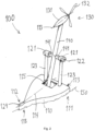
- FIG. 2 shows schematically and in perspective one possible embodiment of a system for offshore power generation 100.
- the system 100 shows a buoyancy body 110 at a sea surface 150 with mounted/ installed mast 140 with a wind turbine 130 in normal operating position, inclined about 9 degrees astern.
- the well permits a stable attachment of the mast foot, as well a protected room for equipment for maneuvering, not shown, of the mast 115. It is not open to sea, not shown in the figure, and can be filled and emptied by the bilge and ballast system of the buoyancy body.
- the description on figure 4b below gives a more detailed description of the maneuvering equipment.
- the mast 140 can be rotated to achieve desired positions for normal operating position, on-board loading position, maintenance position and survival position respectively, further discussed in connection with figure 6b below.
- the mast 140 rotates about an axis of rotation 122, which is at the center of gravity of the mast 140.
- the mast 140 is at this point mounted/ installed on bearing shafts 141, which extend on either side of the mast 140.
- the bearing shafts 141 of the mast 140 are supported between two bearing housings 121 mounted/ installed on two support stands 123 astern of the buoyancy body.
- FIG 3a shows schematically a perspective of one embodiment of the buoyancy body 110 in a normal operating state.
- the buoyancy body 110 has an approximately triangular base shape with a wide stern 113 where a center of buoyancy 120 lies in a distance from the stern 113 of approximately 1/4 or less of the length of the buoyancy body 110, and a contact surface with the sea 150 where the center of floatation 119 has a distance from the stern 113 of approximately 1/3 of the length of the buoyancy body 110, or less.
- the buoyancy body 110 is closest to the wind direction equipped with a single point anchoring system 124 known from the offshore industry.
- the anchoring system 124 provides for holding the buoyancy body 110 up into the wind and is preferably arranged at the bow of the buoyancy body 110, in addition, thrusters arranged at the aft end 111 of the buoyancy body can further assist keeping the buoyancy body 110 up into the wind.
- the buoyancy body 110 is equipped with two symmetrically positioned support stands 123 astern with legs comprising aerodynamically shaped cross sections and with shared bearing housing 121 on the top forming a rotational axis 122 for the mast 140.
- the bearing housings 121 are installed with a common horizontal center line 122 perpendicular to the buoyancy body's center plane 114, at a height above the deck adapted to the purpose of the support stands 123 which, among other things, may be to receive offshore structures such as masts 140 with wind turbines 130.
- Figure 3a shows two support stands 123 protruding up and are approximately perpendicular to the buoyancy body 110 and the sea surface 150 at calm sea.
- the support stands 123 are not limited to protrude up in this direction, each of which may also project slanted from the buoyancy body 110.
- Each support stand 123 is further shown to comprise of a single strut, but each of them may also be combined with one or more slanted/inclined struts for stiffening the structure.
- the buoyancy body's 110 contact with the energy-rich sea surface 150 is made large enough so that an irregular and a position variable energy distribution can be integrated by the horizontal area of the buoyancy body 110, so that the energy distribution of the waves below the buoyancy body 110 can be cancelled and the buoyancy body's 110 response on the existing forces thereby are reduced.
- the size of the contact surface has a low weight load per area unit, typically about 3-4 metric tonnes/m 2 , so that no problems with loading capacity, trim, stability and survivability will arise and will thus give the buoyancy body 110 a draft allowing docking at offshore ship yards and docking in existing dry docks.
- the contact surface between the buoyancy body 110 and the sea may assume different variants 10 of the base triangle where the desired location of the water line center of floatation 119 is fulfilled as shown in figures 3b and 3c .
- the shape of the buoyancy body 100 in the horizontal plane will influence the distribution of the buoyancy along the length L of the buoyancy body 110, which also will assume an approximate triangular shape, with the largest cross-sectional area close to the stern 113.
- the sole purpose of the buoyancy body 110 is to support the wind turbine 130, and can, above the sea surface 150, instead of a conventional deck, be replaced by a super structure 116 shaped so that incoming sea is allowed to move away from the buoyancy body 110 and to excite as little motions as possible.
- the underwater hull 117 of the buoyancy body 110 has a shape adapted to the load of the waves upon which the super structure 116 can be shaped approximately similar to the underwater hull 117 with the keel pointing upwards, as shown in a cross section 11 in figure 3d .
- the super structure 116 takes the waves so that the hull gets less motions by the waves rolling over rather than colliding with a bow. This increases the survivability of the buoyancy body 110 by better tolerating the encounter with the waves.
- the buoyancy body's 100 volume gives sufficient room for transformers, converters, rectifiers and control equipment to process the generating energy to a desired format and groups of battery for storage of energy, preferably located in the well 115 of the buoyancy body 110, other relevant, protecting locations on the deck of the buoyancy body are relevant locations.
- the mast foot is installed with fixing devices for maneuvering and or dampening of the mast and the pendulum movements of the mast and possibly brake plates for that incident when lower end of the mast is submerged in water in a well at the aft part of the vessel, to reduce angular movements about the rotational axis 122 of the mast.
- the well 115 may be separated from the surrounding sea so that also the volume of the well contributes to the buoyancy and stability corresponding to a tank on-board the vessel.
- the mast 140 with the wind turbine 130 is balanced about the rotational axis 122 so that it in installed position on the buoyancy body 110, easily may be rotated to desired positions for different purposes.
- the well 115 may be air-filled and the dampening devices may be a suitable releasable suspension system.
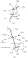
- Figure 5 shows a longitudinal section in the center plane with the mast 140 in different positions 140a, 140b, 140c rotated about the rotational axis in the bearing housing 121.
- the mast 140 in normal operational position is indicated at 140a, on-board loading and maintenance position 140b, and survival position 140c. In all these positions the mast 140 with the wind turbine 130 will keep its mass center of gravity in the rotational axis 122, whereby the maneuvering of the mast 140 to the different positions 140a, 140b, 140c can be performed with suitable, known devices.
- the foot of the mast 140 is connected in the vertical plane of the buoyancy body 110 with suitable passive and/or active dampening devices 160.
- the well 115 may also be filled with sea water so that the brake plates which may be arranged on the mast foot may further contribute to the dampening.
- the relative dampening of the mast 140 relative to the unit's total angular deflection can be controlled by a control unit (not shown).
- a plurality of hydraulic cylinders (not shown) can act as dampening means 160.
- the mast 140 In the on-board loading position 140b, the mast 140 inclines a further 90 degrees astern from normal operating position 140a, the wings 132 lying parallel to the horizontal plane. In the maintenance and survival position 140c the mast 140 inclines 45-50 degrees from normal operating position 140a.
- Mast 140 with wind turbine 130 maintains approximately normal operating position 140a by means of one or more dampening devices 190 for maneuvering of the mast 140 to compensate for heave/pitching motions of the buoyancy body 110.
- the dampening devices will comprise a unit for maneuvering the mast, which is controlled by a control unit receiving signals from sensors, for example wave sensors, wind sensors, etc.. The control unit will activate the dampening devices to maneuver the mast in order to maintain the mast in as stable operating position 140a as possible.
- the unit for maneuvering the mast may comprise hydraulic cylinders to compensate for pitching/heave motions of the buoyancy body.
- FIGS 6a-6c show on-board loading of a mast 140 with wind turbine.
- Mast 140 is in on-board loading position 140b on suitable movable rig 170 either in the form of a movable rig 170 floating at sea, for example a barge, or a movable rig 170 standing ashore.
- suitable movable rig 170 either in the form of a movable rig 170 floating at sea, for example a barge, or a movable rig 170 standing ashore.
- Weight transfer of mast 140 with wind turbine 130 is effected by pumping out water ballast.
- Mast 140 with wind turbine 130, balanced and with center of gravity in the bearing at the shafts 141, is rotated with suitable, known devices to the desired position, normal operating position 140a as shown in figure 6c .
- the mast 140 with wind turbine 130 is held in normal operating position by engaging the retaining mechanism with the mast foot, whereby the retaining mechanism preferably comprises hydraulically operated shear bolts.
- the restraint mechanism is brought out of engagement with the mast foot, whereby activating dampening devices, preferably comprising a given number of hydraulic cylinders, are being activated.
- the mast 140 can be maneuvered by moving the retaining mechanism out of engagement with the mast foot and by known devices the mast can be maneuvered to desired mast positions; operating position 140a, on-board loading and maintenance position 140b, and survival position 140c.
- Table 1 100 Offshore power generating system 110 Buoyancy body 111 Aft end 112 Bow or stem 113 Stern 114 Centre plan of the buoyancy body 115 Well 116 Super structure 117 Underwater hull 118 Forward 119 Center of floatation 120 Center of buoyancy 121 Bearing housing 122 The rotational axis 122 of the mast in the horizontal plane 123 Support stand 124 Anchoring system/point 125 Aerodynamic cross section of the mast 130 Wind turbine/rotor 131 Wind turbine hosing 132 Wing 133 The rotational axis of the wind turbine 140 Mast 140a Mast in normal operating position 140b Mast in on-board loading and maintenance position 140c Mast in survival position 141 The bearing shaft of the mast 150 Sea surface 160 Dampening devices 160' Angular positions
Landscapes
- Engineering & Computer Science (AREA)
- Chemical & Material Sciences (AREA)
- Mechanical Engineering (AREA)
- Combustion & Propulsion (AREA)
- Sustainable Energy (AREA)
- Life Sciences & Earth Sciences (AREA)
- Sustainable Development (AREA)
- General Engineering & Computer Science (AREA)
- Ocean & Marine Engineering (AREA)
- Wind Motors (AREA)
- Control Of Eletrric Generators (AREA)
- Purification Treatments By Anaerobic Or Anaerobic And Aerobic Bacteria Or Animals (AREA)
- Other Liquid Machine Or Engine Such As Wave Power Use (AREA)
Claims (15)
- Offshore-Stromerzeugungssystem (100), umfassend- einen Auftriebskörper (110) in Form eines Rumpfs mit einem Bug (112) und einem hinteren Ende (111);- einen länglichen, aerodynamisch geformten Mast (140), der ausgebildet ist, um von dem Auftriebskörper (110) nach oben zu ragen, und drehbar auf dem Auftriebskörper (110) um eine horizontale Querachse (122) gestützt ist;- einen Rotor, der in einem Ende des Längsmastes (140) für Rotation um eine horizontale Achse gestützt ist, die in Längsrichtung des Auftriebskörpers (110) ausgerichtet ist;- eine Anordnung zum Halten des Auftriebskörpers (110) in einer Position, in der sich der Bug (112) nach oben in Richtung des Windes und der ankommenden Wellen dreht;dadurch gekennzeichnet, dass
die Rotationsstütze des Mastes (140) eine horizontale, quer ausgerichtete Rotationsachse (122) durch den Schwerpunkt des Mastes (140) umfasst, wobei der Schwerpunkt des Mastes (140) in der Mittelebene (114) des Auftriebskörpers (110) vertikal über dem hinteren Ende (111) des Auftriebskörpers (110) liegt, wenn der Auftriebskörper (110) in Betriebsposition bei ruhiger See liegt, und wobei die Rotationsachse (122) der Rotationsstütze des Mastes (140) orthogonal zu der Mittelebene (114) des Auftriebskörpers (110) ist. - Offshore-Stromerzeugungssystem (100) nach Anspruch 1, wobei der Auftriebsmittelpunkt (112) des Auftriebskörpers (110) in einem Punkt von 1/4 oder weniger der Gesamtlänge des Auftriebskörpers (110) von dem hinteren Ende (111) des Auftriebskörpers (110) liegt.
- Offshore-Stromerzeugungssystem (100) nach Anspruch 1 oder 2, wobei die Form des Auftriebskörpers (110) in der horizontalen Ebene durch ein Dreieck umgrenzt ist, wobei der Auftriebskörper (110) an dem hinteren Ende (111) maximale Breite aufweist.
- Offshore-Stromerzeugungssystem (100) nach Anspruch 3, wobei die Form des Auftriebskörpers durch eine Druckbelastung auf die Oberfläche in der Größenordnung von 3-6 metrischen Tonnen/m2, 4-5 metrischen Tonnen/m2 oder 4,5 metrischen Tonnen/m2 auf der vertikalen Projektion des Auftriebskörpers (110) auf der Oberfläche mit einem Blockkoeffizienten von etwa 0,35 definiert ist, wobei der Blockkoeffizient durch die Formel CB=V/L*B*T gegeben ist, wobei V ein Unterwasservolumen des Auftriebskörpers (110) ist, L die Länge des Auftriebskörpers (110) ist, B die maximale Breite des Auftriebskörpers (110) ist und T der Tiefgang des Auftriebskörpers ist.
- Offshore-Stromerzeugungssystem (100) nach den Ansprüchen 1 bis 4, wobei die Form des Auftriebskörpers (110) durch einen der signifikanten Wellenhöhe entsprechenden Tiefgang in dem Seegang definiert ist, für den er ausgebildet ist.
- Offshore-Stromerzeugungssystem (100) nach einem der vorstehenden Ansprüche, wobei der Rotor eine Windturbine (130) umfasst, die von einem aerodynamisch ausgebildeten Windturbinengehäuse (131) umschlossen ist, das an dem Mast (140) montiert/installiert ist; und wobei das Windturbinengehäuse (131) einen Wasserballasttank umfasst.
- Offshore-Stromerzeugungssystem (100) nach einem der vorstehenden Ansprüche, wobei der Mast zwischen den folgenden Positionen rotierbar ist: einer Betriebsposition (140a), einer On-Board-Lade- und Wartungsposition (140b) und einer Überlebensposition (140c), und wobei der Mast (140) mit dem Rotor in normaler Betriebsposition (140a) und mit den Flügeln des Rotors in der vertikalen Ebene einen Winkel α mit der vertikalen Ebene bildet, wobei der Winkel α 0-15 Grad, zwischen 6-12 Grad oder 9 Grad beträgt und von dem Auftriebskörper nach achtern zeigt, oder
wobei der Mast (140) in der On-Board-Lade- und Wartungsposition (140b) mit den Flügeln (132) des Rotors in der horizontalen Ebene ist, der Mast (140) in der Überlebensposition (140c) mit den Flügeln (132) des Rotors 45-50 Grad achtern von dem Auftriebskörper von der vertikalen Ebene ist. - Offshore-Stromerzeugungssystem (100) nach Anspruch 6 oder 7, wobei das Offshore-Stromerzeugungssystem (110) eine oder mehrere Vorrichtungen zum Rotieren des Mastes (140) mit Windturbine (130) zwischen verschiedenen Positionen (140a-c) umfasst, wobei die Vorrichtung zum Rotieren des Masts (140) ein Seilmittel, Winden und/oder Hydraulikzylinder auf dem Fundament des Masts (140) umfasst, und wobei das Seilmittel ein Faserseil, einen Draht, eine Kette usw. und/oder hydraulische Stellantriebe zum Einstellen oder Ändern der Positionen (140a-c) des Masts (140) umfassen kann.
- Offshore-Stromerzeugungssystem (100) nach Anspruch 7 oder 8, wobei der Mast (140) mit Rotor vorübergehend in der Betriebsposition (140a) durch einen lösbaren Rückhaltemechanismus arretiert ist, und
wobei der Rückhaltemechanismus eine Vielzahl von hydraulisch betätigten Scherbolzen umfasst, die an dem unteren Teil des Mastfußes angeordnet sind. - Offshore-Stromerzeugungssystem (100) nach einem der Ansprüche 1 bis 8, wobei der Mast mit Rotor die ungefähre Betriebsposition (140a) mittels einer oder mehrerer Dämpfungsvorrichtungen (160) zum Manövrieren des Masts (140) zur Kompensation der Nickbewegungen des Auftriebskörpers (110) hält, und
wobeieine oder mehrere Dämpfungsvorrichtungen eine Einheit zum Manövrieren des Mastes (140) umfassen, wobei die Einheit zum Manövrieren des Masts (140) durch eine Steuereinheit gesteuert wird, die Signale von Sensoren, beispielsweise Wellensensoren, Windsensoren usw., empfängt, und wobei die Steuereinheit dazu konfiguriert ist, die Dämpfungsvorrichtungen (160) zum Manövrieren des Masts (140) zu aktivieren, um den Mast (140) in einer möglichst stabilen Betriebsposition (140a) zu halten, undwobei die Einheit zum Manövrieren des Mastes (140) Hydraulikzylinder zum Kompensieren der Nickbewegungen des Auftriebskörpers (110) umfasst. - Offshore-Stromerzeugungssystem (100) nach einem der vorstehenden Ansprüche, wobei die Vorrichtung zum Halten des Auftriebskörpers (110) in Windrichtung ein an dem Bug (112) des Auftriebskörpers (110) angeordnetes Ankersystem und möglicherweise Triebwerke zumindest an dem hinteren Ende (111) des Auftriebskörpers (110) umfasst.
- Offshore-Stromerzeugungssystem (100) nach einem der vorstehenden Ansprüche, wobei die Rotationsstütze des Mastes (140) von mindestens einem Stützständer (123) gehalten wird, der achtern von dem Auftriebskörper (100) angeordnet ist, wobei die Stützständer (123) mindestens ein Bein mit einem aerodynamischen Querschnitt umfassen, das in dem Auftriebskörper (110) verankert ist, wobei die Rotationsstütze ein Lagergehäuse (121) umfasst, das oben auf den Stützständern (123) angeordnet ist.
- Offshore-Stromerzeugungssystem (100) nach einem der Ansprüche 8 bis 12, wobei der untere Teil des Mastes (140) in seiner normalen Betriebsposition (140a) in einem separaten Schacht (115) in dem Rumpf des Auftriebskörpers (110) angeordnet ist, und wobei die Vorrichtungen zum Rotieren des Mastes (140) mit der Windturbine (130) zwischen den verschiedenen Positionen (140a-c) ebenfalls oder zusätzlich auch in dem Schacht (115) angeordnet sind, und wobei der Schacht (115) den Rückhaltemechanismus umfasst.
- Verfahren zum Laden und Inbetriebnehmen des Mastes (140) mit Rotor an Bord des Auftriebskörpers (110) des Offshore-Stromerzeugungssystems (100) nach einem der Ansprüche 1 bis 13, wobei das Verfahren durch die folgenden Schritte gekennzeichnet ist:- Platzieren des Mastes (140) mit Rotor in horizontaler On-Board-Ladeposition (140b), platziert auf einem beweglichen Rigg (170) auf einem Kai/an Land oder auf einer schwimmenden Einheit auf dem Wasser;- Positionieren des mit Wasserballast gefüllten Auftriebskörpers (110) neben dem beweglichen Rigg (170) zum Aufnehmen des Mastes (140);- Abpumpen von Wasserballast zur Gewichtsverlagerung des Mastes (140) mit Rotor;- Rotieren des Mastes (140) mit Rotor, mit Schwerpunkt in der Stütze, in die gewünschten Positionen des Mastes (140); wobei die gewünschten Positionen eine Betriebsposition (140a), eine On-Board- und Wartungsposition (140b) oder eine Überlebensposition (140c) sind,wobei der Mast (140) mit Rotor in der Betriebsposition (140a) mit den Flügeln des Rotors in der vertikalen Ebene ist und einen Winkel α mit der vertikalen Ebene bildet, wobei der Winkel α 0-15 Grad beträgt und achtern von dem Auftriebskörper zeigt, der Mast (140) mit Rotor in der On-Board- und Wartungsposition (140b) mit den Flügeln (132) des Rotors in der horizontalen Ebene ist, der Mast (140) mit Rotor in der Überlebensposition (140c) mit den Flügeln (132) des Rotors 45-50 Grad von der vertikalen Ebene achtern von dem Auftriebskörper ist.
- Verfahren nach Anspruch 14, wobei das Verfahren ferner die folgenden Schritte umfasst;- Eingreifen einer Vielzahl von hydraulisch betätigten Scherbolzen mit dem Mastfuß in der normalen Betriebsposition (140a) des Mastes (140) zum Verriegeln des Mastes (140) in der normalen Betriebsposition (140a); und- Bewegen der hydraulischen Scherbolzen aus dem Eingriff mit dem Mastfuß, wodurch eine Vielzahl von Hydraulikzylindern aktiviert wird, um die Nickbewegungen des Auftriebskörpers (110) zu kompensieren, wobei die Hydraulikzylinder die Winkelpositionen (160') des Mastes (140) anpassen, um die Position des Mastes (140) relativ zu der horizontalen Ebene bei ruhiger See +/- 2-4 Grad der normalen Betriebsposition (140a) des Mastes (140) bei ruhiger See zu halten; oder- Bewegen der hydraulischen Scherbolzen aus dem Eingriff mit dem Mastfuß, um den Mast (140) in die gewünschte Position des Mastes (140) zu manövrieren; die normale Betriebsposition (140a), die On-Board- und Wartungsposition (140b) und die Überlebensposition (140c).
Applications Claiming Priority (2)
| Application Number | Priority Date | Filing Date | Title |
|---|---|---|---|
| NO20190831A NO345559B1 (no) | 2019-07-02 | 2019-07-02 | System for offshore kraftgenerering |
| PCT/NO2020/050180 WO2021002759A1 (en) | 2019-07-02 | 2020-06-25 | System for offshore power generation |
Publications (3)
| Publication Number | Publication Date |
|---|---|
| EP3994355A1 EP3994355A1 (de) | 2022-05-11 |
| EP3994355A4 EP3994355A4 (de) | 2023-08-02 |
| EP3994355B1 true EP3994355B1 (de) | 2025-04-30 |
Family
ID=74101359
Family Applications (1)
| Application Number | Title | Priority Date | Filing Date |
|---|---|---|---|
| EP20835116.3A Active EP3994355B1 (de) | 2019-07-02 | 2020-06-25 | System zur offshore-stromerzeugung |
Country Status (6)
| Country | Link |
|---|---|
| US (1) | US11891977B2 (de) |
| EP (1) | EP3994355B1 (de) |
| JP (1) | JP7569108B2 (de) |
| CN (1) | CN114041012A (de) |
| NO (1) | NO345559B1 (de) |
| WO (1) | WO2021002759A1 (de) |
Families Citing this family (2)
| Publication number | Priority date | Publication date | Assignee | Title |
|---|---|---|---|---|
| US12539947B2 (en) | 2021-08-04 | 2026-02-03 | Deep Reach Technology, Inc. | Installation system and method for an offshore wind turbine |
| WO2025184470A1 (en) | 2024-02-28 | 2025-09-04 | Syrovy George J | Floating wind turbine with passive pitch correction |
Family Cites Families (19)
| Publication number | Priority date | Publication date | Assignee | Title |
|---|---|---|---|---|
| JPS59120788A (ja) | 1982-12-27 | 1984-07-12 | Kodo Keiun | 風力発電装置 |
| JPS6067786A (ja) * | 1983-09-22 | 1985-04-18 | Hayashibara Takeshi | 風車 |
| US4590718A (en) * | 1984-02-13 | 1986-05-27 | Grumman Aerospace Corporation | Portable, adjustable structure and method of erecting same |
| JPS61275587A (ja) | 1985-05-30 | 1986-12-05 | Mitsubishi Heavy Ind Ltd | 風車鉄塔 |
| GB9215905D0 (en) | 1992-07-27 | 1992-09-09 | Downham Ralph | Barge |
| DK1366290T3 (da) | 2001-03-08 | 2007-12-10 | Ishikawajima Harima Heavy Ind | Flydende offshore-vindkraftanlæg |
| US7293960B2 (en) * | 2003-10-23 | 2007-11-13 | Shigeyuki Yamamoto | Power generation assemblies, and apparatus for use therewith |
| US20070138021A1 (en) * | 2005-12-15 | 2007-06-21 | Nicholson David W | Maritime hydrogen generation system |
| NO329736B1 (no) | 2009-09-22 | 2010-12-13 | Roar Ramde | Skip |
| WO2011051804A1 (en) | 2009-10-27 | 2011-05-05 | Windflip As | Partially submersible wind turbine transport vessel |
| NO331392B1 (no) * | 2010-03-05 | 2011-12-12 | Ingenium As | Fremgangsmate og anordning for installasjon av en offshore vindturbinanordning |
| FR2970696B1 (fr) * | 2011-01-25 | 2013-02-08 | Ideol | Corps flottant annulaire |
| NO20111329A1 (no) * | 2011-09-29 | 2012-10-08 | Windel As | Flytende vindmølle |
| DK2948365T3 (en) | 2013-01-25 | 2018-03-26 | Tmt Pte Ltd | OFFSHORE INSTALLATIONS |
| DE102013111115B3 (de) * | 2013-10-08 | 2015-01-22 | Linnhoff Offshore AG | Schwimmfähige Offshore-Windkraftanlage |
| US9989038B2 (en) * | 2015-12-18 | 2018-06-05 | Gerald L. Barber | Wind turbine with improved safety features |
| US10788016B2 (en) * | 2017-05-10 | 2020-09-29 | Gerald L. Barber | Transitioning wind turbine |
| CN107514340A (zh) | 2017-08-30 | 2017-12-26 | 合肥新文远信息技术有限公司 | 一种海基风力发电机组 |
| TW202032005A (zh) * | 2018-09-13 | 2020-09-01 | 丹麥商菱重維斯塔斯海上風力有限公司 | 漂浮式風力渦輪發電機安裝技術 |
-
2019
- 2019-07-02 NO NO20190831A patent/NO345559B1/no unknown
-
2020
- 2020-06-25 US US17/623,750 patent/US11891977B2/en active Active
- 2020-06-25 EP EP20835116.3A patent/EP3994355B1/de active Active
- 2020-06-25 JP JP2022500577A patent/JP7569108B2/ja active Active
- 2020-06-25 CN CN202080048701.6A patent/CN114041012A/zh active Pending
- 2020-06-25 WO PCT/NO2020/050180 patent/WO2021002759A1/en not_active Ceased
Also Published As
| Publication number | Publication date |
|---|---|
| JP2022540094A (ja) | 2022-09-14 |
| EP3994355A1 (de) | 2022-05-11 |
| NO345559B1 (no) | 2021-04-19 |
| US11891977B2 (en) | 2024-02-06 |
| WO2021002759A1 (en) | 2021-01-07 |
| EP3994355A4 (de) | 2023-08-02 |
| JP7569108B2 (ja) | 2024-10-17 |
| NO20190831A1 (no) | 2021-01-04 |
| CN114041012A (zh) | 2022-02-11 |
| US20220268259A1 (en) | 2022-08-25 |
Similar Documents
| Publication | Publication Date | Title |
|---|---|---|
| US11560277B2 (en) | Method of securing and transferring a load between a vessel and an offshore installation and an apparatus therefor | |
| US20100067989A1 (en) | Vessel for transporting wind turbines and methods thereof | |
| JP7134953B2 (ja) | 自己推進ジャッキアップ船舶 | |
| US11161571B2 (en) | Method of securing and transferring a load between a vessel and an offshore installation and an apparatus therefor | |
| US20260015065A1 (en) | Semi-submersible trimaran floating offshore wind vessel with turret mooring | |
| CN104619583B (zh) | 半潜水式平台 | |
| CN102292261B (zh) | 用于运输风力涡轮机的船及其方法 | |
| CN106536923A (zh) | 用于海上应用的多涡轮风力发电平台 | |
| WO2011051804A1 (en) | Partially submersible wind turbine transport vessel | |
| GB2595521A (en) | Floating vessel with wind turbine support | |
| EP3994355B1 (de) | System zur offshore-stromerzeugung | |
| GB2587316A (en) | Floating apparatus for extracting energy from fluid currents | |
| JP2022540094A5 (de) | ||
| GB2628092A (en) | Semi-submersible floating offshore wind vessel having a submersible hull comprising variable ballast pontoons | |
| WO2022049263A1 (en) | Floating body and mooring system | |
| RU2021139620A (ru) | Система для генерирования электроэнергии в открытом море |
Legal Events
| Date | Code | Title | Description |
|---|---|---|---|
| STAA | Information on the status of an ep patent application or granted ep patent |
Free format text: STATUS: THE INTERNATIONAL PUBLICATION HAS BEEN MADE |
|
| PUAI | Public reference made under article 153(3) epc to a published international application that has entered the european phase |
Free format text: ORIGINAL CODE: 0009012 |
|
| STAA | Information on the status of an ep patent application or granted ep patent |
Free format text: STATUS: REQUEST FOR EXAMINATION WAS MADE |
|
| 17P | Request for examination filed |
Effective date: 20220202 |
|
| AK | Designated contracting states |
Kind code of ref document: A1 Designated state(s): AL AT BE BG CH CY CZ DE DK EE ES FI FR GB GR HR HU IE IS IT LI LT LU LV MC MK MT NL NO PL PT RO RS SE SI SK SM TR |
|
| DAV | Request for validation of the european patent (deleted) | ||
| DAX | Request for extension of the european patent (deleted) | ||
| A4 | Supplementary search report drawn up and despatched |
Effective date: 20230705 |
|
| RIC1 | Information provided on ipc code assigned before grant |
Ipc: F03D 13/40 20160101ALI20230629BHEP Ipc: B63B 75/00 20200101ALI20230629BHEP Ipc: B63B 35/44 20060101ALI20230629BHEP Ipc: F03D 13/25 20160101AFI20230629BHEP |
|
| GRAP | Despatch of communication of intention to grant a patent |
Free format text: ORIGINAL CODE: EPIDOSNIGR1 |
|
| STAA | Information on the status of an ep patent application or granted ep patent |
Free format text: STATUS: GRANT OF PATENT IS INTENDED |
|
| INTG | Intention to grant announced |
Effective date: 20250116 |
|
| GRAS | Grant fee paid |
Free format text: ORIGINAL CODE: EPIDOSNIGR3 |
|
| GRAA | (expected) grant |
Free format text: ORIGINAL CODE: 0009210 |
|
| STAA | Information on the status of an ep patent application or granted ep patent |
Free format text: STATUS: THE PATENT HAS BEEN GRANTED |
|
| AK | Designated contracting states |
Kind code of ref document: B1 Designated state(s): AL AT BE BG CH CY CZ DE DK EE ES FI FR GB GR HR HU IE IS IT LI LT LU LV MC MK MT NL NO PL PT RO RS SE SI SK SM TR |
|
| REG | Reference to a national code |
Ref country code: CH Ref legal event code: EP Ref country code: GB Ref legal event code: FG4D |
|
| REG | Reference to a national code |
Ref country code: IE Ref legal event code: FG4D |
|
| REG | Reference to a national code |
Ref country code: DE Ref legal event code: R096 Ref document number: 602020050551 Country of ref document: DE |
|
| PGFP | Annual fee paid to national office [announced via postgrant information from national office to epo] |
Ref country code: GB Payment date: 20250526 Year of fee payment: 6 |
|
| PGFP | Annual fee paid to national office [announced via postgrant information from national office to epo] |
Ref country code: IE Payment date: 20250530 Year of fee payment: 6 |
|
| REG | Reference to a national code |
Ref country code: NL Ref legal event code: MP Effective date: 20250430 |
|
| REG | Reference to a national code |
Ref country code: AT Ref legal event code: MK05 Ref document number: 1790226 Country of ref document: AT Kind code of ref document: T Effective date: 20250430 |
|
| PG25 | Lapsed in a contracting state [announced via postgrant information from national office to epo] |
Ref country code: FI Free format text: LAPSE BECAUSE OF FAILURE TO SUBMIT A TRANSLATION OF THE DESCRIPTION OR TO PAY THE FEE WITHIN THE PRESCRIBED TIME-LIMIT Effective date: 20250430 Ref country code: PT Free format text: LAPSE BECAUSE OF FAILURE TO SUBMIT A TRANSLATION OF THE DESCRIPTION OR TO PAY THE FEE WITHIN THE PRESCRIBED TIME-LIMIT Effective date: 20250901 Ref country code: ES Free format text: LAPSE BECAUSE OF FAILURE TO SUBMIT A TRANSLATION OF THE DESCRIPTION OR TO PAY THE FEE WITHIN THE PRESCRIBED TIME-LIMIT Effective date: 20250430 |
|
| REG | Reference to a national code |
Ref country code: LT Ref legal event code: MG9D |
|
| PG25 | Lapsed in a contracting state [announced via postgrant information from national office to epo] |
Ref country code: NO Free format text: LAPSE BECAUSE OF FAILURE TO SUBMIT A TRANSLATION OF THE DESCRIPTION OR TO PAY THE FEE WITHIN THE PRESCRIBED TIME-LIMIT Effective date: 20250730 Ref country code: GR Free format text: LAPSE BECAUSE OF FAILURE TO SUBMIT A TRANSLATION OF THE DESCRIPTION OR TO PAY THE FEE WITHIN THE PRESCRIBED TIME-LIMIT Effective date: 20250731 |
|
| PG25 | Lapsed in a contracting state [announced via postgrant information from national office to epo] |
Ref country code: NL Free format text: LAPSE BECAUSE OF FAILURE TO SUBMIT A TRANSLATION OF THE DESCRIPTION OR TO PAY THE FEE WITHIN THE PRESCRIBED TIME-LIMIT Effective date: 20250430 Ref country code: PL Free format text: LAPSE BECAUSE OF FAILURE TO SUBMIT A TRANSLATION OF THE DESCRIPTION OR TO PAY THE FEE WITHIN THE PRESCRIBED TIME-LIMIT Effective date: 20250430 |
|
| PG25 | Lapsed in a contracting state [announced via postgrant information from national office to epo] |
Ref country code: BG Free format text: LAPSE BECAUSE OF FAILURE TO SUBMIT A TRANSLATION OF THE DESCRIPTION OR TO PAY THE FEE WITHIN THE PRESCRIBED TIME-LIMIT Effective date: 20250430 |
|
| PG25 | Lapsed in a contracting state [announced via postgrant information from national office to epo] |
Ref country code: HR Free format text: LAPSE BECAUSE OF FAILURE TO SUBMIT A TRANSLATION OF THE DESCRIPTION OR TO PAY THE FEE WITHIN THE PRESCRIBED TIME-LIMIT Effective date: 20250430 |
|
| PG25 | Lapsed in a contracting state [announced via postgrant information from national office to epo] |
Ref country code: AT Free format text: LAPSE BECAUSE OF FAILURE TO SUBMIT A TRANSLATION OF THE DESCRIPTION OR TO PAY THE FEE WITHIN THE PRESCRIBED TIME-LIMIT Effective date: 20250430 |
|
| PG25 | Lapsed in a contracting state [announced via postgrant information from national office to epo] |
Ref country code: RS Free format text: LAPSE BECAUSE OF FAILURE TO SUBMIT A TRANSLATION OF THE DESCRIPTION OR TO PAY THE FEE WITHIN THE PRESCRIBED TIME-LIMIT Effective date: 20250731 |
|
| PG25 | Lapsed in a contracting state [announced via postgrant information from national office to epo] |
Ref country code: IS Free format text: LAPSE BECAUSE OF FAILURE TO SUBMIT A TRANSLATION OF THE DESCRIPTION OR TO PAY THE FEE WITHIN THE PRESCRIBED TIME-LIMIT Effective date: 20250830 |
|
| PG25 | Lapsed in a contracting state [announced via postgrant information from national office to epo] |
Ref country code: LV Free format text: LAPSE BECAUSE OF FAILURE TO SUBMIT A TRANSLATION OF THE DESCRIPTION OR TO PAY THE FEE WITHIN THE PRESCRIBED TIME-LIMIT Effective date: 20250430 |
|
| REG | Reference to a national code |
Ref country code: DE Ref legal event code: R119 Ref document number: 602020050551 Country of ref document: DE |
|
| PG25 | Lapsed in a contracting state [announced via postgrant information from national office to epo] |
Ref country code: DK Free format text: LAPSE BECAUSE OF FAILURE TO SUBMIT A TRANSLATION OF THE DESCRIPTION OR TO PAY THE FEE WITHIN THE PRESCRIBED TIME-LIMIT Effective date: 20250430 Ref country code: SM Free format text: LAPSE BECAUSE OF FAILURE TO SUBMIT A TRANSLATION OF THE DESCRIPTION OR TO PAY THE FEE WITHIN THE PRESCRIBED TIME-LIMIT Effective date: 20250430 |
|
| PG25 | Lapsed in a contracting state [announced via postgrant information from national office to epo] |
Ref country code: CZ Free format text: LAPSE BECAUSE OF FAILURE TO SUBMIT A TRANSLATION OF THE DESCRIPTION OR TO PAY THE FEE WITHIN THE PRESCRIBED TIME-LIMIT Effective date: 20250430 |
|
| PG25 | Lapsed in a contracting state [announced via postgrant information from national office to epo] |
Ref country code: EE Free format text: LAPSE BECAUSE OF FAILURE TO SUBMIT A TRANSLATION OF THE DESCRIPTION OR TO PAY THE FEE WITHIN THE PRESCRIBED TIME-LIMIT Effective date: 20250430 |
|
| PG25 | Lapsed in a contracting state [announced via postgrant information from national office to epo] |
Ref country code: SK Free format text: LAPSE BECAUSE OF FAILURE TO SUBMIT A TRANSLATION OF THE DESCRIPTION OR TO PAY THE FEE WITHIN THE PRESCRIBED TIME-LIMIT Effective date: 20250430 Ref country code: RO Free format text: LAPSE BECAUSE OF FAILURE TO SUBMIT A TRANSLATION OF THE DESCRIPTION OR TO PAY THE FEE WITHIN THE PRESCRIBED TIME-LIMIT Effective date: 20250430 |
|
| REG | Reference to a national code |
Ref country code: CH Ref legal event code: H13 Free format text: ST27 STATUS EVENT CODE: U-0-0-H10-H13 (AS PROVIDED BY THE NATIONAL OFFICE) Effective date: 20260127 |
|
| PG25 | Lapsed in a contracting state [announced via postgrant information from national office to epo] |
Ref country code: IT Free format text: LAPSE BECAUSE OF FAILURE TO SUBMIT A TRANSLATION OF THE DESCRIPTION OR TO PAY THE FEE WITHIN THE PRESCRIBED TIME-LIMIT Effective date: 20250430 |
|
| PG25 | Lapsed in a contracting state [announced via postgrant information from national office to epo] |
Ref country code: MC Free format text: LAPSE BECAUSE OF FAILURE TO SUBMIT A TRANSLATION OF THE DESCRIPTION OR TO PAY THE FEE WITHIN THE PRESCRIBED TIME-LIMIT Effective date: 20250430 |
|
| PG25 | Lapsed in a contracting state [announced via postgrant information from national office to epo] |
Ref country code: LU Free format text: LAPSE BECAUSE OF NON-PAYMENT OF DUE FEES Effective date: 20250625 |
|
| REG | Reference to a national code |
Ref country code: BE Ref legal event code: MM Effective date: 20250630 |
|
| PLBE | No opposition filed within time limit |
Free format text: ORIGINAL CODE: 0009261 |
|
| STAA | Information on the status of an ep patent application or granted ep patent |
Free format text: STATUS: NO OPPOSITION FILED WITHIN TIME LIMIT |
|
| REG | Reference to a national code |
Ref country code: CH Ref legal event code: L10 Free format text: ST27 STATUS EVENT CODE: U-0-0-L10-L00 (AS PROVIDED BY THE NATIONAL OFFICE) Effective date: 20260311 |
|
| 26N | No opposition filed |
Effective date: 20260202 |
|
| PG25 | Lapsed in a contracting state [announced via postgrant information from national office to epo] |
Ref country code: DE Free format text: LAPSE BECAUSE OF NON-PAYMENT OF DUE FEES Effective date: 20260101 |
|
| PG25 | Lapsed in a contracting state [announced via postgrant information from national office to epo] |
Ref country code: BE Free format text: LAPSE BECAUSE OF NON-PAYMENT OF DUE FEES Effective date: 20250630 |
|
| PG25 | Lapsed in a contracting state [announced via postgrant information from national office to epo] |
Ref country code: FR Free format text: LAPSE BECAUSE OF NON-PAYMENT OF DUE FEES Effective date: 20250630 |
|
| PG25 | Lapsed in a contracting state [announced via postgrant information from national office to epo] |
Ref country code: CH Free format text: LAPSE BECAUSE OF NON-PAYMENT OF DUE FEES Effective date: 20250630 |