EP3994859B1 - Mise en correspondance séquentielle de paquets - Google Patents
Mise en correspondance séquentielle de paquets Download PDFInfo
- Publication number
- EP3994859B1 EP3994859B1 EP19742205.8A EP19742205A EP3994859B1 EP 3994859 B1 EP3994859 B1 EP 3994859B1 EP 19742205 A EP19742205 A EP 19742205A EP 3994859 B1 EP3994859 B1 EP 3994859B1
- Authority
- EP
- European Patent Office
- Prior art keywords
- detection rule
- node
- rule
- detection
- traffic
- Prior art date
- Legal status (The legal status is an assumption and is not a legal conclusion. Google has not performed a legal analysis and makes no representation as to the accuracy of the status listed.)
- Active
Links
Images


Classifications
-
- H—ELECTRICITY
- H04—ELECTRIC COMMUNICATION TECHNIQUE
- H04L—TRANSMISSION OF DIGITAL INFORMATION, e.g. TELEGRAPHIC COMMUNICATION
- H04L43/00—Arrangements for monitoring or testing data switching networks
- H04L43/02—Capturing of monitoring data
- H04L43/028—Capturing of monitoring data by filtering
-
- H—ELECTRICITY
- H04—ELECTRIC COMMUNICATION TECHNIQUE
- H04L—TRANSMISSION OF DIGITAL INFORMATION, e.g. TELEGRAPHIC COMMUNICATION
- H04L1/00—Arrangements for detecting or preventing errors in the information received
- H04L1/0078—Avoidance of errors by organising the transmitted data in a format specifically designed to deal with errors, e.g. location
- H04L1/0083—Formatting with frames or packets; Protocol or part of protocol for error control
-
- H—ELECTRICITY
- H04—ELECTRIC COMMUNICATION TECHNIQUE
- H04L—TRANSMISSION OF DIGITAL INFORMATION, e.g. TELEGRAPHIC COMMUNICATION
- H04L41/00—Arrangements for maintenance, administration or management of data switching networks, e.g. of packet switching networks
- H04L41/12—Discovery or management of network topologies
-
- H—ELECTRICITY
- H04—ELECTRIC COMMUNICATION TECHNIQUE
- H04L—TRANSMISSION OF DIGITAL INFORMATION, e.g. TELEGRAPHIC COMMUNICATION
- H04L43/00—Arrangements for monitoring or testing data switching networks
- H04L43/06—Generation of reports
- H04L43/062—Generation of reports related to network traffic
-
- H—ELECTRICITY
- H04—ELECTRIC COMMUNICATION TECHNIQUE
- H04L—TRANSMISSION OF DIGITAL INFORMATION, e.g. TELEGRAPHIC COMMUNICATION
- H04L45/00—Routing or path finding of packets in data switching networks
- H04L45/38—Flow based routing
-
- H—ELECTRICITY
- H04—ELECTRIC COMMUNICATION TECHNIQUE
- H04L—TRANSMISSION OF DIGITAL INFORMATION, e.g. TELEGRAPHIC COMMUNICATION
- H04L63/00—Network architectures or network communication protocols for network security
- H04L63/02—Network architectures or network communication protocols for network security for separating internal from external traffic, e.g. firewalls
- H04L63/0227—Filtering policies
- H04L63/0263—Rule management
Definitions
- the present invention relates generally to the field of wireless communication. More particularly, it relates to sequential packet matching in wireless communication networks.
- Tethering is the sharing of a mobile device's connection with other devices connected to it. Connection of a mobile device to other devices can typically be done over wireless LAN (Local Area Network using e.g. Wi-Fi), over Bluetooth or by a physical connection using a cable, e.g. through USB.
- wireless LAN Local Area Network using e.g. Wi-Fi
- Bluetooth Wireless Fidelity
- IPv4 IPv4 network
- NAT Network Address Translation
- a certain UE User Equipment, e.g. a mobile terminal
- traffic inspection mechanisms e.g. DPI, Deep Packet Inspection, and heuristic inspection.
- the traffic coming from a subscriber e.g. a UE
- a fingerprint typically consists of a certain set of parameters that enables identifying the traffic coming from a tethering device.
- Incoming traffic is furthermore typically matched against a set of detection rules that specify the traffic filters or signatures used for matching.
- C4-191094 Control of traffic forwarding to support 5G LAN group communication
- SMF can instruct UPF to support traffic forwarding for 5G LAN group communication, wherein packets are matched in the UPF.
- the physical product may comprise one or more parts, such as controlling circuitry in the form of one or more controllers, one or more processors, or the like.
- this is achieved by a method for evaluating data traffic in a communication network.
- the method comprising establishing a protocol session between a control plane, CP, node and a user plane, UP, node and configuring, by the CP node, a first detection rule to be used for event notification, and at least one next detection rule to be used for traffic detection.
- the first detection rule comprises an indicator indicating the highest precedence, and identifies a first instruction rule indicating an event to be notified and also identifies a continuation flag indicating evaluation of at least one next detection rule.
- the at least one next detection rule comprises an indicator indicating a lower precedence than the one in the first detection rule and identifies a next instruction rule to be applied to a matched traffic.
- the method also comprises transmitting, from the CP node, the first detection rule and the at least one next detection rule towards the UP node, and receiving, by the UP node, the first detection rule and the at least one next detection rule.
- the method also comprises determining, at the UP node, that a received packet matches the first detection rule and transmitting, from the UP node towards the CP node, a notification of the event indicated in the first instruction rule.
- the method also comprises determining, at the UP node and based on the continuation flag, whether the received packet matches any detection rule amongst the at least one next detection rule from higher to lower precedence.
- the method further comprises, upon determining, at the UP node, that the received packet matches any detection rule amongst the at least one next detection rule, determining whether the matched next detection rule identifies the continuation flag. If the continuation flag is identified, the method comprises transmitting, from the UP node towards the CP node, a notification of the event indicated in the instruction rule of the matched next detection rule and determining, at the UP node, whether the received packet matches any detection rule amongst other next detection rules from higher to lower precedence. If the continuation flag is not identified, the method comprises applying, at the UP node, the next instruction rule of the matched next detection rule to the matched packet, and stopping, at the UP node, the packet matching for the received packet.
- a second aspect is a method for evaluating data traffic in a communication network, the method carried out at a control plane, CP, node and comprising establishing a protocol session with a user plane, UP, node and configuring a first detection rule to be used for event notification, and at least one next detection rule to be used for traffic detection.
- the first detection rule comprises an indicator indicating the highest precedence, and identifies a first instruction rule indicating an event to be notified and also identifies a continuation flag indicating evaluation of at least one next detection rule.
- the at least one next detection rule comprises an indicator indicating a lower precedence than the one in the first detection rule and identifies a next instruction rule to be applied to a matched traffic.
- the method also comprises transmitting, towards the UP node, the first detection rule and the at least one next detection rule and receiving, from the UP node, a notification of the event indicated in the first instruction rule.
- the method also comprises receiving, from the UP node, a notification of an event indicated in a next instruction rule of the at least one next detection rule.
- a third aspect is a method for evaluating data traffic in a communication network.
- the method is carried out at a user plane, UP, node and comprises establishing a protocol session with a control plane, CP, node.
- the method also comprises receiving, from the CP node, a first detection rule to be used for event notification, and at least one next detection rule to be used for traffic detection.
- the first detection rule comprises an indicator indicating the highest precedence, and identifies a first instruction rule indicating an event to be notified and also identifies a continuation flag indicating evaluation of at least one next detection rule.
- the at least one next detection rule comprises an indicator indicating a lower precedence than the one in the first detection rule and identifies a next instruction rule to be applied to a matched traffic.
- the method also comprises determining that a received packet matches the first detection rule and transmitting, towards the CP node, a notification of the event indicated in the first instruction rule.
- the method also comprises determining, based on the continuation flag, whether the received packet matches any detection rule amongst the at least one next detection rule from higher to lower precedence.
- the method may further comprise determining whether the matched next detection rule identifies the continuation flag. If the continuation flag is identified, the method comprises transmitting, towards the CP node, a notification of the event indicated in the instruction rule of the matched next detection rule and determining whether the received packet matches any detection rule amongst other next detection rules from higher to lower precedence. If the continuation flag is not identified, the method comprises applying the instruction rule of the matched next detection rule to the matched packet, and stopping the packet matching for the received packet.
- any detection rule amongst the first detection rule and the at least one next detection rule, is a Packet Detection Rule, PDR, that comprises a packet filter versus which packets are matched, and identifies one or more associated instruction rules.
- PDR Packet Detection Rule
- the one or more associated instruction rules comprises at least one of:
- the continuation flag is included in one of: the PDR, the FAR, the QER, the BAR and the URR.
- the first instruction rule indicating the event to be notified is the URR.
- the event to be notified is any one (and/or one or more) of: tethering detection, video traffic start, and a specific application launch. In some embodiments the event may be of any other suitable type.
- the CP node implements a Session Management Function, SMF
- the UP node implements User Plane Function, UPF
- the protocol session is a Packet Forwarding Control Protocol, PFCP, session.
- a fourth aspect is a control plane, CP, node for evaluating data traffic in a communication network.
- the CP node is configured to establish a protocol session with a user plane, UP, node and configure a first detection rule to be used for event notification, and at least one next detection rule to be used for traffic detection.
- the first detection rule comprises an indicator indicating the highest precedence, and identifies a first instruction rule indicating an event to be notified and also identifies a continuation flag indicating evaluation of at least one next detection rule.
- the at least one next detection rule comprises an indicator indicating a lower precedence than the one in the first detection rule and identifies a next instruction rule to be applied to a matched traffic.
- the CP node is also configured to transmit, towards the UP node, the first detection rule and the at least one next detection rule and receive, from the UP node, a notification of the event indicated in the first instruction rule.
- the CP node is further configured to receive, from the UP node, a notification of an event indicated in a next instruction rule of the at least one next detection rule.
- the CP node is further configured to carry out a method according to any one of the first or second aspect.
- a fifth aspect is a user plane, UP, node for evaluating data traffic in a communication network.
- the UP node is configured to establish a protocol session with a control plane, CP, node and receive, from the CP node, a first detection rule to be used for event notification, and at least one next detection rule to be used for traffic detection.
- the first detection rule comprises an indicator indicating the highest precedence, and identifies a first instruction rule indicating an event to be notified and also identifies a continuation flag indicating evaluation of at least one next detection rule.
- the at least one next detection rule comprises an indicator indicating a lower precedence than the one in the first detection rule and identifies a next instruction rule to be applied to a matched traffic.
- the UP node is also configured to determine that a received packet matches the first detection rule; and transmit, towards the CP node, a notification of the event indicated in the first instruction rule.
- the UP nodes is also configured to determine, based on the continuation flag, whether the received packet matches any detection rule amongst the at least one next detection rule from higher to lower precedence.
- the UP node upon determining that the received packet matches any detection rule amongst the at least one next detection rule, is further configured to determine whether the matched next detection rule identifies the continuation flag. If the continuation flag is identified, the UP node is configured to transmit, towards the CP node, a notification of the event indicated in the instruction rule of the matched next detection rule and determine whether the received packet matches any detection rule amongst other next detection rules from higher to lower precedence. If the continuation flag is not identified, the UP node is configured to apply the instruction rule of the matched next detection rule to the matched packet, and stop the packet matching for the received packet.
- the UP node is configured to carry out a method according to any one of claims first or third aspects.
- a sixth aspect is a computer program product comprising a non-transitory computer readable medium.
- the non-transitory computer readable medium has stored there on a computer program comprising program instructions.
- the computer program is configured to be loadable into a data-processing unit comprising a processor and a memory associated with or integral to the data-processing unit. When loaded into the data-processing unit, the computer program is configured to be stored in the memory.
- the computer program, when loaded into and run by the processor is configured to cause the processor to execute method steps according to any of the methods described in conjunction with any of the first, second or third aspects.
- any of the above aspects may additionally have features identical with or corresponding to any of the various features as explained above for any of the other aspects.
- An advantage of some embodiments is that the execution rules associated with more than one detection rule (DR) for a certain packet enables new use cases as for example event notification simultaneously with packet detection.
- DR detection rule
- Another advantage of some embodiments is that they enable matching to more than one packet detection rules, by linking several detection rules by means of a flag that indicates that evaluation should be continued for the next detection rule.
- Yet another advantage of some embodiments is that they enable use cases involving sequential evaluation of different detection rules and the execution of different FARs, QERs and URRs associated with those detection rules.
- Yet another advantage of some embodiments is that they can be implemented as an extension of current standards and specifications.
- Control and User Plane Separation typically enables a flexible placement of the separated control plane (PGW-C) and user plane (PGW-U) functions for supporting diverse deployment scenarios (e.g. central or distributed user plane function).
- the Sxb-interface is the reference point between PGW-C and PGW-U.
- the interface is specified in 3GPP TS 29.244.
- the protocol over the Sx interface is the so-called Packet Forwarding Control Protocol (PFCP).
- PFCP Packet Forwarding Control Protocol
- Fig. 1 illustrates a schematic view of the relationship between the general functions of a typical 5G network structure that are related to the core network.
- the control plane comprises: Network Slice Selection Function (NSSF) 110; Network Exposure Function (NEF) 111; Network function Repository Function (NRF) 112; Policy Control Function (PCF) 113; Unified Data Management (UDM), 114; Application Function (AF) 115; Authentication Server Function (AUSF) 116; Access and Mobility Function (AMF) 117; and the Session Management Function (SMF) 118.
- Service based interfaces (Nnssf, Nnef, Nausf, Nnrf, Namf, Npcf, Nsmf, Nudm and Naf) are used between the functions on the control plane.
- the User plane comprises: The User equipment (UE) 119; (Radio) Access Network ((R)AN) 120, User Plane Function (UPF) 121; and Data Network (DN) 122.
- UE User equipment
- R Radio
- UPF User Plane Function
- DN Data Network
- the control plane functions and user plane functions communicates between themselves by means of different interfaces.
- the UE 119 communicates with the AMF 117 through the N1 interface (and with the RAN through the radio access network, only depicted by a line between UE 119 and (R)AN 120).
- (R)AN communicates with the AMF 117 through the N2 interface, and with the UPF 121 through the N3 interface.
- the UPF 121 communicates with the SMF 118 through the N4 interface, with itself through the N9 inter face and with the DN 122 through the N6 interface.
- the 5G structure share many functions with its predecessors and much of the network architecture and structure is similar. Hence, the embodiments described herein are applicable to other network architectures such as 4G, but for simplicity, the embodiments described herein will be described in association with the 5G architecture.
- the UPF user plane function
- SMF control plane function
- the capabilities are standardized and comprise among others: Downlink Data Buffering (BUCP); Downlink Data Notification Delay (DDND); DL Buffering Duration (DLBD); Traffic Steering (TRST); Header Enrichment of Uplink Traffic (HEEU); Sending of End Marker packets (EMPU) and support of Quota Action (QUOAC).
- BUCP Downlink Data Buffering
- DDND Downlink Data Notification Delay
- DLBD DL Buffering Duration
- TRST Traffic Steering
- TRST Header Enrichment of Uplink Traffic
- HEEU Header Enrichment of Uplink Traffic
- EMPU End Marker packets
- QUOAC Quota Action
- the SMF controls the packet processing in the UPF by establishing, modifying or deleting PFCP sessions and by provisioning (i.e. adding, modifying or deleting) PDRs (Packet Detection Rules), FARs (Forwading Action Rules), QERs (Quality of Service Enforcement Rules), URRs (Usage Reporting Rules) and/or BARs (Buffering Action Rules) per PFCP session.
- PDRs Packet Detection Rules
- FARs Form of Service Enforcement Rules
- QERs Quality of Service Enforcement Rules
- URRs User Reporting Rules
- BARs Buffering Action Rules
- a PFCP session may typically correspond to an individual Protocol Data Unit (PDU) session or a standalone PFCP session not tied to any PDU session.
- PDU Protocol Data Unit
- Each PDR contains a PDI (Packet Detection Information) specifying the traffic filters or signatures against which incoming packets are matched.
- PDI Packet Detection Information
- Each PDR is associated to the following rules providing the set of instructions to apply to the packets matching the PDI:
- the current PFCP specification does not allow these new types of event reporting rules along with the regular rules (i.e. FAR, URR, QER), since different traffic matching conditions are needed apart from the PDR associated with the regular FAR, URR or QER.
- the current 3GPP CUPS specification does not support the above use cases as it does not allow notifying an event at the same time as doing packet detection of the traffic and apply other enforcements.
- detection rules is interchangeable with the term packet detection rules, PDR.
- Figs. 2a and 2b schematically illustrate configuration of one or more PDRs (PDR 1-PDR n) 221-223.
- a SMF 210 has configured a string of PDRs 221-223.
- the first PDR (PDR 1) 221 is configured with a URR for event detection, a flag and a precedence along with the normal detection rules.
- Incoming data packets (denoted by arrow 201) are matched against the PDRs 221-223 in an established protocol session (SES 230) between e.g. the SMF and a UPF (such as a control plane node and a user plane node/base station and communication device).
- SES 230 established protocol session
- Each of the PDRs 221-223 has been configured with a precedence and traffic matching is performed firstly against PDR 1, 221 having the highest precedence among the configured PDRs.
- PDR 1 has been configured by the SMF with a flag which indicates that the PDR 1 is to be evaluated for events and that traffic matching is to be performed for a subsequent PDR having a next highest precedence, in this case PDR 2, 222.
- PDR 2 has not been configured with a flag, and hence no more event evaluation is to be performed. Packet detection will be performed on the rest of the PDRs and all of the comprised rules will be evaluated/executed.
- PDR 2 222 comprise a flag indicating that the subsequent PDR is to be evaluated for event.
- the event evaluation will be performed for as long as there is PDRs having been configured with a flag.
- the flag indicates that e.g. the URR should be used for event evaluation and that the FAR should not be executed in these PDRs.
- the incoming packet is matched against a PDR that does not comprise a flag, this is an indication that no more event evaluation is to be performed, but instead should packet detection be performed and the e.g. the FAR in the PDR not comprising the flag should be executed.
- the Flag may e.g. be an Information Element of the PDR set by the CP node.
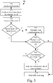
- Fig. 3 illustrates an example method 300 according to some embodiments.
- the method 300 may be for evaluating data traffic in a communication network.
- the method 300 may be carried out by a user plane (UP) node and a control plane (CP) node.
- UP node and CP node are illustrative of the entities that host the control plane and the user plane.
- CP node may e.g. be a base station, a remote server or a computer.
- the UP node may e.g. be a UE, a mobile device, a computer or any other type of suitable communication device.
- the method 300 may e.g. be carried out in a network architecture such as that described in conjunction with Fig. 1 (or other types of network architectures such as 4G), and may concerns detection rules such as the PDRs described in conjunction with Figs. 2a-2b .
- the method starts in step 310 with establishing a protocol session between a control plane, CP, node and a user plane, UP, node.
- the protocol session may e.g. be a Packet Forwarding Control Protocol (PFCP) session.
- PFCP Packet Forwarding Control Protocol
- the CP node configures a first detection rule to be used for event notification, and at least one next detection rule to be used for traffic detection.
- the first detection rule comprises an indicator indicating the highest precedence, and identifies a first instruction rule indicating an event to be notified and also identifies a continuation flag indicating evaluation of at least one next detection rule.
- the at least one next detection rule comprises an indicator indicating a lower precedence than the one in the first detection rule and identifies a next instruction rule to be applied to a matched traffic.
- the CP node transmits the first detection rule and the at least one next detection rule towards the UP node.
- step 312 the UP node receives the first detection rule and the at least one next detection rule.
- step 313 the UP node determines whether a received packet matches the first detection rule.
- step 315 the UP node determines based on the continuation flag, whether the received packet matches any detection rule amongst the at least one next detection rule from higher to lower precedence.
- step 313 When it is determined in step 313 that the received packet matches the first detection rule (Y-path out of 313), the method continues in step 314 where the UP node transmits towards the CP node a notification of the event indicated in the first instruction rule.
- the UP node determines based on the continuation flag, whetherthe received packet matches any detection rule amongst the at least one next detection rule from higher to lower precedence.
- the flag enables for sequential evaluation of the detection rules (e.g. the PDRs), and several detection rules may be matched for event evaluation prior to performing packet detection since the flag indicates that not all rules comprised in the detection rule (such as the FAR) should be carried out.
- the detection rules e.g. the PDRs
- several detection rules may be matched for event evaluation prior to performing packet detection since the flag indicates that not all rules comprised in the detection rule (such as the FAR) should be carried out.
- step 318 If/when it is determined that the received packet does not match the next detection rule (N-path out of 315), the method continues in step 318 by stopping packet matching for the received packet.
- the method 300 may continue in step 316. E.g. if in step 315 the UP node determines that the received packet matches any detection rule amongst the at least one next detection rule (Y-path out of 315), the method continues in step 316 with determining whether the matched next detection rule identifies the continuation flag. If/when the continuation flag is identified (Y-path out of 316) the method loops back to step 314 where the UP node transmits towards the CP node, a notification of the event indicated in the instruction rule of the matched next detection rule and further in step 315 with determining, at the UP node, whether the received packet matches any detection rule amongst other next detection rules from higher to lower precedence.
- the method will loop between steps 314-316 until the packet is matched against a detection rule that does not comprise (i.e. is not configured with) a flag.
- step 317 the UP node applies the next instruction rule of the matched next detection rule to the matched packet, and stops in step 318 the packet matching for the received packet.
- Fig. 4 illustrates a combined flowchart and signaling diagram between a SMF 410 and UPF 420.
- the SMF may e.g. be the SMF or CP node as described in conjunction with any of the previous figures.
- the UPF may be the UPF or UP node as described in conjunction with any of the previous figures.
- Method/signaling diagram as described in conjunction with Fig. 4 may be the method as described in conjunction with Fig. 3 .
- the SMF may establish a protocol session, e.g. by transmitting 401 a PFCP session establishment request to the UPF (compare with step 310 of the method 300).
- the establishment request may comprise a session ID and one or more detection rules (such as PDRs) being configured with a precedence, a flag and instruction rules (compare with step 311 of the method 300).
- the UPF may respond 402 to the SMF with an acknowledgement of establishing the protocol session.
- the UPF may then start matching in step 403 traffic (i.e. data packets) for event detection to the received and configured detection rules (compare with step 313 of method 300). If the packet matches, the event is notified (e.g. using the URR of the detection rule that matched) 404 to the SMF (compare with step 314 of the method 300) which then may take appropriate measures based on the type of detected event.
- the UPF evaluates the following detection rule, which may be the next in line based on the precedence configured to the PDR (compare with step 315 of the method 300).
- the precedence is configured by the SMF, as noted above, and may be sequential in an increasing or decreasing order. Hence a highest precedence (as described in conjunction with any of the previous figures) may have a lowest or highest number, such as 0-N, where N is an integer.
- the precedence may of course be represented by other symbols or being in different formats without deviating from the scope of the embodiments herein, what is of importance is that the precedence indicates that the detection rules that are configured with flags should be matched against first and prior to the detection rules that are not configured with flags.
- the UPF may determine that a following detection rule does not comprise (i.e. is not configured with) a flag (compare with step 316 of method 300). The UPF may then also in step 406 execute the rules (FAR, QER etc) associated with the detection rule that matched and does not comprise a flag (compare with step 317 in the method 300). Then the UPF signals to the SMF 407 the URR reporting of the executed instructions and in step 408 traffic matching is stopped (compare with step 317-318 of method 300).
- the rules FAR, QER etc
- Fig. 5 illustrates an example method 500 for evaluating data traffic in a communication network.
- the method 500 may be carried out at a control plane, CP, node.
- the CP node may in some embodiments be the CP node or SMF as described in conjunction with any of the previous figures.
- the method 500 may in some embodiments, be part of or be combined with the methods 300 and 400 as described in conjunction with the previous figures.
- the method 500 starts in step 510 with establishing a protocol session with a user plane, UP, node.
- the protocol session may e.g. be a PCFP session (compare with steps 310 and 401 of the method 300 and 400).
- the UP node may in some embodiments be the UP node or UPF as described in conjunction with any of the previous figures.
- the method 500 may in some embodiments, be part of or be combined with the methods 300 and 400 as described in conjunction with the previous figures.
- the UP node configures a first detection rule to be used for event notification, and at least one next detection rule to be used for traffic detection (compare with steps 311 and 401 of the methods 300 and 400).
- the first detection rule comprises an indicator indicating the highest precedence (sub-step 523), and identifies a first instruction rule (sub-step 521) indicating an event to be notified and also identifies a continuation flag (sub-step 522) indicating evaluation of at least one next detection rule, and wherein the at least one next detection rule comprises an indicator indicating a lower precedence (sub-step 523) than the one in the first detection rule and identifies a next instruction rule (sub-step 521) to be applied to a matched traffic.
- step 530 After configuring the instruction rules, the method continues in step 530 with transmitting, towards the UP node, the first detection rule and the at least one next detection rule (compare with steps 311 and 401 of methods 300 and 400).
- the CP node receives, from the UP node, a notification of the event indicated in the first instruction rule (compare with steps 314 and 404 of the methods 300 and 400). Based on the received event notification (i.e. the notification of the event), the CP node may take appropriate actions such as remotely block certain apps, increase QoS for a user, or identify tethering.
- the method 500 may further comprise receiving, from the UP node, a notification of an event indicated in a next instruction rule of the at least one next detection rule in the step 540 (compare with steps 317 and 407 of the method 300 and 400).
- Fig. 6 illustrates an example method 600 according to some embodiments.
- the method 600 may be for evaluating data traffic in a communication network.
- the method may be carried out at a user plane, UP, node.
- the UP node may in some embodiments be the UP node or UPF as described in conjunction with any of the previous figures.
- the method 600 starts in step 610 with establishing a protocol session with a control plane, CP, node (compare with steps 310, 401-402 and 510 of methods 300-500).
- the CP node may in some embodiments be the CP node or SMF as described in conjunction with any of the previous figures.
- the method 600 continues in step 611 with receiving, from the CP node, a first detection rule to be used for event notification, and at least one next detection rule to be used for traffic detection (compare with steps 312, 401 and 530 of the methods 300-500).
- the first detection rule comprises an indicator indicating the highest precedence, and identifies a first instruction rule indicating an event to be notified and also identifies a continuation flag indicating evaluation of at least one next detection rule
- the at least one next detection rule comprises an indicator indicating a lower precedence than the one in the first detection rule and identifies a next instruction rule to be applied to a matched traffic (compare with steps 520-523 of method 500).
- step 612 the method 600 comprises determining that a received packet matches the first detection rule (compare with step 313 and 403 of methods 300-400).
- the method continues in step 614, the UP node determines based on the continuation flag, whether the received packet matches any detection rule amongst the at least one next detection rule from higher to lower precedence (compare to steps 315 and 403 of method 300-400).
- step 612 When it is determined in step 612 that the received packet matches the first detection rule (Y-path out of 612, compare with steps 313 and 403 of methods 300-400), the method continues in step 613 where the UP node transmits towards the CP node a notification of the event indicated in the first instruction rule (compare with steps 314, 404 and 540 of methods 300-500).
- the UP node determines based on the continuation flag, whether the received packet matches any detection rule amongst the at least one next detection rule from higher to lower precedence (compare to steps 315 and 403 of method 300-400).
- the flag enables for sequential evaluation of the detection rules (e.g. the PDRs), and several detection rules may be matched for event evaluation prior to performing packet detection since the flag indicates that not all rules comprised in the detection rule (such as the FAR) should be carried out.
- the detection rules e.g. the PDRs
- several detection rules may be matched for event evaluation prior to performing packet detection since the flag indicates that not all rules comprised in the detection rule (such as the FAR) should be carried out.
- step 617 the UP node stops the packet matching for the received packet (compare with steps, 318 and, 408 of methods 300-400).
- the method 600 may further continue in step 615. E.g. if in step 614 the UP node determines that the received packet matches any detection rule amongst the at least one next detection rule (Y-path out of 614), the method continues in step 615 (compare with steps 316 and 405 of methods 300-400) with determining whether the matched next detection rule identifies the continuation flag.
- step 613 the UP node transmits towards the CP node, a notification of the event indicated in the instruction rule of the matched next detection rule and further in step 614 with determining, at the UP node, whether the received packet matches any detection rule amongst other next detection rules from higher to lower precedence.
- the method will loop between steps 613-615 until the packet is matched against a detection rule that does not comprise (i.e. is not configured with) a flag.
- step 616 the UP node applies the next instruction rule of the matched next detection rule to the matched packet, and stops in step 617 the packet matching for the received packet (compare with steps 317, 318 and 407, 408 of methods 300-400).
- any detection rule amongst the first detection rule and the at least one next detection rule, is a Packet Detection Rule, PDR, that comprises a packet filter versus which packets are matched, and identifies one or more associated instruction rules.
- Packet Detection Rule is a common term for 5G architecture, however the embodiments herein are not limited to 5G-networks and are applicable on other detection rules. However, the terms may be used interchangeably in this disclosure.
- the one or more associated instruction rules comprises at least one of:
- the continuation flag is included in one of: the PDR, the FAR, the QER, the BAR and the URR.
- the instruction rules URR, QER, BAR and FAR will all be evaluated and executed. Executing the FAR leads to that packet detection is performed and traffic matching is stopped. Hence if the FAR were to be executed in each detection rule, it would not be possible to perform event evaluation for multiple events.
- the flag can be set in either of the instruction rules and will indicate to the UP node that it should not execute all of the instruction rules comprised in the detection rule (such as the FAR) but should instead utilize the URR to report events to the CP node.
- the CP node may e.g. configure certain detection rules for event notification, for example, if a start of tethering is to be detected, the CP node will configure a detection rule for event notification which will have tethering matching conditions which will be detected by the UP node as it evaluates the URR of the detection rule. If the flag is set, then the UP node will continue evaluation for events in a subsequent detection rule which may be configured for a different event evaluation.
- the first instruction rule indicating the event to be notified is the URR.
- the event to be notified is any one of: tethering detection, video traffic start, and a specific application launch.
- the CP node implements a Session Management Function, SMF
- the UP node implements User Plane Function, UPF
- the protocol session is a Packet Forwarding Control Protocol, PFCP, session.
- Fig. 7 illustrates an arrangement 700 of a control plane, CP, node 710 for evaluating data traffic in a communication network.
- the CP node may e.g. be the CP node or SMF as described in conjunction with any of the preceding figures and may carry out any of the methods 300-500 as previously described.
- the CP node is configured to establish a protocol session with a user plane, UP, node and configure a first detection rule to be used for event notification, and at least one next detection rule to be used for traffic detection.
- the first detection rule comprises an indicator indicating the highest precedence, and identifies a first instruction rule indicating an event to be notified and also identifies a continuation flag indicating evaluation of at least one next detection rule.
- the at least one next detection rule comprises an indicator indicating a lower precedence than the one in the first detection rule and identifies a next instruction rule to be applied to a matched traffic.
- the CP node 710 is also configured to transmit, towards the UP node, the first detection rule and the at least one next detection rule and receive, from the UP node, a notification of the event indicated in the first instruction rule.
- the CP node 710 is further configured to receive, from the UP node, a notification of an event indicated in a next instruction rule of the at least one next detection rule.
- the CP node 710 may comprise controlling circuitry (CNTR; e.g. a controller) 720 configured to cause establishment of a protocol session with a user plane, UP, node and cause configuration of a first detection rule to be used for event notification, and at least one next detection rule to be used for traffic detection.
- the controlling circuitry 720 may comprise or be otherwise associated with a configurer (CONF; e.g. configuration circuitry or a configuration module) 722 for configuring the first and at least one next detection rule.
- CONF configurer
- the controlling circuitry may further comprise, or be otherwise associated with, a session establisher (SESS; e.g., establishing circuitry or an establishing module) 721 for establishing sessions with the UP node.
- SESS session establisher
- the CP node 710 may further comprise an antenna arrangement (such as a transceiver, transmitter, or receiver) (RX/TX) 711 which may be caused by the controlling circuitry to transmit, towards the UP node, the first detection rule and the at least one next detection rule and receive, from the UP node, a notification of the event indicated in the first instruction rule.
- RX/TX antenna arrangement
- the CP node 710 is configured to carry out a method according to any one of the previously described methods 300-500.
- Fig. 8 illustrates an arrangement 800 of a user plane, UP, node 810 for evaluating data traffic in a communication network.
- the UP node 810 may be UP node or UPF as described in conjunction with any of the previous figures.
- the UP node 810 may be configured to carry out any of the methods 300, 400 and 600 as described in conjunction with the Figs. 3 , 4 and 6 .
- the UP node 810 is configured to establish a protocol session with a control plane, CP, node.
- the CP node may e.g. be the CP node or SMF as described in conjunction with any of the previous figures.
- the UP node 810 may be configured to receive, from the CP node, a first detection rule to be used for event notification, and at least one next detection rule to be used for traffic detection.
- the first detection rule comprises an indicator indicating the highest precedence, and identifies a first instruction rule indicating an event to be notified and also identifies a continuation flag indicating evaluation of at least one next detection rule.
- the at least one next detection rule comprises an indicator indicating a lower precedence than the one in the first detection rule and identifies a next instruction rule to be applied to a matched traffic.
- the UP node may be configured to determine that a received packet matches the first detection rule and to transmit, towards the CP node, a notification of the event indicated in the first instruction rule.
- the UP node may be configured to determine, based on the continuation flag, whether the received packet matches any detection rule amongst the at least one next detection rule from higher to lower precedence.
- the arrangement 800 of the UP node 810 may further comprise a controlling circuitry (CNTR; e.g., a controller) 820 configured to cause establishment of a protocol session with a control plane, CP, node.
- the controlling circuitry may be configured to cause the UP node to receive, from the CP node, a first detection rule to be used for event notification, and at least one next detection rule to be used for traffic detection.
- the first detection rule comprises an indicator indicating the highest precedence, and identifies a first instruction rule indicating an event to be notified and also identifies a continuation flag indicating evaluation of at least one next detection rule.
- the at least one next detection rule comprises an indicator indicating a lower precedence than the one in the first detection rule and identifies a next instruction rule to be applied to a matched traffic.
- the controlling circuitry 820 may be configured to cause determination of that a received packet matches the first detection rule and to cause transmission, towards the CP node, of a notification of the event indicated in the first instruction rule.
- controlling circuitry 820 may be configured to determine, based on the continuation flag, whether the received packet matches any detection rule amongst the at least one next detection rule from higher to lower precedence.
- the controlling circuitry 820 may comprise, or be otherwise associated with, a session establisher (SESS; e.g., establishing circuitry or an establishing module) 821 and a determiner (DET; e.g., determining circuitry or a determining module).
- SESS session establisher
- DET determiner
- the UP node arrangement may further comprise a antenna arrangement such as a transceiver, transmitter, and/or receiver (RX/TX) 811.
- the controlling circuitry may be configured to cause the session establisher 821 to establish a protocol session, and cause the determiner 822 to determine whether a received packet matches the first detection rule and determine, based on the continuation flag, whether the received packet matches any detection rule amongst the at least one next detection rule from higher to lower precedence.
- the controlling circuitry may be configured to cause the antenna arrangement to transmit or receive notifications and configured detection rules to/from the CP node.
- the UP node upon determining that the received packet matches any detection rule amongst the at least one next detection rule, is further configured to determine whether the matched next detection rule identifies the continuation flag.
- the UP node is configured to (or the controlling circuitry by e.g. causing the antenna arrangement to) transmit, towards the CP node, a notification of the event indicated in the instruction rule of the matched next detection rule and determine whether the received packet matches any detection rule amongst other next detection rules from higher to lower precedence.
- the UP node is configured to apply (or the controlling circuitry is configured to cause application of) the instruction rule of the matched next detection rule to the matched packet, and stop the packet matching for the received packet.
- the UP node 810 is configured to carry out any of the methods 300, 400 and 600 as described in conjunction with the Figs. 3 , 4 and 6 .
- Fig. 9 illustrates a computer program product comprising a non-transitory computer readable medium 900.
- the non-transitory computer readable medium 900 has stored there on a computer program comprising program instructions.
- the computer program is configured to be loadable into a data-processing unit 910, comprising a processor 920 and a memory 930 associated with or integral to the data-processing unit.
- the computer program When loaded into the data-processing unit 910, the computer program is configured to be stored in the memory 930, wherein the computer program, when loaded into and run by the processor 920 is configured to cause the processor to execute method steps according to any of the methods described in conjunction with the Figs 3-6 .
- DSP digital signal processors
- CPU central processing units
- FPGA field-programmable gate arrays
- ASIC application-specific integrated circuits
- Embodiments may appear within an electronic apparatus (such as a wireless communication device) comprising circuitry/logic or performing methods according to any of the embodiments.
- the electronic apparatus may, for example, be a portable or handheld mobile radio communication equipment, a mobile radio terminal, a mobile telephone, a base station, a base station controller, a pager, a communicator, an electronic organizer, a smartphone, a computer, a notebook, a USB-stick, a plug-in card, an embedded drive, or a mobile gaming device.
- a computer program product comprises a computer readable medium such as, for example, a diskette or a CD-ROM.
- the computer readable medium may have stored thereon a computer program comprising program instructions.
- the computer program may be loadable into a data-processing unit, which may, for example, be comprised in a mobile terminal. When loaded into the data-processing unit, the computer program may be stored in a memory associated with or integral to the data-processing unit.
- Figure 10 illustrates a telecommunication network connected via an intermediate network to a host computer in accordance with some embodiments.
- a communication system includes telecommunication network QQ410, such as a 3GPP-type cellular network, which comprises access network QQ411, such as a radio access network, and core network QQ414.
- Access network QQ411 comprises a plurality of base stations QQ412a, QQ412b, QQ412c, such as NBs, eNBs, gNBs or other types of wireless access points, each defining a corresponding coverage area QQ413a, QQ413b, QQ413c.
- Each base station QQ412a, QQ412b, QQ412c is connectable to core network QQ414 over a wired or wireless connection QQ415.
- a first UE QQ491 located in coverage area QQ413c is configured to wirelessly connect to, or be paged by, the corresponding base station QQ412c.
- a second UE QQ492 in coverage area QQ413a is wirelessly connectable to the corresponding base station QQ412a. While a plurality of UEs QQ491, QQ492 are illustrated in this example, the disclosed embodiments are equally applicable to a situation where a sole UE is in the coverage area or where a sole UE is connecting to the corresponding base station QQ412.
- Telecommunication network QQ410 is itself connected to host computer QQ430, which may be embodied in the hardware and/or software of a standalone server, a cloud-implemented server, a distributed server or as processing resources in a server farm.
- Host computer QQ430 may be under the ownership or control of a service provider, or may be operated by the service provider or on behalf of the service provider.
- Connections QQ421 and QQ422 between telecommunication network QQ410 and host computer QQ430 may extend directly from core network QQ414 to host computer QQ430 or may go via an optional intermediate network QQ420.
- Intermediate network QQ420 may be one of, or a combination of more than one of, a public, private or hosted network; intermediate network QQ420, if any, may be a backbone network or the Internet; in particular, intermediate network QQ420 may comprise two or more sub-networks (not shown).
- the communication system of Figure 10 as a whole enables connectivity between the connected UEs QQ491, QQ492 and host computer QQ430.
- the connectivity may be described as an over-the-top (OTT) connection QQ450.
- Host computer QQ430 and the connected UEs QQ491, QQ492 are configured to communicate data and/or signaling via OTT connection QQ450, using access network QQ411, core network QQ414, any intermediate network QQ420 and possible further infrastructure (not shown) as intermediaries.
- OTT connection QQ450 may be transparent in the sense that the participating communication devices through which OTT connection QQ450 passes are unaware of routing of uplink and downlink communications.
- base station QQ412 may not or need not be informed about the past routing of an incoming downlink communication with data originating from host computer QQ430 to be forwarded (e.g., handed over) to a connected UE QQ491.
- base station QQ412 need not be aware of the future routing of an outgoing uplink communication originating from the UE QQ491 towards the host computer QQ430.
- Figure 11 illustrates a host computer communicating via a base station with a user equipment over a partially wireless connection in accordance with some embodiments.
- host computer QQ510 comprises hardware QQ515 including communication interface QQ516 configured to set up and maintain a wired or wireless connection with an interface of a different communication device of communication system QQ500.
- Host computer QQ510 further comprises processing circuitry QQ518, which may have storage and/or processing capabilities.
- processing circuitry QQ518 may comprise one or more programmable processors, application-specific integrated circuits, field programmable gate arrays or combinations of these (not shown) adapted to execute instructions.
- Host computer QQ510 further comprises software QQ511, which is stored in or accessible by host computer QQ510 and executable by processing circuitry QQ518.
- Software QQ511 includes host application QQ512.
- Host application QQ512 may be operable to provide a service to a remote user, such as UE QQ530 connecting via OTT connection QQ550 terminating at UE QQ530 and host computer QQ510. In providing the service to the remote user, host application QQ512 may provide user data which is transmitted using OTT connection QQ550.
- Communication system QQ500 further includes base station QQ520 provided in a telecommunication system and comprising hardware QQ525 enabling it to communicate with host computer QQ510 and with UE QQ530.
- Hardware QQ525 may include communication interface QQ526 for setting up and maintaining a wired or wireless connection with an interface of a different communication device of communication system QQ500, as well as radio interface QQ527 for setting up and maintaining at least wireless connection QQ570 with UE QQ530 located in a coverage area (not shown in Figure 11 ) served by base station QQ520.
- Communication interface QQ526 may be configured to facilitate connection QQ560 to host computer QQ510.
- Connection QQ560 may be direct or it may pass through a core network (not shown in Figure 11 ) of the telecommunication system and/or through one or more intermediate networks outside the telecommunication system.
- hardware QQ525 of base station QQ520 further includes processing circuitry QQ528, which may comprise one or more programmable processors, application-specific integrated circuits, field programmable gate arrays or combinations of these (not shown) adapted to execute instructions.
- Base station QQ520 further has software QQ521 stored internally or accessible via an external connection.
- Communication system QQ500 further includes UE QQ530 already referred to.
- Its hardware QQ535 may include radio interface QQ537 configured to set up and maintain wireless connection QQ570 with a base station serving a coverage area in which UE QQ530 is currently located.
- Hardware QQ535 of UE QQ530 further includes processing circuitry QQ538, which may comprise one or more programmable processors, application-specific integrated circuits, field programmable gate arrays or combinations of these (not shown) adapted to execute instructions.
- UE QQ530 further comprises software QQ531, which is stored in or accessible by UE QQ530 and executable by processing circuitry QQ538.
- Software QQ531 includes client application QQ532.
- Client application QQ532 may be operable to provide a service to a human or non-human user via UE QQ530, with the support of host computer QQ510.
- an executing host application QQ512 may communicate with the executing client application QQ532 via OTT connection QQ550 terminating at UE QQ530 and host computer QQ510.
- client application QQ532 may receive request data from host application QQ512 and provide user data in response to the request data.
- OTT connection QQ550 may transfer both the request data and the user data.
- Client application QQ532 may interact with the user to generate the user data that it provides.
- host computer QQ510, base station QQ520 and UE QQ530 illustrated in Figure 11 may be similar or identical to host computer QQ430, one of base stations QQ412a, QQ412b, QQ412c and one of UEs QQ491, QQ492 of Figure 10 , respectively.
- the inner workings of these entities may be as shown in Figure 11 and independently, the surrounding network topology may be that of Figure 10 .
- OTT connection QQ550 has been drawn abstractly to illustrate the communication between host computer QQ510 and UE QQ530 via base station QQ520, without explicit reference to any intermediary devices and the precise routing of messages via these devices.
- Network infrastructure may determine the routing, which it may be configured to hide from UE QQ530 or from the service provider operating host computer QQ510, or both. While OTT connection QQ550 is active, the network infrastructure may further take decisions by which it dynamically changes the routing (e.g., on the basis of load balancing consideration or reconfiguration of the network).
- Wireless connection QQ570 between UE QQ530 and base station QQ520 is in accordance with the teachings of the embodiments described throughout this disclosure.
- One or more of the various embodiments improve the performance of OTT services provided to UE QQ530 using OTT connection QQ550, in which wireless connection QQ570 forms the last segment. More precisely, the teachings of these embodiments may improve security as explained above.
- a measurement procedure may be provided for the purpose of monitoring data rate, latency and other factors on which the one or more embodiments improve.
- the measurement procedure and/or the network functionality for reconfiguring OTT connection QQ550 may be implemented in software QQ511 and hardware QQ515 of host computer QQ510 or in software QQ531 and hardware QQ535 of UE QQ530, or both.
- sensors may be deployed in or in association with communication devices through which OTT connection QQ550 passes; the sensors may participate in the measurement procedure by supplying values of the monitored quantities exemplified above, or supplying values of other physical quantities from which software QQ511, QQ531 may compute or estimate the monitored quantities.
- the reconfiguring of OTT connection QQ550 may include message format, retransmission settings, preferred routing etc.; the reconfiguring need not affect base station QQ520, and it may be unknown or imperceptible to base station QQ520. Such procedures and functionalities may be known and practiced in the art.
- measurements may involve proprietary UE signaling facilitating host computer QQ510's measurements of throughput, propagation times, latency and the like. The measurements may be implemented in that software QQ511 and QQ531 causes messages to be transmitted, in particular empty or 'dummy' messages, using OTT connection QQ550 while it monitors propagation times, errors etc.
- Figure 12 illustrates methods implemented in a communication system including a host computer, a base station and a user equipment in accordance with some embodiments
- FIG 12 is a flowchart illustrating a method implemented in a communication system, in accordance with one embodiment.
- the communication system includes a host computer, a base station and a UE which may be those described with reference to Figures 10 and 11 .
- the host computer provides user data.
- sub-step QQ611 (which may be optional) of step QQ610, the host computer provides the user data by executing a host application.
- step QQ620 the host computer initiates a transmission carrying the user data to the UE.
- step QQ630 the base station transmits to the UE the user data which was carried in the transmission that the host computer initiated, in accordance with the teachings of the embodiments described throughout this disclosure.
- step QQ640 the UE executes a client application associated with the host application executed by the host computer.
- Figure 13 illustrates methods implemented in a communication system including a host computer, a base station and a user equipment in accordance with some embodiments
- FIG. 13 is a flowchart illustrating a method implemented in a communication system, in accordance with one embodiment.
- the communication system includes a host computer, a base station and a UE which may be those described with reference to Figures 10 and 11 .
- the host computer provides user data.
- the host computer provides the user data by executing a host application.
- the host computer initiates a transmission carrying the user data to the UE.
- the transmission may pass via the base station, in accordance with the teachings of the embodiments described throughout this disclosure.
- step QQ730 (which may be optional), the UE receives the user data carried in the transmission.
- Figure 14 illustrates methods implemented in a communication system including a host computer, a base station and a user equipment in accordance with some embodiments
- FIG 14 is a flowchart illustrating a method implemented in a communication system, in accordance with one embodiment.
- the communication system includes a host computer, a base station and a UE which may be those described with reference to Figures 10 and 11 .
- the UE receives input data provided by the host computer.
- the UE provides user data.
- sub-step QQ821 (which may be optional) of step QQ820, the UE provides the user data by executing a client application.
- sub-step QQ811 (which may be optional) of step QQ810, the UE executes a client application which provides the user data in reaction to the received input data provided by the host computer. In providing the user data, the executed client application may further consider user input received from the user. Regardless of the specific manner in which the user data was provided, the UE initiates, in sub-step QQ830 (which may be optional), transmission of the user data to the host computer.
- step QQ840 of the method the host computer receives the user data transmitted from the UE, in accordance with the teachings of the embodiments described throughout this disclosure.
- Figure 15 illustrates methods implemented in a communication system including a host computer, a base station and a user equipment in accordance with some embodiments
- FIG 15 is a flowchart illustrating a method implemented in a communication system, in accordance with one embodiment.
- the communication system includes a host computer, a base station and a UE which may be those described with reference to Figures 10 and 11 .
- the base station receives user data from the UE.
- the base station initiates transmission of the received user data to the host computer.
- the host computer receives the user data carried in the transmission initiated by the base station.
Landscapes
- Engineering & Computer Science (AREA)
- Computer Networks & Wireless Communication (AREA)
- Signal Processing (AREA)
- Business, Economics & Management (AREA)
- General Business, Economics & Management (AREA)
- Computer Hardware Design (AREA)
- Computer Security & Cryptography (AREA)
- Computing Systems (AREA)
- General Engineering & Computer Science (AREA)
- Data Exchanges In Wide-Area Networks (AREA)
- Mobile Radio Communication Systems (AREA)
Claims (15)
- Procédé (500) d'évaluation de trafic de données dans un réseau de communication, le procédé étant réalisé au niveau d'un nœud de plan de commande, CP, et comprenant :l'établissement (510) d'une session de protocole avec un nœud de plan d'utilisateur, UP ;la configuration (520) d'une première règle de détection à utiliser pour une notification d'événement, et d'au moins une règle de détection suivante à utiliser pour une détection de trafic, dans lequel la première règle de détection comprend un indicateur indiquant la plus haute priorité, et identifie une première règle d'instruction indiquant un événement à notifier et un drapeau de continuation indiquant une évaluation d'au moins une règle de détection suivante, et dans lequel l'au moins une règle de détection suivante comprend un indicateur indiquant une priorité inférieure à celle de la première règle de détection et identifie une règle d'instruction suivante à appliquer à un trafic mis en correspondance ;la transmission (530), vers le nœud UP, de la première règle de détection et de l'au moins une règle de détection suivante ; etla réception (540), depuis le nœud UP, d'une notification de l'événement indiqué dans la première règle d'instruction.
- Procédé selon la revendication 1, dans lequel le procédé comprend :la réception (540), depuis le nœud UP, d'une notification d'un événement indiqué dans une règle d'instruction suivante de l'au moins une règle de détection suivante.
- Procédé (600) d'évaluation de trafic de données dans un réseau de communication, le procédé étant réalisé au niveau d'un nœud de plan d'utilisateur, UP, et comprenant :l'établissement (610) d'une session de protocole avec un nœud de plan de commande, CP ;la réception (611), depuis le nœud CP, d'une première règle de détection à utiliser pour une notification d'événement, et d'au moins une règle de détection suivante à utiliser pour une détection de trafic, dans lequel la première règle de détection comprend un indicateur indiquant la plus haute priorité, et identifie une première règle d'instruction indiquant un événement à notifier et un drapeau de continuation indiquant une évaluation d'au moins une règle de détection suivante, et dans lequel l'au moins une règle de détection suivante comprend un indicateur indiquant une priorité inférieure à celle de la première règle de détection et identifie une règle d'instruction suivante à appliquer à un trafic mis en correspondance ;la détermination (612) qu'un paquet reçu correspond à la première règle de détection ;la transmission (613), vers le nœud CP, d'une notification de l'événement indiqué dans la première règle d'instruction ; etla détermination (614), sur la base du drapeau de continuation, si le paquet reçu correspond ou non à une règle de détection quelconque parmi l'au moins une règle de détection suivante d'une plus haute priorité à une plus basse priorité.
- Procédé selon la revendication 3, dans lequel, à la détermination (614) que le paquet reçu correspond à une règle de détection quelconque parmi l'au moins une règle de détection suivante, le procédé comprend :la détermination (615) si la règle de détection suivante mise en correspondance identifie ou non le drapeau de continuation ;si le drapeau de continuation est identifié, la transmission (613), vers le nœud CP, d'une notification de l'événement indiqué dans la règle d'instruction de la règle de détection suivante mise en correspondance et la détermination (614) si le paquet reçu correspond ou non à une règle de détection quelconque parmi d'autres règles de détection suivantes d'une plus haute priorité à une plus basse priorité ;si le drapeau de continuation n'est pas identifié, l'application (616) de la règle d'instruction de la règle de détection suivante mise en correspondance au paquet mis en correspondance, et l'arrêt (617) de la mise en correspondance de paquet pour le paquet reçu.
- Procédé selon l'une quelconque des revendications 1 à 4, dans lequel une règle de détection quelconque, parmi la première règle de détection et l'au moins une règle de détection suivante, est une règle de détection de paquets, PDR, qui comprend un filtre de paquets avec lequel des paquets sont mis en correspondance, et identifie une ou plusieurs règles d'instruction associées.
- Procédé selon la revendication 5, dans lequel les une ou plusieurs règles d'instruction associées comprennent au moins l'une parmi :une règle d'action de transfert, FAR, qui contient des instructions relatives au traitement des paquets ;une règle de respect de qualité de service, QER, qui contient des instructions relatives au respect de QoS du trafic ;une règle de rapport d'utilisateur, URR, qui contient des instructions relatives à une mesure et un rapport de trafic ; etune règle d'action de mise en mémoire tampon, BAR, qui contient des règles de mise en mémoire tampon à appliquer aux paquets correspondants.
- Procédé selon la revendication 6, dans lequel le drapeau de continuation est inclus dans l'une parmi : la PDR, la FAR, la QER, la BAR et l'URR.
- Procédé selon la revendication 6 ou 7, dans lequel la première règle d'instruction indiquant l'événement à notifier est l'URR.
- Procédé selon l'une quelconque des revendications 1 à 8, dans lequel l'événement à notifier est l'un quelconque parmi : une détection de rattachement, un début de trafic vidéo, et un lancement d'application spécifique.
- Procédé selon l'une quelconque des revendications 1 à 9, dans lequel le nœud CP met en œuvre une fonction de gestion de session, SMF, le nœud UP met en œuvre une fonction de plan d'utilisateur, UPF, et la session de protocole est une session de protocole de commande de transfert de paquets, PFCP.
- Nœud de plan de commande, CP, (710) pour évaluer un trafic de données dans un réseau de communication, le nœud CP étant configuré pour :établir une session de protocole avec un nœud de plan d'utilisateur, UP ;configurer une première règle de détection à utiliser pour une notification d'événement, et au moins une règle de détection suivante à utiliser pour une détection de trafic, dans lequel la première règle de détection comprend un indicateur indiquant la plus haute priorité, et identifie une première règle d'instruction indiquant un événement à notifier et un drapeau de continuation indiquant une évaluation d'au moins une règle de détection suivante, et dans lequel l'au moins une règle de détection suivante comprend un indicateur indiquant une priorité inférieure à celle de la première règle de détection et identifie une règle d'instruction suivante à appliquer à un trafic mis en correspondance ;transmettre, vers le nœud UP, la première règle de détection et l'au moins une règle de détection suivante ; etrecevoir, depuis le nœud UP, une notification de l'événement indiqué dans la première règle d'instruction.
- Nœud CP selon la revendication 11, dans lequel le nœud CP est configuré pour réaliser un procédé selon la revendication 2 ou l'une quelconque des revendications 5 à 10.
- Nœud de plan d'utilisateur, UP, (810) pour évaluer un trafic de données dans un réseau de communication, le nœud UP étant configuré pour :établir une session de protocole avec un nœud de plan de commande, CP ;recevoir, depuis le nœud CP, une première règle de détection à utiliser pour une notification d'événement, et au moins une règle de détection suivante à utiliser pour une détection de trafic, dans lequel la première règle de détection comprend un indicateur indiquant la plus haute priorité, et identifie une première règle d'instruction indiquant un événement à notifier et un drapeau de continuation indiquant une évaluation d'au moins une règle de détection suivante, et dans lequel l'au moins une règle de détection suivante comprend un indicateur indiquant une priorité inférieure à celle de la première règle de détection et identifie une règle d'instruction suivante à appliquer à un trafic mis en correspondance ;déterminer qu'un paquet reçu correspond à la première règle de détection ;transmettre, vers le nœud CP, une notification de l'événement indiqué dans la première règle d'instruction ; etdéterminer, sur la base du drapeau de continuation, si le paquet reçu correspond ou non à une règle de détection quelconque parmi l'au moins une règle de détection suivante d'une plus haute priorité à une plus basse priorité.
- Nœud UP selon la revendication 13, dans lequel le nœud UP est configuré pour réaliser un procédé selon la revendication 4 ou l'une quelconque des revendications 5 à 10.
- Produit de programme informatique comprenant un support non transitoire lisible par ordinateur (900), dans lequel le support non transitoire lisible par ordinateur (900) stocke un programme informatique comprenant des instructions de programme, dans lequel le programme informatique est configuré pour pouvoir être chargé dans une unité de traitement de données (910), comprenant un processeur (920) et une mémoire (930) associée ou intégrée à l'unité de traitement de données, dans lequel, lorsqu'il est chargé dans l'unité de traitement de données (910), le programme informatique est configuré pour être stocké dans la mémoire (930), dans lequel le programme informatique, lorsqu'il est chargé dans le processeur (920) et exécuté par celui-ci, est configuré pour amener le processeur à exécuter toutes les étapes d'un procédé selon l'une quelconque des revendications 1 à 10.
Applications Claiming Priority (2)
| Application Number | Priority Date | Filing Date | Title |
|---|---|---|---|
| EP19382558 | 2019-07-01 | ||
| PCT/EP2019/069664 WO2021001050A1 (fr) | 2019-07-01 | 2019-07-22 | Mise en correspondance séquentielle de paquets |
Publications (2)
| Publication Number | Publication Date |
|---|---|
| EP3994859A1 EP3994859A1 (fr) | 2022-05-11 |
| EP3994859B1 true EP3994859B1 (fr) | 2022-12-21 |
Family
ID=67226205
Family Applications (1)
| Application Number | Title | Priority Date | Filing Date |
|---|---|---|---|
| EP19742205.8A Active EP3994859B1 (fr) | 2019-07-01 | 2019-07-22 | Mise en correspondance séquentielle de paquets |
Country Status (3)
| Country | Link |
|---|---|
| US (1) | US11996995B2 (fr) |
| EP (1) | EP3994859B1 (fr) |
| WO (1) | WO2021001050A1 (fr) |
Cited By (1)
| Publication number | Priority date | Publication date | Assignee | Title |
|---|---|---|---|---|
| US20230007485A1 (en) * | 2021-06-30 | 2023-01-05 | At&T Mobility Ii Llc | Systems and methods for network anomalies management |
Families Citing this family (2)
| Publication number | Priority date | Publication date | Assignee | Title |
|---|---|---|---|---|
| KR102304330B1 (ko) * | 2019-10-30 | 2021-09-23 | 에스케이텔레콤 주식회사 | 복수의 UPF 인스턴스들을 포함하는 UPF 노드가 QoS(Quality of Service) 모니터링을 수행하는 방법 및 상기 방법을 수행하는 UPF 노드 |
| CN117667965B (zh) * | 2024-02-01 | 2024-04-30 | 江苏林洋亿纬储能科技有限公司 | 管理电池储能系统大数据的方法和系统及计算设备 |
Family Cites Families (1)
| Publication number | Priority date | Publication date | Assignee | Title |
|---|---|---|---|---|
| US10887944B2 (en) * | 2018-08-20 | 2021-01-05 | Telefonaktiebolaget Lm Ericsson (Publ) | User plane function control of control plane-user plane separation |
-
2019
- 2019-07-22 US US17/622,967 patent/US11996995B2/en active Active
- 2019-07-22 WO PCT/EP2019/069664 patent/WO2021001050A1/fr not_active Ceased
- 2019-07-22 EP EP19742205.8A patent/EP3994859B1/fr active Active
Non-Patent Citations (1)
| Title |
|---|
| "LTE; Interface between the Control Plane and the User Plane nodes (3GPP TS 29.244 version 14.5.0 Release 14)", vol. 3GPP CT, no. V14.5.0, 9 October 2018 (2018-10-09), pages 1 - 171, XP014329999, Retrieved from the Internet <URL:http://www.etsi.org/deliver/etsi_ts/129200_129299/129244/14.05.00_60/ts_129244v140500p.pdf> [retrieved on 20181009] * |
Cited By (1)
| Publication number | Priority date | Publication date | Assignee | Title |
|---|---|---|---|---|
| US20230007485A1 (en) * | 2021-06-30 | 2023-01-05 | At&T Mobility Ii Llc | Systems and methods for network anomalies management |
Also Published As
| Publication number | Publication date |
|---|---|
| US20220272008A1 (en) | 2022-08-25 |
| EP3994859A1 (fr) | 2022-05-11 |
| US11996995B2 (en) | 2024-05-28 |
| WO2021001050A1 (fr) | 2021-01-07 |
Similar Documents
| Publication | Publication Date | Title |
|---|---|---|
| KR101474621B1 (ko) | 네트워크 접속을 갖는 피어 투 피어 직접 링크 통신을 제공하기 위한 방법 및 장치 | |
| US12302161B2 (en) | QoS mapping | |
| JP2022545406A (ja) | マルチtrpおよびマルチパネル伝送を用いるビーム障害検出および回復 | |
| CN118102436A (zh) | 用于处置拒绝时的无线电接入网通知区域(rna)更新配置的方法和设备 | |
| EP3017639B1 (fr) | Allocation adaptative de ressources pour fonctionnement simultané de communications cellulaires et de dispositif à dispositif | |
| WO2019059836A1 (fr) | Procédés et unités dans un nœud de réseau destiné au traitement d'une communication avec un dispositif sans fil | |
| CN113811021B (zh) | 通信方法和装置 | |
| CN110366112A (zh) | 一种定位方法及相关设备 | |
| CN114467286B (zh) | 注册和配置用于选择性路由上行链路数据业务的网络功能 | |
| US11425607B2 (en) | Management of uplink bitrates | |
| EP3994859B1 (fr) | Mise en correspondance séquentielle de paquets | |
| WO2016168829A1 (fr) | Casque d'écoute intelligent et procédé de routage de service en réaction à la proximité d'un dispositif mobile | |
| WO2019216805A1 (fr) | Procédures de réinitialisation de mac | |
| WO2022212699A1 (fr) | Mécanisme d'activation/de désactivation pour un groupe de cellules secondaires (scg) et des cellules secondaires (scells), et changement/ajout conditionnel de cellule secondaire primaire (pscell) | |
| JPWO2014024342A1 (ja) | 通信装置、通信方法、プログラム、及び配信サーバ | |
| EP4500944A1 (fr) | Informations d'assistance de communication sensibles au temps | |
| US9253703B1 (en) | Methods and systems for considering the congestion level of an inter-base-station link during handoff of a mobile station | |
| US12219379B2 (en) | Relaxed inter-frequency measurements | |
| US20250338156A1 (en) | Methods for ue initiated aperiodic l1 measurement report for detected cells based on l3 measurements | |
| WO2020250073A1 (fr) | Accord de priorité à une demande d'ordonnancement | |
| WO2021018420A1 (fr) | Détection de paquets | |
| JP2014116703A (ja) | 通信システム、通信装置および回線選択制御方法 | |
| WO2025168879A1 (fr) | Procédé pour des améliorations d'interface de réseau à fonction d'application pour une sélection de tranche initiée par réseau dans le cas d'un encombrement de tranche de réseau | |
| EP4612894A1 (fr) | Amélioration de découverte et de connexion pc5 pour ai/ml sur pc5 | |
| EP3422670B1 (fr) | Dispositif de communication, procédé de communication et système de communication |
Legal Events
| Date | Code | Title | Description |
|---|---|---|---|
| STAA | Information on the status of an ep patent application or granted ep patent |
Free format text: STATUS: UNKNOWN |
|
| STAA | Information on the status of an ep patent application or granted ep patent |
Free format text: STATUS: THE INTERNATIONAL PUBLICATION HAS BEEN MADE |
|
| PUAI | Public reference made under article 153(3) epc to a published international application that has entered the european phase |
Free format text: ORIGINAL CODE: 0009012 |
|
| STAA | Information on the status of an ep patent application or granted ep patent |
Free format text: STATUS: REQUEST FOR EXAMINATION WAS MADE |
|
| 17P | Request for examination filed |
Effective date: 20220113 |
|
| AK | Designated contracting states |
Kind code of ref document: A1 Designated state(s): AL AT BE BG CH CY CZ DE DK EE ES FI FR GB GR HR HU IE IS IT LI LT LU LV MC MK MT NL NO PL PT RO RS SE SI SK SM TR |
|
| REG | Reference to a national code |
Ref country code: DE Ref legal event code: R079 Ref document number: 602019023429 Country of ref document: DE Free format text: PREVIOUS MAIN CLASS: H04L0029060000 Ipc: H04W0084040000 |
|
| RIC1 | Information provided on ipc code assigned before grant |
Ipc: H04W 84/04 20090101AFI20220728BHEP |
|
| GRAP | Despatch of communication of intention to grant a patent |
Free format text: ORIGINAL CODE: EPIDOSNIGR1 |
|
| STAA | Information on the status of an ep patent application or granted ep patent |
Free format text: STATUS: GRANT OF PATENT IS INTENDED |
|
| DAV | Request for validation of the european patent (deleted) | ||
| DAX | Request for extension of the european patent (deleted) | ||
| INTG | Intention to grant announced |
Effective date: 20220919 |
|
| GRAS | Grant fee paid |
Free format text: ORIGINAL CODE: EPIDOSNIGR3 |
|
| GRAA | (expected) grant |
Free format text: ORIGINAL CODE: 0009210 |
|
| STAA | Information on the status of an ep patent application or granted ep patent |
Free format text: STATUS: THE PATENT HAS BEEN GRANTED |
|
| AK | Designated contracting states |
Kind code of ref document: B1 Designated state(s): AL AT BE BG CH CY CZ DE DK EE ES FI FR GB GR HR HU IE IS IT LI LT LU LV MC MK MT NL NO PL PT RO RS SE SI SK SM TR |
|
| REG | Reference to a national code |
Ref country code: GB Ref legal event code: FG4D |
|
| REG | Reference to a national code |
Ref country code: DE Ref legal event code: R096 Ref document number: 602019023429 Country of ref document: DE |
|
| REG | Reference to a national code |
Ref country code: CH Ref legal event code: EP |
|
| REG | Reference to a national code |
Ref country code: AT Ref legal event code: REF Ref document number: 1539829 Country of ref document: AT Kind code of ref document: T Effective date: 20230115 |
|
| REG | Reference to a national code |
Ref country code: IE Ref legal event code: FG4D |
|
| REG | Reference to a national code |
Ref country code: LT Ref legal event code: MG9D |
|
| REG | Reference to a national code |
Ref country code: NL Ref legal event code: MP Effective date: 20221221 |
|
| PG25 | Lapsed in a contracting state [announced via postgrant information from national office to epo] |
Ref country code: SE Free format text: LAPSE BECAUSE OF FAILURE TO SUBMIT A TRANSLATION OF THE DESCRIPTION OR TO PAY THE FEE WITHIN THE PRESCRIBED TIME-LIMIT Effective date: 20221221 Ref country code: NO Free format text: LAPSE BECAUSE OF FAILURE TO SUBMIT A TRANSLATION OF THE DESCRIPTION OR TO PAY THE FEE WITHIN THE PRESCRIBED TIME-LIMIT Effective date: 20230321 Ref country code: LT Free format text: LAPSE BECAUSE OF FAILURE TO SUBMIT A TRANSLATION OF THE DESCRIPTION OR TO PAY THE FEE WITHIN THE PRESCRIBED TIME-LIMIT Effective date: 20221221 Ref country code: FI Free format text: LAPSE BECAUSE OF FAILURE TO SUBMIT A TRANSLATION OF THE DESCRIPTION OR TO PAY THE FEE WITHIN THE PRESCRIBED TIME-LIMIT Effective date: 20221221 |
|
| REG | Reference to a national code |
Ref country code: AT Ref legal event code: MK05 Ref document number: 1539829 Country of ref document: AT Kind code of ref document: T Effective date: 20221221 |
|
| PG25 | Lapsed in a contracting state [announced via postgrant information from national office to epo] |
Ref country code: RS Free format text: LAPSE BECAUSE OF FAILURE TO SUBMIT A TRANSLATION OF THE DESCRIPTION OR TO PAY THE FEE WITHIN THE PRESCRIBED TIME-LIMIT Effective date: 20221221 Ref country code: LV Free format text: LAPSE BECAUSE OF FAILURE TO SUBMIT A TRANSLATION OF THE DESCRIPTION OR TO PAY THE FEE WITHIN THE PRESCRIBED TIME-LIMIT Effective date: 20221221 Ref country code: HR Free format text: LAPSE BECAUSE OF FAILURE TO SUBMIT A TRANSLATION OF THE DESCRIPTION OR TO PAY THE FEE WITHIN THE PRESCRIBED TIME-LIMIT Effective date: 20221221 Ref country code: GR Free format text: LAPSE BECAUSE OF FAILURE TO SUBMIT A TRANSLATION OF THE DESCRIPTION OR TO PAY THE FEE WITHIN THE PRESCRIBED TIME-LIMIT Effective date: 20230322 |
|
| PG25 | Lapsed in a contracting state [announced via postgrant information from national office to epo] |
Ref country code: NL Free format text: LAPSE BECAUSE OF FAILURE TO SUBMIT A TRANSLATION OF THE DESCRIPTION OR TO PAY THE FEE WITHIN THE PRESCRIBED TIME-LIMIT Effective date: 20221221 |
|
| PG25 | Lapsed in a contracting state [announced via postgrant information from national office to epo] |
Ref country code: SM Free format text: LAPSE BECAUSE OF FAILURE TO SUBMIT A TRANSLATION OF THE DESCRIPTION OR TO PAY THE FEE WITHIN THE PRESCRIBED TIME-LIMIT Effective date: 20221221 Ref country code: RO Free format text: LAPSE BECAUSE OF FAILURE TO SUBMIT A TRANSLATION OF THE DESCRIPTION OR TO PAY THE FEE WITHIN THE PRESCRIBED TIME-LIMIT Effective date: 20221221 Ref country code: PT Free format text: LAPSE BECAUSE OF FAILURE TO SUBMIT A TRANSLATION OF THE DESCRIPTION OR TO PAY THE FEE WITHIN THE PRESCRIBED TIME-LIMIT Effective date: 20230421 Ref country code: ES Free format text: LAPSE BECAUSE OF FAILURE TO SUBMIT A TRANSLATION OF THE DESCRIPTION OR TO PAY THE FEE WITHIN THE PRESCRIBED TIME-LIMIT Effective date: 20221221 Ref country code: EE Free format text: LAPSE BECAUSE OF FAILURE TO SUBMIT A TRANSLATION OF THE DESCRIPTION OR TO PAY THE FEE WITHIN THE PRESCRIBED TIME-LIMIT Effective date: 20221221 Ref country code: CZ Free format text: LAPSE BECAUSE OF FAILURE TO SUBMIT A TRANSLATION OF THE DESCRIPTION OR TO PAY THE FEE WITHIN THE PRESCRIBED TIME-LIMIT Effective date: 20221221 Ref country code: AT Free format text: LAPSE BECAUSE OF FAILURE TO SUBMIT A TRANSLATION OF THE DESCRIPTION OR TO PAY THE FEE WITHIN THE PRESCRIBED TIME-LIMIT Effective date: 20221221 |
|
| PG25 | Lapsed in a contracting state [announced via postgrant information from national office to epo] |
Ref country code: SK Free format text: LAPSE BECAUSE OF FAILURE TO SUBMIT A TRANSLATION OF THE DESCRIPTION OR TO PAY THE FEE WITHIN THE PRESCRIBED TIME-LIMIT Effective date: 20221221 Ref country code: PL Free format text: LAPSE BECAUSE OF FAILURE TO SUBMIT A TRANSLATION OF THE DESCRIPTION OR TO PAY THE FEE WITHIN THE PRESCRIBED TIME-LIMIT Effective date: 20221221 Ref country code: IS Free format text: LAPSE BECAUSE OF FAILURE TO SUBMIT A TRANSLATION OF THE DESCRIPTION OR TO PAY THE FEE WITHIN THE PRESCRIBED TIME-LIMIT Effective date: 20230421 Ref country code: AL Free format text: LAPSE BECAUSE OF FAILURE TO SUBMIT A TRANSLATION OF THE DESCRIPTION OR TO PAY THE FEE WITHIN THE PRESCRIBED TIME-LIMIT Effective date: 20221221 |
|
| REG | Reference to a national code |
Ref country code: DE Ref legal event code: R097 Ref document number: 602019023429 Country of ref document: DE |
|
| PLBE | No opposition filed within time limit |
Free format text: ORIGINAL CODE: 0009261 |
|
| STAA | Information on the status of an ep patent application or granted ep patent |
Free format text: STATUS: NO OPPOSITION FILED WITHIN TIME LIMIT |
|
| PG25 | Lapsed in a contracting state [announced via postgrant information from national office to epo] |
Ref country code: DK Free format text: LAPSE BECAUSE OF FAILURE TO SUBMIT A TRANSLATION OF THE DESCRIPTION OR TO PAY THE FEE WITHIN THE PRESCRIBED TIME-LIMIT Effective date: 20221221 |
|
| 26N | No opposition filed |
Effective date: 20230922 |
|
| PGFP | Annual fee paid to national office [announced via postgrant information from national office to epo] |
Ref country code: DE Payment date: 20230727 Year of fee payment: 5 |
|
| PG25 | Lapsed in a contracting state [announced via postgrant information from national office to epo] |
Ref country code: SI Free format text: LAPSE BECAUSE OF FAILURE TO SUBMIT A TRANSLATION OF THE DESCRIPTION OR TO PAY THE FEE WITHIN THE PRESCRIBED TIME-LIMIT Effective date: 20221221 |
|
| PG25 | Lapsed in a contracting state [announced via postgrant information from national office to epo] |
Ref country code: MC Free format text: LAPSE BECAUSE OF FAILURE TO SUBMIT A TRANSLATION OF THE DESCRIPTION OR TO PAY THE FEE WITHIN THE PRESCRIBED TIME-LIMIT Effective date: 20221221 |
|
| PG25 | Lapsed in a contracting state [announced via postgrant information from national office to epo] |
Ref country code: MC Free format text: LAPSE BECAUSE OF FAILURE TO SUBMIT A TRANSLATION OF THE DESCRIPTION OR TO PAY THE FEE WITHIN THE PRESCRIBED TIME-LIMIT Effective date: 20221221 |
|
| REG | Reference to a national code |
Ref country code: CH Ref legal event code: PL |
|
| REG | Reference to a national code |
Ref country code: BE Ref legal event code: MM Effective date: 20230731 |
|
| PG25 | Lapsed in a contracting state [announced via postgrant information from national office to epo] |
Ref country code: LU Free format text: LAPSE BECAUSE OF NON-PAYMENT OF DUE FEES Effective date: 20230722 |
|
| PG25 | Lapsed in a contracting state [announced via postgrant information from national office to epo] |
Ref country code: LU Free format text: LAPSE BECAUSE OF NON-PAYMENT OF DUE FEES Effective date: 20230722 |
|
| REG | Reference to a national code |
Ref country code: IE Ref legal event code: MM4A |
|
| PG25 | Lapsed in a contracting state [announced via postgrant information from national office to epo] |
Ref country code: CH Free format text: LAPSE BECAUSE OF NON-PAYMENT OF DUE FEES Effective date: 20230731 |
|
| PG25 | Lapsed in a contracting state [announced via postgrant information from national office to epo] |
Ref country code: IT Free format text: LAPSE BECAUSE OF FAILURE TO SUBMIT A TRANSLATION OF THE DESCRIPTION OR TO PAY THE FEE WITHIN THE PRESCRIBED TIME-LIMIT Effective date: 20221221 Ref country code: FR Free format text: LAPSE BECAUSE OF NON-PAYMENT OF DUE FEES Effective date: 20230731 Ref country code: BE Free format text: LAPSE BECAUSE OF NON-PAYMENT OF DUE FEES Effective date: 20230731 |
|
| PG25 | Lapsed in a contracting state [announced via postgrant information from national office to epo] |
Ref country code: IE Free format text: LAPSE BECAUSE OF NON-PAYMENT OF DUE FEES Effective date: 20230722 |
|
| PG25 | Lapsed in a contracting state [announced via postgrant information from national office to epo] |
Ref country code: IE Free format text: LAPSE BECAUSE OF NON-PAYMENT OF DUE FEES Effective date: 20230722 |
|
| PG25 | Lapsed in a contracting state [announced via postgrant information from national office to epo] |
Ref country code: BG Free format text: LAPSE BECAUSE OF FAILURE TO SUBMIT A TRANSLATION OF THE DESCRIPTION OR TO PAY THE FEE WITHIN THE PRESCRIBED TIME-LIMIT Effective date: 20221221 |
|
| PG25 | Lapsed in a contracting state [announced via postgrant information from national office to epo] |
Ref country code: BG Free format text: LAPSE BECAUSE OF FAILURE TO SUBMIT A TRANSLATION OF THE DESCRIPTION OR TO PAY THE FEE WITHIN THE PRESCRIBED TIME-LIMIT Effective date: 20221221 |
|
| REG | Reference to a national code |
Ref country code: DE Ref legal event code: R119 Ref document number: 602019023429 Country of ref document: DE |
|
| PG25 | Lapsed in a contracting state [announced via postgrant information from national office to epo] |
Ref country code: DE Free format text: LAPSE BECAUSE OF NON-PAYMENT OF DUE FEES Effective date: 20250201 |
|
| PG25 | Lapsed in a contracting state [announced via postgrant information from national office to epo] |
Ref country code: CY Free format text: LAPSE BECAUSE OF FAILURE TO SUBMIT A TRANSLATION OF THE DESCRIPTION OR TO PAY THE FEE WITHIN THE PRESCRIBED TIME-LIMIT; INVALID AB INITIO Effective date: 20190722 |
|
| PG25 | Lapsed in a contracting state [announced via postgrant information from national office to epo] |
Ref country code: HU Free format text: LAPSE BECAUSE OF FAILURE TO SUBMIT A TRANSLATION OF THE DESCRIPTION OR TO PAY THE FEE WITHIN THE PRESCRIBED TIME-LIMIT; INVALID AB INITIO Effective date: 20190722 |
|
| PGFP | Annual fee paid to national office [announced via postgrant information from national office to epo] |
Ref country code: GB Payment date: 20250728 Year of fee payment: 7 |
|
| PG25 | Lapsed in a contracting state [announced via postgrant information from national office to epo] |
Ref country code: TR Free format text: LAPSE BECAUSE OF FAILURE TO SUBMIT A TRANSLATION OF THE DESCRIPTION OR TO PAY THE FEE WITHIN THE PRESCRIBED TIME-LIMIT Effective date: 20221221 |