EP3994894B1 - Bestimmung einer konfiguration eines batteriepacks - Google Patents
Bestimmung einer konfiguration eines batteriepacks Download PDFInfo
- Publication number
- EP3994894B1 EP3994894B1 EP19752210.5A EP19752210A EP3994894B1 EP 3994894 B1 EP3994894 B1 EP 3994894B1 EP 19752210 A EP19752210 A EP 19752210A EP 3994894 B1 EP3994894 B1 EP 3994894B1
- Authority
- EP
- European Patent Office
- Prior art keywords
- battery
- data
- module
- control unit
- battery pack
- Prior art date
- Legal status (The legal status is an assumption and is not a legal conclusion. Google has not performed a legal analysis and makes no representation as to the accuracy of the status listed.)
- Active
Links
Images




Classifications
-
- G—PHYSICS
- G06—COMPUTING OR CALCULATING; COUNTING
- G06F—ELECTRIC DIGITAL DATA PROCESSING
- G06F15/00—Digital computers in general; Data processing equipment in general
- G06F15/16—Combinations of two or more digital computers each having at least an arithmetic unit, a program unit and a register, e.g. for a simultaneous processing of several programs
- G06F15/177—Initialisation or configuration control
-
- G—PHYSICS
- G06—COMPUTING OR CALCULATING; COUNTING
- G06K—GRAPHICAL DATA READING; PRESENTATION OF DATA; RECORD CARRIERS; HANDLING RECORD CARRIERS
- G06K7/00—Methods or arrangements for sensing record carriers, e.g. for reading patterns
- G06K7/10—Methods or arrangements for sensing record carriers, e.g. for reading patterns by electromagnetic radiation, e.g. optical sensing; by corpuscular radiation
- G06K7/10009—Methods or arrangements for sensing record carriers, e.g. for reading patterns by electromagnetic radiation, e.g. optical sensing; by corpuscular radiation sensing by radiation using wavelengths larger than 0.1 mm, e.g. radio-waves or microwaves
- G06K7/10297—Methods or arrangements for sensing record carriers, e.g. for reading patterns by electromagnetic radiation, e.g. optical sensing; by corpuscular radiation sensing by radiation using wavelengths larger than 0.1 mm, e.g. radio-waves or microwaves arrangements for handling protocols designed for non-contact record carriers such as RFIDs NFCs, e.g. ISO/IEC 14443 and 18092
-
- H—ELECTRICITY
- H04—ELECTRIC COMMUNICATION TECHNIQUE
- H04B—TRANSMISSION
- H04B5/00—Near-field transmission systems, e.g. inductive or capacitive transmission systems
- H04B5/70—Near-field transmission systems, e.g. inductive or capacitive transmission systems specially adapted for specific purposes
- H04B5/77—Near-field transmission systems, e.g. inductive or capacitive transmission systems specially adapted for specific purposes for interrogation
-
- H—ELECTRICITY
- H04—ELECTRIC COMMUNICATION TECHNIQUE
- H04Q—SELECTING
- H04Q9/00—Arrangements in telecontrol or telemetry systems for selectively calling a substation from a main station, in which substation desired apparatus is selected for applying a control signal thereto or for obtaining measured values therefrom
-
- H—ELECTRICITY
- H04—ELECTRIC COMMUNICATION TECHNIQUE
- H04Q—SELECTING
- H04Q2209/00—Arrangements in telecontrol or telemetry systems
- H04Q2209/40—Arrangements in telecontrol or telemetry systems using a wireless architecture
- H04Q2209/47—Arrangements in telecontrol or telemetry systems using a wireless architecture using RFID associated with sensors
-
- H—ELECTRICITY
- H04—ELECTRIC COMMUNICATION TECHNIQUE
- H04Q—SELECTING
- H04Q2209/00—Arrangements in telecontrol or telemetry systems
- H04Q2209/80—Arrangements in the sub-station, i.e. sensing device
- H04Q2209/82—Arrangements in the sub-station, i.e. sensing device where the sensing device takes the initiative of sending data
-
- H—ELECTRICITY
- H04—ELECTRIC COMMUNICATION TECHNIQUE
- H04Q—SELECTING
- H04Q2209/00—Arrangements in telecontrol or telemetry systems
- H04Q2209/80—Arrangements in the sub-station, i.e. sensing device
- H04Q2209/86—Performing a diagnostic of the sensing device
-
- Y—GENERAL TAGGING OF NEW TECHNOLOGICAL DEVELOPMENTS; GENERAL TAGGING OF CROSS-SECTIONAL TECHNOLOGIES SPANNING OVER SEVERAL SECTIONS OF THE IPC; TECHNICAL SUBJECTS COVERED BY FORMER USPC CROSS-REFERENCE ART COLLECTIONS [XRACs] AND DIGESTS
- Y02—TECHNOLOGIES OR APPLICATIONS FOR MITIGATION OR ADAPTATION AGAINST CLIMATE CHANGE
- Y02E—REDUCTION OF GREENHOUSE GAS [GHG] EMISSIONS, RELATED TO ENERGY GENERATION, TRANSMISSION OR DISTRIBUTION
- Y02E60/00—Enabling technologies; Technologies with a potential or indirect contribution to GHG emissions mitigation
- Y02E60/10—Energy storage using batteries
Definitions
- the invention concerns in general the technical field of battery packs. More particularly, the invention relates to a solution for determining a configuration of the battery pack.
- the battery solutions nowadays are usually established as battery packs comprising a plurality of battery cells included in a space, such as in a housing.
- the battery cells are typically identical arranged in series or parallel or in any mixture of both to provide desired voltage in the application area.
- a control unit may be arranged in the battery pack for enabling a battery management.
- Identification of the battery cells within the battery pack is required in various situation. Especially, in a situation where it is recognized, in one manner or other, that a performance of at least one battery cell is degraded it is important to identify the one or more battery cells not operating properly.
- the identification comprises, among others, a determination of a position of the battery cell in the battery pack. By determining the position of the battery cell in question it is possible to take maintenance actions in efficient manner with respect to battery cell not operating properly.
- the existing solutions are applicable as such, but alternative solutions may be developed which improve, at least in part, a determination of a position of battery cells in the battery pack structure.
- An object of the invention is to present a computer implemented method, a control unit and a computer program for determining a configuration of a battery pack.
- a computer implemented method for determining a configuration of a battery pack comprising a plurality of battery modules operationally connected as a string of battery modules, the method, performed by a control unit (150), comprising: receiving first data from a first battery module, wherein the first data comprises module identifier of the first battery module associated with second data of a second battery module adjacent to the first battery module, the second data comprising at least module identifier of the second battery module; and determining the configuration of the battery pack based on the first and second data by detecting an identifier of a frame tag as the second data received from the first battery module and applying a known position of the frame tag in the configuration of the battery pack in the determination.
- the method may further comprise: receiving data indicating a number of the battery modules belonging to the battery pack; and determining the configuration of the battery pack using the data indicating the number of the battery modules belonging to the battery pack.
- the configuration of the battery pack may be determined by detecting an identifier of a RFID control reader as the first data and applying a known position of the RFID control reader in the configuration of the battery pack in the determination.
- the data received from the first battery module may comprise further data comprising at least one further identifier received from at least one further battery module.
- the configuration of the battery pack may be determined by detecting an identifier of the RFID control reader as the first data, and by detecting an identifier of a frame tag as the second data received from a battery module of the string of battery module.
- the method may further comprise: determining data indicating a number of the battery modules belonging to the string of battery modules.
- the configuration of the battery pack may be determined by applying the data indicating the number of the battery modules in the determination.
- a control unit for determining a configuration of a battery pack comprising a plurality of battery modules operationally connected as a string of battery modules
- the control unit comprising: at least one processor; and at least one memory including computer program code; the at least one memory and the computer program code configured to, with the at least one processor, cause the control unit to: receive first data from a first battery module, wherein the first data comprises module identifier of the first battery module associated with second data of a second battery module adjacent to the first battery module, the second data comprising at least module identifier of the second battery module; and determine the configuration of the battery pack based on the first and second data by detecting an identifier of a frame tag as the second data received from the first battery module and applying a known position of the frame tag in the configuration of the battery pack in the determination.
- the control unit may further be configured to: receive data indicating a number of the battery modules belonging to the battery pack; and determine the configuration of the battery pack using the data indicating the number of the battery modules belonging to the battery pack.
- control unit may be configured to determine the configuration of the battery pack by detecting an identifier of a RFID control reader as the first data and applying a known position of the RFID control reader in the configuration of the battery pack in the determination.
- control unit may be configured to receive further data from the first battery module, the further data comprising at least one further identifier received from at least one further battery module.
- the control unit may further comprise a RFID control reader, wherein the control unit may be configured to determine the configuration of the battery pack by detecting an identifier of the RFID control reader as the first data, and by detecting an identifier of a frame tag as the second data received from a battery module of the string of battery modules.
- the control unit may also be configured to determine data indicating a number of the battery modules belonging to the string of battery modules. For example, the control unit may be configured to determine the configuration of the battery pack by applying the data indicating the number of the battery modules in the determination.
- a computer program embodied on a computer readable medium comprising computer executable program code, which code, when executed by at least one processor of a control unit, causes the control unit to: receive first data from a first battery module, wherein the first data comprises module identifier of the first battery module associated with second data of a second battery module adjacent to the first battery module, the second data comprising at least module identifier of the second battery module; and determine the configuration of the battery pack based on the first and second data by detecting an identifier of a frame tag as the second data received from the first battery module and applying a known position of the frame tag in the configuration of the battery pack in the determination.
- a number of refers herein to any positive integer starting from one, e.g. to one, two, or three.
- a plurality of refers herein to any positive integer starting from two, e.g. to two, three, or four.
- an electric vehicle such as a marine vessel
- an enormous amount of power is required. That is why electric vehicles, such as marine vessels or power plants with balancing backup, need as many as tens of thousands of battery cells.
- the composition of a battery might vary slightly depending on the types of electric vehicles, but generally electric vehicle batteries could be configured to be composed of cells, modules and a pack.
- the cells are installed in forms of modules and packs.
- cells, modules and packs are units of gathered batteries.
- a cluster of cells make up a module and a cluster of modules make up a battery pack.
- a battery pack is installed in an electric vehicle.
- a cell is understood to be the basis of a battery that must possess high capacity per unit volume in order to show maximum performance in a restricted area within a vehicle or power plant and the cell also needs to have much longer lifespan compared to batteries used in consumer mobile devices.
- cell-level identification and service are more important in vessels and power plants than in consumer products, for example.
- cells must endure shocks transmitted during the drive and possess high reliability & stability to the extent of being able to withstand high and low temperatures.
- a battery module When a number of cells are put into a frame to protect them better from external shocks such as heat or vibration, this may be called as a battery module. And when a number of battery modules come together with a BMS (Battery Management System) and a cooling device that control and manage battery's temperature, voltage, etc., this may be called as a battery pack. This is how numerous cells are installed in an electric vehicle through the form of a pack.
- BMS Battery Management System
- a battery pack 100 comprises a plurality of battery modules 120 each comprising a number of battery cells 110.
- the configuration schematically depicted in Figure 1 is a non-limiting example and the configuration may vary a lot.
- the battery pack 100 may comprise only one battery cell 110 which means that the battery pack 100 corresponds to the battery module 120 and the battery module 120 corresponds to the battery cell 110 with the definitions as described.
- each battery module 120 may comprise a various number of battery cells 110.
- Figure 2 illustrates schematically a system according to an example embodiment as a block diagram.
- the system according to the example may comprise a battery module 120 consisting of a plurality of battery cells 110 and a control unit 150.
- the battery module 120 may be implemented as a housing for a number of battery cells 110.
- At least some of the plurality of the battery cells 110 are equipped with a communication device suitable for a short range communication.
- the communication device in a context of the present invention may e.g. be a RFID (Radio Frequency Identification) module comprising a RFID tag 115 and a RFID reader 114.
- RFID Radio Frequency Identification
- the RFID tag 115 may comprise electronically stored information, such as an identifier of the RFID tag 115 in question.
- the information is readable with a RFID reader 114 which may send a signal to the RFID tag 115 and read its response.
- a RFID reader 114 which may send a signal to the RFID tag 115 and read its response.
- the RFID module of a battery cell 110 may communicate with at least one other RFID module of another battery cell 110.
- the RFID modules, and specially the reader portion 114 therein may be arranged to communicate with the control unit 150 either directly or indirectly.
- the direct communication may e.g. be implemented with a wired or wireless communication interface implemented both in each RFID reader 114 and the control unit 150.
- the indirect communication may be implemented by arranging one RFID module to communicate with the control unit 150 through at least one other RFID module.
- Some non-limiting examples of an implantation utilizing a wired communication may be such that a data bus, such as a CAN bus, is arranged between the control unit 150 and the RFID readers 114.
- a power line connecting e.g. the batteries and the control unit 150 may be used.
- the RFID module, and especially the RFID reader 114 is equipped with an applicable interface to access the power line.
- the wireless communication may be implemented with any known short range communication protocol or a dedicated wireless communication implementation by arranging necessary devices and interfaces to the communicating entities.
- the battery cells 110 may be arranged as battery modules 120, the battery modules 120 each comprising a number of battery cells 110.
- the RFID module may be arranged to each battery module for identifying a number of battery cells 110 arranged in the module in question.
- the battery modules 120 may form a subsystem in which is battery cell 110 is equipped with RFID module wherein each battery module 120 is further equipped with a control unit 150 corresponding the one as described in the context of Figure 1 .
- One of the control units 150, or a separate control unit 150 may be arranged to operate as a master control unit for communicating and operating as is described herein.
- the system may comprise a control unit 150 for communicating with the RFID modules as well as for processing of data.
- Figure 3 illustrates schematically as a block diagram an example of the control unit 150 applicable in the battery pack 100.
- the block diagram of Figure 3 depicts some components of an apparatus that may be employed to implement the control unit 150.
- the apparatus comprises a processor 210 and a memory 220.
- the memory 220 may store data and computer program code 225.
- the apparatus may further comprise communication means 230 for wired or wireless communication with other apparatuses and/or user I/O (input/output) components 240 that may be arranged, together with the processor 210 and a portion of the computer program code 225, to provide the user interface for receiving input from a user and/or providing output to the user.
- I/O input/output
- the user I/O components may include user input means, such as one or more keys or buttons, a keyboard, a touchscreen or a touchpad, etc.
- the user I/O components may include output means, such as a display or a touchscreen.
- the components of the apparatus may be communicatively coupled to each other via a bus 250 that enables transfer of data and control information between the components.
- the memory 220 and a portion of the computer program code 225 stored therein may be further arranged, with the processor 210, to cause the apparatus, i.e. the control unit 150, to perform a method as will be described in a forthcoming description.
- the processor 210 may be configured to read from and write to the memory 220.
- the processor 210 is depicted as a respective single component, it may be implemented as respective one or more separate processing components.
- the memory 220 is depicted as a respective single component, it may be implemented as respective one or more separate components, some or all of which may be integrated/removable and/or may provide permanent / semi-permanent/ dynamic/cached storage.
- the computer program code 225 may comprise computer-executable instructions that implement functions that correspond to steps of the method as will be described when loaded into the processor 210.
- the computer program code 225 may include a computer program consisting of one or more sequences of one or more instructions.
- the processor 210 is able to load and execute the computer program by reading the one or more sequences of one or more instructions included therein from the memory 220.
- the one or more sequences of one or more instructions may be configured to, when executed by the processor 210, cause the apparatus to perform the method will be described.
- the apparatus may comprise at least one processor 210 and at least one memory 220 including the computer program code 225 for one or more programs, the at least one memory 220 and the computer program code 225 configured to, with the at least one processor 210, cause the apparatus to perform the method described in the foregoing.
- the computer program code 225 may be provided e.g. a computer program product comprising at least one computer-readable non-transitory medium having the computer program code 225 stored thereon, which computer program code 225, when executed by the processor 210 causes the apparatus to perform the method.
- the computer-readable non-transitory medium may comprise a memory device or a record medium such as a CD-ROM, a DVD, a Blu-ray disc or another article of manufacture that tangibly embodies the computer program.
- the computer program may be provided as a signal configured to reliably transfer the computer program.
- the computer program code 225 may comprise a proprietary application, such as computer program code for battery management.
- the proprietary application may be a client application of a service whose server application is running on a server apparatus of the system.
- the proprietary application may detect an anomaly within the battery pack 100, identify the battery cell 110, or a battery module 120, that the anomaly is related to, and automatically generate a service task associated information of the anomaly and the location of the battery cell 110 using the automatic battery location configuration.
- the control unit 150 as described may be arranged to perform its task with respect to one or more battery modules 120 each comprising one or more battery cells 110.
- a step 310 as illustrated in the Figure 4 may be performed by one or more RFID modules and an aim of the step 310 is to establish a necessary amount of information for performing the method in accordance with the example embodiment of the invention.
- a plurality of RFID modules associated with battery cells 110 of the battery pack 100 are arranged to communicate with each other. The communication may e.g. be initiated with a trigger signal generated by the control unit 150 to the RFID modules of the battery cells 110.
- a receipt of the trigger signal by the RFID reader 114 of the RFID module may cause at least one of the following. Either the RFID reader 114 may generate a radio signal to activate at least one RFID tag 115 to transmit information to the RFID reader 114. Alternatively, the receipt of the trigger signal may cause the RFID reader 114 to obtain data carried in a signal generated by the RFID tag 115.
- the above described alternative mechanisms are dependent on if the RFID tag 115 of the RFID module is passive (RFID tag 115 becomes active in response to an interrogating radio wave) or active (RFID tag 115 equipped with a power source).
- the RFID reader 114 of a first RFID module may be arranged to communicate with a RFID tag 115 of at least one second RFID module.
- the RFID reader 114 of the first RFID module may receive at least an identifier transmitted by the RFID tag 114 of the at least one second RFID module, the identifier representing the battery module 120 into which the RFID tag 115 of the at least one second RFID module is associated to.
- the RFID reader 114 of the first RFID module receives an identifier representing the battery module 120 belonging to the battery pack 100, such as a neighboring battery module 120, and the RFID reader 114 in question may be configured to associate its own identifier representing the identifier of a battery module 120 with the at least one identifier representing the identifier of a second battery module 120 received from the RFID tag 115 of the at least one second RFID module.
- the own module identifier may be called as a first data and the other module identifier may be called as the second data.
- the association of the identifiers may be performed in any manner by means of which pieces of data may be combined together, such as by including them in a same data record in a predetermined manner.
- the RFID reader 114 of the first battery module 120 may possess first data comprising an identifier of the battery module 120 into which the RFID module 115 is associated to and at least one other second data comprising another identifier of at least one other battery module 110.
- the RFID module possessing the data may be arranged to transmit the data to the control unit 150 by generating a signal over a predefined communication channel to the control unit 150.
- control unit 150 may be arranged, in step 320 as illustrated in Figure 4 , to receive signal carrying the first data and the second as described from a plurality of RFID modules.
- the control unit 150 specifically the processor by executing a computer program code, may be caused to start determining 330 a configuration of the battery pack 100.
- the determination of the configuration may be performed by establishing a model of the configuration of the battery pack 100 comprising a plurality of the battery modules 120 based on the data received from the plurality of the battery modules 120.
- the model may be established for generating a representation of mutual positions of the battery modules 120 in the battery pack 100.
- the establishment of the model may be performed by analyzing identifiers included in the received data i.e.
- the analysis may e.g. be performed so that a first battery module 120 is determined on a basis of an identifier included in the first data. One or more other identifiers are also identified from the second pieces of data received by the control unit 150. Next, a second battery module 120 is determined on a basis of another identifier included in the second data. The operation described above is performed with respect to all battery modules 120 from which the data is received by the control unit 150. Next, the control unit 150 may be arranged to compare if the data received from the plurality of battery modules 120 comprise any same identifiers.
- the RFID readers 114 may be arranged to capture signals from only one RFID module adjacent to the RFID reader 114 in question on the basis of which the above described method for determining the configuration may be established.
- the RFID readers 114 may be arranged to include further information to the data comprising at least the identifier of the battery module 120 provided by the RFID tag 115.
- the further data may e.g. comprise a value representing a signal strength of the received signal by the RFID reader 114.
- the experienced signal strength is dependent on the distant of the transmitter, i.e. the RFID tag 115, and by means of the value it is possible to create differentiation between the RFID tags 115.
- the differentiation in turn, enables the control unit 150 to "understand" the mutual distances between the RFID modules associated with respective battery modules 120 and by applying the information on the signal strengths with the identifiers the control unit 150 may establish the model. For example, it may be determined the closest battery module 120 on the basis of the signal strength and to apply the decision-making with respect to the configuration as described. Naturally, the above described way of including the further data, such as signal strength value may also be applied in an implementation in which only the neighboring RFID modules, or specifically the RFID tags 115, are detected.
- some other, or additional, data may also be included in the data to be transmitted to the control unit 150.
- the RFID module may determine a direction from which at least the identifier data is received. The direction may be determined with respect to some reference value.
- the control unit 150 may be arranged to differentiate the RFID tags 115 detected by a certain RFID module, and, hence, to determine the configuration of the battery pack 100 in more efficient way e.g. by determining the adjacent battery module 120 on the basis of the directional data.
- some hardware may be designed for maximizing read range, while other hardware is designed to limit read range.
- the battery modules 120 may be configured so that read range is limited but the control unit 150 may be configured to have read range maximized.
- antenna gain may be used for adjusting the read ranges. If an increased read range is needed, higher gain antennas may be used. On the other hand, if less read range is needed, lower gain antennas may be selected. Further, if the RFID tags 115 are read up close, very low gain proximity antennas may be used.
- a higher gain antenna increases the power received from the RFID reader 114. If there is need to make sure that the antennas have a longer "reach,” then high gain antennas (e.g. 9 dBi, or higher) may be applied to. Due to application environment of the present invention battery cells 110 may require a tightly controlled configuration. For example, in systems where the RFID tag 115 will always be the same short distance away from the antenna, a high gain antenna simply isn't needed. Even so-called proximity scan may be used so as to not read RFID tags 115 too far away and a low gain proximity RFID antenna is perfect for such a situation. Hence, the higher the gain, the higher the range of the antenna, and vice versa. Additionally, lower gain antennas are smaller in size than high gain antennas; so, if in case application environment has size restrictions in terms of the antenna's dimensions, a lower gain RFID antenna may be experimented with.
- antenna polarization Another option to the optimization of antenna gain may be to use antenna polarization. If RFID tags 115 are aligned with the polarization of the antenna, linear polarized antennas may be read farther than circular polarized antennas. If RFID tags 115 are not aligned with the polarization of the antenna, then circular polarized antennas read farther than linear polarized antennas.
- a still further option may be to control how much power is sent to the antennas.
- the higher the dB number the more increase read range, and vice versa. Because the power is measured in decibels (dB), the power will double (or be cut in half) for every 3 dB you increase (or decrease). For example, 27 dB is twice as powerful as 24 dB, and 30 dB is twice as powerful as 27 dB.
- RFID reader's receive sensitivity settings may be set. If the RFID reader 114 is set to maximum sensitivity, it will report weaker RFID tag 115 signals (which typically come from tags that are farther away, thus increasing read range); a lower sensitivity setting will ignore the weaker signals, thus decreasing read range.
- each cell row is capable of "listening" to neighbor cells in the same row, and e.g. each of the first module 120of each row is capable of “listening” to neighboring first module 120 of the next column.
- the cell here corresponds to a respective RFID tag 115.
- control unit 150 may be arranged to determine a number of battery modules 120 included in the battery pack 100 it is arranged to monitor in the manner as described.
- the awareness of the number of the battery modules 120 may e.g. be arranged so that information on the number of the battery modules 120 is stored in a memory 220 of the control unit 150, and the control unit 150 may be arranged to determine that it receives the signals comprising the data from the corresponding number of the RFID modules associated to the battery modules 120.
- one RFID module is arranged to represent a plurality of battery modules 120it is taken into account in the arrangement.
- control unit 150 may determine the number of the battery modules 120 by performing a calculation based on data received from the battery modules, for example.
- the complexity of the calculation may be optimized by giving consideration to applied RFID modules and/or their positions in the battery modules 120 of the battery pack 100. Namely, by arranging so that either RFID tags 115 under monitoring or the RFID reader 114 of the RFID module or both are arranged to communicate only in a certain direction, it is possible to define at least one rule for determining a configuration of the battery pack 100. In other words, if at least one RFID reader 114 may receive signals only from certain direction, or from a certain directional beam, the positions of the RFID modules with respect to each other may be defined in an efficient manner.
- the directions shall be defined so that the RFID readers 114 of the RFID modules receive signals from RFID tags 115 so that RFID readers 114 detect RFID tags 115 being common in order to be capable of establish the configuration by means of common detections.
- the directional detection may e.g. be achieved by selecting directional antennas either for RFID tags 115 or RFID readers 114 of the RFID modules and/or mounting them in the battery modules 120in a manner that the directional detection may be achieved.
- each battery module 120 has only one neighbour on a side into which a RFID reader 114 of the RFID module associated to the battery module 120 in question.
- a RFID tag 115 of a neighbouring battery module 120 is arranged on the other side i.e. on the other battery module 120so as to enable a communication between the RFID reader 114 of a first module and the RFID tag 115 of the second module.
- the positioning of the entities with respect to each other as well as technical parameters, such as described in the foregoing description may be adjusted so that each RFID reader 114 may only read a signal from one neighbouring RFID tag 115.
- the outermost RFID reader 114 does not receive any signal, i.e. sets the data identifying the at least one other battery module in the signal from a RFID reader 114 null, based on which it is possible to conclude that the corresponding battery module 120with which the RFID module 114 is associated with resides at one side (outmost) of the battery pack 100.
- the control unit 150 may start building up the configuration of the battery pack 100.
- the configuration of the battery pack 100 may be determined in more complex structures of the battery packs 100. In other words, the build-up of the configuration of the battery pack 100 is based in relative positions of the RFID modules, i.e. the RFID readers 114 and RFID tags 115, associated to the battery module 120 of the battery pack 100.
- the battery pack 100 comprises a plurality of battery modules 120, referred as BM1 and BM2 in Figure 5 .
- the battery modules 120 are equipped with RFID modules comprising a RFID reader 114 and a RFID tag 115.
- the arrangement is such that the RFID reader 114 is arranged to communicate with a RFID tag 115 of an adjacent battery module 120 and to one direction only.
- the battery modules 120 comprise dedicated identifiers, referred as ID1 and ID2 in Figure 5 .
- each battery module 120 may be arranged to detect a neighbouring battery module 120 and receive its identifier ID1, ID2, and to generate a data record comprising own identifier as a first data and an identifier of the neighbouring battery module 120 as a second data.
- a non-limiting example of a format of the data record generated by the battery module 120 is schematically illustrated in Figure 5 (ID-own; ID-neighbour).
- the battery modules 120, BM1, BM2 may be arranged to transmit data records to the control unit.
- the data record transmitted by the first battery module 120, BM1, may comprise data as follows: ID1; ID0 and the data record transmitted by the second battery module 120, BM2, may comprise data as follows: ID2; ID1.
- other battery modules 120 may provide corresponding data records to the control unit 150.
- the control unit may start establishing a model of the configuration of the battery pack 100.
- the above mentioned data records received from the first and from the second battery module 120, BM1, BM2 comprise a common identifier i.e. an identifier of the first battery module 120, ID1.
- the detection allows the control unit 150 to determine that a mutual order of the battery modules 120 on the basis of received data records is then BM0, BM1, BM2 (battery module 120 BM0 not illustrated in Figure 5 ).
- an order of the battery modules 120 in the string may be determined with respect to additional battery modules 120.
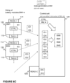
- Figures 6A-6E it is schematically illustrated non-limiting examples of setups based on the principle as disclosed in Figure 5 for determining the configuration of the battery pack in accordance with the present invention.
- the embodiments disclosed in Figure 6A-6E are as follows:
- Embodiments may also be used for determining number and / or configuration of other types of modules than battery cells and battery modules. Not only may it be used for battery system up to container level, but the same type of automatic configuration may be used for complete containers regardless of their content, for electronics in high numbers like diesel cylinder controllers, and in a system the configurations on many levels may simultaneously be automatically detected. From packages inside a container to strings of containers and all the way to a complete container ship or container harbour, the hierarchical physical location of every physical unit may be automatically detected.
- FIG. 7 illustrates a RFID module according to an example embodiment as a simplified block diagram.
- the RFID module comprises a processor 410 and a memory 420 storing data and computer program code 425.
- the RFID module may further comprise communication means 430, such as a communication interface, for wired or wireless communication with other apparatuses, such as with the control unit 150. and/or user I/O (input/output) components.
- the RFID module comprises at least RFID reader unit 114 comprising at least an antenna for communicating with one or more RFID tags 115 of other RFID modules.
- the RFID module may also comprise a RFID tag 115, but it may also be a separate entity to the RFID module.
- the mentioned entities in the RFID module may be communicatively coupled to each other via a bus 460 that enables transfer of data and control information between the components.
- the example of RFID module as illustrated in Figure 7 is a non-limiting example of the entity, and RFID modules having another implementation may be used to.
- both the RFID reader 114 and the RFID tag 115 of the same RFID module are schematically illustrated to reside in the same housing, but it may also be arranged that they are distinct entities arranged in the same battery cell 110 e.g. in a manner as schematically illustrated in Figure 1 .
- the battery modules 120 of the battery pack 100 may be a single RFID module, two or more RFID modules 115 arranged in a single physical location in the battery module 120 or in a plurality of locations both arrange to transmit the same identifier or different identifier.
- the control unit 150 may be associated with the battery modules 120 or it may be remotely located e.g.
- control unit 150 should be construed as a logical entity, that may be provided as one or more separate entities or components, some of which may be co-located with the other elements as e.g. depicted in the example of Figure 1 and some of which may be remotely located.
- the framework of Figure 1 is sufficient for description of various characteristics of solution for determining the configuration of the battery pack 100 according to the present disclosure.
- control unit 150 for one battery pack 100 there is arranged only one control unit 150.
- the present invention is not only limited to such an implementation.
- a battery pack 100 there may be a plurality of control units 150 each arranged to determine a configuration of a predetermined number of battery modules 120 belonging to the battery pack 100.
- the control units 150 may be arranged to communicate with each other, and it may e.g. be arranged to only one of the control units 150 is arranged to determine the configuration of the whole battery pack 100 e.g. for maintenance purposes.
- One preferred outcome of the solution according to the present invention is an ability of such a system to perform a determination of a configuration of a battery pack, and, hence, a location battery cells therein. This allows swapping of faulty units without the need of a manual configuration of the system.
Landscapes
- Engineering & Computer Science (AREA)
- Computer Networks & Wireless Communication (AREA)
- Physics & Mathematics (AREA)
- Theoretical Computer Science (AREA)
- Computer Hardware Design (AREA)
- Toxicology (AREA)
- Health & Medical Sciences (AREA)
- General Physics & Mathematics (AREA)
- Artificial Intelligence (AREA)
- Computer Vision & Pattern Recognition (AREA)
- General Health & Medical Sciences (AREA)
- Electromagnetism (AREA)
- Computer Security & Cryptography (AREA)
- Software Systems (AREA)
- General Engineering & Computer Science (AREA)
- Signal Processing (AREA)
- Battery Mounting, Suspending (AREA)
- Charge And Discharge Circuits For Batteries Or The Like (AREA)
Claims (15)
- Computerimplementiertes Verfahren zum Bestimmen einer Konfiguration eines Batteriepacks (100), das eine Vielzahl von Batteriemodulen (120) umfasst, die betriebsmäßig als eine Reihe von Batteriemodulen (120) verbunden sind, wobei das Verfahren, das von einer Steuereinheit (150) ausgeführt wird, Folgendes umfasst:Empfangen (320) erster Daten von einem ersten Batteriemodul (120; BM1), wobei die ersten Daten eine Modulkennung des ersten Batteriemoduls (120; BM1) umfassen, die mit zweiten Daten eines zweiten Batteriemoduls (120; BM2) verknüpft ist, das neben dem ersten Batteriemodul (120; BM1) liegt, wobei die zweiten Daten mindestens eine Modulkennung des zweiten Batteriemoduls (120; BM2) umfassen; undBestimmen (330) der Konfiguration des Batteriepacks (100) auf der Grundlage der ersten und zweiten Daten durch Erfassen einer Kennung eines Rahmenetiketts (610) als die vom ersten Batteriemodul (120) empfangenen zweiten Daten und Anwenden einer bekannten Position des Rahmenetiketts (610) in der Konfiguration des Batteriepacks (100) bei der Bestimmung (330).
- Computerimplementiertes Verfahren nach Anspruch 1, weiterhin umfassend:Empfangen von Daten, die eine Anzahl der zum Batteriepack (100) gehörenden Batteriemodule (110) angeben; undBestimmen der Konfiguration des Batteriepacks (100) unter Verwendung der Daten, die die Anzahl der zum Batteriepack (100) gehörenden Batteriemodule (110) angeben.
- Computerimplementiertes Verfahren nach Anspruch 1 oder Anspruch 2, wobei die Konfiguration des Batteriepacks (100) bestimmt wird (330), indem eine Kennung eines RFID-Kontrolllesers (620) als erste Daten erkannt wird und bei der Bestimmung (330) eine bekannte Position des RFID-Kontrolllesers (620) in der Konfiguration des Batteriepacks (100) berücksichtigt wird.
- Computerimplementiertes Verfahren nach einem der vorhergehenden Ansprüche, wobei die vom ersten Batteriemodul (120; BM1) empfangenen Daten weitere Daten umfassen, die mindestens eine weitere Kennung umfassen, die von mindestens einem weiteren Batteriemodul (120; BMn) empfangen wurde.
- Computerimplementiertes Verfahren nach einem der vorhergehenden Ansprüche, wobei die Konfiguration des Batteriepacks (100) durch Erkennen einer Kennung des RFID-Kontrolllesers (620) als erste Daten und durch Erkennen einer Kennung eines Rahmenetiketts (610) als zweite Daten, die von einem Batteriemodul (120) der Reihe von Batteriemodulen (120) empfangen werden, bestimmt wird.
- Computerimplementiertes Verfahren nach Anspruch 5, weiterhin umfassend:
Bestimmen von Daten, die eine Anzahl der Batteriemodule (120) angeben, die zu der Reihe von Batteriemodulen (120) gehören. - Computerimplementiertes Verfahren nach Anspruch 6, wobei die Konfiguration des Batteriepacks (100) durch Anwenden der Daten, die die Anzahl der Batteriemodule (110) angeben, bei der Bestimmung (330) bestimmt wird (330) .
- Steuereinheit (150) zum Bestimmen einer Konfiguration eines Batteriepacks (100), das eine Vielzahl von Batteriemodulen (120) umfasst, die betriebsmäßig als eine Reihe von Batteriemodulen (120) verbunden sind, wobei die Steuereinheit (150) Folgendes umfasst:mindestens einen Prozessor (210); undmindestens einen Speicher (220), der Computerprogrammcode (225) enthält;wobei der mindestens eine Speicher (220) und der Computerprogrammcode (225) so konfiguriert sind, dass sie zusammen mit dem mindestens einen Prozessor (210) die Steuereinheit (150) veranlassen:erste Daten von einem ersten Batteriemodul (120; BM1) zu empfangen (320), wobei die ersten Daten eine Modulkennung des ersten Batteriemoduls (120; BM1) umfassen, die mit zweiten Daten eines zweiten Batteriemoduls (120; BM2) verknüpft ist, das neben dem ersten Batteriemodul (120; BM1) liegt, wobei die zweiten Daten mindestens eine Modulkennung des zweiten Batteriemoduls (120; BM2) umfassen; unddie Konfiguration des Batteriepacks (100) basierend auf den ersten und zweiten Daten zu bestimmen (330), indem eine Kennung eines Rahmenetiketts (610) als die von dem ersten Batteriemodul (120) empfangenen zweiten Daten erkannt wird und eine bekannte Position des Rahmenetiketts (610) in der Konfiguration des Batteriepacks (100) bei der Bestimmung (330) angewendet wird.
- Steuereinheit (150) nach Anspruch 8, wobei die Steuereinheit (150) ferner dazu konfiguriert ist:Daten zu empfangen, die eine Anzahl der zum Batteriepack (100) gehörenden Batteriemodule (110) angeben; unddie Konfiguration des Batteriepacks (100) unter Verwendung der Daten zu bestimmen, die die Anzahl der zum Batteriepack (100) gehörenden Batteriemodule (110) angeben.
- Steuereinheit (150) nach Anspruch 8 oder Anspruch 9, wobei die Steuereinheit (150) dazu konfiguriert ist, die Konfiguration des Batteriepacks (100) zu bestimmen (330), indem sie als erste Daten eine Kennung eines RFID-Kontrolllesers (620) erkennt und bei der Bestimmung (330) eine bekannte Position des RFID-Kontrolllesers (620) in der Konfiguration des Batteriepacks (100) anwendet.
- Steuereinheit (150) nach einem der vorhergehenden Ansprüche 8 bis 10, wobei die Steuereinheit (150) dazu konfiguriert ist, weitere Daten vom ersten Batteriemodul (120; BM1) zu empfangen, wobei die weiteren Daten mindestens eine weitere Kennung umfassen, die von mindestens einem weiteren Batteriemodul (120; BMn) empfangen wurde.
- Steuereinheit (150) nach einem der Ansprüche 8 bis 11, weiterhin umfassend einen RFID-Steuerleser (620), wobei die Steuereinheit (150) so konfiguriert ist, dass sie die Konfiguration des Batteriepacks (100) durch Erkennen einer Kennung des RFID-Steuerlesers (620) als erste Daten und durch Erkennen einer Kennung eines Rahmenetiketts (610) als zweite Daten, die von einem Batteriemodul (120) der Reihe von Batteriemodulen (120) empfangen werden, bestimmt (330).
- Steuereinheit (150) nach Anspruch 12, wobei die Steuereinheit (150) dazu ausgebildet ist, Daten zu bestimmen, die eine Anzahl der zu der Reihe von Batteriemodulen (120) gehörenden Batteriemodule (120) angeben.
- Steuereinheit (150) nach Anspruch 13, wobei die Steuereinheit (150) dazu konfiguriert ist, die Konfiguration des Batteriepacks (100) zu bestimmen (330), indem sie bei der Bestimmung (330) die Daten anwendet, die die Anzahl der Batteriemodule (110) angeben.
- Computerprogramm, das auf einem computerlesbaren Medium verkörpert ist und computerausführbaren Programmcode umfasst, wobei der Code, wenn er von mindestens einem Prozessor einer Steuereinheit (150) ausgeführt wird, die Steuereinheit (150) dazu veranlasst:erste Daten von einem ersten Batteriemodul (120; BM1) zu empfangen (320), wobei die ersten Daten eine Modulkennung des ersten Batteriemoduls (120; BM1) umfassen, die mit zweiten Daten eines zweiten Batteriemoduls (120; BM2) verknüpft ist, das neben dem ersten Batteriemodul (120; BM1) liegt, wobei die zweiten Daten mindestens eine Modulkennung des zweiten Batteriemoduls (120; BM2) umfassen; undBestimmen (330) der Konfiguration des Batteriepacks (100) basierend auf den ersten und zweiten Daten durch Erfassen einer Kennung eines Rahmenetiketts (610) als die von dem ersten Batteriemodul (120) empfangenen zweiten Daten und Anwenden einer bekannten Position des Rahmenetiketts (610) in der Konfiguration des Batteriepacks (100) bei der Bestimmung (330).
Applications Claiming Priority (1)
| Application Number | Priority Date | Filing Date | Title |
|---|---|---|---|
| PCT/FI2019/050522 WO2021001593A1 (en) | 2019-07-02 | 2019-07-02 | Determination of a configuration of a battery pack |
Publications (2)
| Publication Number | Publication Date |
|---|---|
| EP3994894A1 EP3994894A1 (de) | 2022-05-11 |
| EP3994894B1 true EP3994894B1 (de) | 2024-11-13 |
Family
ID=67551563
Family Applications (1)
| Application Number | Title | Priority Date | Filing Date |
|---|---|---|---|
| EP19752210.5A Active EP3994894B1 (de) | 2019-07-02 | 2019-07-02 | Bestimmung einer konfiguration eines batteriepacks |
Country Status (3)
| Country | Link |
|---|---|
| US (1) | US12026121B2 (de) |
| EP (1) | EP3994894B1 (de) |
| WO (1) | WO2021001593A1 (de) |
Families Citing this family (5)
| Publication number | Priority date | Publication date | Assignee | Title |
|---|---|---|---|---|
| CN119894711A (zh) * | 2022-08-23 | 2025-04-25 | 亚德诺半导体国际无限责任公司 | 电动车辆电池组中的无线模块位置确认 |
| CN119698552B (zh) * | 2022-09-30 | 2026-03-03 | 宁德时代新能源科技股份有限公司 | 电池编码方法、装置、电子设备和电池 |
| US20240248148A1 (en) * | 2023-01-25 | 2024-07-25 | Caterpillar Inc. | Detection of battery pack mis-assembly |
| GB2633348A (en) * | 2023-09-06 | 2025-03-12 | Schlumberger Technology Bv | Measuring attachment for batteries |
| TWI888917B (zh) * | 2023-09-12 | 2025-07-01 | 車王電子股份有限公司 | 用於儲電系統的電池管理系統之複數個序碼的配置方法 |
Family Cites Families (33)
| Publication number | Priority date | Publication date | Assignee | Title |
|---|---|---|---|---|
| US20050136301A1 (en) * | 2003-12-19 | 2005-06-23 | Ballard Power Systems Inc. | Monitoring fuel cells using RFID devices |
| US20070008141A1 (en) * | 2005-07-11 | 2007-01-11 | Micropower Electronics Inc. | Battery identification system and method |
| US8341449B2 (en) * | 2010-04-16 | 2012-12-25 | Lg Chem, Ltd. | Battery management system and method for transferring data within the battery management system |
| US8616457B2 (en) * | 2010-11-22 | 2013-12-31 | Mark Stanley Krawczewicz | RFID display label for battery packs |
| JP5633745B2 (ja) * | 2011-02-15 | 2014-12-03 | ソニー株式会社 | 電池、電池パック、充電器、および充電システム |
| KR101768251B1 (ko) * | 2013-04-05 | 2017-08-30 | 삼성에스디아이 주식회사 | 배터리 모듈의 정상 연결 상태 확인을 제공하는 배터리 팩 |
| JP2014203719A (ja) * | 2013-04-08 | 2014-10-27 | 日立オートモティブシステムズ株式会社 | 車載バッテリー管理システム |
| KR101632350B1 (ko) * | 2013-09-09 | 2016-06-21 | 주식회사 엘지화학 | 멀티 bms에 대한 통신 식별자 할당 시스템 및 방법 |
| WO2015060576A1 (ko) * | 2013-10-25 | 2015-04-30 | 주식회사 엘지화학 | 적은 수의 절연소자를 사용하여 2차 보호 신호 및 진단 신호를 전송할 수 있는 배터리 관리 시스템 |
| JP6513711B2 (ja) * | 2014-02-24 | 2019-05-15 | エルジー・ケム・リミテッド | 周波数変調を用いて識別子を設定するバッテリー管理ユニット及び方法 |
| US9079505B1 (en) * | 2014-02-25 | 2015-07-14 | Elwah LLC | System and method for management of a fleet of vehicles having an energy storage system |
| US20150370745A1 (en) * | 2014-06-20 | 2015-12-24 | Key Systems, Inc. | System and method for communication port based asset management |
| US20160099590A1 (en) * | 2014-10-06 | 2016-04-07 | Black & Decker Inc. | System and method for renting, charging, and discharging battery packs |
| US9586541B2 (en) | 2015-02-25 | 2017-03-07 | GM Global Technology Operations LLC | Methods, apparatus, and systems for identification of cells in a network |
| KR102565272B1 (ko) * | 2016-01-04 | 2023-08-09 | 삼성전자주식회사 | 배터리 관리 방법 및 배터리 관리 장치 |
| GB2547502B (en) * | 2016-11-10 | 2018-05-02 | Tanktwo Oy | Detection of false reporting in a smart battery system |
| JP6819233B2 (ja) * | 2016-11-17 | 2021-01-27 | 株式会社オートネットワーク技術研究所 | 車両用のバッテリ監視システム |
| US20180175638A1 (en) * | 2016-12-15 | 2018-06-21 | Jiping Zhu | Method and system for smart battery and application thereof |
| KR102273785B1 (ko) * | 2017-01-24 | 2021-07-06 | 삼성에스디아이 주식회사 | 배터리 팩 관리 방법 및 시스템 |
| KR102101910B1 (ko) * | 2017-03-28 | 2020-04-17 | 주식회사 엘지화학 | 배터리 모듈의 id 중복 할당 방지방법 |
| KR102490869B1 (ko) * | 2017-06-08 | 2023-01-20 | 삼성에스디아이 주식회사 | 배터리 팩 진단 장치 및 방법 |
| KR102155331B1 (ko) * | 2017-07-06 | 2020-09-11 | 주식회사 엘지화학 | 무선 배터리 관리 시스템 및 이를 포함하는 배터리팩 |
| US11095662B2 (en) * | 2017-08-29 | 2021-08-17 | Amazon Technologies, Inc. | Federated messaging |
| US20190081372A1 (en) * | 2017-09-12 | 2019-03-14 | Sf Motors, Inc. | Modular battery system to provide power to electric vehicles |
| KR102129440B1 (ko) * | 2017-11-29 | 2020-07-08 | 주식회사 후본 | 연성회로기판에 기반한 통신 장치 |
| US11063445B2 (en) * | 2017-12-05 | 2021-07-13 | Green Cubes Technology, Llc | Multi-cell battery management device |
| KR102705897B1 (ko) * | 2019-08-05 | 2024-09-12 | 주식회사 엘지에너지솔루션 | 배터리 모듈의 자동 id 할당 시스템 및 방법 |
| CN113498142A (zh) * | 2020-03-18 | 2021-10-12 | 华为技术有限公司 | 一种中继通信方法及相关设备 |
| US11383616B2 (en) * | 2020-05-01 | 2022-07-12 | Nissan North America, Inc. | Vehicle battery life tracking system |
| US11509144B2 (en) * | 2020-06-02 | 2022-11-22 | Inventus Power, Inc. | Large-format battery management system with in-rush current protection for master-slave battery packs |
| US11436424B2 (en) * | 2021-01-19 | 2022-09-06 | City University Of Hong Kong | RFID-based sensing method and system |
| EP4033407B1 (de) * | 2021-01-26 | 2023-11-01 | Société BIC | Papierhandwerkliche digitalisierung |
| US11897362B2 (en) * | 2021-05-04 | 2024-02-13 | Exro Technologies Inc. | Systems and methods for individual control of a plurality of controllable units of battery cells |
-
2019
- 2019-07-02 EP EP19752210.5A patent/EP3994894B1/de active Active
- 2019-07-02 WO PCT/FI2019/050522 patent/WO2021001593A1/en not_active Ceased
-
2021
- 2021-12-30 US US17/566,270 patent/US12026121B2/en active Active
Also Published As
| Publication number | Publication date |
|---|---|
| EP3994894A1 (de) | 2022-05-11 |
| US20220121615A1 (en) | 2022-04-21 |
| WO2021001593A1 (en) | 2021-01-07 |
| US12026121B2 (en) | 2024-07-02 |
Similar Documents
| Publication | Publication Date | Title |
|---|---|---|
| US12026121B2 (en) | Determination of a configuration of a battery pack | |
| JP7649943B2 (ja) | 電池モニタシステム及び方法 | |
| EP2858267B1 (de) | Verfahren zur erkennung einer steckschnurverbindung und vorrichtung zur erkennung einer steckschnurverbindung | |
| KR20200024358A (ko) | 배터리 도난을 검출하기 위한 시스템 및 방법 | |
| CN102868442B (zh) | 一种基于rfid的光纤检测系统及检测方法 | |
| JP2020529104A (ja) | ワイヤレス可能にされたモノブロック | |
| CN107966692A (zh) | 一种具有自检功能的激光雷达 | |
| CN115825778A (zh) | 温度异常检测方法、装置、设备及存储介质 | |
| CN102917426A (zh) | 物联网终端的运营商网络切换方法及装置 | |
| US20140062385A1 (en) | Battery System and Method for Identifying Unauthorized Module Replacement in a Battery System | |
| KR20200034892A (ko) | 무선 통신 시스템에서 기지국의 방위각 결정 방법 및 장치 | |
| EP4050696A1 (de) | Batteriezellenpositionsbestimmung | |
| US20130086635A1 (en) | System and method for communication in a network | |
| US20200245148A1 (en) | Detection of internet-of-things devices in enterprise networks | |
| CN104219687A (zh) | 检测目标网络覆盖的方法及装置 | |
| CN119012153A (zh) | 一种机电伺服系统及其自诊断与测试方法 | |
| CN110161334A (zh) | 一种用于发送接收组件的老炼系统 | |
| CN105435873A (zh) | 一种移液针及移液设备 | |
| CN204463278U (zh) | 一种点巡检终端、标识设备和点巡检系统 | |
| CN119069843B (zh) | 基于近场无线通信的电池管理系统、电池通信控制方法、计算机可读存储介质及动力电池包 | |
| EP4075101B1 (de) | Datensammlung und analyse-basierte vorrichtungsüberwachung | |
| US20240369638A1 (en) | Vehicle battery cell counterfeit detection | |
| CN119030890A (zh) | 一种基于物联网技术的电网计量设备的数据监测系统 | |
| US20070081503A1 (en) | System and method for evaluating operation of a wireless device in a wireless network | |
| CN106207497A (zh) | 一种多波束天线系统及其构造波束的方法 |
Legal Events
| Date | Code | Title | Description |
|---|---|---|---|
| STAA | Information on the status of an ep patent application or granted ep patent |
Free format text: STATUS: UNKNOWN |
|
| STAA | Information on the status of an ep patent application or granted ep patent |
Free format text: STATUS: THE INTERNATIONAL PUBLICATION HAS BEEN MADE |
|
| PUAI | Public reference made under article 153(3) epc to a published international application that has entered the european phase |
Free format text: ORIGINAL CODE: 0009012 |
|
| STAA | Information on the status of an ep patent application or granted ep patent |
Free format text: STATUS: REQUEST FOR EXAMINATION WAS MADE |
|
| 17P | Request for examination filed |
Effective date: 20220131 |
|
| AK | Designated contracting states |
Kind code of ref document: A1 Designated state(s): AL AT BE BG CH CY CZ DE DK EE ES FI FR GB GR HR HU IE IS IT LI LT LU LV MC MK MT NL NO PL PT RO RS SE SI SK SM TR |
|
| DAV | Request for validation of the european patent (deleted) | ||
| DAX | Request for extension of the european patent (deleted) | ||
| GRAP | Despatch of communication of intention to grant a patent |
Free format text: ORIGINAL CODE: EPIDOSNIGR1 |
|
| GRAP | Despatch of communication of intention to grant a patent |
Free format text: ORIGINAL CODE: EPIDOSNIGR1 |
|
| STAA | Information on the status of an ep patent application or granted ep patent |
Free format text: STATUS: GRANT OF PATENT IS INTENDED |
|
| INTG | Intention to grant announced |
Effective date: 20240614 |
|
| GRAS | Grant fee paid |
Free format text: ORIGINAL CODE: EPIDOSNIGR3 |
|
| GRAA | (expected) grant |
Free format text: ORIGINAL CODE: 0009210 |
|
| STAA | Information on the status of an ep patent application or granted ep patent |
Free format text: STATUS: THE PATENT HAS BEEN GRANTED |
|
| AK | Designated contracting states |
Kind code of ref document: B1 Designated state(s): AL AT BE BG CH CY CZ DE DK EE ES FI FR GB GR HR HU IE IS IT LI LT LU LV MC MK MT NL NO PL PT RO RS SE SI SK SM TR |
|
| REG | Reference to a national code |
Ref country code: GB Ref legal event code: FG4D |
|
| REG | Reference to a national code |
Ref country code: CH Ref legal event code: EP |
|
| REG | Reference to a national code |
Ref country code: IE Ref legal event code: FG4D |
|
| REG | Reference to a national code |
Ref country code: DE Ref legal event code: R096 Ref document number: 602019061942 Country of ref document: DE |
|
| REG | Reference to a national code |
Ref country code: LT Ref legal event code: MG9D |
|
| REG | Reference to a national code |
Ref country code: NL Ref legal event code: MP Effective date: 20241113 |
|
| PG25 | Lapsed in a contracting state [announced via postgrant information from national office to epo] |
Ref country code: IS Free format text: LAPSE BECAUSE OF FAILURE TO SUBMIT A TRANSLATION OF THE DESCRIPTION OR TO PAY THE FEE WITHIN THE PRESCRIBED TIME-LIMIT Effective date: 20250313 Ref country code: PT Free format text: LAPSE BECAUSE OF FAILURE TO SUBMIT A TRANSLATION OF THE DESCRIPTION OR TO PAY THE FEE WITHIN THE PRESCRIBED TIME-LIMIT Effective date: 20250313 Ref country code: HR Free format text: LAPSE BECAUSE OF FAILURE TO SUBMIT A TRANSLATION OF THE DESCRIPTION OR TO PAY THE FEE WITHIN THE PRESCRIBED TIME-LIMIT Effective date: 20241113 |
|
| PG25 | Lapsed in a contracting state [announced via postgrant information from national office to epo] |
Ref country code: NL Free format text: LAPSE BECAUSE OF FAILURE TO SUBMIT A TRANSLATION OF THE DESCRIPTION OR TO PAY THE FEE WITHIN THE PRESCRIBED TIME-LIMIT Effective date: 20241113 Ref country code: FI Free format text: LAPSE BECAUSE OF FAILURE TO SUBMIT A TRANSLATION OF THE DESCRIPTION OR TO PAY THE FEE WITHIN THE PRESCRIBED TIME-LIMIT Effective date: 20241113 |
|
| REG | Reference to a national code |
Ref country code: AT Ref legal event code: MK05 Ref document number: 1742564 Country of ref document: AT Kind code of ref document: T Effective date: 20241113 |
|
| PG25 | Lapsed in a contracting state [announced via postgrant information from national office to epo] |
Ref country code: BG Free format text: LAPSE BECAUSE OF FAILURE TO SUBMIT A TRANSLATION OF THE DESCRIPTION OR TO PAY THE FEE WITHIN THE PRESCRIBED TIME-LIMIT Effective date: 20241113 |
|
| PG25 | Lapsed in a contracting state [announced via postgrant information from national office to epo] |
Ref country code: ES Free format text: LAPSE BECAUSE OF FAILURE TO SUBMIT A TRANSLATION OF THE DESCRIPTION OR TO PAY THE FEE WITHIN THE PRESCRIBED TIME-LIMIT Effective date: 20241113 |
|
| PG25 | Lapsed in a contracting state [announced via postgrant information from national office to epo] |
Ref country code: NO Free format text: LAPSE BECAUSE OF FAILURE TO SUBMIT A TRANSLATION OF THE DESCRIPTION OR TO PAY THE FEE WITHIN THE PRESCRIBED TIME-LIMIT Effective date: 20250213 |
|
| PG25 | Lapsed in a contracting state [announced via postgrant information from national office to epo] |
Ref country code: GR Free format text: LAPSE BECAUSE OF FAILURE TO SUBMIT A TRANSLATION OF THE DESCRIPTION OR TO PAY THE FEE WITHIN THE PRESCRIBED TIME-LIMIT Effective date: 20250214 Ref country code: AT Free format text: LAPSE BECAUSE OF FAILURE TO SUBMIT A TRANSLATION OF THE DESCRIPTION OR TO PAY THE FEE WITHIN THE PRESCRIBED TIME-LIMIT Effective date: 20241113 Ref country code: LV Free format text: LAPSE BECAUSE OF FAILURE TO SUBMIT A TRANSLATION OF THE DESCRIPTION OR TO PAY THE FEE WITHIN THE PRESCRIBED TIME-LIMIT Effective date: 20241113 |
|
| PG25 | Lapsed in a contracting state [announced via postgrant information from national office to epo] |
Ref country code: PL Free format text: LAPSE BECAUSE OF FAILURE TO SUBMIT A TRANSLATION OF THE DESCRIPTION OR TO PAY THE FEE WITHIN THE PRESCRIBED TIME-LIMIT Effective date: 20241113 |
|
| PG25 | Lapsed in a contracting state [announced via postgrant information from national office to epo] |
Ref country code: RS Free format text: LAPSE BECAUSE OF FAILURE TO SUBMIT A TRANSLATION OF THE DESCRIPTION OR TO PAY THE FEE WITHIN THE PRESCRIBED TIME-LIMIT Effective date: 20250213 |
|
| PG25 | Lapsed in a contracting state [announced via postgrant information from national office to epo] |
Ref country code: SM Free format text: LAPSE BECAUSE OF FAILURE TO SUBMIT A TRANSLATION OF THE DESCRIPTION OR TO PAY THE FEE WITHIN THE PRESCRIBED TIME-LIMIT Effective date: 20241113 |
|
| PG25 | Lapsed in a contracting state [announced via postgrant information from national office to epo] |
Ref country code: DK Free format text: LAPSE BECAUSE OF FAILURE TO SUBMIT A TRANSLATION OF THE DESCRIPTION OR TO PAY THE FEE WITHIN THE PRESCRIBED TIME-LIMIT Effective date: 20241113 |
|
| PG25 | Lapsed in a contracting state [announced via postgrant information from national office to epo] |
Ref country code: EE Free format text: LAPSE BECAUSE OF FAILURE TO SUBMIT A TRANSLATION OF THE DESCRIPTION OR TO PAY THE FEE WITHIN THE PRESCRIBED TIME-LIMIT Effective date: 20241113 |
|
| PG25 | Lapsed in a contracting state [announced via postgrant information from national office to epo] |
Ref country code: RO Free format text: LAPSE BECAUSE OF FAILURE TO SUBMIT A TRANSLATION OF THE DESCRIPTION OR TO PAY THE FEE WITHIN THE PRESCRIBED TIME-LIMIT Effective date: 20241113 |
|
| PG25 | Lapsed in a contracting state [announced via postgrant information from national office to epo] |
Ref country code: SK Free format text: LAPSE BECAUSE OF FAILURE TO SUBMIT A TRANSLATION OF THE DESCRIPTION OR TO PAY THE FEE WITHIN THE PRESCRIBED TIME-LIMIT Effective date: 20241113 |
|
| PG25 | Lapsed in a contracting state [announced via postgrant information from national office to epo] |
Ref country code: CZ Free format text: LAPSE BECAUSE OF FAILURE TO SUBMIT A TRANSLATION OF THE DESCRIPTION OR TO PAY THE FEE WITHIN THE PRESCRIBED TIME-LIMIT Effective date: 20241113 |
|
| PG25 | Lapsed in a contracting state [announced via postgrant information from national office to epo] |
Ref country code: IT Free format text: LAPSE BECAUSE OF FAILURE TO SUBMIT A TRANSLATION OF THE DESCRIPTION OR TO PAY THE FEE WITHIN THE PRESCRIBED TIME-LIMIT Effective date: 20241113 |
|
| REG | Reference to a national code |
Ref country code: DE Ref legal event code: R097 Ref document number: 602019061942 Country of ref document: DE |
|
| PG25 | Lapsed in a contracting state [announced via postgrant information from national office to epo] |
Ref country code: SE Free format text: LAPSE BECAUSE OF FAILURE TO SUBMIT A TRANSLATION OF THE DESCRIPTION OR TO PAY THE FEE WITHIN THE PRESCRIBED TIME-LIMIT Effective date: 20241113 |
|
| PLBE | No opposition filed within time limit |
Free format text: ORIGINAL CODE: 0009261 |
|
| STAA | Information on the status of an ep patent application or granted ep patent |
Free format text: STATUS: NO OPPOSITION FILED WITHIN TIME LIMIT |
|
| 26N | No opposition filed |
Effective date: 20250814 |
|
| REG | Reference to a national code |
Ref country code: DE Ref legal event code: R119 Ref document number: 602019061942 Country of ref document: DE |
|
| REG | Reference to a national code |
Ref country code: CH Ref legal event code: H13 Free format text: ST27 STATUS EVENT CODE: U-0-0-H10-H13 (AS PROVIDED BY THE NATIONAL OFFICE) Effective date: 20260224 |
|
| PG25 | Lapsed in a contracting state [announced via postgrant information from national office to epo] |
Ref country code: LU Free format text: LAPSE BECAUSE OF NON-PAYMENT OF DUE FEES Effective date: 20250702 |
|
| GBPC | Gb: european patent ceased through non-payment of renewal fee |
Effective date: 20250702 |
|
| REG | Reference to a national code |
Ref country code: BE Ref legal event code: MM Effective date: 20250731 |
|
| PG25 | Lapsed in a contracting state [announced via postgrant information from national office to epo] |
Ref country code: GB Free format text: LAPSE BECAUSE OF NON-PAYMENT OF DUE FEES Effective date: 20250702 |
|
| PG25 | Lapsed in a contracting state [announced via postgrant information from national office to epo] |
Ref country code: DE Free format text: LAPSE BECAUSE OF NON-PAYMENT OF DUE FEES Effective date: 20260203 |
|
| PG25 | Lapsed in a contracting state [announced via postgrant information from national office to epo] |
Ref country code: BE Free format text: LAPSE BECAUSE OF NON-PAYMENT OF DUE FEES Effective date: 20250731 |
|
| PG25 | Lapsed in a contracting state [announced via postgrant information from national office to epo] |
Ref country code: FR Free format text: LAPSE BECAUSE OF NON-PAYMENT OF DUE FEES Effective date: 20250731 |