EP3995103A2 - Implantatpfosten - Google Patents
Implantatpfosten Download PDFInfo
- Publication number
- EP3995103A2 EP3995103A2 EP20834687.4A EP20834687A EP3995103A2 EP 3995103 A2 EP3995103 A2 EP 3995103A2 EP 20834687 A EP20834687 A EP 20834687A EP 3995103 A2 EP3995103 A2 EP 3995103A2
- Authority
- EP
- European Patent Office
- Prior art keywords
- abutment
- slight movement
- seating
- movement part
- end portion
- Prior art date
- Legal status (The legal status is an assumption and is not a legal conclusion. Google has not performed a legal analysis and makes no representation as to the accuracy of the status listed.)
- Withdrawn
Links
- 239000007943 implant Substances 0.000 title claims abstract description 49
- 230000008878 coupling Effects 0.000 claims description 24
- 238000010168 coupling process Methods 0.000 claims description 24
- 238000005859 coupling reaction Methods 0.000 claims description 24
- 239000002861 polymer material Substances 0.000 claims description 12
- 229920001169 thermoplastic Polymers 0.000 claims description 12
- 238000003780 insertion Methods 0.000 claims description 10
- 230000037431 insertion Effects 0.000 claims description 10
- 239000000853 adhesive Substances 0.000 claims description 8
- 230000001070 adhesive effect Effects 0.000 claims description 8
- 239000011800 void material Substances 0.000 claims description 8
- 239000004721 Polyphenylene oxide Substances 0.000 claims description 6
- 229920000570 polyether Polymers 0.000 claims description 6
- JOYRKODLDBILNP-UHFFFAOYSA-N Ethyl urethane Chemical compound CCOC(N)=O JOYRKODLDBILNP-UHFFFAOYSA-N 0.000 claims description 3
- 229920003171 Poly (ethylene oxide) Polymers 0.000 claims description 3
- NBVXSUQYWXRMNV-UHFFFAOYSA-N fluoromethane Chemical compound FC NBVXSUQYWXRMNV-UHFFFAOYSA-N 0.000 claims description 3
- 239000004033 plastic Substances 0.000 claims description 3
- 229920003023 plastic Polymers 0.000 claims description 3
- 239000004417 polycarbonate Substances 0.000 claims description 3
- 229920000515 polycarbonate Polymers 0.000 claims description 3
- 229920001296 polysiloxane Polymers 0.000 claims description 3
- 229920002635 polyurethane Polymers 0.000 claims description 3
- 239000004814 polyurethane Substances 0.000 claims description 3
- 210000000988 bone and bone Anatomy 0.000 description 6
- 230000018984 mastication Effects 0.000 description 5
- 238000010077 mastication Methods 0.000 description 5
- 230000000740 bleeding effect Effects 0.000 description 3
- 230000023555 blood coagulation Effects 0.000 description 3
- 210000001738 temporomandibular joint Anatomy 0.000 description 3
- 206010061218 Inflammation Diseases 0.000 description 2
- 230000000694 effects Effects 0.000 description 2
- 230000004054 inflammatory process Effects 0.000 description 2
- 210000004746 tooth root Anatomy 0.000 description 2
- 238000010521 absorption reaction Methods 0.000 description 1
- 239000008280 blood Substances 0.000 description 1
- 210000004369 blood Anatomy 0.000 description 1
- 230000036760 body temperature Effects 0.000 description 1
- 235000021059 hard food Nutrition 0.000 description 1
- 210000004373 mandible Anatomy 0.000 description 1
- 239000000463 material Substances 0.000 description 1
- 210000002050 maxilla Anatomy 0.000 description 1
- 238000000034 method Methods 0.000 description 1
- 238000012986 modification Methods 0.000 description 1
- 230000004048 modification Effects 0.000 description 1
- 210000000214 mouth Anatomy 0.000 description 1
- 210000002379 periodontal ligament Anatomy 0.000 description 1
Images





Classifications
-
- A—HUMAN NECESSITIES
- A61—MEDICAL OR VETERINARY SCIENCE; HYGIENE
- A61C—DENTISTRY; APPARATUS OR METHODS FOR ORAL OR DENTAL HYGIENE
- A61C8/00—Means to be fixed to the jaw-bone for consolidating natural teeth or for fixing dental prostheses thereon; Dental implants; Implanting tools
- A61C8/0086—Means to be fixed to the jaw-bone for consolidating natural teeth or for fixing dental prostheses thereon; Dental implants; Implanting tools with shock absorbing means
-
- A—HUMAN NECESSITIES
- A61—MEDICAL OR VETERINARY SCIENCE; HYGIENE
- A61C—DENTISTRY; APPARATUS OR METHODS FOR ORAL OR DENTAL HYGIENE
- A61C8/00—Means to be fixed to the jaw-bone for consolidating natural teeth or for fixing dental prostheses thereon; Dental implants; Implanting tools
-
- A—HUMAN NECESSITIES
- A61—MEDICAL OR VETERINARY SCIENCE; HYGIENE
- A61C—DENTISTRY; APPARATUS OR METHODS FOR ORAL OR DENTAL HYGIENE
- A61C8/00—Means to be fixed to the jaw-bone for consolidating natural teeth or for fixing dental prostheses thereon; Dental implants; Implanting tools
- A61C8/0012—Means to be fixed to the jaw-bone for consolidating natural teeth or for fixing dental prostheses thereon; Dental implants; Implanting tools characterised by the material or composition, e.g. ceramics, surface layer, metal alloy
- A61C8/0016—Means to be fixed to the jaw-bone for consolidating natural teeth or for fixing dental prostheses thereon; Dental implants; Implanting tools characterised by the material or composition, e.g. ceramics, surface layer, metal alloy polymeric material
-
- A—HUMAN NECESSITIES
- A61—MEDICAL OR VETERINARY SCIENCE; HYGIENE
- A61C—DENTISTRY; APPARATUS OR METHODS FOR ORAL OR DENTAL HYGIENE
- A61C8/00—Means to be fixed to the jaw-bone for consolidating natural teeth or for fixing dental prostheses thereon; Dental implants; Implanting tools
- A61C8/0018—Means to be fixed to the jaw-bone for consolidating natural teeth or for fixing dental prostheses thereon; Dental implants; Implanting tools characterised by the shape
- A61C8/0037—Details of the shape
- A61C8/0042—Details of the shape consisting of two halves
-
- A—HUMAN NECESSITIES
- A61—MEDICAL OR VETERINARY SCIENCE; HYGIENE
- A61C—DENTISTRY; APPARATUS OR METHODS FOR ORAL OR DENTAL HYGIENE
- A61C8/00—Means to be fixed to the jaw-bone for consolidating natural teeth or for fixing dental prostheses thereon; Dental implants; Implanting tools
- A61C8/0018—Means to be fixed to the jaw-bone for consolidating natural teeth or for fixing dental prostheses thereon; Dental implants; Implanting tools characterised by the shape
- A61C8/0037—Details of the shape
- A61C8/0045—Details of the shape with a stepped body
-
- A—HUMAN NECESSITIES
- A61—MEDICAL OR VETERINARY SCIENCE; HYGIENE
- A61C—DENTISTRY; APPARATUS OR METHODS FOR ORAL OR DENTAL HYGIENE
- A61C8/00—Means to be fixed to the jaw-bone for consolidating natural teeth or for fixing dental prostheses thereon; Dental implants; Implanting tools
- A61C8/0048—Connecting the upper structure to the implant, e.g. bridging bars
- A61C8/005—Connecting devices for joining an upper structure with an implant member, e.g. spacers
- A61C8/006—Connecting devices for joining an upper structure with an implant member, e.g. spacers with polygonal positional means, e.g. hexagonal or octagonal
-
- A—HUMAN NECESSITIES
- A61—MEDICAL OR VETERINARY SCIENCE; HYGIENE
- A61C—DENTISTRY; APPARATUS OR METHODS FOR ORAL OR DENTAL HYGIENE
- A61C8/00—Means to be fixed to the jaw-bone for consolidating natural teeth or for fixing dental prostheses thereon; Dental implants; Implanting tools
- A61C8/0048—Connecting the upper structure to the implant, e.g. bridging bars
- A61C8/005—Connecting devices for joining an upper structure with an implant member, e.g. spacers
- A61C8/0062—Catch or snap type connection
-
- A—HUMAN NECESSITIES
- A61—MEDICAL OR VETERINARY SCIENCE; HYGIENE
- A61C—DENTISTRY; APPARATUS OR METHODS FOR ORAL OR DENTAL HYGIENE
- A61C8/00—Means to be fixed to the jaw-bone for consolidating natural teeth or for fixing dental prostheses thereon; Dental implants; Implanting tools
- A61C8/0048—Connecting the upper structure to the implant, e.g. bridging bars
- A61C8/005—Connecting devices for joining an upper structure with an implant member, e.g. spacers
- A61C8/0063—Connecting devices for joining an upper structure with an implant member, e.g. spacers with an internal sleeve
-
- A—HUMAN NECESSITIES
- A61—MEDICAL OR VETERINARY SCIENCE; HYGIENE
- A61C—DENTISTRY; APPARATUS OR METHODS FOR ORAL OR DENTAL HYGIENE
- A61C8/00—Means to be fixed to the jaw-bone for consolidating natural teeth or for fixing dental prostheses thereon; Dental implants; Implanting tools
- A61C8/0048—Connecting the upper structure to the implant, e.g. bridging bars
- A61C8/005—Connecting devices for joining an upper structure with an implant member, e.g. spacers
- A61C8/0065—Connecting devices for joining an upper structure with an implant member, e.g. spacers with expandable or compressible means
Definitions
- the present invention relates to an implant abutment.
- an implant refers to technique in which, by placing an artificial substitute in the maxilla and mandible to replace a lost tooth, the overall function of the oral cavity and teeth is restored.
- the implant has been widely used in recent years due to having various advantages in that it may not require removal of a target tooth or an adjacent tooth, it is able to minimize inconvenience caused by detachment such as when using a denture, and it allows a dental prosthesis to be maintained and have high stability, thus improving a masticatory function.
- the implant mainly consists of a fixture, an abutment, and a dental prosthesis disposed at the top.
- the fixture is a portion corresponding to a dental root of a natural tooth that is buried in an alveolar bone and fixed
- the abutment is a portion that connects the fixture and the dental prosthesis disposed at the top.
- a lower portion of the abutment is coupled to the fixture by a coupling part and is disposed inside the gum
- an upper portion of the abutment is a portion that is exposed above the gum and coupled to the dental prosthesis disposed at the top.
- the implant has a limitation in that it is an artificial substitute, and thus it is difficult for the implant to realize the same oral environment as a natural tooth.
- a periodontal ligament surrounds a dental root, and thus an external impact such as a masticatory pressure is absorbed, and a force received from the outside is balanced by slight movement of the tooth.
- an implant since a fixture placed in an alveolar bone does not move at all, there is a problem in that absorption of external impact, proper distribution of masticatory pressure, and the like similar to those of a natural tooth cannot be expected.
- the present invention provides an implant structure that is capable of absorbing a masticatory pressure so that the masticatory pressure is not transmitted to an alveolar bone and a jawbone or a temporomandibular joint and that has a slight movement part interposed on an abutment to implement slight movement during mastication like a natural tooth.
- One embodiment of the present invention provides an implant structure which is an implant abutment for connecting a fixture and a dental prosthesis, the implant abutment including an abutment lower part coupled to the fixture, an abutment upper part coupled to the dental prosthesis, and a slight movement part interposed between the abutment upper part and the abutment lower part or interposed on a portion of the abutment upper part or the entire abutment upper part, wherein the abutment lower part and the abutment upper part are integrally formed or are separately formed and coupled to each other.
- the slight movement part may be made of a thermoplastic polymer material.
- thermoplastic polymer material may be any one of silicone, polyurethane, polycarbonate, polyether urethane, polyethylene oxide, fluorocarbon, and polyether or a combination of two or more thereof.
- the thermoplastic polymer material may cause plastic deformation in a temperature in a range of 25 °C to 70 °C.
- the slight movement part may be a filled column or a void column whose central portion is hollow.
- an upper end portion of the abutment lower part or a lower end portion of the abutment upper part may include a fixing part which has a diameter smaller than a diameter of the upper end portion or the lower end portion and protrudes upward or downward and a fixing part insertion groove which corresponds to a protruding length and the diameter of the fixing part, the slight movement part may be a void cylinder whose central portion is hollow, and the fixing part may be coupled to the fixing part insertion groove via the void of the slight movement part.
- the slight movement part may include a protruding step which is disposed at a central portion of a side surface of the cylinder and has a diameter larger than that of a bottom surface of the cylinder, the upper end portion of the abutment lower part or the lower end portion of the abutment upper part may include a seating step which is an outer edge higher than a seating part which is an upper end surface or a lower end surface excluding the fixing part, and the protruding step of the slight movement part may be seated on the seating step while the bottom surface of the cylinder of the slight movement part is seated on the seating part.
- the slight movement part may include a concave joining base disposed at the bottom surface of the cylinder
- the upper end portion of the abutment lower part may include a convex seating step which is disposed at a central portion of the seating part, which is the upper end surface excluding the fixing part, and higher than the seating part
- the concave joining base of the slight movement part may be coupled to the convex seating step by being fitted thereto or by using an adhesive.
- the slight movement part may be a filled cylinder and may include a protruding step which is disposed at a central portion of a side surface of the cylinder and has a diameter larger than that of a bottom surface of the cylinder
- the upper end portion of the abutment lower part may include a lower seating step which is an outer edge higher than an upper seating part which is an upper end surface
- the lower end portion of the abutment upper part may include an upper seating step which is an outer edge higher than a lower seating part which is a lower end surface
- the protruding step of the slight movement part may be seated on the upper and lower seating steps while the bottom surface of the cylinder of the slight movement part is seated on the upper and lower seating parts.
- the slight movement part may surround the abutment upper part.
- a slight movement part coupling groove may be formed in an upper end surface of the abutment upper part, the slight movement part may be coupled to the upper end surface of the abutment upper part and may include a fixing part which is disposed at a lower end portion of the slight movement part and protrudes with a diameter smaller than that of a lower end surface, and the fixing part may be seated on the slight movement part coupling groove.
- a slight movement part interposed on an abutment due to a slight movement part interposed on an abutment, slight movement of a natural tooth can be implemented, and a masticatory pressure can be absorbed so as not to be transmitted to an alveolar bone and a jawbone or a temporomandibular joint.
- the slight movement part which absorbs impact or distributes force can prevent a dental prosthesis from being easily broken.
- first and second may be used to describe various embodiments, but the elements are not limited b such terms. The terms are only used for the purpose of distinguishing one element from another element. For example, without departing from the scope of the present invention, “first element” may be referred to as “second element,” and likewise, “second element” may also be referred to as “first element.” Also, a singular expression includes a plural expression unless the context clearly indicates otherwise. Unless defined otherwise, the terms used in the embodiments of the present invention may be interpreted as having a meaning commonly known by those of ordinary skill in the art.
- FIGS. 1 to 10 an implant structure according to an embodiment of the present invention will be described with reference to FIGS. 1 to 10 .
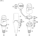
- FIG. 1 is an exemplary view for describing a configuration of the implant structure according to the embodiment of the present invention.
- FIG. 1A is a coupling view
- FIG. 1B is a vertical cross-sectional view
- FIG. 1C is an exploded perspective view.
- an abutment in the implant structure according to the embodiment of the present invention, includes an abutment upper part 10, a slight movement part 20, an abutment lower part 30, and a coupling part 40 which is coupled to a fixture placed in an alveolar bone.
- the abutment lower part 30 is disposed inside the gum, and the abutment upper part 10 is exposed above the gum and coupled to a dental prosthesis.
- the same may apply for the following description of each embodiment, and thus description thereof will be omitted to avoid repeated description.
- a fixing part 30a is disposed at an upper end surface of the abutment lower part 30 so as to be coupled to the abutment upper part 10.
- the fixing part 30a has a structure that protrudes upward with a diameter smaller than a diameter of the upper end surface of the abutment lower part 30, and a fixing part insertion groove which corresponds to a protruding length of the fixing part 30a and the diameter thereof is formed in a lower end surface of the abutment upper part 10 to allow coupling to the fixing part 30a.
- a surface of the fixing part 30a may be implemented to have a polygonal structure 30c so as to be fitted and coupled to the fixing part insertion groove of the abutment upper part 10 without being detached therefrom.
- the slight movement part 20 is interposed between the lower end surface of the abutment upper part 10 and the upper end surface of the abutment lower part 30.
- the slight movement part 20 slightly moves the implant structure in response to a masticatory pressure during mastication. Due to slight movement of the implant structure, the masticatory pressure is prevented from being transmitted to a jawbone and a temporomandibular joint, and thus the dental prosthesis may be prevented from being broken, and slight movement similar to that of a natural tooth may be implemented.
- the slight movement part 20 may be made of a thermoplastic polymer material.
- the thermoplastic polymer material has a characteristic of softening at a specific temperature but hardening at temperatures other than the specific temperature.
- the thermoplastic polymer material constituting the slight movement part 20 of the present invention one of silicone, polyurethane, polycarbonate, polyether urethane, polyethylene oxide, fluorocarbon, and polyether or a combination of two or more thereof may be used. Due to having a property of causing plastic deformation a temperature in a range of 25 °C to 70 °C, the thermoplastic polymer material may, when placed in the gum, soften at human body temperature and cause the abutment to slight move during mastication.
- the implant structure due to being placed in an alveolar bone, the implant structure often causes inflammation or bleeding of the gum or inside the gum.
- inflammation may occur, and the implant may have to be replaced, or even when not replaced, the implant may be unable to properly perform its function.
- the thermoplastic polymer material of the present invention is highly resistant to blood clotting, and thus, even when bleeding occurs in the gum or the like, the possibility of an occurrence of blood clotting after blood adheres to the material is extremely low. Accordingly, slight movement of the thermoplastic polymer material itself is possible during mastication.
- the slight movement part 20 has a cylindrical shape and is formed as a void to allow the fixing part 30a of the abutment lower part to pass therethrough.
- a seating part 30e excluding the fixing part is disposed at an upper end portion of the abutment lower part, and the slight movement part 20 is seated on the seating part 30e and coupled to the abutment lower part 30.
- a contact portion 30d of the fixing part 30a that comes into contact with the inside of the void of the slight movement part 20 has a circular structure, instead of a polygonal structure, in order to come in close contact with the slight movement part 20.
- the slight movement part 20 is coupled to the seating part 30e of the abutment lower part and the abutment upper part 10 by an adhesive.
- the slight movement part 20 is illustrated as having a circular shape, but the shape of the slight movement part 20 is not limited thereto.
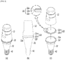
- FIG. 2 is an exemplary view for describing a configuration of an abutment of an implant structure according to another embodiment of the present invention.
- FIG. 2A is a coupling view
- FIG. 2B is a vertical cross-sectional view
- FIG. 2C is an exploded perspective view. Description of elements identical to those of FIG. 1 will be omitted.
- a slight movement part 21 is interposed between an abutment lower part 31 and an abutment upper part 11.
- the slight movement part 21 of the present invention has a hollow cylindrical shape and includes a protruding step 21b which is disposed at a central portion of a side surface of the cylinder and has a diameter larger than that of a bottom surface 21a of the cylinder.
- a fixing part 31a of the abutment lower part protrudes to be coupled to the abutment upper part 11, and a polygonal structure 31c for coupling to the abutment upper part 11 is the same as in FIG. 1C .
- a seating step 31f which is an outer edge higher than a seating part 31e which is an upper end surface excluding the fixing part is formed at an upper end portion of the abutment lower part.
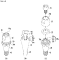
- FIG. 3 is an exemplary view for describing a configuration of an abutment of an implant structure according to another embodiment of the present invention.
- FIG. 3A is a coupling view
- FIG. 3B is a vertical cross-sectional view
- FIG. 3C is an exploded perspective view. Description of elements identical to those of FIG. 1 will be omitted.
- a slight movement part 22 is interposed between an upper end portion of an abutment lower part 32 and a lower end portion of an abutment upper part 12.
- the slight movement part 22 of the present invention has a filled cylindrical shape and includes a protruding step 22b which is disposed at a central portion of a side surface of the cylinder and has a diameter larger than that of a bottom surface 22a of the cylinder.
- a seating part 32e of the abutment lower part on which the slight movement part 22 is seated is formed to be lower than a lower seating step 32f which is an edge.
- An upper seating step (not illustrated) which is an outer edge higher than the seating part which is a lower end surface is formed at a lower end portion of the abutment upper part 12, the bottom surface 22a of the slight movement part 22 is seated on an upper seating part, and the protruding step 22b of the slight movement part is interposed to correspond to the upper seating step.
- an adhesive when interposing the slight movement part 22 between the abutment lower part and the lower end portion of the abutment upper part is the same as described above with reference to FIG. 1 .
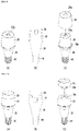
- FIG. 4 is an exemplary view for describing a configuration of an abutment of an implant structure according to another embodiment of the present invention.
- FIG. 4A is a coupling view
- FIG. 4B is a vertical cross-sectional view
- FIG. 4C is an exploded perspective view. Description of elements identical to those of FIG. 1 or 2 will be omitted.
- a tool insertion groove 13g to which a tool is fastened upon placement may be formed in an upper end portion of an abutment upper part 13.
- Other configurations are the same as in FIG. 2 , and thus detailed description thereof will be omitted.
- FIG. 5 is an exemplary view for describing a configuration of an abutment of an implant structure according to another embodiment of the present invention.
- FIG. 5A is a coupling view
- FIG. 5B is a vertical cross-sectional view
- FIG. 5C is an exploded perspective view.
- a slight movement part 24 is interposed between an abutment lower part 34 and a lower end portion of an abutment upper part 14.
- the slight movement part 24 of the present invention has a hollow cylindrical shape and includes a protruding step 24b which is disposed at a central portion of a side surface of the cylinder and has a diameter larger than that of a bottom surface 24a of the cylinder.
- a fixing part 14a is disposed at the lower end portion of the abutment upper part 14, has a protruding shape so as to be coupled to the abutment lower part 34, and has a polygonal structure 14c for coupling to the abutment lower part 34.
- a seating part 34e of the abutment lower part is formed to be lower than a slight movement part seating step 34f which is an edge of the seating part 34e.
- FIG. 6 is an exemplary view for describing a configuration of an abutment of an implant structure according to another embodiment of the present invention.
- FIG. 6A is a coupling view
- FIG. 6B is a vertical cross-sectional view
- FIG. 6C is an exploded perspective view.
- an upper end portion of an abutment lower part 35 has a fixing part 35a, and the fixing part has a protruding shape so as to be coupled to an abutment upper part 15 and has a polygonal structure 35c for coupling to the abutment upper part 15. Meanwhile, at a central portion of a seating part 35e, which is an upper end surface excluding the fixing part, a convex seating step 35f higher than the seating part is disposed. Also, the fixing part 35a has a diameter smaller than a diameter of the abutment lower part 35.
- a slight movement part 25 has a hollow cylindrical shape and includes a concave joining base 25a disposed at a bottom surface of the cylinder.
- the concave joining base 25a is fitted to the convex seating step 35f of the abutment lower part.
- the concave joining base 25a may also be coupled to the convex seating step 35f using an adhesive.
- a screw insertion groove 15g to which a screw 55 may be coupled may be formed in a surface of the abutment upper part 15.
- FIG. 7 is an exemplary view for describing a configuration of an abutment of an implant structure according to another embodiment of the present invention.
- FIG. 7A is a coupling view
- FIG. 7B is a vertical cross-sectional view
- FIG. 7C is an exploded perspective view.
- a slight movement part 26 of the present invention has a filled cylindrical shape and includes a protruding step 26b which is disposed at a central portion of a side surface of the cylinder and has a diameter larger than that of a bottom surface 26a of the cylinder.
- an abutment upper part 16 and an abutment lower part 36 have fixing parts 56 and 66, respectively.
- the fixing parts 56 and 66 include slight movement part seating parts 56e and 66e and coupling screws 56c and 66c.
- the bottom surface 26a of the slight movement part 26 is seated on the seating parts 56e and 66e and coupled thereto, and the coupling screws 56c and 66c are coupled to the abutment upper part 16 and the abutment lower part 36 through screw fasteners 36g and 56g.
- the seating parts 56e and 66e of the abutment lower part on which the slight movement part 26 is seated are formed to be lower than slight movement part seating steps 56f and 66f which are edges.
- the bottom surface 26a of the slight movement part 26 is seated on the seating parts 56e and 66e, and the protruding step 26b of the slight movement part is interposed to correspond to the seating steps 56f and 66f.
- An adhesive is used when interposing the slight movement part 26 between the abutment lower part and the lower end portion of the abutment upper part.
- FIG. 8 is an exemplary view for describing a configuration of an abutment of an implant structure according to another embodiment of the present invention.
- FIG. 8A is a coupling view
- FIG. 8B is a vertical cross-sectional view
- FIG. 8C is an exploded perspective view.
- FIG. 8 the configuration is the same as in FIG. 1 except for a spring being interposed on a fixing part 57.
- FIG. 9 is an exemplary view for describing a configuration of an abutment of an implant structure according to another embodiment of the present invention.
- FIG. 9A is a coupling view
- FIG. 9B is a vertical cross-sectional view
- FIG. 9C is an exploded perspective view.
- a slight movement part 28 has a form surrounding the abutment upper part 18, that is, a form covering the abutment upper part 18 from above while having the shape identical to the shape of the abutment upper part 18, and when the slight movement part 28 is interposed on the abutment upper part 18, a lower portion of the slight movement part 28 is seated on a seating part 38e.
- a tool insertion groove 18g may be disposed in an upper end of the abutment upper part, and likewise, a tool insertion groove 28g may be formed in an upper end of the slight movement part 28.
- FIG. 10 is an exemplary view for describing a configuration of an abutment of an implant structure according to another embodiment of the present invention.
- FIG. 10A is a coupling view
- FIG. 10B is a vertical cross-sectional view
- FIG. 10C is an exploded perspective view.
- an abutment upper part 19 and an abutment lower part 39 are integrally formed, and a coupling groove 19e for a slight movement part 29 is formed in an upper end surface of the abutment upper part to accommodate the slight movement part 29.
- the slight movement part 29 is coupled to the upper end surface of the abutment upper part, and a fixing part 29a is disposed at a lower end portion of the slight movement part and protrudes with a diameter smaller than that of a lower end surface of the slight movement part.
- the fixing part 29a is seated on the coupling groove 19e.
Landscapes
- Health & Medical Sciences (AREA)
- Oral & Maxillofacial Surgery (AREA)
- Orthopedic Medicine & Surgery (AREA)
- Dentistry (AREA)
- Epidemiology (AREA)
- Life Sciences & Earth Sciences (AREA)
- Animal Behavior & Ethology (AREA)
- General Health & Medical Sciences (AREA)
- Public Health (AREA)
- Veterinary Medicine (AREA)
- Engineering & Computer Science (AREA)
- Ceramic Engineering (AREA)
- Dental Prosthetics (AREA)
- Prostheses (AREA)
Applications Claiming Priority (2)
| Application Number | Priority Date | Filing Date | Title |
|---|---|---|---|
| KR1020190078988A KR102318794B1 (ko) | 2019-07-01 | 2019-07-01 | 임플란트용 어버트먼트 |
| PCT/KR2020/008096 WO2021002620A2 (ko) | 2019-07-01 | 2020-06-22 | 임플란트용 어버트먼트 |
Publications (2)
| Publication Number | Publication Date |
|---|---|
| EP3995103A2 true EP3995103A2 (de) | 2022-05-11 |
| EP3995103A4 EP3995103A4 (de) | 2023-06-21 |
Family
ID=74100231
Family Applications (1)
| Application Number | Title | Priority Date | Filing Date |
|---|---|---|---|
| EP20834687.4A Withdrawn EP3995103A4 (de) | 2019-07-01 | 2020-06-22 | Implantatpfosten |
Country Status (6)
| Country | Link |
|---|---|
| US (1) | US20220273402A1 (de) |
| EP (1) | EP3995103A4 (de) |
| JP (1) | JP7381618B2 (de) |
| KR (1) | KR102318794B1 (de) |
| CN (1) | CN114206257A (de) |
| WO (1) | WO2021002620A2 (de) |
Families Citing this family (3)
| Publication number | Priority date | Publication date | Assignee | Title |
|---|---|---|---|---|
| ES3036682T3 (en) * | 2020-08-18 | 2025-09-23 | Straumann Inst Ag | Dental connection assembly, dental replacement part kit and intermediate insert |
| KR102418007B1 (ko) * | 2021-08-04 | 2022-07-06 | 장천석 | 인공치아와 어버트먼트 사이 공간을 밀폐하는 밀폐 링을 포함한 임플란트용 어버트먼트 |
| KR102765911B1 (ko) * | 2022-07-19 | 2025-02-11 | 오스템임플란트 주식회사 | 어버트먼트 어셈블리 |
Family Cites Families (11)
| Publication number | Priority date | Publication date | Assignee | Title |
|---|---|---|---|---|
| US5174755A (en) * | 1990-10-25 | 1992-12-29 | Olympus Optical Co., Ltd. | Dental implant |
| JPH053885A (ja) * | 1990-10-25 | 1993-01-14 | Olympus Optical Co Ltd | 歯科用インプラント |
| DE4405797C1 (de) * | 1994-02-23 | 1995-05-18 | Friatec Keramik Kunststoff | Dentalimplantat |
| JP4624526B2 (ja) | 2000-06-23 | 2011-02-02 | 巧 東風 | 緩衝機構を備えたチタン・マグネット・クラウンシステム用インプラント |
| US20090317769A1 (en) * | 2006-11-14 | 2009-12-24 | Urdaneta Rainier A | Resilient coping for immediate loading of dental implants |
| KR20100011847A (ko) * | 2008-07-25 | 2010-02-03 | 이도상 | 임플란트 픽스츄어 |
| KR101411071B1 (ko) * | 2009-10-12 | 2014-06-25 | 이도상 | 완충형 임플란트 |
| US9452029B2 (en) * | 2012-12-11 | 2016-09-27 | Zest Ip Holdings Llc | Fixed hybrid dental attachment device and methods of using same |
| KR101400779B1 (ko) * | 2013-03-05 | 2014-05-29 | 오스템임플란트 주식회사 | 치과용 구조물 연결장치 |
| TWI611796B (zh) * | 2013-11-01 | 2018-01-21 | 捷鈦生醫股份有限公司 | 具有雙重緩衝的牙科植入物 |
| KR20170143159A (ko) * | 2016-06-21 | 2017-12-29 | 김정희 | 치과용 임플란트 시스템 |
-
2019
- 2019-07-01 KR KR1020190078988A patent/KR102318794B1/ko active Active
-
2020
- 2020-06-22 US US17/623,686 patent/US20220273402A1/en not_active Abandoned
- 2020-06-22 JP JP2021578170A patent/JP7381618B2/ja active Active
- 2020-06-22 CN CN202080055041.4A patent/CN114206257A/zh active Pending
- 2020-06-22 EP EP20834687.4A patent/EP3995103A4/de not_active Withdrawn
- 2020-06-22 WO PCT/KR2020/008096 patent/WO2021002620A2/ko not_active Ceased
Also Published As
| Publication number | Publication date |
|---|---|
| WO2021002620A3 (ko) | 2021-02-25 |
| JP7381618B2 (ja) | 2023-11-15 |
| US20220273402A1 (en) | 2022-09-01 |
| CN114206257A (zh) | 2022-03-18 |
| KR102318794B1 (ko) | 2021-10-27 |
| WO2021002620A2 (ko) | 2021-01-07 |
| EP3995103A4 (de) | 2023-06-21 |
| JP2022540382A (ja) | 2022-09-15 |
| KR20210002998A (ko) | 2021-01-11 |
Similar Documents
| Publication | Publication Date | Title |
|---|---|---|
| EP3995103A2 (de) | Implantatpfosten | |
| KR101881421B1 (ko) | 어버트먼트 조립체 | |
| US10993787B2 (en) | System for connecting a dental restoration to a dental implant | |
| KR102480663B1 (ko) | 교합력에 반응하여 유동하는 크라운을 포함하는 임플란트 구조물 제조방법 및 임플란트 구조물 | |
| JP5976102B2 (ja) | 2部材からなる歯科用部品 | |
| JP7251863B2 (ja) | 義歯用アタッチメント | |
| KR102613796B1 (ko) | 치과용 임플란트에 치과용 상부구조를 부착하기 위한 어댑터 및 어댑터를 포함한 치과용 어셈블리 | |
| KR101965332B1 (ko) | 투피스 힐링어버트먼트용 하부체 및 이를 포함하는 힐링어버트먼트 | |
| KR20100011847A (ko) | 임플란트 픽스츄어 | |
| KR100963432B1 (ko) | 임플란트 상부보철물용 홀캡 | |
| CN206443779U (zh) | 支台齿组件 | |
| KR100785660B1 (ko) | 교환이 용이한 임플란트 픽스쳐 | |
| KR101597151B1 (ko) | 치과용 임플란트 | |
| CN221845048U (zh) | 种植牙系统的间接固定结构 | |
| CN205054475U (zh) | 一种高稳定的种植牙结构 | |
| CN209450695U (zh) | 一种含卡环胀紧型弹性牙科种植体基台 | |
| CN218636120U (zh) | 一种高稳定性义齿 | |
| KR102314173B1 (ko) | 치과용 인상 채득 장치 | |
| KR102739552B1 (ko) | 무접착 치과용 임플란트 | |
| KR102618565B1 (ko) | 임플란트 유닛 | |
| KR102340912B1 (ko) | 원피스 타입의 치과용 인상 채득 장치 | |
| CN217219244U (zh) | 一种具有即可修复能力的牙种植体 | |
| CN218128814U (zh) | 一种具有生理缓冲功能的牙种植体 | |
| CN222032669U (zh) | 一种口腔种植用抗菌摩擦固位基台 | |
| KR101454410B1 (ko) | 어버트먼트 삽입형 임플란트 |
Legal Events
| Date | Code | Title | Description |
|---|---|---|---|
| STAA | Information on the status of an ep patent application or granted ep patent |
Free format text: STATUS: THE INTERNATIONAL PUBLICATION HAS BEEN MADE |
|
| PUAI | Public reference made under article 153(3) epc to a published international application that has entered the european phase |
Free format text: ORIGINAL CODE: 0009012 |
|
| STAA | Information on the status of an ep patent application or granted ep patent |
Free format text: STATUS: REQUEST FOR EXAMINATION WAS MADE |
|
| 17P | Request for examination filed |
Effective date: 20220117 |
|
| AK | Designated contracting states |
Kind code of ref document: A2 Designated state(s): AL AT BE BG CH CY CZ DE DK EE ES FI FR GB GR HR HU IE IS IT LI LT LU LV MC MK MT NL NO PL PT RO RS SE SI SK SM TR |
|
| DAV | Request for validation of the european patent (deleted) | ||
| DAX | Request for extension of the european patent (deleted) | ||
| A4 | Supplementary search report drawn up and despatched |
Effective date: 20230523 |
|
| RIC1 | Information provided on ipc code assigned before grant |
Ipc: A61C 8/00 20060101AFI20230516BHEP |
|
| STAA | Information on the status of an ep patent application or granted ep patent |
Free format text: STATUS: THE APPLICATION IS DEEMED TO BE WITHDRAWN |
|
| 18D | Application deemed to be withdrawn |
Effective date: 20231223 |