EP3995352A1 - Dispositif de conversion d'énergie, système d'alimentation et véhicule - Google Patents
Dispositif de conversion d'énergie, système d'alimentation et véhicule Download PDFInfo
- Publication number
- EP3995352A1 EP3995352A1 EP20835317.7A EP20835317A EP3995352A1 EP 3995352 A1 EP3995352 A1 EP 3995352A1 EP 20835317 A EP20835317 A EP 20835317A EP 3995352 A1 EP3995352 A1 EP 3995352A1
- Authority
- EP
- European Patent Office
- Prior art keywords
- bridge arm
- charging
- power switch
- external
- inductor
- Prior art date
- Legal status (The legal status is an assumption and is not a legal conclusion. Google has not performed a legal analysis and makes no representation as to the accuracy of the status listed.)
- Pending
Links
Images




Classifications
-
- H—ELECTRICITY
- H02—GENERATION; CONVERSION OR DISTRIBUTION OF ELECTRIC POWER
- H02J—ELECTRIC POWER NETWORKS; CIRCUIT ARRANGEMENTS OR SYSTEMS FOR SUPPLYING OR DISTRIBUTING ELECTRIC POWER; SYSTEMS FOR STORING ELECTRIC ENERGY
- H02J7/00—Circuit arrangements for charging or discharging batteries or for supplying loads from batteries
- H02J7/02—Circuit arrangements for charging or discharging batteries or for supplying loads from batteries for charging batteries from AC mains by converters
-
- H—ELECTRICITY
- H02—GENERATION; CONVERSION OR DISTRIBUTION OF ELECTRIC POWER
- H02M—APPARATUS FOR CONVERSION BETWEEN AC AND AC, BETWEEN AC AND DC, OR BETWEEN DC AND DC, AND FOR USE WITH MAINS OR SIMILAR POWER SUPPLY SYSTEMS; CONVERSION OF DC OR AC INPUT POWER INTO SURGE OUTPUT POWER; CONTROL OR REGULATION THEREOF
- H02M3/00—Conversion of DC power input into DC power output
- H02M3/22—Conversion of DC power input into DC power output with intermediate conversion into AC
- H02M3/24—Conversion of DC power input into DC power output with intermediate conversion into AC by static converters
- H02M3/28—Conversion of DC power input into DC power output with intermediate conversion into AC by static converters using discharge tubes with control electrode or semiconductor devices with control electrode to produce the intermediate AC
- H02M3/325—Conversion of DC power input into DC power output with intermediate conversion into AC by static converters using discharge tubes with control electrode or semiconductor devices with control electrode to produce the intermediate AC using devices of a triode or a transistor type requiring continuous application of a control signal
- H02M3/335—Conversion of DC power input into DC power output with intermediate conversion into AC by static converters using discharge tubes with control electrode or semiconductor devices with control electrode to produce the intermediate AC using devices of a triode or a transistor type requiring continuous application of a control signal using semiconductor devices only
- H02M3/33569—Conversion of DC power input into DC power output with intermediate conversion into AC by static converters using discharge tubes with control electrode or semiconductor devices with control electrode to produce the intermediate AC using devices of a triode or a transistor type requiring continuous application of a control signal using semiconductor devices only having several active switching elements
- H02M3/33576—Conversion of DC power input into DC power output with intermediate conversion into AC by static converters using discharge tubes with control electrode or semiconductor devices with control electrode to produce the intermediate AC using devices of a triode or a transistor type requiring continuous application of a control signal using semiconductor devices only having several active switching elements having at least one active switching element at the secondary side of an isolation transformer
- H02M3/33584—Bidirectional converters
-
- B—PERFORMING OPERATIONS; TRANSPORTING
- B60—VEHICLES IN GENERAL
- B60L—PROPULSION OF ELECTRICALLY-PROPELLED VEHICLES; SUPPLYING ELECTRIC POWER FOR AUXILIARY EQUIPMENT OF ELECTRICALLY-PROPELLED VEHICLES; ELECTRODYNAMIC BRAKE SYSTEMS FOR VEHICLES IN GENERAL; MAGNETIC SUSPENSION OR LEVITATION FOR VEHICLES; MONITORING OPERATING VARIABLES OF ELECTRICALLY-PROPELLED VEHICLES; ELECTRIC SAFETY DEVICES FOR ELECTRICALLY-PROPELLED VEHICLES
- B60L53/00—Methods of charging batteries, specially adapted for electric vehicles; Charging stations or on-board charging equipment therefor; Exchange of energy storage elements in electric vehicles
- B60L53/20—Methods of charging batteries, specially adapted for electric vehicles; Charging stations or on-board charging equipment therefor; Exchange of energy storage elements in electric vehicles characterised by converters located in the vehicle
- B60L53/22—Constructional details or arrangements of charging converters specially adapted for charging electric vehicles
-
- B—PERFORMING OPERATIONS; TRANSPORTING
- B60—VEHICLES IN GENERAL
- B60L—PROPULSION OF ELECTRICALLY-PROPELLED VEHICLES; SUPPLYING ELECTRIC POWER FOR AUXILIARY EQUIPMENT OF ELECTRICALLY-PROPELLED VEHICLES; ELECTRODYNAMIC BRAKE SYSTEMS FOR VEHICLES IN GENERAL; MAGNETIC SUSPENSION OR LEVITATION FOR VEHICLES; MONITORING OPERATING VARIABLES OF ELECTRICALLY-PROPELLED VEHICLES; ELECTRIC SAFETY DEVICES FOR ELECTRICALLY-PROPELLED VEHICLES
- B60L53/00—Methods of charging batteries, specially adapted for electric vehicles; Charging stations or on-board charging equipment therefor; Exchange of energy storage elements in electric vehicles
- B60L53/20—Methods of charging batteries, specially adapted for electric vehicles; Charging stations or on-board charging equipment therefor; Exchange of energy storage elements in electric vehicles characterised by converters located in the vehicle
- B60L53/24—Using the vehicle's propulsion converter for charging
-
- H—ELECTRICITY
- H02—GENERATION; CONVERSION OR DISTRIBUTION OF ELECTRIC POWER
- H02M—APPARATUS FOR CONVERSION BETWEEN AC AND AC, BETWEEN AC AND DC, OR BETWEEN DC AND DC, AND FOR USE WITH MAINS OR SIMILAR POWER SUPPLY SYSTEMS; CONVERSION OF DC OR AC INPUT POWER INTO SURGE OUTPUT POWER; CONTROL OR REGULATION THEREOF
- H02M3/00—Conversion of DC power input into DC power output
- H02M3/22—Conversion of DC power input into DC power output with intermediate conversion into AC
- H02M3/24—Conversion of DC power input into DC power output with intermediate conversion into AC by static converters
- H02M3/28—Conversion of DC power input into DC power output with intermediate conversion into AC by static converters using discharge tubes with control electrode or semiconductor devices with control electrode to produce the intermediate AC
- H02M3/325—Conversion of DC power input into DC power output with intermediate conversion into AC by static converters using discharge tubes with control electrode or semiconductor devices with control electrode to produce the intermediate AC using devices of a triode or a transistor type requiring continuous application of a control signal
- H02M3/335—Conversion of DC power input into DC power output with intermediate conversion into AC by static converters using discharge tubes with control electrode or semiconductor devices with control electrode to produce the intermediate AC using devices of a triode or a transistor type requiring continuous application of a control signal using semiconductor devices only
- H02M3/33569—Conversion of DC power input into DC power output with intermediate conversion into AC by static converters using discharge tubes with control electrode or semiconductor devices with control electrode to produce the intermediate AC using devices of a triode or a transistor type requiring continuous application of a control signal using semiconductor devices only having several active switching elements
- H02M3/33571—Half-bridge at primary side of an isolation transformer
-
- H—ELECTRICITY
- H02—GENERATION; CONVERSION OR DISTRIBUTION OF ELECTRIC POWER
- H02J—ELECTRIC POWER NETWORKS; CIRCUIT ARRANGEMENTS OR SYSTEMS FOR SUPPLYING OR DISTRIBUTING ELECTRIC POWER; SYSTEMS FOR STORING ELECTRIC ENERGY
- H02J2207/00—Details of circuit arrangements for charging or discharging batteries or supplying loads from batteries
- H02J2207/20—Charging or discharging characterised by the power electronics converter
-
- Y—GENERAL TAGGING OF NEW TECHNOLOGICAL DEVELOPMENTS; GENERAL TAGGING OF CROSS-SECTIONAL TECHNOLOGIES SPANNING OVER SEVERAL SECTIONS OF THE IPC; TECHNICAL SUBJECTS COVERED BY FORMER USPC CROSS-REFERENCE ART COLLECTIONS [XRACs] AND DIGESTS
- Y02—TECHNOLOGIES OR APPLICATIONS FOR MITIGATION OR ADAPTATION AGAINST CLIMATE CHANGE
- Y02T—CLIMATE CHANGE MITIGATION TECHNOLOGIES RELATED TO TRANSPORTATION
- Y02T10/00—Road transport of goods or passengers
- Y02T10/60—Other road transportation technologies with climate change mitigation effect
- Y02T10/70—Energy storage systems for electromobility, e.g. batteries
-
- Y—GENERAL TAGGING OF NEW TECHNOLOGICAL DEVELOPMENTS; GENERAL TAGGING OF CROSS-SECTIONAL TECHNOLOGIES SPANNING OVER SEVERAL SECTIONS OF THE IPC; TECHNICAL SUBJECTS COVERED BY FORMER USPC CROSS-REFERENCE ART COLLECTIONS [XRACs] AND DIGESTS
- Y02—TECHNOLOGIES OR APPLICATIONS FOR MITIGATION OR ADAPTATION AGAINST CLIMATE CHANGE
- Y02T—CLIMATE CHANGE MITIGATION TECHNOLOGIES RELATED TO TRANSPORTATION
- Y02T10/00—Road transport of goods or passengers
- Y02T10/60—Other road transportation technologies with climate change mitigation effect
- Y02T10/7072—Electromobility specific charging systems or methods for batteries, ultracapacitors, supercapacitors or double-layer capacitors
-
- Y—GENERAL TAGGING OF NEW TECHNOLOGICAL DEVELOPMENTS; GENERAL TAGGING OF CROSS-SECTIONAL TECHNOLOGIES SPANNING OVER SEVERAL SECTIONS OF THE IPC; TECHNICAL SUBJECTS COVERED BY FORMER USPC CROSS-REFERENCE ART COLLECTIONS [XRACs] AND DIGESTS
- Y02—TECHNOLOGIES OR APPLICATIONS FOR MITIGATION OR ADAPTATION AGAINST CLIMATE CHANGE
- Y02T—CLIMATE CHANGE MITIGATION TECHNOLOGIES RELATED TO TRANSPORTATION
- Y02T90/00—Enabling technologies or technologies with a potential or indirect contribution to GHG emissions mitigation
- Y02T90/10—Technologies relating to charging of electric vehicles
- Y02T90/14—Plug-in electric vehicles
Definitions
- This application relates to the field of electronic technologies, and in particular, to an energy conversion apparatus, a power system, and a vehicle.
- a battery charging circuit and a motor drive circuit in an existing electric vehicle on the market are generally separated.
- the battery charging circuit is used for charging a battery of the electric vehicle
- the motor drive circuit is used for driving a motor of the electric vehicle.
- the two circuits do not interfere with each other and are independent of each other.
- a control circuit including the battery charging circuit and the motor drive circuit has a complex structure, low integration, a large volume, and high costs.
- This application aims to resolve one of technical problems in the related art at least to some extent.
- An objective of this application is to provide an energy conversion apparatus, a power system, and a vehicle, to resolve existing problems that an overall control circuit including a battery charging circuit and a motor drive circuit has a complex structure, low integration, a large volume, and high costs.
- An energy conversion apparatus including:
- Another objective of this application is to provide a power system, including the foregoing energy conversion apparatus and a control module, where the energy conversion apparatus includes:
- Another objective of this application is to provide an energy conversion apparatus, including:
- an energy storage connection end group including a first energy storage connection end and a second energy storage connection end, where the first energy storage connection end is connected to the first confluence end, the second energy storage connection end is connected to the second confluence end, and an output end of the first bidirectional H-bridge is separately connected to the first energy storage connection end and the second energy storage connection end.
- Another objective of this application is to provide a power system, including the foregoing energy conversion apparatus and a control module, where the energy conversion apparatus includes:
- Another objective of this application is to provide a vehicle, including the foregoing power system.
- This application provides an energy conversion apparatus, a power system, and a vehicle.
- the energy conversion apparatus may work in a drive mode and a charging mode in a time-sharing manner.
- a battery, the bridge arm converter, and the motor form a drive circuit for driving the motor.
- a charging port, the inductor, the bridge arm converter, the voltage transformation unit, the first bidirectional H-bridge, and the battery form a charging circuit.
- the bridge arm converter is reused, which not only simplifies a circuit structure, but also improves integration, thereby reducing a volume and reducing costs, to resolve existing problems that an overall control circuit including a battery charging circuit and a motor drive circuit has a complex structure, low integration, a large volume, and high costs.
- the bridge arm converter in the disclosure may be divided into two parts.
- the first phase bridge arm cooperates with the inductor, to boost a direct current (DC), and remaining two phase bridge arms form a bidirectional H-bridge configured to convert the DC into an alternating current (AC). Therefore, all the bridge arms of the bridge arm converter in the disclosure are used, thereby improving the utilization of switch tubes and the integration of the circuit.
- DC direct current
- AC alternating current
- a voltage transformation unit and a first bidirectional H-bridge are disposed between the bridge arm converter and the battery to implement isolated charging, thereby improving the charging safety performance of electric vehicles.
- the bidirectional DC/DC module in the disclosure uses the remaining two phase bridge arms of the bridge arm converter as a front bidirectional H-bridge, thereby reducing a demand for the switch tubes, further reducing the costs, and also improving the integration of the circuit.
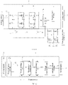
- FIG. 1 to FIG. 3 show module structures of an energy conversion apparatus 1 according to a first embodiment of this application. For ease of description, only a part that is related to this embodiment is shown, and detailed description is as follows:
- the energy conversion apparatus 1 includes an inductor 12, a bridge arm converter 13, a voltage transformation unit 14, and a first bidirectional H-bridge 15.
- the bridge arm converter 13 includes a first phase bridge arm 131, a second phase bridge arm 132, and a third phase bridge arm 133 connected in sequence.
- An end of an external charging port 2 is connected to an end of the inductor 12, and an other end of the external charging port 2 is connected to the bridge arm converter 13; and an other end of the inductor 12 is connected to the first phase bridge arm 131.
- the first phase bridge arm 131, the second phase bridge arm 132, and the third phase bridge arm 133 are connected in parallel, the second phase bridge arm 132 and the third phase bridge arm 133 are separately connected to an input end of the voltage transformation unit 14, an output end of the voltage transformation unit 14 is connected to an input end of the first bidirectional H-bridge 15, and an output end of the first bidirectional H-bridge 15 is connected to an external battery 3.
- the bridge arm converter 13 is further connected between the external battery 3 and an external motor 4.
- the energy conversion apparatus 1 works in a drive mode and a charging mode in a time-sharing manner.
- the external battery 3 provides a DC to the bridge arm converter 13
- the first phase bridge arm 131 in the bridge arm converter 13 converts the DC into a three-phase AC
- the external motor 4 outputs an AC
- the AC is converted by using the second phase bridge arm 132 and the third phase bridge arm 133 in the bridge arm converter 13, and a DC is outputted and is returned to the external battery 3.
- the external charging port 2 When the energy conversion apparatus 1 works in the charging mode, as shown in FIG. 3 , in the charging mode, the external charging port 2, the inductor 12, the bridge arm converter 13, the voltage transformation unit 14, and the first bidirectional H-bridge 15 form a charging circuit for charging the external battery 3.
- a power supply provided by the external charging port 2 for the charging circuit may be a DC power supply.
- the external charging port 2 When the external charging port 2 provides the DC power supply, as shown in FIG. 3 , the external charging port 2, the inductor 12, the bridge arm converter 13, the voltage transformation unit 14, the first bidirectional H-bridge 15, and the external battery 3 form a DC charging circuit.
- a DC outputted by the external charging port 2 is boosted through the inductor 12 and the first phase bridge arm 131 in the bridge arm converter 13, a DC is outputted, the DC outputted by the first phase bridge arm 131 is converted by using the second phase bridge arm 132 and the third phase bridge arm 133 in the bridge arm converter 13, an AC is outputted, the voltage transformation unit 14 converts a high-frequency AC and outputs another high-frequency AC, and the first bidirectional H-bridge 15 rectifies the high-frequency AC outputted by the voltage transformation unit 14 and outputs a DC for charging the external battery 3.
- the external charging port 2 the inductor 12, the first phase bridge arm 131, and the external battery 3 form a DC charging circuit.
- the DC outputted by the external charging port 2 is boosted through the inductor 12 and the first phase bridge arm 131 in the bridge arm converter 13, and a DC is outputted to charge the external battery 3.
- the inductor 12 in the foregoing charging mode, is configured to store and release electric energy.
- the bridge arm converter 13 includes at least three phase bridge arms connected in parallel, each phase bridge arm is connected to the external battery 3 and the external motor 4, and each phase bridge arm includes two power switches connected in series.
- the bridge arm converter 13 is configured to convert electric energy inputted by the external battery 3 and output a three-phase AC to drive the external motor 4; and in the foregoing charging mode, the bridge arm converter 13 is configured to convert electric energy in a charging loop and output a DC or a high-frequency AC, and a charging power is also increased, to charge the external battery 3.
- the bridge arm converter 13 in this embodiment may alternatively be another multi-phase bridge arm converter, for example, a six-phase bridge arm converter.
- the bridge arm converter 13 has six phase bridge arms, which are respectively a first phase bridge arm 131, a second phase bridge arm 132, a third phase bridge arm 133, a fourth phase bridge arm 134, a fifth phase bridge arm 135, and a sixth phase bridge arm 136 connected in parallel with each other, each phase bridge arm is connected to the external battery 3 and the external motor 4, and each phase bridge arm includes two power switches connected in series.
- each phase bridge arm includes two power switches connected in series.
- bridge arms connected to the voltage transformation unit are not limited to the second phase bridge arm 132 and the third phase bridge arm 133, or may be other bridge arms that can convert a DC outputted by the first phase bridge arm 131 into an AC.
- the other bridge arms may be the third phase bridge arm 133 and the fourth phase bridge arm 134, which are not specifically limited herein.
- the voltage transformation unit 14 in the foregoing charging mode, is configured to convert an AC inputted in the charging loop into another AC for output, to isolate circuits on two sides of the voltage transformation unit 14.
- the first bidirectional H-bridge 15 includes at least two bridge arms connected in parallel, and each bridge arm includes two power switches connected in series. In the foregoing charging mode, the first bidirectional H-bridge 15 is configured to rectify the AC in the charging loop and output a DC for charging the external battery 3.
- the DC power supply provides a DC to the energy conversion apparatus 1 through the external charging port 2, and the DC power supply may be a DC obtained by rectifying an external AC power supply, or may be a DC outputted by an external charging pile, which is not specifically limited herein.
- the energy conversion apparatus 1 may be not limited to working in the foregoing drive mode and charging mode, and various working modes of the energy conversion apparatus 1 are described subsequently in detail. Details are not described herein again.
- the energy conversion apparatus 1 including the inductor 12, the bridge arm converter 13, the voltage transformation unit 14, and the first bidirectional H-bridge 15, the energy conversion apparatus 1 works in the drive mode and the charging mode in a time-sharing manner.
- the external battery 3, the bridge arm converter 13, and the external motor 4 form the drive circuit for driving the external motor 4; and during charging, the external charging port 2, the inductor 12, the first phase bridge arm 131, and the external battery 3 form a charging circuit, or the external charging port 2, the inductor 12, the bridge arm converter 13, the voltage transformation unit 14, the first bidirectional H-bridge 15, and the external battery 3 form a charging circuit.
- the bridge arm converter 13 is reused, which not only simplifies a circuit structure, but also improves integration, thereby reducing a volume and reducing costs, to resolve existing problems that an overall control circuit including the battery charging circuit and the motor drive circuit has a complex structure, low integration, a large volume, and high costs.
- the external motor 4 includes a motor coil 41
- the first phase bridge arm 131 includes a first power switch Q1 and a second power switch Q2 connected in series
- the second phase bridge arm 132 includes a third power switch Q3 and a fourth power switch Q4 connected in series
- the third phase bridge arm 133 includes a fifth power switch Q5 and a sixth power switch Q6 connected in series.
- a first midpoint between the first power switch Q1 and the second power switch Q2 is connected to the inductor 12
- a second midpoint between the third power switch Q3 and the fourth power switch Q4 is connected to the voltage transformation unit 14
- a third midpoint between the fifth power switch Q5 and the sixth power switch Q6 is connected to the voltage transformation unit 14
- a first end of the first power switch Q1, a first end of the third power switch Q3, and a first end of the fifth power switch Q5 are together connected to form a first confluence end of the bridge arm converter 13
- a second end of the second power switch Q2, a second end of the fourth power switch Q4, and a second end of the sixth power switch Q6 are together connected to form a second confluence end of the bridge arm converter 13
- the second confluence end is connected to an external charging port 2
- the first confluence end is connected to an end of an external battery 3
- the second confluence end is connected to an other end of the external battery 3
- the first midpoint is connected
- the first midpoint between the first power switch Q1 and the second power switch Q2 is a point on a connecting line between the first power switch Q1 and the second power switch Q2, and the inductor 12 is connected to both the first power switch Q1 and the second power switch Q2 by the point.
- positions of the second midpoint and the third midpoint may be inferred. Details are not described herein again.
- a plurality of power switches in the bridge arm converter 13 may be implemented by using a device that is connected in parallel to a diode and may perform a switch action, for example, a switch device such as a power triode, a metal-oxide-semiconductor field-effect transistor (MOSFET), and an insulated gate bipolar transistor (IGBT).
- a switch device such as a power triode, a metal-oxide-semiconductor field-effect transistor (MOSFET), and an insulated gate bipolar transistor (IGBT).
- MOSFET metal-oxide-semiconductor field-effect transistor
- IGBT insulated gate bipolar transistor
- a power switch in the first phase bridge arm 131, a power switch in the second phase bridge arm 132, and a power switch in the third phase bridge arm 133 receive control signals having a difference of a preset phase.
- the preset phase is preferably an angle of 120 degrees, but the preferable angle does not limit the preset phase.
- the inductor 12 in the energy conversion apparatus 1 when the inductor 12 in the energy conversion apparatus 1 receives the DC, the inductor 12 may store and release the electric energy by switching between an on state and an off state of the first power switch Q1 and the second power switch Q2, to implement power factor correction (PFC).
- PFC power factor correction
- three phase bridge arms of the bridge arm converter 13 are controlled in a three-phase interleaved control working manner, so that when the energy conversion apparatus 1 performs charging, a DC-side ripple is reduced and a charging power is increased.
- the first phase bridge arm 131 may cooperate with the inductor 12 to complete the PFC, boosting is performed by using the first power switch Q1, and a DC voltage is outputted.
- the second phase bridge arm 132 and the third phase bridge arm 133 may convert the DC into a high-frequency AC.
- a drive mode by controlling the three phase bridge arms in the bridge arm converter 13, electric energy inputted by the external battery 3 is converted, and a voltage and a current of the motor coil 41 are adjusted, to drive the external motor 4.
- the energy conversion apparatus 1 further includes a first capacitor C1, and the first capacitor C1 is connected between the first confluence end and the second confluence end.
- the first capacitor C1 filters a voltage outputted by the bridge arm converter 13, and may store energy according to the voltage outputted by the bridge arm converter 13, to complete a DC charging process of the external battery 3.
- the first capacitor C1 filters the voltage inputted to the bridge arm converter 13.
- the first capacitor C1 can store energy according to the voltage outputted by the bridge arm converter 13 in addition to filtering the voltage outputted by the bridge arm converter 13, to complete the charging of the external battery 3, thereby ensuring a normal charging function of the energy conversion apparatus 1, and also ensuring that other clutter does not interfere with the charging process.
- a voltage inputted to the bridge arm converter 13 may be further filtered.
- the voltage transformation unit 14 in the energy conversion apparatus 1 includes a primary coil T0 and a first secondary coil T1.
- an end of the primary coil T0 is connected to a second midpoint
- an other end of the primary coil T0 is connected to a third midpoint
- the first secondary coil T1 is connected to a first bidirectional H-bridge 15, so that an external charging port 2, an inductor 12, abridge arm converter 13, the primary coil T0, the first secondary coil T1, the first bidirectional H-bridge 15, and an external battery 3 form a DC charging loop.
- the energy conversion apparatus 1 further includes a first inductor L1 and a second capacitor C2.
- the first inductor L1 is disposed between a side of the primary coil T0 and the second midpoint
- the second capacitor C2 is disposed between an other side of the primary coil T0 and the third midpoint.
- the external charging port 2 the inductor 12, the first phase bridge arm 131, the second phase bridge arm 132, the third phase bridge arm 133, the first inductor LI, the second capacitor C2, the primary coil T0, the first secondary coil T1, the first bidirectional H-bridge 15, and the external battery 3 form a DC charging circuit, and the first inductor L1 and the second capacitor C2 generate a resonance effect in the DC charging circuit, to assist power switches in the second phase bridge arm 132 and the third phase bridge arm 133 in implementing soft switching.
- the energy conversion apparatus 1 further includes a second inductor L2 and a third capacitor C3.
- the second inductor L2 is disposed between a side of the first secondary coil T1 and the fourth midpoint, and the third capacitor C3 is disposed between an other side of the first secondary coil T1 and the fifth midpoint.
- the external charging port 2 the inductor 12, the first phase bridge arm 131, the second phase bridge arm 132, the third phase bridge arm 133, the primary coil T0, the first secondary coil T1, the second inductor L2, the third capacitor C3, a seventh power switch Q7, an eighth power switch Q8, a ninth power switch Q9, a tenth power switch Q10, and the external battery 3 form a DC charging circuit
- the second inductor L2 and the third capacitor C3 generate a resonance effect in the DC charging circuit, to assist power switches in a seventh phase bridge arm 151 and an eighth phase bridge arm 152 in implementing soft switching.
- the first bidirectional H-bridge 15 in the energy conversion apparatus 1 includes a seventh phase bridge arm 151 and an eighth phase bridge arm 152.
- the seventh phase bridge arm 151 includes a seventh power switch Q7 and an eighth power switch Q8 connected in series
- the eighth phase bridge arm 152 includes a ninth power switch Q9 and a tenth power switch Q10 connected in series.
- a fourth midpoint between the seventh power switch Q7 and the eighth power switch Q8 is connected to an end of the first secondary coil T1
- a fifth midpoint between the ninth power switch Q9 and the tenth power switch Q10 is connected to an other end of the first secondary coil T1
- a first end of the seventh power switch Q7 and a first end of the ninth power switch Q9 are together connected to form a third confluence end of the first bidirectional H-bridge 15
- a second end of the eighth power switch Q8 and a second end of the tenth power switch Q10 are together connected to form a fourth confluence end of the first bidirectional H-bridge 15
- the third confluence end is connected to an end of the external battery 3
- the fourth confluence end is connected to an other end of the external battery 3.
- the external charging port 2, the inductor 12, the first phase bridge arm 131, the second phase bridge arm 132, the third phase bridge arm 133, the primary coil T0, the first secondary coil T1, the seventh power switch Q7, the eighth power switch Q8, the ninth power switch Q9, the tenth power switch Q10, and the external battery 3 form a DC charging circuit, where the seventh power switch Q7, the eighth power switch Q8, the ninth power switch Q9, and the tenth power switch Q10 form a full-bridge rectification circuit.
- the full-bridge rectification circuit a high-frequency AC outputted by the first secondary coil T1 is rectified into a DC, and a DC voltage with high-frequency energy is outputted, to charge the external battery 3.
- a plurality of power switches in the first bidirectional H-bridge 15 may be implemented by using a device that is connected in parallel to a diode and may perform a switch action, for example, a switch device such as a power triode, an MOSFET, and an IGBT.
- the energy conversion apparatus 1 further includes a fourth capacitor C4.
- the external charging port 2 the inductor 12, the first phase bridge arm 131, the second phase bridge arm 132, the third phase bridge arm 133, the primary coil T0, the first secondary coil T1, the seventh power switch Q7, the eighth power switch Q8, the ninth power switch Q9, the tenth power switch Q10, the fourth capacitor C4, and the external battery 3 form a DC charging circuit, and a voltage outputted by the first bidirectional H-bridge 15 is filtered by using the fourth capacitor C4, to charge the external battery 3.
- the inputted high-frequency AC may be converted into another high-frequency AC for output in a formed DC charging loop, and circuits on two sides of the voltage transformation unit 14 are isolated, thereby avoiding electrostatic interference between the circuits on the two sides.
- the second phase bridge arm 132 and the third phase bridge arm 133 are reused, and the DC is converted into the AC, thereby simplifying a circuit structure, reducing a volume, and reducing costs.
- the voltage transformation unit 14 in the energy conversion apparatus 1 further includes a second secondary coil T2.
- the second secondary coil T2 is connected to a storage battery or an in-vehicle discharging port by a second bidirectional H-bridge 16.
- the external charging port 2 When the storage battery is charged, the external charging port 2, the inductor 12, the bridge arm converter 13, the voltage transformation unit 14, and the second bidirectional H-bridge 16 form a charging circuit for the storage battery; when the external charging port 2 is connected to a charging device and the in-vehicle discharging port is connected to an electricity consumption device, and the external charging port 2, the inductor 12, the bridge arm converter 13, the voltage transformation unit 14, and the second bidirectional H-bridge 16 form a charging circuit for the electricity consumption device; and when the external charging port 2 is not connected to the charging device and the in-vehicle discharging port is connected to the electricity consumption device, the external battery 3, the first bidirectional H-bridge 15, the voltage transformation unit 14, and the second bidirectional H-bridge 16 form a discharging circuit for the electricity consumption device.
- a storage battery charging loop or an in-vehicle discharging port loop may be formed by the external charging port 2, the inductor 12, the bridge arm converter 13, the primary coil T0, the second secondary coil T2, the second bidirectional H-bridge 16, and the storage battery or the in-vehicle discharging port, so that the DC charging loop, and the storage battery charging loop or the in-vehicle discharging port loop do not interfere with each other during working, thereby improving the circuit reliability, and the external battery 3 may discharge to the electricity consumption device connected to the in-vehicle discharging port, thereby increasing functions of an overall control circuit.
- the second bidirectional H-bridge 16 in the energy conversion apparatus 1 includes a ninth phase bridge arm 161 and a tenth phase bridge arm 162.
- the ninth phase bridge arm 161 includes a thirteenth power switch Q13 and a fourteenth power switch Q14 connected in series
- the tenth phase bridge arm 162 includes a fifteenth power switch Q15 and a sixteenth power switch Q16 connected in series.
- a seventh midpoint between the thirteenth power switch Q13 and the fourteenth power switch Q14 is connected to an end of the second secondary coil T2
- an eighth midpoint between the fifteenth power switch Q15 and the sixteenth power switch Q16 is connected to an other end of the second secondary coil T2
- a first end of the thirteenth power switch Q13 and a first end of the fourteenth power switch Q14 are together connected to form a fifth confluence end of the second bidirectional H-bridge
- a second end of the fourteenth power switch Q14 and a second end of the sixteenth power switch Q16 are together connected to form a sixth confluence end of the second bidirectional H-bridge 16
- the fifth confluence end is connected to an end of the storage battery or the in-vehicle discharging port
- the sixth confluence end is connected to an other end of the storage battery or the in-vehicle discharging port.
- a plurality of power switches in the second bidirectional H-bridge 16 may be implemented by using a device that is connected in parallel to a diode and may perform a switch action, for example, a switch device such as a power triode, an MOSFET, and an IGBT.
- the energy conversion apparatus 1 when the external charging port 2 is an AC charging port 21, the energy conversion apparatus 1 further includes a first rectification module 17a.
- the first rectification module 17a is separately connected to the AC charging port 21, the inductor 12, and the bridge arm converter 13.
- the first rectification module 17a may include a rectification bridge, a first input end and a second input end of the rectification bridge are separately connected to the AC charging port 21, an output end of the rectification bridge is connected to the inductor 12, and an other output end of the rectification bridge is connected to the bridge arm converter 13.
- the AC charging port 21, the first rectification module 17a, the inductor 12, the bridge arm converter 13, the voltage transformation unit 14, the first bidirectional H-bridge 15, and the external battery 3 form an AC charging circuit
- the AC charging port 21, the first rectification module 17a, the inductor 12, the first phase bridge arm 131, and the external battery 3 form an AC charging circuit.
- the first rectification module 17a rectifies an AC inputted by the AC charging port 21 into a DC for charging the external battery 3.
- the external battery 3, the first bidirectional H-bridge 15, the voltage transformation unit 14, the bridge arm converter 13, the inductor 12, the first rectification module 17a, and the AC charging port 21 form an AC discharging circuit, or the external battery 3, the first phase bridge arm 131, the inductor 12, the first rectification module 17a, and the AC charging port 21 form an AC discharging circuit.
- the foregoing AC discharging circuit by switching a power switch in the first rectification module 17a, the DC is converted into the AC, for the AC charging port 21 to discharge.
- the external charging port 2 is an AC charging port 21 and a DC charging port 22, and the energy conversion apparatus 1 further includes a second rectification module 17b.
- the second rectification module 17b is separately connected to the AC charging port 21, the inductor 12, and the bridge arm converter 13.
- the AC charging port 21, the second rectification module 17b, the inductor 12, the bridge arm converter 13, the voltage transformation unit 14, the first bidirectional H-bridge 15, and the external battery 3 form an AC charging circuit
- the AC charging port 21, the second rectification module 17b, the inductor 12, the first phase bridge arm 131, and the external battery 3 form an AC charging circuit
- the second rectification module 17b rectifies an AC inputted by the AC charging port 21 into a DC for charging the external battery 3.
- the external battery 3, the first bidirectional H-bridge 15, the voltage transformation unit 14, the bridge arm converter 13, the inductor 12, the second rectification module 17b, and the AC charging port 21 form an AC discharging circuit, or the external battery 3, the first phase bridge arm 131, the inductor 12, the second rectification module 17b, and the AC charging port 21 form an AC discharging circuit.
- the DC is converted into the AC, for the AC charging port 21 to discharge.
- the DC charging port 22, the inductor 12, the bridge arm converter 13, the voltage transformation unit 14, the first bidirectional H-bridge 15, and the external battery 3 form a DC charging circuit, or the DC charging port 22, the inductor 12, the first phase bridge arm 131, and the external battery 3 form a DC charging circuit.
- the external battery 3, the first bidirectional H-bridge 15, the voltage transformation unit 14, the bridge arm converter 13, the inductor 12, and the DC charging port 22 form a DC discharging circuit, or the external battery 3, the first phase bridge arm 131, the inductor 12, and the DC charging port 22 form a DC discharging circuit.
- the energy conversion apparatus 1 when the external charging port 2 is an AC charging port 21 and a DC charging port 22, the energy conversion apparatus 1 further includes a bidirectional bridge arm 18.
- the bidirectional bridge arm 18 is separately connected to the AC charging port 21 and the bridge arm converter 13.
- the AC charging port 21, the inductor 12, the bridge arm converter 13, the bidirectional bridge arm 18, the voltage transformation unit 14, the first bidirectional H-bridge 15, and the external battery 3 form an AC charging circuit.
- the bidirectional bridge arm 18 cooperates with the first phase bridge arm 131 to form a bidirectional H-bridge, which converts the AC into the DC, and the DC is then converted into the AC by using the second phase bridge arm 132 and the third phase bridge arm 133, so that the voltage transformation unit 14 receives a high-frequency AC, and then rectifies the high-frequency AC into the DC through the first bidirectional H-bridge, to charge the external battery 3.
- the external battery 3, the first bidirectional H-bridge, the voltage transformation unit 14, the bidirectional bridge arm 18, the bridge arm converter 13, the inductor 12, and the AC charging port 21 form an AC discharging circuit.
- the bidirectional bridge arm 18 cooperates with the first phase bridge arm 131 to form a bidirectional H-bridge, which converts the DC into the AC, for the AC charging port 21 to discharge.
- the DC charging port 22, the inductor 12, the bridge arm converter 13, the voltage transformation unit 14, the first bidirectional H-bridge 15, and the external battery 3 form a DC charging circuit; or the DC charging port 22, the inductor 12, the first phase bridge arm 131, and the external battery 3 form a DC charging circuit.
- the external battery 3, the first bidirectional H-bridge 15, the voltage transformation unit 14, the bridge arm converter 13, the inductor 12, and the DC charging port 22 form a DC discharging circuit, or the external battery 3, the first phase bridge arm 131, the inductor 12, and the DC charging port 22 form a DC discharging circuit.
- the bidirectional bridge arm 18 in the energy conversion apparatus 1 includes an eleventh power switch Q11 and a twelfth power switch Q12 connected in series.
- a sixth midpoint between the eleventh power switch Q11 and the twelfth power switch Q12 is connected to the AC charging port 21, a first end of the eleventh power switch Q11 is connected to a first confluence end of the bridge arm converter 13, and a second end of the twelfth power switch Q12 is connected to a second confluence end of the bridge arm converter 13.
- the AC charging port 21, the inductor 12, the bridge arm converter 13, the eleventh power switch Q11, the twelfth power switch Q12, the voltage transformation unit 14, the first bidirectional H-bridge 15, and the external battery 3 form an AC charging circuit.
- the eleventh power switch Q11 and the twelfth power switch Q12 may cooperate with the first power switch Q1 and the second power switch Q2 in the first phase bridge arm 131 to form a bidirectional H-bridge, which converts the AC into the DC.
- household power strips are generally used during AC charging, and a power of a common AC power supply is generally 7 kilowatts (kW).
- kW kilowatts
- professional charging piles whose power is generally 60 kW to 150 kW are generally used during DC charging, and fast DC charging piles whose power is greater than 100 kW are a development trend.
- a power is generally about 100 kW during motor drive. Therefore, it can be learned from the foregoing description that power levels of a vehicle in the three cases of the motor drive, the DC charging, and the AC charging have a very large difference, but the power difference is very important for power switch selection.
- types of the power switches in the bridge arm converter 13 and types of the power switches in the bidirectional bridge arm 18 may be the same, or may be different. Specifically, a high-power power switch is more expensive than a low-power power switch. Therefore, based on consideration of different powers required when the energy conversion apparatus 1 works in the motor drive mode, the DC charging mode, and the AC charging mode, the types of the power switches in the bridge arm converter 13 and the types of the power switches in the bidirectional bridge arm 18 may be different.
- power switches of different power levels for example, an MOSFET power switch of a high-current level and an MOSFET power switch of a low-current level
- different types of switches for example, a high-power IGBT power switch and a low-power MOSFET power switch
- the bridge arm converter 13 in this embodiment is implemented by using the high-power IGBT power switch, or is implemented by using the MOSFET power switch of the high-current level.
- the bidirectional bridge arm 18 mainly works in the AC charging mode, the bidirectional bridge arm 18 may be implemented by using the low-power MOSFET, thereby reducing circuit costs while ensuring the effective working of the energy conversion apparatus 1.
- the bidirectional bridge arm 18 requires a relatively high switching frequency (for example, 60 kHz) during AC charging, it is necessary to use a MOSFET power switch that may achieve relatively high efficiency during high-frequency working or a silicon carbide MOSFET power switch.
- the bridge arm converter 13 has three phase bridge arms, and has a working manner of three-phase interleaved control, the power switches of the bridge arm converter 13 require a relatively low frequency. Therefore, the types of the power switches in the bridge arm converter 13 and the types of the power switches in the bidirectional bridge arm 18 may be different.
- the energy conversion apparatus 1 further includes a switch module 19.
- the switch module 19 includes a first switch unit 191, a second switch unit 192, and a third switch unit 193, where the first switch unit 191 is disposed between the AC charging port 21 and the first rectification module 17a, the second switch unit 192 is disposed between the DC charging port 22 and the bridge arm converter 13, and the third switch unit 193 is disposed between the motor coil 41 and the bridge arm converter 13.
- the first switch unit 191 includes a switch K1 and a switch K2, where an end of the switch K1 is connected to the AC charging port 21, an other end of the switch K1 is connected to the first rectification module 17a, an end of the switch K2 is connected to the AC charging port 21, and an other end of the switch K2 is connected to the first rectification module 17a.
- the second switch unit 192 includes a switch K3 and a switch K4, where an end of the switch K3 is connected to the DC charging port 22, an other end of the switch K3 is connected to the inductor 12, an end of the switch K4 is connected to the DC charging port 22, and an other end of the switch K4 is connected to the first phase bridge arm 131.
- the third switch unit 193 includes a switch K5, a switch K6, and a switch K7, where an end of the switch K5 is connected to the first midpoint, an other end of the switch K5 is connected to the first phase coil, an end of the switch K6 is connected to the second midpoint, an other end of the switch K6 is connected to the second phase coil, an end of the switch K7 is connected to the third midpoint, and an other end of the switch K7 is connected to the third phase coil.
- the first rectification module 17a in the AC charging circuit formed by the AC charging port 21, the first rectification module 17a, the inductor 12, the bridge arm converter 13, the voltage transformation unit 14, the first bidirectional H-bridge 15, and the external battery 3, may alternatively use the same circuit structure as that of the second rectification module 17b, or may use another circuit having a rectification function.
- the switch K1 and the switch K2 in the first switch unit 191 are turned on, the switch K3 and the switch K4 in the second switch unit 192 are turned off, and the switch K5, the switch K6, and the switch K7 in the third switch unit 193 are turned off, the AC charging port 21, the first rectification module 17a, the inductor 12, the bridge arm converter 13, the voltage transformation unit 14, the first bidirectional H-bridge 15, and the external battery 3 form an AC charging circuit.
- the switch K1 and the switch K2 in the first switch unit 191 are turned off, the switch K3 and the switch K4 in the second switch unit 192 are turned on, and the switch K5, the switch K6, and the switch K7 in the third switch unit 193 are turned off, the DC charging port 22, the inductor 12, the bridge arm converter 13, the voltage transformation unit 14, the first bidirectional H -bridge 15, and the external battery 3 form a DC charging circuit, or the DC charging port 22, the inductor 12, the first phase bridge arm 131, and the external battery 3 form a DC charging circuit.
- a contactor switch is disposed between the external battery 3 and the bridge arm converter 13.
- the contactor switch When the contactor switch is in a closed state, the external battery 3, the bridge arm converter, and the external motor 4 form a motor drive circuit.
- the energy conversion apparatus 1 further includes a resistor R1
- the switch module 19 in the energy conversion apparatus 1 further includes a fourth switch unit 194.
- the fourth switch unit 194 includes a switch K8, a switch K9, and a switch K10.
- An end of the switch K8 and an end of the switch K9 are connected to the first bidirectional H-bridge 15, an other end of the switch K8 is connected to an end of the resistor R1, an other end of the switch K9 and an other end of the resistor R1 are connected to an end of the external battery 3, an end of the switch K10 is connected to the first bidirectional H-bridge 15, and an other end of the switch K10 is connected to an other end of the external battery 3.
- an end of the switch K8 and an end of the switch K9 are connected to the third confluence end of the first bidirectional H-bridge 15, and an end of the switch K10 is connected to the fourth confluence end of the first bidirectional H-bridge 15.
- the switch K8 and the resistor R1 in the energy conversion apparatus 1 form a pre-charging module.
- the switch K1 and the switch K2 in the first switch unit 191 are turned on, the switch K3 and the switch K4 in the second switch unit 192 are turned off, and the switch K5, the switch K6, and the switch K7 in the third switch unit 193 are turned off; or the switch K1 and the switch K2 in the first switch unit 191 are turned off, the switch K3 and the switch K4 in the second switch unit 192 are turned on, and the switch K5, the switch K6, and the switch K7 in the third switch unit 193 are turned off, the switch K8 is turned on, and after pre-charging is performed through R1, the switch K9 and the switch K10 are turned on.
- the pre-charging is performed through R1, to prevent the switch K9 and the switch K10 from failing, thereby reducing a failure rate of the energy conversion apparatus 1.
- the switch K1 and the switch K2 are turned on, the switch K3, the switch K4, the switch K5, the switch K6, and the switch K7 are turned off, the contactor switch between the external battery 3 and the bridge arm converter 13 is turned off, pre-charging is completed through the switch K8 and the resistor R1, and the switch K9 and the switch K10 are turned on.
- the AC charging port 21 inputs an AC
- the first rectification module 17a rectifies the AC and outputs a DC
- PFC is completed by using the inductor 12
- DC-AC conversion is implemented by using the third power switch Q3, the fourth power switch Q4, the fifth power switch Q5 and the sixth power switch Q6.
- the third power switch Q3 and the fourth power switch Q4 output high-frequency AC positive waves
- the fifth power switch Q5 and the sixth power switch Q6 output high-frequency AC negative waves
- the voltage transformation unit 14 and the first bidirectional H-bridge 15 perform voltage transformation and rectification processing on the high-frequency AC outputted by the bridge arm converter 13, to implement AC-DC conversion.
- a DC voltage is outputted
- the fourth capacitor C4 filters the DC voltage to charge the external battery 3.
- the switch K1 and the switch K2 are turned on, the switch K3, the switch K4, the switch K5, the switch K6, and the switch K7 are turned off, the contactor switch between the external battery 3 and the bridge arm converter 13 is turned on, pre-charging is completed through the switch K8 and the resistor R1, and the switch K9 and the switch K10 are turned on.
- the AC charging port 21 inputs an AC
- the first rectification module 17a rectifies the AC and outputs a DC
- PFC is completed by using the inductor 12, the first power switch Q1, and the second power switch Q2, and the DC is rectified by using the first power switch Q1, and is filtered by using the first capacitor C1 to output a DC voltage to charge the external battery 3.
- the AC received by the AC charging port 21 performs AC charging to the external battery 3 after passing through the first rectification module 17a, the inductor 12, the bridge arm converter 13, the first capacitor C1, the voltage transformation unit 14, the first bidirectional H-bridge 15, and the fourth capacitor C4, and AC charging manners are not limited to one manner. That is, the AC charging manners of the energy conversion apparatus 1 are multi-solution redundant, and the working voltage may be self-adjusted, so that the AC charging function of the energy conversion apparatus 1 can be effectively ensured while improving the charging efficiency.
- the switch K3 and the switch K4 are turned on, the switch K1, the switch K2, the switch K5, the switch K6, and the switch K7 are turned off, the contactor switch between the external battery 3 and the bridge arm converter 13 is turned off, the contactor switch between external battery 3 and bridge arm converter 13 is turned off, pre-charging is completed by using the switch K8 and the resistor R1, and the switch K9 and the switch K10 are turned on.
- the DC charging port 22 outputs the DC
- the PFC is completed by using the inductor 12
- DC-AC conversion is implemented by using the third power switch Q3, the fourth power switch Q4, the fifth power switch Q5, and the sixth power switch Q6.
- the third power switch Q3 and the fourth power switch Q4 output high-frequency AC positive waves
- the fifth power switch Q5 and the sixth power switch Q6 output high-frequency AC negative waves
- the voltage transformation unit 14 and the first bidirectional H-bridge 15 perform voltage transformation and rectification processing on the high-frequency AC outputted by the bridge arm converter 13, to implement AC-DC conversion.
- a DC voltage is outputted
- the fourth capacitor C4 filters the DC voltage to charge the external battery 3.
- the switch K3 and the switch K4 are turned on, the switch K1, the switch K2, the switch K5, the switch K6, and the switch K7 are turned off, the contactor switch between the external battery 3 and the bridge arm converter 13 is turned on, pre-charging is completed by using the switch K8 and the resistor R1, and the switch K9 and the switch K10 are turned on.
- the DC charging port 22 outputs a DC
- the PFC is completed by using the inductor 12, the first power switch Q1, and the second power switch Q2, and the DC is rectified by using the first power switch Q1 and is filtered by using the first capacitor C1 to output a DC voltage to charge the external battery 3.
- the switch K5, the switch K6, and the switch K7 are turned on, the switch K1, the switch K2, the switch K3, the switch K4, the switch K8, the switch K9, and the switch K10 are turned off, and the contactor switch between the external battery 3 and the bridge arm converter 13 is turned on.
- the external battery 3 outputs a high-voltage DC.
- the high-voltage DC outputs a three-phase AC to a three-phase winding of the motor coil 41 through a three-phase motor drive bridge of the bridge arm converter 12 to drive the external motor 4.
- the voltage transformation unit 14 of the energy conversion apparatus 1 further includes a second secondary coil T2.
- the external charging port 2 When the energy conversion apparatus 1 performs DC charging or AC charging, the external charging port 2, the inductor 12, the bridge arm converter 13, the voltage transformation unit 14, and the second bidirectional H-bridge 16 form a charging circuit for charging the storage battery or an electricity consumption device connected to the in-vehicle discharging port.
- the energy conversion apparatus 1 may further work in a discharging mode.
- the following describes the working principle of this application by using the energy conversion apparatus 1 shown in FIG. 20 as an example.
- the switch K1, the switch K2, the switch K9, and the switch K10 are turned on, and the switch K3, the switch K4, the switch K5, the switch K6, and the switch K7 are turned off, so that the high-voltage DC outputted by the external battery 3 discharges to the outside through the AC charging port 22 under the action of the first bidirectional H-bridge 15, the voltage transformation unit 14, the bridge arm converter 13, and the inductor 12.
- the switch K3, the switch K4, the switch K9, and the switch K10 are turned on, and the switch K1, the switch K2, the switch K5, the switch K6, and the switch K7 are turned off, so that the high-voltage DC outputted by the external battery 3 discharges to the outside through the DC charging port 22 under the action of the first bidirectional H-bridge 15, the voltage transformation unit 14, the bridge arm converter 13, and the inductor 12.
- the switch K1 and the switch K2 are turned on, the switch K3, the switch K4, the switch K5, the switch K6, the switch K7, the switch K8, the switch K9, and the switch K10 are turned off, and the AC charging port 21, the first rectification module 17a, the inductor 12, the bridge arm converter 13, the primary coil T0, the second secondary coil T2, the second bidirectional H-bridge 16, and the storage battery or the in-vehicle discharging port form an AC discharging circuit;
- the principle of the AC discharging working mode of the energy conversion apparatus 1 is opposite to the principle of the AC charging working mode of the energy conversion apparatus. Therefore, for a specific working principle of the AC discharging working mode of the energy conversion apparatus 1, reference may be made to a specific working process of the AC charging mode of the energy conversion apparatus, and details are not described herein again.
- the drive of the external motor 4 can be implemented by using the bridge arm converter 13; a voltage outputted by the first phase bridge arm 131 is increased while PFC is implemented by using the cooperation between the first phase bridge arm 131 in the bridge arm converter 13 and the inductor 12; and the DC may be converted into the AC by using the second phase bridge arm 132 and the third phase bridge arm 133 in the bridge arm converter 13, and AC charging and discharging and DC charging and discharging of the vehicle battery may be further performed by using the energy conversion apparatus 1.
- the bridge arm converter 13 is reused, thereby simplifying the circuit structure, improving the circuit integration, reducing the circuit costs, reducing the circuit volume, and achieving a simple circuit structure.
- the energy conversion apparatus 1 provided in this application may work in both the AC charging mode and the AC discharging mode, application scenarios of charging are increased, and an application scope is expanded.
- the power system 5 includes an energy conversion apparatus 1 and a control module 54, where the energy conversion apparatus 1 includes an in-vehicle charging module 51, a motor control module 52, and a bidirectional DC/DC module 53.
- the in-vehicle charging module 51 includes an inductor 12; and the inductor 12 is connected to an external charging port 2.
- the motor control module 52 includes a bridge arm converter 13; and the bridge arm converter 13 is separately connected to the external charging port 2, the inductor 12, an external motor 4, and an external battery 3.
- the bidirectional DC/DC module 53 includes a voltage transformation unit 14 and a first bidirectional H-bridge 15. An end of the voltage transformation unit 14 is connected to the bridge arm converter 13, an other end of the voltage transformation unit 14 is connected to an end of the first bidirectional H-bridge 15, and an other end of the first bidirectional H-bridge 15 is connected to the external battery 3.
- the control module 54 is separately connected to the bridge arm converter 13 and the first bidirectional H-bridge 15.
- the control module is configured to control a drive circuit formed by the external battery 3, the bridge arm converter 13 and the external motor 4 and is configured to control a charging circuit formed by the external charging port 2, the inductor 12, the bridge arm converter 13, the voltage transformation unit 14, the first bidirectional H-bridge 15, and the external battery 3.
- the energy conversion apparatus 1 in the system 5 further includes a switch module 19, and the control module 54 is configured to control the switch module 19, to implement switching between a charging mode and a drive mode.
- the control module 54 controls the switch units in the switch module 19 and power switches in the energy conversion apparatus 1 to switch a working mode of the energy conversion apparatus 1.
- the external battery 3 drives, by using the bridge arm converter 13, the external motor 4 to work.
- the external battery 3 provides a DC to the bridge arm converter 13, the first phase bridge arm 131 in the bridge arm converter 13 converts the DC into a three-phase AC and inputs the three-phase AC to the external motor 4 to drive the external motor 4 to run, the external motor 4 outputs an AC, the AC is converted by using the second phase bridge arm 132 and the third phase bridge arm 133 in the bridge arm converter 13, and a DC is outputted, and is returned to the external battery 3.
- the energy conversion apparatus 1 works in the charging mode, specifically, in the charging mode, the external charging port 2, the inductor 12, the bridge arm converter 13, the voltage transformation unit 14, and the first bidirectional H-bridge 15 form a charging circuit for charging the external battery 3.
- a power supply provided by the external charging port 2 is a DC power supply.
- a power supply provided by the external charging port 2 is a DC power supply
- the external charging port 2 the inductor 12, the bridge arm converter 13, the voltage transformation unit 14, the first bidirectional H-bridge 15, and the external battery 3 form a DC charging circuit.
- a DC outputted by the external charging port 2 is boosted through the inductor 12 and the first phase bridge arm 131 in the bridge arm converter 13, a DC is outputted, the DC outputted by the first phase bridge arm 131 is converted by using the second phase bridge arm 132 and the third phase bridge arm 133 in the bridge arm converter 13, an AC is outputted, the voltage transformation unit 14 converts a high-frequency AC and outputs another high-frequency AC, and the first bidirectional H-bridge 15 rectifies the high-frequency AC outputted by the voltage transformation unit 14 and outputs a DC for charging the external battery 3.
- the external charging port 2 the inductor 12, the first phase bridge arm 131, and the external battery 3 form a DC charging circuit.
- the DC outputted by the external charging port 2 is boosted through the inductor 12 and the first phase bridge arm 131 in the bridge arm converter 13, and a DC is outputted to charge the external battery 3.
- the external battery 3, the first bidirectional H-bridge 15, the voltage transformation unit 14, the bridge arm converter 13, the inductor 12, and the DC charging port 22 form a DC discharging circuit, or the external battery 3, the first phase bridge arm 131, the inductor 12, and the DC charging port 22 form a DC discharging circuit.
- the principle of the DC discharging working mode is opposite to the principle of the DC charging working mode.
- a specific working principle of the DC discharging working mode reference may be made to a specific working process of the DC charging mode, and details are not described herein again.
- the DC power supply or the AC power supply provides a DC or an AC to the power system 5 through the external charging port 2, and the DC power supply may be a DC obtained by rectifying an external AC power supply, or may be a DC outputted by an external charging pile, which is not specifically limited herein.
- the power system 5 may work in the drive mode and the DC charging mode in a time-sharing manner, and motor drive and battery charging of a vehicle may be performed by using the same circuit structure.
- the circuit integration is high, and the circuit structure is simple, thereby reducing circuit costs, reducing a circuit volume, and resolving existing problems that an overall circuit of the motor drive and charging system has a complex structure, low integration, a large volume, and high costs.
- the energy conversion apparatus 1 in the power system 5 further includes a first rectification module 17a, and in this case, the external charging port 2 is an AC charging port 21.
- the first rectification module 17a is separately connected to the AC charging port 21, the inductor 12, and the bridge arm converter 13.
- the control module 54 controls an on state and an off state of each switch in the switch module to implement switching between the AC charging mode and the drive mode.
- the control module 54 is configured to control an AC charging circuit formed by the AC charging port 21, the first rectification module 17a, the inductor 12, the bridge arm converter 13, the voltage transformation unit 14, the first bidirectional H-bridge 15, and the external battery 3, or an AC charging circuit formed by the AC charging port 21, the first rectification module 17a, the inductor 12, the first phase bridge arm 131, and the external battery 3.
- the working mode is switched to the drive mode by using the control module 54, the external battery 3, the bridge arm converter 13, and the external motor 4 form a drive circuit.
- the external battery 3, the first bidirectional H-bridge 15, the voltage transformation unit 14, the bridge arm converter 13, the inductor 12, the first rectification module 17a, and the AC charging port 21 form an AC discharging circuit
- the external battery 3 the first phase bridge arm 131, the inductor 12, the first rectification module 17a, and the AC charging port 21 form an AC discharging circuit.
- the DC is converted into the AC, for the AC charging port 21 to discharge.
- the first rectification module 17a rectifies the AC outputted by the AC charging port 21 into the DC, to charge the external battery 3, or the first rectification module 17a converts the DC into the AC, for the AC charging port 21 to discharge.
- the energy conversion apparatus 1 in the power system 5 further includes a second rectification module, and in this case, the external charging port 2 is the AC charging port 21 and the DC charging port 22.
- the second rectification module is separately connected to the AC charging port 21, the inductor 12, and the bridge arm converter 13, and the DC charging port 22 is separately connected to the inductor 12 and the bridge arm converter 13.
- the control module 54 controls an on state and an off state of each switch in the switch module to implement switching among the AC charging mode, the DC charging mode, and the drive mode.
- the AC charging port 21, the second rectification module 17b, the inductor 12, the bridge arm converter 13, the voltage transformation unit 14, the first bidirectional H-bridge 15, and the external battery 3 form an AC charging circuit
- the AC charging port 21, the second rectification module 17b, the inductor 12, the first phase bridge arm 131, and the external battery 3 form an AC charging circuit.
- the external battery 3, the first bidirectional H -bridge 15, the voltage transformation unit 14, the bridge arm converter 13, the inductor 12, the second rectification module 17b, and the AC charging port 21 form an AC discharging circuit
- the external battery 3 the first phase bridge arm 131, the inductor 12, the second rectification module 17b, and the AC charging port 21 form an AC discharging circuit.
- the DC is converted into the AC, for the AC charging port 21 to discharge.
- the DC charging port 22, the inductor 12, the bridge arm converter 13, the voltage transformation unit 14, the first bidirectional H-bridge 15, and the external battery 3 form a DC charging circuit; or the DC charging port 22, the inductor 12, the first phase bridge arm of the bridge arm converter 13, and the external battery 3 form a DC charging circuit.
- the external battery 3, the first bidirectional H-bridge 15, the voltage transformation unit 14, the bridge arm converter 13, the inductor 12, and the DC charging port 22 form a DC discharging circuit
- the external battery 3 the first phase bridge arm 131, the inductor 12, and the DC charging port 22 form a DC discharging circuit
- the external battery 3 When the working mode is switched to the drive mode, the external battery 3, the bridge arm converter 13, and the external motor 4 form a drive circuit.
- the second rectification module 17b rectifies the AC outputted by the AC charging port 21 into the DC, to charge the external battery 3, or the second rectification module 17b converts the DC into the AC, for the AC charging port 21 to discharge.
- the energy conversion apparatus 1 in the power system 5 further includes a bidirectional bridge arm 18.
- the bidirectional bridge arm 18 is separately connected to the external charging port 2 and the bridge arm converter 13.
- the control module 54 controls an on state and an off state of each switch in the switch module to implement switching among the AC charging mode, the DC charging mode, and the drive mode.
- the AC charging port 21, the inductor 12, the bridge arm converter 13, the bidirectional bridge arm, the voltage transformation unit 14, the first bidirectional H-bridge 15, and the external battery 3 form an AC charging circuit.
- the external battery 3, the first bidirectional H-bridge, the voltage transformation unit 14, the bidirectional bridge arm 18, the bridge arm converter 13, the inductor 12, and the AC charging port 21 form an AC discharging circuit.
- the bidirectional bridge arm 18 cooperates with the first phase bridge arm 131 to form a bidirectional H-bridge, which converts the DC into the AC, for the AC charging port 21 to discharge.
- the DC charging port 22, the inductor 12, the bridge arm converter 13, the voltage transformation unit 14, the first bidirectional H-bridge 15, and the external battery 3 form a DC charging circuit, or the DC charging port 22, the inductor 12, the first phase bridge arm, and the external battery 3 form a DC charging circuit.
- the external battery 3, the first bidirectional H-bridge 15, the voltage transformation unit 14, the bridge arm converter 13, the inductor 12, and the DC charging port 22 form a DC discharging circuit
- the external battery 3 the first phase bridge arm 131, the inductor 12, and the DC charging port 22 form a DC discharging circuit
- the external battery 3 When the working mode is switched to the drive mode, the external battery 3, the bridge arm converter 13, and the external motor 4 form a drive circuit.
- the AC charging port 21, the inductor 12, the bridge arm converter 13, the bidirectional bridge arm 18, the voltage transformation unit 14, the first bidirectional H-bridge 15, and the external battery 3 form an AC charging circuit.
- the bidirectional bridge arm 18 cooperates with the first phase bridge arm in the bridge arm converter 13 to form a bidirectional H-bridge, the AC is converted into the DC, and the DC is then converted into the AC by using the second phase bridge arm and the third phase bridge arm in the bridge arm converter 13, so that the voltage transformation unit 14 receives a high-frequency AC, and the high-frequency AC is then rectified into the DC through the first bidirectional H -bridge 15, to charge the external battery 3.
- the in-vehicle charging module 51, the motor control module 52, and the bidirectional DC/DC module 53 are integrated in a first box 6. It should be noted that, in other embodiments of this application, the in-vehicle charging module 51, the motor control module 52, and the bidirectional DC/DC module 53 may alternatively be disposed in two or three boxes separately. This is not specifically limited herein.
- the power system 5 further includes a first capacitor C1.
- the first capacitor C1 is connected in parallel to the motor control module 52, and the first capacitor is integrated in the first box 6.
- the first capacitor C1 may store energy according to a voltage outputted by the motor control module 52 in addition to filtering the voltage outputted by the motor control module 52, to complete DC charging or AC charging of the external battery 3.
- the first capacitor is disposed in the power system 5, so that the first capacitor C1 may store energy according to a voltage outputted by the motor control module 52 or the motor control module 52 and the in-vehicle charging module 51 in addition to filtering the voltage outputted by the motor control module 52 or the motor control module 52 and the in-vehicle charging module 51, to complete DC charging or AC charging of the external battery 3, thereby ensuring a normal charging function of the power system 5, and also ensuring that other clutter does not interfere with the charging process.
- the in-vehicle charging module 51, the motor control module 52, and the bidirectional DC/DC module 53 are integrated in the first box 6, so that the overall structure of the power system 5 is more compact, and the volume of the power system 5 is further reduced, thereby reducing the weight of the vehicle to which the power system 5 is applied.
- the power system 5 further includes a speed reducer 56.
- the speed reducer 56 is power-coupled to a motor, and the speed reducer 56 and the motor are integrated in a second box 7.
- the first box 6 is fixedly connected to the second box 7.
- first box 6 and the second box 7 may be connected by any connecting member having a fixing function, or a fixing member that may be connected to the second box 7 is disposed on the first box 6, or a fixing member that may be connected to the first box 6 is disposed on the second box 7. This is not specifically limited herein.
- the first box 6 and the second box 7 are fixed, to effectively avoid the separation between the first box 6 and the second box 7, thereby ensuring that the in-vehicle charging module 51, the motor control module 52, the bidirectional DC/DC module 53, the external motor 4, and the speed reducer 56 do not have a failure due to the falling of the boxes, and improving the working reliability and stability of the power system 5.
- the vehicle by using the power system 5 including the in-vehicle charging module 51, the motor control module 52, and the bidirectional DC/DC module 53, when the power system 5 is applied, the vehicle may work in the drive mode, the DC charging mode, and the AC charging mode in a time-sharing manner, to implement motor drive and battery charging of the vehicle by using the same circuit structure.
- the circuit integration is high, and the circuit structure is simple, thereby reducing circuit costs, reducing a circuit volume, and resolving existing problems that an overall circuit of the motor drive and charging system has a complex structure, low integration, a large volume, and high costs.
- the energy conversion apparatus 8 includes a charging connection end group 81, a bridge arm converter 13, an inductor 12, a drive output connection end group 82, a voltage transformation unit 14, a first bidirectional H-bridge 15, and an energy storage connection end group 83.
- the charging connection end group 81 includes a first charging connection end 811 and a second charging connection end 812
- the bridge arm converter 13 includes a first phase bridge arm 131, a second phase bridge arm 132, and a third phase bridge arm 133.
- the first phase bridge arm 131, the second phase bridge arm 132, and the third phase bridge arm 133 are connected in parallel to form a first confluence end and a second confluence end, the second confluence end is connected to the second charging connection end 812, an end of the inductor 12 is connected to the first charging connection end 811, and an other end of the inductor 12 is connected to a midpoint of the first phase bridge arm 131.
- the drive output connection end group 82 includes a first drive output connection end 821, a second drive output connection end 822, and a third drive output connection end 823.
- the first drive output connection end 821 is connected to the midpoint of the first phase bridge arm 131
- the second drive output connection end 822 is connected to a midpoint of the second phase bridge arm 132
- the third drive output connection end 823 is connected to a midpoint of the third phase bridge arm 133.
- An input end of the voltage transformation unit 14 is separately connected to the midpoint of the second phase bridge arm 132 and the midpoint of the third phase bridge arm 133, and an input end of the first bidirectional H-bridge 15 is connected to an output end of the voltage transformation unit.
- the energy storage connection end group 83 includes a first energy storage connection end 831 and a second energy storage connection end 832.
- the first energy storage connection end 831 is connected to the first confluence end
- the second energy storage connection end 832 is connected to the second confluence end
- an output end of the first bidirectional H-bridge 15 is separately connected to the first energy storage connection end 831 and the second energy storage connection end 832.
- first charging connection end 811 and the second charging connection end 812 in the charging connection end group 81 may be connected to an external charging port 2 separately
- first drive output connection end 821, the second drive output connection end 822, and the third drive output connection end 823 in the drive output connection end group 82 may be connected to an external motor 4 separately
- first energy storage connection end 831 and the second energy storage connection end 832 in the energy storage connection end group 83 may be connected to an external battery 3 separately.
- the charging connection end group 81 supplies power to the inductor 12 and the bridge arm converter 13, the inductor 12, the bridge arm converter 13, the voltage transformation unit 14, and the first bidirectional H-bridge 15 form, by using the energy storage connection end group 83, a charging circuit for charging the external battery 3, and the external battery 3 and the bridge arm converter 13 supply power to the external motor 4 by using the drive output connection end group 82 and the energy storage connection end group 83, to drive the external motor 4.
- the charging connection end group 81 is connected to the external charging port 2, and the charging connection end group 81 uses one of a connecting line, a connector, or a connecting interface.
- the drive output connection end group 82 is connected to the external motor 4, and the drive output connection end group 82 uses one of the connecting line, the connector, or the connecting interface.
- the energy storage connection end group 83 is connected to the external battery 3, and the energy storage connection end group 83 uses one of the connecting line, the connector, or the connecting interface.
- the first drive output connection end 821, the second drive output connection end 822, and the third drive output connection end 823 are connected to a first phase coil, a second phase coil, and a third phase coil of the motor coil 41 in the external motor 4 respectively, and the first drive output connection end 821, the second drive output connection end 822, and the third drive output connection end 823 each include a drive connecting line, a drive output connector, or an energy storage connecting interface.
- the external battery 3 is separately connected to the first energy storage connection end 831 and the second energy storage connection end 832, and the first energy storage connection end 831 and the second energy storage connection end 832 each include an energy storage connecting line, an energy storage connector, or an energy storage connecting interface.
- the first phase bridge arm 131 includes a first power switch Q1 and a second power switch Q2 connected in series
- the second phase bridge arm 132 includes a third power switch Q3 and a fourth power switch Q4 connected in series
- the third phase bridge arm 133 includes a fifth power switch Q5 and a sixth power switch Q6 connected in series.
- a first midpoint between the first power switch Q1 and the second power switch Q2 is connected to the inductor 12
- a second midpoint between the third power switch Q3 and the fourth power switch Q4 is connected to the voltage transformation unit 14
- a third midpoint between the fifth power switch Q5 and the sixth power switch Q6 is connected to the voltage transformation unit 14
- a first end of the first power switch Q1, a first end of the third power switch Q3, and a first end of the fifth power switch Q5 are together connected to form a first confluence end of the bridge arm converter 13
- a second end of the second power switch Q2 a second end of the fourth power switch Q4, and a second end of the sixth power switch Q6 are together connected to form a second confluence end of the bridge arm converter 13.
- three phase bridge arms of the bridge arm converter 13 are controlled in a three-phase interleaved control working manner, so that when the energy conversion apparatus 1 performs charging, a DC-side ripple is reduced and a charging power is increased.
- the first phase bridge arm 131 may cooperate with the inductor 12 to complete the PFC, boosting is performed by using the first power switch Q1, and a DC voltage is outputted.
- the second phase bridge arm 132 and the third phase bridge arm 133 may convert the DC into a high-frequency AC.
- a drive mode by controlling the three phase bridge arms in the bridge arm converter 13, electric energy inputted by the external battery 3 is converted, and a voltage and a current of the motor coil 41 are adjusted, to drive the external motor 4.
- the voltage transformation unit 14 in the energy conversion apparatus 8 includes a primary coil T0 and a first secondary coil T1.
- an end of the primary coil T0 is connected to the second midpoint, an other end of the primary coil T0 is connected to the third midpoint, and the first secondary coil T1 is connected to the first bidirectional H-bridge 15.
- the inputted high-frequency AC may be converted into another high-frequency AC for output in a formed DC charging loop, and circuits on two sides of the voltage transformation unit 14 are isolated, thereby avoiding electrostatic interference between the circuits on the two sides.
- the second phase bridge arm 132 and the third phase bridge arm 133 are reused, and the DC is converted into the AC, thereby simplifying a circuit structure, reducing a volume, and reducing costs.
- the voltage transformation unit 14 in the energy conversion apparatus 8 includes a second secondary coil T2.
- the second secondary coil T2 is connected to a storage battery or an in-vehicle discharging port by a second bidirectional H-bridge 16.
- the external charging port 2 When the storage battery is charged, the external charging port 2, the inductor 12, the bridge arm converter 13, the voltage transformation unit 14, and the second bidirectional H-bridge 16 form a charging circuit for the storage battery; when the external charging port 2 is connected to a charging device and the in-vehicle discharging port is connected to an electricity consumption device, and the external charging port 2, the inductor 12, the bridge arm converter 13, the voltage transformation unit 14, and the second bidirectional H-bridge 16 form a charging circuit for the electricity consumption device; and when the external charging port 2 is not connected to the charging device and the in-vehicle discharging port is connected to the electricity consumption device, the external battery 3, the first bidirectional H-bridge 15, the voltage transformation unit 14, and the second bidirectional H-bridge 16 form a discharging circuit for the electricity consumption device.
- a storage battery charging loop or an in-vehicle discharging port loop may be formed by the external charging port 2, the inductor 12, the bridge arm converter 13, the primary coil T0, the second secondary coil T2, the second bidirectional H-bridge 16, and the storage battery or the in-vehicle discharging port, so that the DC charging loop, and the storage battery charging loop or the in-vehicle discharging port loop do not interfere with each other during working, thereby improving the circuit reliability, and the external battery 3 may discharge to the electricity consumption device connected to the in-vehicle discharging port, thereby increasing functions of an overall control circuit.
- the first bidirectional H-bridge 15 in the energy conversion apparatus 8 includes a seventh phase bridge arm 151 and an eighth phase bridge arm 152.
- the seventh phase bridge arm 151 includes a seventh power switch Q7 and an eighth power switch Q8 connected in series
- the eighth phase bridge arm 152 includes a ninth power switch Q9 and a tenth power switch Q10 connected in series.
- a fourth midpoint between the seventh power switch Q7 and the eighth power switch Q8 is connected to an end of the first secondary coil T1
- a fifth midpoint between the ninth power switch Q9 and the tenth power switch Q10 is connected to an other end of the first secondary coil T1
- a first end of the seventh power switch Q7 and a first end of the ninth power switch Q9 are together connected to form a third confluence end of the first bidirectional H-bridge 15
- a second end of the eighth power switch Q8 and a second end of the tenth power switch Q10 are together connected to form a fourth confluence end of the first bidirectional H-bridge 15
- the third confluence end is connected to the first energy storage connection end 831
- the fourth confluence end is connected to the second energy storage connection end 832.
- the external charging port 2, the inductor 12, the first phase bridge arm 131, the second phase bridge arm 132, the third phase bridge arm 133, the primary coil T0, the first secondary coil T1, the seventh power switch Q7, the eighth power switch Q8, the ninth power switch Q9, the tenth power switch Q10, and the external battery 3 form a DC charging circuit, where the seventh power switch Q7, the eighth power switch Q8, the ninth power switch Q9, and the tenth power switch Q10 form a full-bridge rectification circuit.
- the full-bridge rectification circuit a high-frequency AC outputted by the first secondary coil T1 is rectified into a DC, and a DC voltage with high-frequency energy is outputted, to charge the external battery 3.
- the external battery 3, the eighth power switch Q8, the ninth power switch Q9, the tenth power switch Q10, the voltage transformation unit 14, the bridge arm converter 13, the inductor 12, and the external charging port 2 form a DC discharging circuit.
- the seventh power switch Q7, the eighth power switch Q8, the ninth power switch Q9, and the tenth power switch Q10 form a full-bridge rectification circuit, and the DC inputted by the external battery 3 is converted into the AC by using the full-bridge rectification circuit.
- the energy conversion apparatus 8 has the same working principle as that of the foregoing energy conversion apparatus 1, and connection relationships and structures among the inductor 12, the bridge arm converter 13, the voltage transformation unit 14, the first bidirectional H-bridge 15, and the second bidirectional H-bridge 16 are the same, the working principle of the energy conversion apparatus 8 is not described in detail herein again.
- the drive of the external motor 4 can be implemented by using the bridge arm converter 13; a voltage outputted by the first phase bridge arm 131 is increased while PFC is implemented by using the cooperation between the first phase bridge arm 131 in the bridge arm converter 13 and the inductor 12; and the DC may be converted into the AC by using the second phase bridge arm 132 and the third phase bridge arm 133 in the bridge arm converter 13, and AC charging and discharging and DC charging and discharging of the vehicle battery may be further performed by using the energy conversion apparatus 8.
- the bridge arm converter 13 is reused, thereby simplifying the circuit structure, improving the circuit integration, reducing the circuit costs, reducing the circuit volume, and achieving a simple circuit structure.
- the energy conversion apparatus 1 provided in this application may work in both the AC charging mode and the AC discharging mode, application scenarios of charging are increased, and an application scope is expanded.
- the power system 9 includes an energy conversion apparatus 8 and a control module 54, where the energy conversion apparatus 8 includes an in-vehicle charging module 91, a motor control module 92, and a bidirectional DC/DC module 93.
- the in-vehicle charging module 91 includes an inductor 12 and a charging connection end group 81, where the charging connection end group 81 includes a first charging connection end 81 and a second charging connection end 82, and an end of the inductor 12 is connected to the first charging connection end 81;
- the motor control module 92 includes a bridge arm converter 13 and a drive output connection end group 82, where the bridge arm converter 13 includes a first phase bridge arm 131, a second phase bridge arm 132, and a third phase bridge arm 133, a midpoint of the first phase bridge arm 131 is connected to an other end of the inductor 12, the first phase bridge arm 131, the second phase bridge arm 132, and the third phase bridge arm 133 are connected in parallel to form a first confluence end and a second confluence end, and the second confluence end is connected to the second charging connection end 82;
- the drive output connection end group 82 includes a first drive output connection end 821, a second drive output connection end 822,
- the first charging connection end 811 and the second charging connection end 812 are connected to the external charging port 2 separately, the first drive output connection end 821, the second drive output connection end 822, and the third drive output connection end 823 are connected to a first phase coil, a second phase coil, and a third phase coil of the motor coil 41 in the external motor 4 respectively, and the external battery 3 is separately connected to the first energy storage connection end 831 and the second energy storage connection end 832.
- the energy conversion apparatus 8 in the system 9 further includes a switch module 19, and the control module 54 is configured to control the switch module 19, to implement switching between a charging mode and a drive mode.
- the switch module 19 of the energy conversion apparatus 8 and that of the energy conversion apparatus 1 have the same structure, also have the same disposition, and also have the same function.
- the control module 54 controls the switch units in the switch module 19 and power switches in the energy conversion apparatus 1 to switch a working mode of the energy conversion apparatus 1.
- the external battery 3 drives, by using the bridge arm converter 13, the external motor 4 to work.
- the external battery 3 provides a DC to the bridge arm converter 13, the first phase bridge arm 131 in the bridge arm converter 13 converts the DC into a three-phase AC and inputs the three-phase AC to the external motor 4 to drive the external motor 4 to run, the external motor 4 outputs an AC, the AC is converted by using the second phase bridge arm 132 and the third phase bridge arm 133 in the bridge arm converter 13, and a DC is outputted, and is returned to the external battery 3.
- the energy conversion apparatus 8 works in the charging mode, specifically, in the charging mode, the external charging port 2, the inductor 12, the bridge arm converter 13, the voltage transformation unit 14, and the first bidirectional H-bridge 15 form a charging circuit for charging the external battery 3.
- a power supply provided by the external charging port 2 is a DC power supply.
- a power supply provided by the external charging port 2 is a DC power supply
- the external charging port 2 the inductor 12, the bridge arm converter 13, the voltage transformation unit 14, the first bidirectional H-bridge 15, and the external battery 3 form a DC charging circuit.
- a DC outputted by the external charging port 2 is boosted through the inductor 12 and the first phase bridge arm 131 in the bridge arm converter 13, a DC is outputted, the DC outputted by the first phase bridge arm 131 is converted by using the second phase bridge arm 132 and the third phase bridge arm 133 in the bridge arm converter 13, an AC is outputted, the voltage transformation unit 14 converts a high-frequency AC and outputs another high-frequency AC, and the first bidirectional H-bridge 15 rectifies the high-frequency AC outputted by the voltage transformation unit 14 and outputs a DC for charging the external battery 3.
- the external charging port 2 the inductor 12, the first phase bridge arm 131, and the external battery 3 form a DC charging circuit.
- the DC outputted by the external charging port 2 is boosted through the inductor 12 and the first phase bridge arm 131 in the bridge arm converter 13, and a DC is outputted to charge the external battery 3.
- the external battery 3, the first bidirectional H-bridge 15, the voltage transformation unit 14, the bridge arm converter 13, the inductor 12, and the DC charging port 22 form a DC discharging circuit, or the external battery 3, the first phase bridge arm 131, the inductor 12, and the DC charging port 22 form a DC discharging circuit.
- the principle of the DC discharging working mode is opposite to the principle of the DC charging working mode.
- a specific working principle of the DC discharging working mode reference may be made to a specific working process of the DC charging mode, and details are not described herein again.
- the DC power supply or the AC power supply provides a DC or an AC to the power system 9 through the external charging port 2, and the DC power supply may be a DC obtained by rectifying an external AC power supply, or may be a DC outputted by an external charging pile, which is not specifically limited herein.
- the external charging port 2 is the AC charging port 21, and the energy conversion apparatus 8 further includes a first rectification module 17a.
- the first rectification module 17a is separately connected to the AC charging port 21, the first charging connection end 811, and the second charging connection end 812, and the first rectification module 17a is connected between the AC charging port 21 and the charging connection end group 81.
- the control module 54 controls an on state and an off state of each switch in the switch module to implement switching between the AC charging mode and the drive mode.
- the control module 54 is configured to control an AC charging circuit formed by the AC charging port 21, the first rectification module 17a, the inductor 12, the bridge arm converter 13, the voltage transformation unit 14, the first bidirectional H-bridge 15, and the external battery 3, or an AC charging circuit formed by the AC charging port 21, the first rectification module 17a, the inductor 12, the first phase bridge arm 131, and the external battery 3.
- the control module 54 the external battery 3, the bridge arm converter 13, and the external motor 4 form a drive circuit.
- the external battery 3, the first bidirectional H-bridge 15, the voltage transformation unit 14, the bridge arm converter 13, the inductor 12, the first rectification module 17a, and the AC charging port 21 form an AC discharging circuit
- the external battery 3 the first phase bridge arm 131, the inductor 12, the first rectification module 17a, and the AC charging port 21 form an AC discharging circuit.
- the DC is converted into the AC, for the AC charging port 21 to discharge.
- the first rectification module 17a rectifies the AC outputted by the AC charging port 21 into the DC, to charge the external battery 3, or the first rectification module 17a converts the DC into the AC, for the AC charging port 21 to discharge.
- the external charging port 2 is the AC charging port 21 and the DC charging port 22, and the energy conversion apparatus 8 further includes a second rectification module 17b.
- the second rectification module 17b is separately connected to the AC charging port 21, the first charging connection end 811, and the second charging connection end 812
- the first rectification module 17a is connected between the AC charging port 21 and the charging connection end group 81
- the DC charging port 22 is separately connected to the first charging connection end 811 and the second charging connection end 812.
- the control module 54 controls an on state and an off state of each switch in the switch module to implement switching among the AC charging mode, the DC charging mode, and the drive mode.
- the AC charging port 21, the second rectification module 17b, the inductor 12, the bridge arm converter 13, the voltage transformation unit 14, the first bidirectional H-bridge 15, and the external battery 3 form an AC charging circuit
- the AC charging port 21, the second rectification module 17b, the inductor 12, the first phase bridge arm 131, and the external battery 3 form an AC charging circuit.
- the external battery 3, the first bidirectional H-bridge 15, the voltage transformation unit 14, the bridge arm converter 13, the inductor 12, the second rectification module 17b, and the AC charging port 21 form an AC discharging circuit
- the external battery 3 the first phase bridge arm 131, the inductor 12, the second rectification module 17b, and the AC charging port 21 form an AC discharging circuit.
- the DC is converted into the AC, for the AC charging port 21 to discharge.
- the DC charging port 22, the inductor 12, the bridge arm converter 13, the voltage transformation unit 14, the first bidirectional H-bridge 15, and the external battery 3 form a DC charging circuit; or the DC charging port 22, the inductor 12, the first phase bridge arm of the bridge arm converter 13, and the external battery 3 form a DC charging circuit.
- the external battery 3, the first bidirectional H-bridge 15, the voltage transformation unit 14, the bridge arm converter 13, the inductor 12, and the DC charging port 22 form a DC discharging circuit
- the external battery 3 the first phase bridge arm 131, the inductor 12, and the DC charging port 22 form a DC discharging circuit
- the external battery 3 When the working mode is switched to the drive mode, the external battery 3, the bridge arm converter 13, and the external motor 4 form a drive circuit.
- the second rectification module 17b rectifies the AC outputted by the AC charging port 21 into the DC, to charge the external battery 3, or the second rectification module 17b converts the DC into the AC, for the AC charging port 21 to discharge.
- the energy conversion apparatus 8 further includes a bidirectional bridge arm 18.
- the bidirectional bridge arm 18 is separately connected to the second charging connection end 812, the first confluence end, and the second confluence end.
- the control module 54 controls an on state and an off state of each switch in the switch module to implement switching among the AC charging mode, the DC charging mode, and the drive mode.
- the AC charging port 21, the inductor 12, the bridge arm converter 13, the bidirectional bridge arm, the voltage transformation unit 14, the first bidirectional H-bridge 15, and the external battery 3 form an AC charging circuit.
- the external battery 3, the first bidirectional H -bridge, the voltage transformation unit 14, the bidirectional bridge arm 18, the bridge arm converter 13, the inductor 12, and the AC charging port 21 form an AC discharging circuit.
- the bidirectional bridge arm 18 cooperates with the first phase bridge arm 131 to form a bidirectional H-bridge, which converts the DC into the AC, for the AC charging port 21 to discharge.
- the DC charging port 22, the inductor 12, the bridge arm converter 13, the voltage transformation unit 14, the first bidirectional H-bridge 15, and the external battery 3 form a DC charging circuit, or the DC charging port 22, the inductor 12, the first phase bridge arm, and the external battery 3 form a DC charging circuit.
- the external battery 3, the first bidirectional H-bridge 15, the voltage transformation unit 14, the bridge arm converter 13, the inductor 12, and the DC charging port 22 form a DC discharging circuit
- the external battery 3 the first phase bridge arm 131, the inductor 12, and the DC charging port 22 form a DC discharging circuit
- the external battery 3 When the working mode is switched to the drive mode, the external battery 3, the bridge arm converter 13, and the external motor 4 form a drive circuit.
- the AC charging port 21, the inductor 12, the bridge arm converter 13, the bidirectional bridge arm 18, the voltage transformation unit 14, the first bidirectional H-bridge 15, and the external battery 3 form an AC charging circuit.
- the bidirectional bridge arm 18 cooperates with the first phase bridge arm in the bridge arm converter 13 to form a bidirectional H-bridge 131, the AC is converted into the DC, and the DC is then converted into the AC by using the second phase bridge arm 132 and the third phase bridge arm 133 in the bridge arm converter 13, so that the voltage transformation unit 14 receives a high-frequency AC, and the high-frequency AC is then rectified into the DC through the first bidirectional H-bridge 15, to charge the external battery 3.
- the in-vehicle charging module 91, the motor control module 92, and the bidirectional DC/DC module 93 are integrated in the first box 6. It should be noted that, in other embodiments of this application, the in-vehicle charging module 91, the motor control module 92, and the bidirectional DC/DC module 93 may alternatively be disposed in two or three boxes separately. This is not specifically limited herein.
- the in-vehicle charging module 91, the motor control module 92, and the bidirectional DC/DC module 93 are integrated in the first box 6, so that the overall structure of the power system 9 is more compact, and the volume of the power system 9 is further reduced, thereby reducing the weight of the vehicle to which the power system 9 is applied.
- the power system 9 further includes a speed reducer 56.
- the speed reducer 56 is power-coupled to a motor, and the speed reducer 56 and the motor are integrated in a second box 7.
- the first box 6 is fixedly connected to the second box 7.
- first box 6 and the second box 7 may be connected by any connecting member having a fixing function, or a fixing member that may be connected to the second box 7 is disposed on the first box 6, or a fixing member that may be connected to the first box 6 is disposed on the second box 7. This is not specifically limited herein.
- the first box 6 and the second box 7 are fixed, to effectively avoid the separation between the first box 6 and the second box 7, thereby ensuring that the in-vehicle charging module 91, the motor control module 92, the bidirectional DC/DC module 93, the external motor 4, and the speed reducer 56 do not have a failure due to the falling of the boxes, and improving the working reliability and stability of the power system 9.
- this application further provides a vehicle.
- the vehicle includes the power system 5 or the power system 9 described in the foregoing embodiments.
- the power system 9 in the vehicle in the embodiments of this application reference may be made to the foregoing detailed description of the power system 5 or the power system 9, and details are not described herein again.
- the vehicle by using the power system 5 including the in-vehicle charging module 51, the motor control module 52, the bidirectional DC/DC module 53, and the control module 54 or using the power system 9 including the in-vehicle charging module 91, the motor control module 92, the bidirectional DC/DC module 93, and the control module 94, when the power system 5 or the power system 9 is applied, the vehicle may work in the drive mode, the DC charging mode, and the AC charging mode in a time-sharing manner, to implement motor drive and battery charging of the vehicle by using the same circuit structure.
- the circuit integration is high, and the circuit structure is simple, thereby reducing circuit costs, reducing a circuit volume, and resolving existing problems that an overall circuit of the motor drive and charging system has a complex structure, low integration, a large volume, and high costs.
- orientation or position relationships indicated by the terms such as “center”, “longitudinal”, “transverse”, “length”, “width”, “thickness”, “on”, “below”, “front”, “back”, “left”, “right”, “vertical”, “horizontal”, “top”, “bottom”, “inside”, “outside”, “clockwise”, “anticlockwise”, “axial direction”, “radial direction”, and “circumferential direction” are based on orientation or position relationships shown in the accompanying drawings, and are used only for ease and brevity of illustration and description, rather than indicating or implying that the mentioned apparatus or component needs to have a particular orientation or needs to be constructed and operated in a particular orientation. Therefore, such terms should not be construed as limiting of this application.
- first and second are used for the purpose of description only and are not to be construed as indicating or implying relative importance or implicitly indicating the number of technical features indicated. Therefore, features defining “first” and “second” may explicitly or implicitly include one or more such features. In the description of this application, "a plurality of” means two or more, unless otherwise defined explicitly and specifically.
- connection may be a fixed connection, a detachable connection, or an integral connection; or the connection may be a mechanical connection or an electrical connection; or the connection may be a direct connection, an indirect connection through an intermediate medium, or internal communication between two elements or an interaction relationship between two elements.
- the first feature being located “above” or “below” the second feature may be the first feature being in a direct contact with the second feature, or the first feature being in an indirect contact with the second feature through an intermediary.
- the first feature being located “above” the second feature may be the first feature being right above or obliquely above the second feature, or may merely indicate that a horizontal height of the first feature is higher than that of the second feature.
- the first feature being located “under”, “below” and “down” the second feature may be the first feature being right below or obliquely below the second feature, or merely indicates that a horizontal height of the first feature is less than that of the second feature.
- a description of a reference term such as "an embodiment”, “some embodiments”, “an example”, “a specific example”, or “some examples” means that a specific feature, structure, material, or characteristic that is described with reference to the embodiment or the example is included in at least one embodiment or example of this application.
- exemplary description of the foregoing terms does not necessarily refer to a same embodiment or example.
- the specific feature, structure, material, or characteristic described may be combined in any one or more embodiments or examples in a suitable manner.
- a person skilled in the art may integrate or combine different embodiments or examples described in the specification and features of the different embodiments or examples.
Landscapes
- Engineering & Computer Science (AREA)
- Power Engineering (AREA)
- Transportation (AREA)
- Mechanical Engineering (AREA)
- Dc-Dc Converters (AREA)
- Charge And Discharge Circuits For Batteries Or The Like (AREA)
- Electric Propulsion And Braking For Vehicles (AREA)
- Inverter Devices (AREA)
Applications Claiming Priority (2)
| Application Number | Priority Date | Filing Date | Title |
|---|---|---|---|
| CN201910582158.7A CN111434514B (zh) | 2019-06-30 | 2019-06-30 | 能量转换装置、动力系统及车辆 |
| PCT/CN2020/096851 WO2021000740A1 (fr) | 2019-06-30 | 2020-06-18 | Dispositif de conversion d'énergie, système d'alimentation et véhicule |
Publications (2)
| Publication Number | Publication Date |
|---|---|
| EP3995352A1 true EP3995352A1 (fr) | 2022-05-11 |
| EP3995352A4 EP3995352A4 (fr) | 2023-11-15 |
Family
ID=71580124
Family Applications (1)
| Application Number | Title | Priority Date | Filing Date |
|---|---|---|---|
| EP20835317.7A Pending EP3995352A4 (fr) | 2019-06-30 | 2020-06-18 | Dispositif de conversion d'énergie, système d'alimentation et véhicule |
Country Status (5)
| Country | Link |
|---|---|
| US (1) | US11855543B2 (fr) |
| EP (1) | EP3995352A4 (fr) |
| JP (1) | JP7716383B2 (fr) |
| CN (1) | CN111434514B (fr) |
| WO (1) | WO2021000740A1 (fr) |
Cited By (1)
| Publication number | Priority date | Publication date | Assignee | Title |
|---|---|---|---|---|
| EP4564641A4 (fr) * | 2022-07-29 | 2025-11-19 | Byd Co Ltd | Circuit de charge et de décharge, procédé de commande de charge et de décharge, et véhicule |
Families Citing this family (15)
| Publication number | Priority date | Publication date | Assignee | Title |
|---|---|---|---|---|
| CN116325410A (zh) | 2020-12-11 | 2023-06-23 | 康明斯公司 | 用于隔离式dc/dc转换器的方法和设备 |
| CN113002337A (zh) * | 2021-02-09 | 2021-06-22 | 广州橙行智动汽车科技有限公司 | 一种充电电路、充电电路的控制方法及电动汽车 |
| WO2022198007A1 (fr) * | 2021-03-18 | 2022-09-22 | Delta Electronics (Americas) Ltd. | Chargeur embarqué intégré d'entraînement de moteur pour véhicule électrique et son procédé de commande |
| CN114374335B (zh) | 2021-03-31 | 2025-05-27 | 华为数字能源技术有限公司 | 一种能量转换装置、电机、动力系统及车辆 |
| CN114290927B (zh) | 2021-03-31 | 2024-04-12 | 华为数字能源技术有限公司 | 一种能量转换装置、动力系统及车辆 |
| CN114301298B (zh) | 2021-05-31 | 2024-04-09 | 华为数字能源技术有限公司 | 能量转换系统、能量转换方法及动力系统 |
| US20220407320A1 (en) * | 2021-06-18 | 2022-12-22 | Taiga Motors Inc. | Battery pack with integral charging port |
| CN116331037B (zh) * | 2021-12-24 | 2025-01-14 | 比亚迪股份有限公司 | 车辆、能量转换装置及其放电方法 |
| CN115027297B (zh) * | 2022-06-29 | 2025-11-21 | 华为数字能源技术有限公司 | 车载充电机、车载动力系统及电动车辆 |
| KR20240036980A (ko) * | 2022-09-14 | 2024-03-21 | 현대자동차주식회사 | 전동화 차량 |
| CN115632549A (zh) * | 2022-10-11 | 2023-01-20 | 华为数字能源技术有限公司 | 电子设备、电源电路及其控制电路 |
| US12542447B2 (en) * | 2022-12-30 | 2026-02-03 | Rivian Ip Holdings, Llc | Simultaneous charging and power export using n-leg converter |
| JP7816270B2 (ja) * | 2023-04-19 | 2026-02-18 | 株式会社デンソー | 電力変換装置、プログラム、電力変換装置の制御方法 |
| JP2025103578A (ja) * | 2023-12-27 | 2025-07-09 | トヨタ自動車株式会社 | 充電システム |
| CN119787827B (zh) * | 2024-12-28 | 2025-10-10 | 哈尔滨工业大学 | 一种桥臂复用型fsbb-clllc双向变换器的调制及控制方法 |
Family Cites Families (30)
| Publication number | Priority date | Publication date | Assignee | Title |
|---|---|---|---|---|
| JPH0654410A (ja) | 1992-06-05 | 1994-02-25 | Fuji Electric Co Ltd | 電気自動車の電気システム |
| US7733039B2 (en) | 2006-10-19 | 2010-06-08 | Ut-Battelle, Llc | Electric vehicle system for charging and supplying electrical power |
| FR2938711B1 (fr) * | 2008-11-18 | 2012-12-14 | Valeo Sys Controle Moteur Sas | Dispositif electrique combine d'alimentation et de charge |
| WO2011049732A2 (fr) * | 2009-10-21 | 2011-04-28 | Morningstar Corporation | Contrôleurs de charge bidirectionnels pour la conversion optimale d'énergie dans les systèmes photovoltaïques |
| DE102011003543A1 (de) | 2011-02-02 | 2012-08-02 | Bayerische Motoren Werke Aktiengesellschaft | Ladevorrichtung für einen elektrischen Energiespeicher in einem Kraftfahrzeug |
| CN102130611A (zh) * | 2011-04-08 | 2011-07-20 | 东南大学 | 电力电子整流变压器 |
| DE102012009219B4 (de) * | 2012-02-08 | 2022-05-25 | Volkswagen Aktiengesellschaft | Batteriemodul, elektrisches Energiesystem in einem Kraftfahrzeug und Verfahren zum Betreiben eines Batteriemoduls |
| WO2013168491A1 (fr) | 2012-05-11 | 2013-11-14 | 富士電機株式会社 | Dispositif de commande de moteur |
| JP2013252019A (ja) * | 2012-06-01 | 2013-12-12 | Toyota Industries Corp | 車載装置 |
| CN102751772B (zh) * | 2012-07-05 | 2015-08-05 | 西安交通大学 | 一种蓄电池充放电电路拓扑 |
| JP2014042406A (ja) * | 2012-08-22 | 2014-03-06 | Denso Corp | 電力変換装置 |
| US20140097792A1 (en) * | 2012-10-04 | 2014-04-10 | Ut-Battelle, Llc | Electric vehicle recharging and or supplying electrical power |
| DE102012218512A1 (de) * | 2012-10-11 | 2014-04-17 | Robert Bosch Gmbh | Vorrichtung und Verfahren zum Laden eines elektrischen Energiespeichers aus einer dreiphasigen Wechselspannungsquelle |
| JP2014176164A (ja) * | 2013-03-07 | 2014-09-22 | Panasonic Corp | 車載充電装置 |
| CN103269113B (zh) * | 2013-05-02 | 2016-03-23 | 深圳市汇川技术股份有限公司 | 低压电动车驱动控制器及充电方法 |
| EP2908420B1 (fr) * | 2014-02-13 | 2020-06-24 | R.G.M. S.p.A. | Dispositif de gestion d'une batterie |
| CN104485700A (zh) * | 2014-11-21 | 2015-04-01 | 张家港市泓溢电源科技有限公司 | 中大密蓄电池公用母线回充型电源 |
| JP2017017765A (ja) | 2015-06-26 | 2017-01-19 | 公立大学法人首都大学東京 | モータ駆動装置における充電装置 |
| CN204905907U (zh) * | 2015-06-30 | 2015-12-23 | 郑州宇通客车股份有限公司 | 一种插电式电动汽车及其车载充电电源系统 |
| CN105244982B (zh) | 2015-10-09 | 2018-01-19 | 上海交通大学 | 一种低成本的电机驱动‑电池充电一体化装置及控制方法 |
| CN106611975A (zh) * | 2015-10-23 | 2017-05-03 | 通用电气公司 | 能量转换系统 |
| JP6202071B2 (ja) | 2015-11-04 | 2017-09-27 | 井関農機株式会社 | コンバイン |
| CN106899046B (zh) | 2015-12-18 | 2020-03-27 | 通用电气公司 | 能量转换系统 |
| CN205453254U (zh) | 2015-12-31 | 2016-08-10 | 华域汽车电动系统有限公司 | 一种集成式车载充电器及使用该集成式车载充电器的汽车 |
| CN105644373A (zh) * | 2016-03-17 | 2016-06-08 | 北京航空航天大学 | 一种电动汽车高压集成模块 |
| CN106314184B (zh) | 2016-09-12 | 2018-11-27 | 山东大学 | 一种电动汽车车载充电驱动一体化拓扑结构 |
| CN107284273B (zh) * | 2017-07-11 | 2023-05-12 | 深圳市永联科技股份有限公司 | 一种集成dc/dc转换器的车载充电机主电路及其控制 |
| KR102022705B1 (ko) | 2017-11-13 | 2019-09-18 | 주식회사 이진스 | 전기자동차용 충전 및 저전압 변환 복합회로 |
| CN207725217U (zh) * | 2017-11-14 | 2018-08-14 | 中能绿驰成都汽车科技有限公司 | 一种新能源汽车集成式驱动系统 |
| CN208401600U (zh) | 2018-07-27 | 2019-01-18 | 北京新能源汽车股份有限公司 | 一种双向充电机及电动汽车 |
-
2019
- 2019-06-30 CN CN201910582158.7A patent/CN111434514B/zh active Active
-
2020
- 2020-06-18 US US17/624,055 patent/US11855543B2/en active Active
- 2020-06-18 WO PCT/CN2020/096851 patent/WO2021000740A1/fr not_active Ceased
- 2020-06-18 EP EP20835317.7A patent/EP3995352A4/fr active Pending
- 2020-06-18 JP JP2022500067A patent/JP7716383B2/ja active Active
Cited By (1)
| Publication number | Priority date | Publication date | Assignee | Title |
|---|---|---|---|---|
| EP4564641A4 (fr) * | 2022-07-29 | 2025-11-19 | Byd Co Ltd | Circuit de charge et de décharge, procédé de commande de charge et de décharge, et véhicule |
Also Published As
| Publication number | Publication date |
|---|---|
| CN111434514A (zh) | 2020-07-21 |
| WO2021000740A1 (fr) | 2021-01-07 |
| EP3995352A4 (fr) | 2023-11-15 |
| CN111434514B (zh) | 2021-07-09 |
| US11855543B2 (en) | 2023-12-26 |
| JP2022540574A (ja) | 2022-09-16 |
| JP7716383B2 (ja) | 2025-07-31 |
| US20220360184A1 (en) | 2022-11-10 |
Similar Documents
| Publication | Publication Date | Title |
|---|---|---|
| US11855543B2 (en) | Energy conversion device, power system and vehicle | |
| CN111434513B (zh) | 一种车辆及其能量转换装置与动力系统 | |
| CN109687722B (zh) | 一种电动汽车用集成多模式功率转换器及其控制方法 | |
| US12036881B2 (en) | Multilevel motor drive with integrated battery charger | |
| CN112224057B (zh) | 一种车辆及其能量转换装置与动力系统 | |
| CN112224053B (zh) | 一种能量转换装置、动力系统及车辆 | |
| CN112224060B (zh) | 一种车辆及其能量转换装置与动力系统 | |
| CN112224050A (zh) | 能量转换装置、动力系统以及车辆 | |
| CN112224062B (zh) | 能量转换装置、动力系统以及车辆 | |
| JPS5961402A (ja) | バツテリ駆動車の充電装置 | |
| CN112224058B (zh) | 能量转换装置、动力系统以及车辆 | |
| CN112224063A (zh) | 能量转换装置、动力系统及车辆 | |
| CN112224061A (zh) | 能量转换装置、动力系统及车辆 | |
| CN112224064B (zh) | 一种能量转换装置、动力系统及车辆 | |
| CN112389177A (zh) | 集成式电驱动系统与包括该系统的电动车辆 | |
| CN112224052B (zh) | 能量转换装置、动力系统以及车辆 | |
| CN112583061B (zh) | 车载充电系统及具有其的车辆 | |
| CN112224038B (zh) | 一种能量转换装置、动力系统及车辆 | |
| CN112224055B (zh) | 能量转换装置、动力系统以及车辆 | |
| CN106740152A (zh) | 一种电动汽车采用分接抽头的车载集成式充放电电路 | |
| CN119550831B (zh) | 一种集成式电气系统和车辆 | |
| CN217994349U (zh) | 放电电路、充放电系统和车辆 | |
| CN112583090B (zh) | 车载充电系统及具有其的车辆 | |
| CN121019333A (zh) | 用于动力电池的能量转换系统及车辆 | |
| CN116409166A (zh) | 集成式电驱动系统与包括该系统的车辆 |
Legal Events
| Date | Code | Title | Description |
|---|---|---|---|
| STAA | Information on the status of an ep patent application or granted ep patent |
Free format text: STATUS: THE INTERNATIONAL PUBLICATION HAS BEEN MADE |
|
| PUAI | Public reference made under article 153(3) epc to a published international application that has entered the european phase |
Free format text: ORIGINAL CODE: 0009012 |
|
| STAA | Information on the status of an ep patent application or granted ep patent |
Free format text: STATUS: REQUEST FOR EXAMINATION WAS MADE |
|
| 17P | Request for examination filed |
Effective date: 20220128 |
|
| AK | Designated contracting states |
Kind code of ref document: A1 Designated state(s): AL AT BE BG CH CY CZ DE DK EE ES FI FR GB GR HR HU IE IS IT LI LT LU LV MC MK MT NL NO PL PT RO RS SE SI SK SM TR |
|
| DAV | Request for validation of the european patent (deleted) | ||
| DAX | Request for extension of the european patent (deleted) | ||
| A4 | Supplementary search report drawn up and despatched |
Effective date: 20231013 |
|
| RIC1 | Information provided on ipc code assigned before grant |
Ipc: H02J 7/02 20160101ALI20231009BHEP Ipc: B60L 53/24 20190101ALI20231009BHEP Ipc: B60L 53/22 20190101AFI20231009BHEP |
|
| STAA | Information on the status of an ep patent application or granted ep patent |
Free format text: STATUS: THE APPLICATION HAS BEEN WITHDRAWN |
|
| STAA | Information on the status of an ep patent application or granted ep patent |
Free format text: STATUS: REQUEST FOR EXAMINATION WAS MADE |
|
| 18W | Application withdrawn |
Effective date: 20231117 |
|
| D18W | Application withdrawn (deleted) |