EP3995423B1 - Spulenanordnung und verfahren zur montage - Google Patents
Spulenanordnung und verfahren zur montage Download PDFInfo
- Publication number
- EP3995423B1 EP3995423B1 EP21206146.9A EP21206146A EP3995423B1 EP 3995423 B1 EP3995423 B1 EP 3995423B1 EP 21206146 A EP21206146 A EP 21206146A EP 3995423 B1 EP3995423 B1 EP 3995423B1
- Authority
- EP
- European Patent Office
- Prior art keywords
- arbor
- flange
- panel
- panels
- spool
- Prior art date
- Legal status (The legal status is an assumption and is not a legal conclusion. Google has not performed a legal analysis and makes no representation as to the accuracy of the status listed.)
- Active
Links
Images








Classifications
-
- B—PERFORMING OPERATIONS; TRANSPORTING
- B65—CONVEYING; PACKING; STORING; HANDLING THIN OR FILAMENTARY MATERIAL
- B65H—HANDLING THIN OR FILAMENTARY MATERIAL, e.g. SHEETS, WEBS, CABLES
- B65H75/00—Storing webs, tapes, or filamentary material, e.g. on reels
- B65H75/02—Cores, formers, supports, or holders for coiled, wound, or folded material, e.g. reels, spindles, bobbins, cop tubes, cans, mandrels or chucks
- B65H75/18—Constructional details
- B65H75/22—Constructional details collapsible; with removable parts
- B65H75/2209—Constructional details collapsible; with removable parts collapsible by use of hinged or slidable parts; foldable without removing parts
-
- B—PERFORMING OPERATIONS; TRANSPORTING
- B65—CONVEYING; PACKING; STORING; HANDLING THIN OR FILAMENTARY MATERIAL
- B65H—HANDLING THIN OR FILAMENTARY MATERIAL, e.g. SHEETS, WEBS, CABLES
- B65H54/00—Winding, coiling, or depositing filamentary material
- B65H54/02—Winding and traversing material on to reels, bobbins, tubes, or like package cores or formers
- B65H54/10—Winding and traversing material on to reels, bobbins, tubes, or like package cores or formers for making packages of specified shapes or on specified types of bobbins, tubes, cores, or formers
- B65H54/12—Winding and traversing material on to reels, bobbins, tubes, or like package cores or formers for making packages of specified shapes or on specified types of bobbins, tubes, cores, or formers on flanged bobbins or spools
-
- B—PERFORMING OPERATIONS; TRANSPORTING
- B65—CONVEYING; PACKING; STORING; HANDLING THIN OR FILAMENTARY MATERIAL
- B65H—HANDLING THIN OR FILAMENTARY MATERIAL, e.g. SHEETS, WEBS, CABLES
- B65H49/00—Unwinding or paying-out filamentary material; Supporting, storing or transporting packages from which filamentary material is to be withdrawn or paid-out
- B65H49/18—Methods or apparatus in which packages rotate
- B65H49/20—Package-supporting devices
- B65H49/32—Stands or frameworks
- B65H49/321—Stands or frameworks characterised by features enabling their folding or dismantling
-
- B—PERFORMING OPERATIONS; TRANSPORTING
- B65—CONVEYING; PACKING; STORING; HANDLING THIN OR FILAMENTARY MATERIAL
- B65H—HANDLING THIN OR FILAMENTARY MATERIAL, e.g. SHEETS, WEBS, CABLES
- B65H49/00—Unwinding or paying-out filamentary material; Supporting, storing or transporting packages from which filamentary material is to be withdrawn or paid-out
- B65H49/18—Methods or apparatus in which packages rotate
- B65H49/20—Package-supporting devices
- B65H49/32—Stands or frameworks
- B65H49/324—Constructional details
- B65H49/325—Arrangements or adaptations for supporting the shafts, e.g. saddle type shaft bearings
-
- B—PERFORMING OPERATIONS; TRANSPORTING
- B65—CONVEYING; PACKING; STORING; HANDLING THIN OR FILAMENTARY MATERIAL
- B65H—HANDLING THIN OR FILAMENTARY MATERIAL, e.g. SHEETS, WEBS, CABLES
- B65H75/00—Storing webs, tapes, or filamentary material, e.g. on reels
- B65H75/02—Cores, formers, supports, or holders for coiled, wound, or folded material, e.g. reels, spindles, bobbins, cop tubes, cans, mandrels or chucks
- B65H75/18—Constructional details
- B65H75/22—Constructional details collapsible; with removable parts
- B65H75/2236—Collapsible flanges
-
- B—PERFORMING OPERATIONS; TRANSPORTING
- B65—CONVEYING; PACKING; STORING; HANDLING THIN OR FILAMENTARY MATERIAL
- B65H—HANDLING THIN OR FILAMENTARY MATERIAL, e.g. SHEETS, WEBS, CABLES
- B65H2701/00—Handled material; Storage means
- B65H2701/50—Storage means for webs, tapes, or filamentary material
- B65H2701/51—Cores or reels characterised by the material
- B65H2701/511—Cores or reels characterised by the material essentially made of sheet material
- B65H2701/5112—Paper or plastic sheet material
Definitions
- This disclosure relates generally to a spool packaging assembly, more particularly, a paperboard spool configured to transition between a retention position and an open position.
- Filament products can be supplied to end users on storage spools.
- the filament product can include new filaments and/or existing filaments that are going to be left on a reel for any length of time.
- the storage spool can protect the filament product during shipping, handling, and general use.
- the filament is either directly wound onto the spool, or the filament is wound into a loose coil and placed onto the spool.
- fly fishing lines are packaged based on the latter method.
- the spool includes an arbor for supporting the filament and two flanges for retaining the filament on the arbor.
- the spool can be separated into at least two parts, and the flanges can be separated from one another to allow the coil to be placed on the arbor. Enough clearance must be provided between the internal diameter of the coil and the outside diameter of the arbor of the spool to allow the coil to be loaded onto the arbor.
- multiple part spools have drawbacks.
- US2010243790A1 describes a one-piece reel arrangement formed of a substantially quadrangle planar sheet.
- US2112209A describes spools for carrying rolls of narrow fabrics and methods of mounting rolls of material on packing spools.
- the foregoing needs are met, to a great extent, by the spool assembly of this disclosure.
- the spool assembly disclosed herein comprises a single piece paperboard spool that is eco-friendly and solves the short comings of the multiple piece spool designs.
- the present invention provides a spool for supporting a roll of material according to claim 1.
- the spool comprises an arbor, a first flange, and a second flange.
- the arbor extends about an arbor axis and includes a plurality of arbor panels connected to each other and spaced about the arbor axis.
- the first and second arbor panels of the plurality of arbor panels each include a first arbor edge, and a third arbor panel of the plurality of arbor panels includes a second arbor edge.
- the first arbor edges of the first and second arbor panels are spaced from the second arbor edge of the third panel in an arbor direction, which is substantially parallel to the arbor axis.
- the first flange includes a first plurality of flange panels.
- a first flange panel of the first plurality of flange panels is rotatably connected to the first arbor edge of the first arbor panel, and a second flange panel of the first plurality of flange panels is rotatably connected to the first arbor edge of the second arbor panel.
- the second flange is connected to the second arbor edge of the third arbor panel.
- the first flange is configured to transition between a retention configuration and an open configuration.
- the first and second flange panels of the first plurality of flange panels extend from the respective first arbor edges to a retention height.
- the first and second flange panels of the first plurality of flange panels extend from the respective first arbor edges to an open height.
- the retention height and the open height extend in a flange direction from the arbor axis.
- the flange direction is substantially perpendicular to the arbor axis.
- the retention height is greater than the open height such that in the retention configuration, the roll of material is substantially prevented from removal from the arbor along the arbor axis by the first and second flanges, and in the open configuration, the roll of material is removable from the arbor in the arbor direction.
- the present invention further provides a method of assembling a paperboard spool from a one-piece paperboard blank according to claim 13.
- the method comprises: connecting a first arbor panel of a plurality of arbor panels to a second arbor panel of the plurality of arbor panels, wherein the first and second arbor panels form at least a portion of an arbor that extends about an arbor axis; forming a first flange panel crease line between the first arbor panel and a first flange panel of a first plurality of flange panels such that the first flange panel is rotatable relative to the first arbor panel; and forming a second flange panel crease line between the second arbor panel and a second flange panel of the first plurality of flange panels such that the second flange panel is rotatable relative to the second arbor panel.
- the first plurality of flange panels compose a first flange that is configured to transition between a retention configuration and an open configuration.
- the first and second flange panels of the first plurality of flange panels extend from the respective first and second arbor edges to a retention height.
- the first and second flange panels of the first plurality of flange panels extend from the respective first and second arbor edges to an open height.
- the retention height is greater than the open height.
- An aspect of the disclosure provides a spool that holds an item that can be coiled.
- the spool includes a barrel and spaced flanges.
- the item to be carried by the spool is disposed on the barrel between the flanges.
- One of the flanges is collapsible to allow an item that is already coiled to be loaded onto the barrel.
- the collapsible flange In the collapsed condition, the collapsible flange is substantially the same size in cross section as the barrel.
- the collapsible spool is tapered down in cross section away from the barrel to facilitate loading of the coiled item on the spool.
- a spool that is made from a foldable material such as a paperboard or a polymer board.
- the spool is provided in the form of a flat blank with fold lines scored, cut, or embossed.
- the spool is erected and adhesive and interlocking elements are provided to maintain the erected condition.
- the spool can be partially erected into an intermediate condition where it is flat for convenient storage and shipping. In this configuration, the final erection step does not require additional adhesive to complete the erection of the spool.
- Another aspect of the disclosure provides a method for loading a coiled item on a spool which includes the steps of collapsing a flange of the spool to a cross section no larger than the cross section of the barrel, sliding the coiled item over the collapsed flange and onto the barrel, and then unfolding the collapsed flange to its expanded condition where it retains the coiled item on the barrel.
- Another aspect of the disclosure provides a method for forming a spool wherein a blank is provided and erected to a generally flat intermediate condition with portions secured by adhesive. Later, after the adhesive is cured, the spool is erected into its erected condition using only interlocking connections that do not require adhesive.
- the spool can be erected from a flat blank.
- the spool includes a barrel formed from four walls. Two flanges project outwardly from the outer perimeter of the barrel.
- the spool provides a collapsible flange that collapses to a loading condition wherein the collapsed flange is in the form of a pyramidal frustum formed by folding corner webs inwardly.
- the spool has an intermediate condition during its erection wherein all of the adhesive connections are made and wherein the spool can be placed in a substantially flat condition with the barrel walls being parallel and folded down to be substantially parallel with the flanges.
- FIGS. 1 through 6 illustrate a spool 100, according to an aspect of this disclosure.
- the spool 100 includes an arbor 102, a first flange 104, and a second flange 106.
- the arbor 102 is configured to support a roll or coil of material 108 thereon.
- the spool 100 can comprise a paperboard material, which can be folded and bent to form fold lines and/or crease lines spool 100.
- the spool 100 comprises a single piece of paperboard material.
- the single piece spool 100 is configured such that one or both of the first and second flanges 104 and 106 can transition between a retention configuration and an open configuration, as further described below.
- the retention configuration the roll of material 108 is retained on the arbor 102 (see FIG. 6 ).
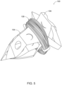
- the roll of material 108 is removable from the arbor 102 (see FIG. 5 ).
- the arbor 102 extends about an arbor axis 90.
- the arbor axis 90 extends through a radial center of the arbor 102.
- the arbor 110 includes a plurality of arbor panels 110. Each of the arbor panels 110 is connected to each of the other arbor panels 110 in series. For example, a first arbor panel 110a is connected to a second arbor panel 110b.
- the plurality of arbor panels 110 comprises four panels (as illustrated), such that the arbor 102 forms a substantially rectangular cross-sectional shape when viewed along the arbor axis A. It will be appreciated that the arbor 102 can comprise a different number of panels. For example, the arbor 102 can comprise three panels or five or more panels.
- Each of the arbor panels 110 includes a first arbor edge 112 and a second arbor edge 114. Each of the first arbor edges 112 is spaced from the respective second arbor edge 114 in an arbor direction A. The arbor direction A is substantially parallel to the arbor axis 90.
- Each of the arbor panels 110 further includes a third arbor edge 115 and a fourth arbor edge 117.
- the third arbor edge 115 of an arbor panel 110 is connected to a corresponding fourth arbor edge 117 of an adjacent arbor panel 110.
- the third arbor edge 115 of the first arbor panel 110a is connected to the fourth arbor edge 117 of the second arbor panel 110b.
- the third arbor edge 115 of the second arbor panel 110b is connected to a fourth arbor edge 117 of a third arbor panel 110c (see FIG. 4A ).
- each arbor panel 110 extends in a direction substantially parallel to the arbor axis 90.
- the first, second, third, and fourth arbor edges 112, 114, 115, and 117 can define a substantially rectangular arbor panel 110.
- the third and fourth arbor edges 115 and 117 are angularly offset from one another (e.g. not substantially parallel to one another), such that each arbor panel 110 includes a trapezoid shape, rhombus shape, combinations thereof, or other quadrilateral shape.
- each arbor panel 110 can include fewer or more than four arbor edges and can define a triangular shape, hexagon shape, combinations thereof, or other shape.
- each arbor panel 110 is substantially planar such that each arbor edge (e.g. edges 112, 114, 115, and 117) extends along a substantially similar plane.
- the connection between the respective third and fourth arbor edges 115 and 117 of adjacent arbor panels 110 can include a crease line.
- the crease line can include a fold or bend in the spool 100 material.
- the crease line can allow each arbol panel 110 to rotate relative to an adjacent arbor panel 100 about the crease line. It will be appreciated that the connection between respective third and fourth arbor edges 115 and 117 can comprise other types of rotatable connections that allow the arbor panels 110 to rotate relative to adjacent arbor panels 110.
- the first arbor edge 112 of each arbor panel 110 is rotatably connected to the first flange 104.
- the rotatable connection between each first arbor edge 112 and the first flange 104 can include a crease line.
- the crease line can include a fold or bend in the spool 100 material.
- the first arbor edge 112 of every arbor panel 110 is rotatably connected to the first flange 104.
- fewer than all the first arbor edges 112 of each arbor panel 110 are connected to the first flange 104.
- an arbor 102 that includes four arbor panels 110 can have two first arbor edges 112 of two of the arbor panels 110 connected to the first flange 106, while two first arbor edges 112 of two of the other arbor panels 110 are not connected to the first flange 104.
- the second arbor edge 114 of each arbor panel 110 is rotatably connected to the second flange 106.
- the rotatable connection between each second arbor edge 114 and the second flange 106 can include a crease line.
- the crease line can include a fold or bend in the spool 100 material.
- the second arbor edge 114 of every arbor panel 110 is rotatably connected to the second flange 106.
- fewer than all the second arbor edges 114 of each arbor panel 110 are connected to the second flange 104.
- an arbor 102 that includes four arbor panels 110 can have two second arbor edges 114 of two of the arbor panels 110 connected to the second flange 106, while two second arbor edges 114 of two of the other arbor panels 110 are not connected to the second flange 106.
- connection between the first arbor edges 112 of each arbor panel 110 with the first flange 104 and the connection between the second arbor edges 114 of each arbor panel 110 with the second flange 106 can be substantially symmetric when viewed in a direction substantially perpendicular to the arbor axis 90.
- each first arbor edge 112 and each second arbor edge 114 can be connected to the respective first flange and second flange 104 and 106 in a substantially similar manner.
- each arbor panel 110 that has a first arbor edge 112 connected to the first flange 104 has a second arbor edge 114 that is not connected to the second flange 106.
- each arbor panel 110 that has a second arbor edge 114 connected to the second flange 106 has a first arbor edge 112 that is not connected to the first flange 104.
- the first and second flanges 104 and 106 are circumferentially offset from each other when viewed along the arbor axis 90. It will be appreciated that other alternative connections between the arbor panels 110 and the first and second flanges 104 and 106 can be considered that are consistent with the aspects described herein.
- the first flange 104 includes a first plurality of flange panels 116.
- the first plurality of flange panels 116 comprises a first inner plurality of flange panels 118 and a first outer plurality of flange panels 120.
- the first inner plurality of flange panels 118 extend from the arbor 102 to the first outer plurality of flange panels 120.
- the first outer plurality of flange panels 120 extend to an end 121 of the first flange 104.
- Each of the first arbor edges 112 of the arbor panels 110 is rotatably connected to a respective one of the first inner plurality of flange panels 118.
- the first arbor panel 110a is rotatably connected to a first inner flange panel 118a.
- the second arbor panel 110b is rotatably connected to a second inner flange panel 118b.
- Each of the first outer plurality of flange panels 120 is rotatably connected to an edge of a respective one of the first inner plurality of flange panels 118.
- the rotatable connection between each of the panels 110, 118, and 120 can include a crease line formed in the material composing the spool 100.
- each first arbor edge 112 of the arbor panels 110 and the respective one of the first inner plurality of flange panels 118 can extend in a direction that is substantially perpendicular to the arbor axis 90.
- Each of the first inner plurality of flange panels 118 can rotate between at least 90 degrees and 180 degrees relative to the respective arbor panel 110 to which the inner flange panel 118 is connected. For example, when one of the first inner plurality of flange panels 118 is rotated approximately 90 degrees relative to the respective arbor panel 110 to which it is connected, the inner flange panel 118 extends in a direction away from (e.g.
- the inner flange panel 118 extends in a direction substantially parallel to the arbor axis 90.
- the inner flange panel 118 can be substantially planar with (e.g. align along the same plane) the respective arbor panel 110 to which it is connected.
- each of the first inner plurality of flange panels 118 can rotate to an angle relative to the respective arbor panel 110 to which it is connected that is greater than 180 degrees and less than 90 degrees to facilitate receiving and retaining the roll of material 108 onto the arbor 102, as further described below.
- edge 122 can extend at other angles other than substantially perpendicular to the arbor axis 90 when the first inner flange panel is greater than 90 degrees.
- first inner flange panel 118a when the first inner flange panel 118a is positioned at approximately 180 degrees relative to the respective arbor panel 110, the edge 122a can extend at an angle other than substantially perpendicular to the arbor axis 90.
- the first plurality of flange panels 116 further includes the second inner flange panel 118b and a second outer flange panel 120b rotatably connected to the second inner flange panel 118b at an edge 122b.
- the second inner flange panel 118b can be connected to the second outer flange panel 120b in a substantially similar manner as the first inner flange panel 118a is connected to the second outer flange panel 120a as described above.
- the first outer flange panel 120a is rotatably connected to the second outer flange panel 120b.
- the rotatable connection between the first and second outer flange panels 120a and 120b is defined by a crease line 124.
- the first plurality of flange panels 116 can further include a third inner flange panel 118c, a fourth inner flange panel 118d, a third outer flange panel 120c, and a fourth outer flange panel 120d.
- the third and fourth inner flange panels 118c and 118d and the third and fourth outer flange panels 120c and 120d can be configured substantially similarly to the first and second inner flange panels 118a and 118b and the first and second outer flange panels 120a and 120b, respectively.
- Each of the third and fourth inner flange panels 118c and 118d can extend from a respective first arbor edge 112 of the arbor.
- Each of the third and fourth outer flange panels 120c and 120d can extend from the respective third and fourth inner flange panels 118c and 118d.
- the first and second outer flange panels 120a and 120b can be configured to connect with the third and fourth outer flange panels 120c and 120d.
- either or both of the first and second outer flange panels 120a and 120b can include a first connect element 126.
- Either or both of the third and fourth outer flange panels 120c and 120d can include a second connect element 128.
- the first and second connect elements 126 and 128 are configured to connect to one another to selectively retain the first flange 104 in the retention configuration.
- the first and second connect elements 126 and 128 can include, for example, Velcro connectors, a protrusion and slot connection, snap connection, or other type of connection to selectively connect the first and second outer flange panels 120a and 120b with the third and fourth outer flange panels 120c and 120d.
- At least one of the first plurality of inner flange panels 118 can be configured to connect with a respective one of the first plurality of outer flange panels 120.
- the connection between at least one of the first plurality of inner flange panels 118 and the respective one of the first plurality of outer flange panels 120 can selectively retain the first flange 104 in the retention configuration, as further described below.
- the first flange 104 is configured to transition between the retention configuration (see FIGS. 2 and 6 ) and the open configuration (see FIGS. 4A , 4B , and 5 ).
- the first and second inner flange panels 118a and 118b extend from the respective first arbor edges 112 to a retention height R.
- the first and second inner flange panels 118a and 118b extend from the respective first arbor edges 112 to an open height.
- the retention height and the open height extend in a flange direction B from the arbor axis 90.
- the flange direction B is substantially perpendicular to the arbor axis 90.
- the retention height is greater than the open height to allow the roll of material 108 to be inserted onto and about the arbor 102 (see FIG. 5 ).
- an outer cross-sectional dimension of the first plurality of flange panels 116 is less than an inner cross-sectional dimension of the roll of material 108.
- at least one of the first inner plurality of flange panels 118 is positioned relative to the respective arbor panel to which it is connected at an angle of less than approximately 90 degrees.
- each of the first inner plurality of flange panels 118 is positioned relative to the respective arbor panel to which it is connected at an angle of approximately 180 degrees.
- the roll of material 108 is removable from the arbor 102 in the arbor direction A along the arbor axis 90.
- the roll of material 108 is substantially prevented from removal from the arbor 102 along the arbor axis 90 by the first and second flanges 104 and 106 (see FIG. 6 ).
- an outer cross-sectional dimension of the first plurality of flange panels 116 is greater than an inner cross-sectional dimension of the roll of material 108.
- at least one of the first inner plurality of flange panels 118 is positioned relative to the respective arbor panel to which it is connected at an angle of approximately 90 degrees.
- the roll of material 108 can be retained on the arbor 102 when at least one of the first inner plurality of flange panels 118 is at an angle of less than approximately 90 degrees relative to the arbor panel 110 to which it is connected if the outer cross-sectional dimension of the first inner plurality of flange panels 118 is greater than an inner cross-sectional dimension of the roll of material 108.
- the first flange 104 can be transitioned from the retention configuration to the open configuration by rotating one or more of the first plurality of flange panels 116.
- the first and second inner flange panels 118a and 118b can be rotated from approximately 90 degrees relative to the respective arbor edge 112 to an angle of greater than approximately 90 degrees.
- the first and second inner flange panels 118a and 118b can be rotated to approximately 180 degrees. Rotation of the first and second inner flange panels 118a and 118b causes the respective first and second outer flange panels 120a and 120b to rotate about the respective edges 122a and 122b.
- the first flange 104 extends axial outward from the arbor 102 in the arbor direction A.
- the roll of material can be positioned on the arbor 102 by moving the roll of material along the arbor axis 90.
- the first and second inner flange panels 118a and 118b are rotated toward the 90 degree position relative to the respective arbor panel 110.
- the first flange 104 retracts axially inward toward the arbor 102 in a direction opposite the arbor direction A.
- the roll of material 108 is retained on the arbor 102.
- the first flange 102 can be selectively retained in the retention configuration by connected the first connect element 126 to the second connect element 128.
- a surface of the first outer flange panel 120a abuts against a surface of the first inner flange panel 118a
- a surface of the second outer flange panel 120b abuts against a surface of the second inner flange panel 118b.
- One or both of the sets of abutting surfaces of the first inner and outer flange panels 118a and 120a and the second inner and outer flange panels 118b and 120b can include connect elements (see e.g. FIG. 22 - snap feature) to selectively connect the abutting surfaces together.
- the selective connection between the abutting surfaces can selectively retain the first flange 104 in the retention configuration.
- third and fourth inner flange panels 118c and 118d and the third and fourth outer flange panels 120c and 120d can be moved and/or transitioned substantially similarly as the first and second inner flange panels 118a and 118b and the first and second outer flange panels 120a and 120b to transition the first flange 104 between the retention configuration and the open configuration.
- the second flange 106 can be configured substantially similarly to the first flange 104.
- the second flange 106 can include a second plurality of flange panels 132.
- the second plurality of flange panels 132 can transition the second flange 106 between a retention configuration to retain the roll of material 108 on the arbor 102, and an open configuration to allow the arbor 102 to receive the roll of material 108 and to allow the roll of material 108 to be removed from the arbor 102.
- the first and second flanges 104 and 106 can be configured differently from one another.
- the second flange 106 can be configured such that the second flange is retained or locked in the retention position.
- the first flange 104 is selectively transitioned between the retention and open configurations.
- the connect elements 126 and 128 can be located on different panels of either of the first and second flanges 104 and 106.
- the spool 100 could have fewer or more inner panels and/or fewer or more outer panels configured to transition between retention and open configurations.
- each of the outer flange panels 120 can be connected to each adjacent outer flange panel 120.
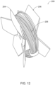
- FIGS. 7 through 13 illustrate a spool 200, according to an alternative aspect of this disclosure.
- the spool 200 can be transitioned, aligned, and configured in a substantially similar manner as the spool 100 described herein.
- the spool 200 includes an arbor 202, a first flange 204, and a second flange 206.
- the arbor member 202 and the first and second flanges 204 and 206 can be integrally formed as a single unitary piece.
- the first and/or the second flange 204 and 106 can transition between an open position and a retention position without removing either the first and the second flange 204 and 206 from the arbor 202.
- the spool 200 can comprise a paperboard material.
- a first outer panel 120a of a plurality of first flange panels 216 includes a first connect element 226.
- the first connect element 226 defines a first aperture 230 that extends therethrough.
- a third outer panel 120c of the plurality of the first flange panels 216 includes a second connect element 228 that defines a second aperture 232 that extends therethrough.
- the first aperture 230 can substantially align with the second aperture 232 along an arbor axis 190.
- the spool 200 can include a dowel member (not shown).
- the dowel member can be configured to extend through the arbor 202, the first aperture 230, and the second aperture 232 along the arbor axis 190 when the first flange 204 is in the retention configuration.
- the second flange 206 can be configured substantially similarly to the first flange 204.
- the dowel member can further extend through first and second apertures (not shown) of the second flange 206.
- the dowel member can allow the spool to rotate about the arbor axis 190 such that a roll of material 208 can be wound about the arbor 202 by rotating the spool 200 about the arbor axis 190 in a coil direction. Similarly, the roll of material 208 can be unwound from the arbor 202 by rotating the spool 200 about the arbor axis 190 in a direction opposite the coil direction.
- FIGS. 14 through 17 illustrate a spool 300, according to an alternative aspect of this disclosure. It will be appreciated that the spool 300 can be transitioned, aligned, and configured in a substantially similar manner as either of the spools 100 and 200 described herein.
- the spool 300 includes an arbor 302, a first flange 304, and a second flange 306.
- the first arbor edge of both the first and third arbor panels 310a and 310c is rotatably connected to a respective flange panel of a plurality of flange panels 316.
- a second arbor panel 310b of the plurality of arbor panels 310 is positioned circumferentially between the first and third arbor panels 310a and 310c.
- the second arbor panel 310b includes a second arbor edge that is connected to the second flange 306.
- the configuration of the plurality of arbor panels 310 can circumferentially offset the first flange 304 from the second flange 306 when viewed along the arbor axis 290 (see FIG. 15 ).
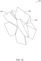
- FIGS. 18 through 21 illustrate a spool 400, according to an alternative aspect of this disclosure. It will be appreciated that the spool 400 can be transitioned, aligned, and configured in a substantially similar manner as any of the spools 100, 200, and 300 described herein.
- the spool 400 includes an arbor 402, a first flange 404, and a second flange 406 constructed of a single piece of paperboard material.
- FIG. 22 illustrates a top view of a spool 500 in an unassembled configuration, according to an aspect of this disclosure. It will be appreciated that the spool 500 can be transitioned, aligned, and configured in a substantially similar manner as any of the spools 100, 200, 300, and 400 described herein.
- the spool 500 comprises a one-piece paperboard blank 501.
- the blank 501 can be assembled to form an arbor 502, a first flange 504, and a second flange 506.
- the method of assembling the spool 500 includes forming crease lines 511 in the blank 501 between each of the plurality of arbor panels 510.
- Each of the crease lines 511 can allow each arbor panel 510 to rotate relative to an adjacent arbor panel 510.
- Crease lines 513 can be formed between each of the plurality of arbor panels 510 and respective inner flange panels of a plurality of inner flange panels 518.
- Each of the crease lines 513 can allow each of the plurality of inner flange panels 518 to rotate relative to a respective one of the plurality of arbor panels 510.
- Crease lines 515 can be formed between each of the plurality of inner flange panels 518 and respective outer flange panels of a plurality of outer flange panels 520.
- Each of the crease lines 515 can allow each of the plurality of outer flange panels 520 to rotate relative to a respective one of the plurality of inner flange panels 518.
- a crease line (see e.g. crease line 124 in FIG. 2 ) can be formed between adjacent outer flange panels 520 to allow adjacent outer flange panels 520 to rotate relative to each other.
- a first arbor panel 510a of a plurality of arbor panels 510 can be connected to a second arbor panel 510b of the plurality of arbor panels 510.
- the spool 500 is transitionable between the open configuration and the retention configuration.
- FIGS. 23-27 illustrate a spool 2, according to another alternative aspect of this disclosure.
- Spool 2 generally includes a barrel 4 (e.g. an arbor), a fixed flange 6, and a collapsible flange 8.
- Collapsible flange 8 can be configured in a collapsed condition as shown in FIG. 27 which allows a coiled item to be slid over flange 8 onto barrel 4.
- the coiled item can be a coil of thread, cord, wire, rope, or line.
- Fishing line such as fly fishing line can be stored on spool 2.
- Spool 2 defines a central opening 10 that allows it be rotatable mounted or stored on a hanger.
- the spool 2 can include multiple collapsible flanges.
- both of the fixed flange 6 and the collapsible flange 8 can be configured to transition to a collapsed condition to receive a coiled item to be slid over the respective flange.
- Spool 2 can be folded into the intermediate condition of FIG. 24 and then the erected position of FIGS. 25-28 from the flat condition of FIG. 23 .
- the flat condition of FIG. 23 can be cut from a flat piece of material such as a paper, a paperboard, or a polymer board.
- the foldable material is a 0.018 Solid Bleached Sulphate (SBS) paperboard.
- SBS Solid Bleached Sulphate
- Adhesive is used to hold portions together as marked with wavy lines in FIG. 23 and as marked. It will be appreciated that the spool 2 can be held together in other ways than adhesive (e.g. snap-fits, interference fits, mechanical interlocking, etc.).
- Spool 2 can be made from a recyclable paper or polymer material. In other configurations, the elements of spool 2 can be formed separated and joined.
- Spool 2 can be erected from the flat condition shown in FIG. 23 into an intermediate condition of FIG. 24 wherein all of the connections (e.g. adhesive connections) have been made but barrel 4 has not been completed.
- the walls that used to form barrel 4 are disposed as two parallel members that allows collapsible flange 8 to pivot down until portions of its inner surface engage portions of the inner surface of fixed flange 6.
- spool 2 is substantially flat which is desired for storage and shipping.
- the user finishes the erection of spool 2 by pivoting collapsible flange 8 up away from fixed flange 6 until the walls that are used to form barrel 4 are substantially perpendicular to flanges 6 and 8.
- the barrel half walls are folded toward each other and their ends are interlocked to complete the erection of spool 2.
- spool 2 can be loaded with a coiled item either by winding the item around barrel or by sliding the coiled item over collapsible flange 8.
- Some coiled items such as fly fishing line are coiled during manufacturing and it is not desirable to uncoil the line from its condition and rewind it onto barrel 4.
- collapsible flange 8 can be changed to its collapsed condition shown in FIG. 27 , which allows the coiled item to be slid over collapsed flange 8 and onto barrel 4.
- flange 8 has a cross section (taken perpendicular to the axis of rotation of spool 2) that less than or equal to the cross section of barrel 4.
- Collapsed flange 8 may be tapered down along its length to provide for easy loading of coiled items. After the coiled item is loaded onto barrel 4, collapsible flange 8 is returned to the erected condition shown in FIGS. 25 and 26 to retain the coiled item on spool 2.
- Barrel 4 includes four walls 20, 22, 24, and 26 with walls 22 and 26 being formed by barrel half walls 28 that have mechanically interlocking end portions 30.
- a user can optionally use adhesive to secure the interlocking end portions 30.
- the interlocking end portions 30 can include, for example, corresponding snap-fits, interference fits, or other corresponding connection or interlocking portions.
- Fixed flange 6 includes two main layers and an attachment flange 32 used to anchor barrel wall 24. Attachment flange is adhered to a portion of the inner surface of flange 6 inside barrel 4.
- the two main layers of flange 6 include an outer panel 34 (defining a portion of opening 10) and first 36 and second 38 inner panels which are folded against and adhered to outer panel 34. First inner panel overlaps and defines a portion of opening 10.
- Barrel wall 20 is connected to an inner end of second inner panel 38.
- Flange 6 can be octagonal.
- Collapsible flange 8 includes two main layers defined by an outer panel 44 and first 46 and second 48 inner panels which are adhered to outer panel.
- First inner panel 46 is connected to the top of barrel wall 20 and second inner panel 48 is connected to the top of barrel wall 24.
- Collapsible flange 8 can include a rectangular or square central portion 50 from which four tapered subpanels 52 extend. It will be appreciated that fewer or more subpanels 52 can extend from the central portion 50.
- FIGS. 23 and 24 illustrate the tapered sides of subpanels 52. The tapered sides of subpanels 52 can facilitate the insertion of the fishing line when the spool 2 is in the collapsed condition.
- Folding corner panels 54 connect the later edges of subpanels 52 and define a corner relief. When flange 8 is collapsed, folding corner panels 54 are folded inward as shown in FIG. 27 such that subpanels are disposed at or within the cross sectional perimeter of barrel 4. The folding corner panels can minimize tangling, bending, or other damage to the filament positioned about the barrel 4.
- the spool assemblies disclosed herein can comprise a single piece paperboard spool that is eco-friendly and solves the short comings of the multiple piece spool designs.
Landscapes
- Storage Of Web-Like Or Filamentary Materials (AREA)
Claims (15)
- Spule (100, 200, 300, 400, 500, 2) zum Tragen einer Materialrolle (108, 208), wobei die Spule Folgendes umfasst:einen Dorn (102, 202, 302, 402, 502, 4), der sich um eine Dornachse (90, 190, 290) erstreckt, wobei der Dorn mehrere Dornplatten (110, 310, 510, 20, 24, 28) umfasst, die miteinander verbunden und um die Dornachse beabstandet sind, wobei eine erste (110a, 310a, 510a) und eine zweite Dornplatte (110b, 310c, 510b) der mehreren Dornplatten jeweils eine erste Dornkante (112) umfassen, und wobei eine dritte Dornplatte (110c, 310b) der mehreren Dornplatten eine zweite Dornkante (114) umfasst, wobei die ersten Dornkanten der ersten und der zweiten Dornplatte von der zweiten Dornkante der dritten Platte in einer Dornrichtung beabstandet sind, wobei die Dornrichtung im Wesentlichen parallel zur Dornachse ist;einen ersten Flansch (104, 204, 304, 404, 504, 8), der mehrere erste Flanschplatten (116, 216, 316, 518, 520) umfasst, wobei eine erste Flanschplatte (118a) der mehreren ersten Flanschplatten drehbar mit der ersten Dornkante der ersten Dornplatte verbunden ist, und wobei eine zweite Flanschplatte (118b) der mehreren ersten Flanschplatten drehbar mit der ersten Dornkante der zweiten Dornplatte verbunden ist; undeinen zweiten Flansch (106, 206, 306, 406, 506, 6), der mit der zweiten Dornkante der dritten Dornplatte verbunden sind, unddadurch gekennzeichnet, dass der erste Flansch dazu ausgelegt ist, zwischen einer Haltekonfiguration und einer offenen Konfiguration überzugehen, wobei in der Haltekonfiguration sich die erste und die zweite Flanschplatte der mehreren ersten Flanschplatten von den jeweiligen ersten Dornkanten zu einer Haltehöhe (R) erstrecken, und wobei in der offenen Konfiguration sich die erste und die zweite Flanschplatte der mehreren ersten Flanschplatten von den jeweiligen ersten Dornkanten zu einer offenen Höhe erstrecken, wobei sich die Haltehöhe und die offene Höhe in einer Flanschrichtung (B) erstrecken, wobei die Flanschrichtung im Wesentlichen senkrecht zur Dornachse ist, undwobei die Haltehöhe größer als die offene Höhe ist, wobei in der Haltekonfiguration die Materialrolle durch den ersten und den zweiten Flansch im Wesentlichen daran gehindert wird, entlang der Dornachse von dem Dorn entfernt zu werden, und wobei in der offenen Konfiguration die Materialrolle in der Dornrichtung von dem Dorn entfernbar ist.
- Spule nach Anspruch 1, wobei die erste, die zweite und die dritte Dornplatte im Wesentlichen planar sind, und wobei die erste und die zweite Flanschplatte der mehreren ersten Flanschplatten im Wesentlichen planar sind.
- Spule nach Anspruch 2, wobei der Dorn ferner eine vierte Dornplatte der mehreren Dornplatten umfasst, wobei die erste, die zweite, die dritte und die vierte Dornplatte in Reihe um die Dornachse miteinander verbunden sind, wodurch bei Ansicht entlang der Dornachse eine im Wesentlichen rechteckige Querschnittsform gebildet wird.
- Spule nach Anspruch 2, wobei die erste, die zweite und die dritte Dornplatte (310a, 310b, 310c) jeweils eine im Wesentlichen dreieckige Form umfassen, wobei die dritte Dornplatte in Umfangsrichtung zwischen der ersten und der zweiten Dornplatte positioniert ist, wobei die dritte Dornplatte ferner eine erste Innenkante und eine zweite Innenkante umfasst, wobei die erste Innenkante mit der ersten Dornplatte verbunden ist und die zweite Innenkante mit der zweiten Dornplatte verbunden ist.
- Spule nach Anspruch 1, wobei der erste Flansch zwischen der Haltekonfiguration und der offenen Konfiguration übergehen kann, indem die erste und die zweite Flanschplatte der mehreren ersten Flanschplatten um die jeweiligen ersten Dornkanten der ersten und der zweiten Dornplatte gedreht werden.
- Spule nach Anspruch 1, wobei die Spule ein Pappmaterial umfasst, wobei optional die drehbare Verbindung zwischen der ersten Flanschplatte der mehreren ersten Flanschplatten und der ersten Dornkante der ersten Dornplatte eine Falzlinie in dem Pappmaterial umfasst, und wobei die drehbare Verbindung zwischen der zweiten Flanschplatte der mehreren ersten Flanschplatten und der ersten Dornkante der zweiten Dornplatte eine Falzlinie in dem Pappmaterial umfasst.
- Spule nach Anspruch 1, wobei die erste Flanschplatte der mehreren ersten Flanschplatten eine erste innere Flanschplatte (118a, 518) ist, und wobei die zweite Flanschplatte der mehreren ersten Flanschplatten eine zweite innere Flanschplatte (118a, 518) ist, wobei die Spule ferner Folgendes umfasst:eine erste äußere Flanschplatte (120a, 520) der mehreren ersten Flanschplatten, die drehbar mit einer Kante (122a) der ersten inneren Flanschplatte verbunden ist; undeine zweite äußere Flanschplatte (120b, 520) der mehreren ersten Flanschplatten, die drehbar mit einer Kante (122b) der zweiten inneren Flanschplatte verbunden ist,wobei die erste äußere Flanschplatte drehbar mit der zweiten äußeren Flanschplatte verbunden ist.
- Spule nach Anspruch 7, wobei in der Haltekonfiguration des ersten Flansches 1.) eine Oberfläche der ersten äußeren Flanschplatte (120a) an einer Oberfläche der ersten inneren Flanschplatte (118a) anliegt, 2.) eine Oberfläche der zweiten äußeren Flanschplatte (120b) an einer Oberfläche der zweiten inneren Flanschplatte (118b) anliegt und 3.) sich die drehbare Verbindung zwischen der ersten äußeren Flanschplatte und der zweiten äußeren Flanschplatte entlang einer Linie in einem Winkel von ungefähr 45 Grad relativ zu der ersten Dornkante erstreckt.
- Spule nach Anspruch 7, wobei der Dorn ferner eine vierte Dornplatte der mehreren Dornplatten umfasst, wobei die erste, die zweite, die dritte und die vierte Dornplatte in Reihe um die Dornachse miteinander verbunden sind, wobei die Spule ferner Folgendes umfasst:eine dritte innere Flanschplatte (118c) der mehreren ersten Flanschplatten, die drehbar mit einer ersten Dornkante der dritten Dornplatte verbunden ist;eine vierte innere Flanschplatte (118d) der mehreren ersten Flanschplatten, die drehbar mit einer ersten Dornkante der vierten Dornplatte verbunden ist;eine dritte äußere Flanschplatte (120c) der mehreren ersten Flanschplatten, die drehbar mit einer Kante der dritten inneren Flanschplatte verbunden ist; undeine vierte äußere Flanschplatte (120d) der mehreren ersten Flanschplatten, die drehbar mit einer Kante der vierten inneren Flanschplatte verbunden ist,wobei die dritte äußere Flanschplatte drehbar mit der vierten äußeren Flanschplatte verbunden ist.
- Spule nach Anspruch 7, wobei die erste äußere Flanschplatte ein erstes Verbindungselement (126) umfasst, und wobei die zweite äußere Flanschplatte ein zweites Verbindungselement (128) umfasst, wobei in der Haltekonfiguration des ersten Flansches das erste Verbindungselement dazu konfiguriert ist, mit dem zweiten Verbindungselement verbunden zu sein, um den ersten Flansch selektiv in der Haltekonfiguration zu halten.
- Spule nach Anspruch 9, wobei die erste und/oder die zweite äußere Flanschplatte eine erste Öffnung (230) definiert, und wobei die dritte und/oder die vierte äußere Flanschplatte eine zweite Öffnung (232) definiert, wobei in der Haltekonfiguration des ersten Flansches die erste Öffnung entlang der Dornachse im Wesentlichen mit der zweiten Öffnung ausgerichtet ist, optional ferner umfassend ein Dübelelement, das dazu konfiguriert ist, sich entlang der Dornachse durch den Dorn, die erste Öffnung und die zweite Öffnung zu erstrecken, wenn sich der erste Flansch in der Haltekonfiguration befindet.
- Spule nach Anspruch 1, wobei der zweite Flansch mehrere zweite Flanschplatten (132) umfasst, wobei eine erste Flanschplatte der mehreren zweiten Flanschplatten drehbar mit einer zweiten Dornkante der ersten Dornplatte verbunden ist, wobei eine zweite Flanschplatte der mehreren zweiten Flanschplatten drehbar mit einer zweiten Dornkante der zweiten Dornplatte verbunden ist, und wobei eine dritte Flanschplatte der mehreren zweiten Flanschplatten drehbar mit der zweiten Dornkante der dritten Dornplatte verbunden ist,
wobei der zweite Flansch dazu konfiguriert ist, zwischen einer Haltekonfiguration und einer offenen Konfiguration überzugehen, wobei in der Haltekonfiguration des zweiten Flansches sich die erste, die zweite und die dritte Flanschplatte der mehreren zweiten Flanschplatten von den jeweiligen zweiten Dornkanten zu der Haltehöhe erstrecken, und wobei in der offenen Konfiguration sich die erste, die zweite und die dritte Flanschplatte der mehreren zweiten Flanschplatten von den jeweiligen zweiten Dornkanten zu der offenen Höhe erstrecken. - Verfahren zum Zusammenbauen einer Pappspule (100, 200, 300, 400, 500) aus einem einstückigen Pappzuschnitt (501), wobei das Verfahren Folgendes umfasst:Verbinden einer ersten Dornplatte (110a, 310a, 510a) mehrerer Dornplatten (110, 310, 510) mit einer zweiten Dornplatte (110b, 310b, 510b) der mehreren Dornplatten, wobei die erste und die zweite Dornplatte mindestens einen Abschnitt eines Dorns bilden, der sich um eine Dornachse erstreckt;Bilden einer ersten Flanschplattenfalzlinie (513) zwischen der ersten Dornplatte und einer ersten Flanschplatte (116) mehrerer erster Flanschplatten (116, 216, 316, 518, 520), so dass die erste Flanschplatte relativ zu der ersten Dornplatte drehbar ist; undBilden einer zweiten Flanschplattenfalzlinie (513) zwischen der zweiten Dornplatte und einer zweiten Flanschplatte der mehreren ersten Flanschplatten, so dass die zweite Flanschplatte relativ zu der zweiten Dornplatte drehbar ist,dadurch gekennzeichnet, dass die mehreren ersten Flanschplatten einen ersten Flansch (104, 204, 304, 404, 504) bilden, der dazu konfiguriert ist, zwischen einer Haltekonfiguration und einer offenen Konfiguration überzugehen, wobei in der Haltekonfiguration sich die erste und die zweite Flanschplatte der mehreren ersten Flanschplatten von der jeweiligen ersten und zweiten Dornkante zu einer Haltehöhe (R) erstrecken, und wobei in der offenen Konfiguration sich die erste und die zweite Flanschplatte der mehreren ersten Flanschplatten von der jeweiligen ersten und zweiten Dornkante zu einer offenen Höhe erstrecken, wobei sich die Haltehöhe und die offene Höhe in einer Flanschrichtung von der Dornachse erstrecken, wobei die Flanschrichtung im Wesentlichen senkrecht zur Dornachse ist, undwobei die Haltehöhe größer als die offene Höhe ist, wobei in der Haltekonfiguration die Materialrolle durch den ersten Flansch und einen zweiten Flansch (106, 206, 306, 406, 506) im Wesentlichen daran gehindert wird, entlang der Dornachse von dem Dorn entfernt zu werden, wobei der erste Flansch entlang einer Dornrichtung von dem zweiten Flansch beabstandet ist, die im Wesentlichen parallel zur Dornachse ist, und wobei in der offenen Konfiguration die Materialrolle entlang der Dornachse in der Dornrichtung von dem Dorn entfernbar ist.
- Verfahren nach Anspruch 13, ferner umfassend:
Bilden einer ersten Dornfalzlinie (511) zwischen der zweiten Dornplatte und einer dritten Dornplatte der mehreren Dornplatten, wobei die erste, die zweite und die dritte Dornplatte mindestens einen Abschnitt des Dorns bilden, optional ferner umfassend:Bilden einer zweiten Dornfalzlinie (511) zwischen der dritten Dornplatte und einer vierten Dornplatte der mehreren Dornplatten, wobei die erste, die zweite, die dritte und die vierte Dornplatte mindestens einen Teil des Dorns bilden; undBilden einer dritten Dornfalzlinie (511) zwischen der vierten Dornplatte und der ersten Dornplatte, ferner, wobei optional sich die erste, die zweite, die dritte und die vierte Dornplatte um die Dornachse erstrecken, wodurch bei Ansicht entlang der Dornachse eine im Wesentlichen rechteckige Querschnittsform gebildet wird. - Verfahren nach Anspruch 13, wobei die erste Flanschplatte der mehreren ersten Flanschplatten eine erste innere Flanschplatte ist, und wobei die zweite Flanschplatte der mehreren ersten Flanschplatten eine zweite innere Flanschplatte ist, wobei das Verfahren ferner Folgendes umfasst:Bilden einer dritten Flanschplattenfalzlinie (515) zwischen der ersten inneren Flanschplatte und einer ersten äußeren Flanschplatte der mehreren ersten Flanschplatten, so dass die erste äußere Flanschplatte relativ zu der ersten inneren Flanschplatte drehbar ist; undBilden einer vierten Flanschplattenfalzlinie (515) zwischen der zweiten inneren Flanschplatte und einer zweiten äußeren Flanschplatte der mehreren ersten Flanschplatten, so dass die zweite äußere Flanschplatte relativ zu der zweiten inneren Flanschplatte drehbar ist, optional ferner umfassend:
Bilden einer fünften Flanschplattenfalzlinie (124) zwischen der ersten äußeren Flanschplatte und der zweiten äußeren Flanschplatte, so dass die erste äußere Flanschplatte relativ zu der zweiten äußeren Flanschplatte drehbar ist.
Applications Claiming Priority (3)
| Application Number | Priority Date | Filing Date | Title |
|---|---|---|---|
| US202063111465P | 2020-11-09 | 2020-11-09 | |
| US202063113592P | 2020-11-13 | 2020-11-13 | |
| US202163163248P | 2021-03-19 | 2021-03-19 |
Publications (3)
| Publication Number | Publication Date |
|---|---|
| EP3995423A1 EP3995423A1 (de) | 2022-05-11 |
| EP3995423B1 true EP3995423B1 (de) | 2025-07-02 |
| EP3995423C0 EP3995423C0 (de) | 2025-07-02 |
Family
ID=78516586
Family Applications (1)
| Application Number | Title | Priority Date | Filing Date |
|---|---|---|---|
| EP21206146.9A Active EP3995423B1 (de) | 2020-11-09 | 2021-11-03 | Spulenanordnung und verfahren zur montage |
Country Status (4)
| Country | Link |
|---|---|
| US (2) | US11939184B2 (de) |
| EP (1) | EP3995423B1 (de) |
| JP (1) | JP2022076464A (de) |
| CA (1) | CA3137471A1 (de) |
Families Citing this family (1)
| Publication number | Priority date | Publication date | Assignee | Title |
|---|---|---|---|---|
| JP2022076464A (ja) * | 2020-11-09 | 2022-05-19 | サイエンティフィック アングラーズ リミテッド ライアビリティ カンパニー | スプール組立体および組立方法 |
Family Cites Families (23)
| Publication number | Priority date | Publication date | Assignee | Title |
|---|---|---|---|---|
| US811899A (en) * | 1905-07-14 | 1906-02-06 | Friedenwald Company Of Baltimore City | Collapsible reel. |
| US811898A (en) * | 1905-07-14 | 1906-02-06 | Friedenwald Company Of Baltimore City | Collapsible reel. |
| US1036643A (en) * | 1910-07-22 | 1912-08-27 | American Steel & Wire Co | Collapsible reel for wire. |
| US1205906A (en) * | 1915-07-22 | 1916-11-21 | Claude C Chadwick | Reel. |
| US2112209A (en) | 1936-05-08 | 1938-03-22 | Gen Ribbon Mills Inc | Spool for ribbons and other narrow fabrics |
| US2369958A (en) * | 1942-04-23 | 1945-02-20 | Juliann Whitehill Funke | Foldable reel for narrow fabrics |
| US2852206A (en) * | 1956-04-24 | 1958-09-16 | Standard Packaging Corp | Spool |
| US3104077A (en) * | 1960-10-25 | 1963-09-17 | Diamond National Corp | Collapsible paperboard spool |
| US3101846A (en) * | 1961-06-02 | 1963-08-27 | Stephen L Eifrid | Reel assembly |
| US3284022A (en) * | 1963-11-26 | 1966-11-08 | Stephen L Eifrid | Collapsible reels |
| US3384140A (en) * | 1966-08-29 | 1968-05-21 | Brothers Jack | Hose reel |
| US3554460A (en) | 1968-10-07 | 1971-01-12 | Corning Glass Works | One-piece reel |
| JPS489496Y1 (de) * | 1969-02-17 | 1973-03-13 | ||
| US3817475A (en) * | 1972-06-09 | 1974-06-18 | M Goldstein | Collapsible reel |
| US4019692A (en) * | 1975-12-18 | 1977-04-26 | Champion International Corporation | Reinforced reel |
| US4437618A (en) * | 1982-07-08 | 1984-03-20 | Champion International Corporation | Spool dispenser |
| US4492350A (en) * | 1983-10-17 | 1985-01-08 | Pioneer Packaging, Inc. | Packaging reel |
| JPH053499Y2 (de) * | 1988-03-25 | 1993-01-27 | ||
| US5513819A (en) * | 1994-06-13 | 1996-05-07 | Orange; David A. | Flanged reel from a unitary blank |
| US5649677A (en) * | 1994-09-20 | 1997-07-22 | Culp; Barney L. | Collapsible spool |
| US20100243790A1 (en) | 2007-11-12 | 2010-09-30 | Ates Oemer | One piece reel made by folding of a planar sheet |
| US8882017B2 (en) * | 2011-01-26 | 2014-11-11 | Vail Industries, Inc. | Double flange corrugated reel |
| JP2022076464A (ja) * | 2020-11-09 | 2022-05-19 | サイエンティフィック アングラーズ リミテッド ライアビリティ カンパニー | スプール組立体および組立方法 |
-
2021
- 2021-11-02 JP JP2021179393A patent/JP2022076464A/ja active Pending
- 2021-11-03 EP EP21206146.9A patent/EP3995423B1/de active Active
- 2021-11-03 US US17/518,137 patent/US11939184B2/en active Active
- 2021-11-03 CA CA3137471A patent/CA3137471A1/en active Pending
-
2024
- 2024-02-29 US US18/591,140 patent/US12221315B2/en active Active
Also Published As
| Publication number | Publication date |
|---|---|
| EP3995423A1 (de) | 2022-05-11 |
| US20220144579A1 (en) | 2022-05-12 |
| EP3995423C0 (de) | 2025-07-02 |
| JP2022076464A (ja) | 2022-05-19 |
| CA3137471A1 (en) | 2022-05-09 |
| US20240199369A1 (en) | 2024-06-20 |
| US11939184B2 (en) | 2024-03-26 |
| US12221315B2 (en) | 2025-02-11 |
Similar Documents
| Publication | Publication Date | Title |
|---|---|---|
| EP2077969B1 (de) | Spule für glasfaserkabelanordnungen | |
| US5529186A (en) | Boxed pay-out reel for optic fiber cable or wire or the like, with smooth pay-out, high-impact and cable end holding features | |
| US2706592A (en) | Carton | |
| US5941476A (en) | Portable enclosure for storage and dispensing of multiple paper rolls | |
| US5150789A (en) | Package of elongated strand material and carton blank thereof | |
| US4667824A (en) | Coil package | |
| US11459205B2 (en) | Corrugated cable dispenser | |
| US9771238B2 (en) | Coil package payout tube assembly | |
| US12221315B2 (en) | Spool assembly and method of assembly | |
| US8882017B2 (en) | Double flange corrugated reel | |
| JPH0769537A (ja) | 回転リール装置 | |
| US3278135A (en) | Reel construction | |
| NZ206515A (en) | Package for reel of wire:package stackable and able to dispense wire | |
| WO2022170220A1 (en) | Reusable reel holder and bag with reusable reel holder | |
| JP7692326B2 (ja) | 箱内物品保持構造 | |
| JP4227179B2 (ja) | 抄紙機/板紙抄紙機におけるロール面の保守に使用するドクタブレードの保管箱 | |
| EP4041655B1 (de) | Hülsenzuschnitt, spule und verpackung | |
| US4842216A (en) | Folding cone package design | |
| US11753271B2 (en) | Collapsible/pop-up reel and method of making same | |
| US4003529A (en) | Reel and blank therefor | |
| CA1252434A (en) | Coil package | |
| JP4959681B2 (ja) | ロールハンドリング装置 | |
| WO2022074432A1 (en) | Kit of blanks for forming a reel and a reel formed of such kit of blanks | |
| CZ18106U1 (cs) | Cívka |
Legal Events
| Date | Code | Title | Description |
|---|---|---|---|
| PUAI | Public reference made under article 153(3) epc to a published international application that has entered the european phase |
Free format text: ORIGINAL CODE: 0009012 |
|
| STAA | Information on the status of an ep patent application or granted ep patent |
Free format text: STATUS: THE APPLICATION HAS BEEN PUBLISHED |
|
| AK | Designated contracting states |
Kind code of ref document: A1 Designated state(s): AL AT BE BG CH CY CZ DE DK EE ES FI FR GB GR HR HU IE IS IT LI LT LU LV MC MK MT NL NO PL PT RO RS SE SI SK SM TR |
|
| STAA | Information on the status of an ep patent application or granted ep patent |
Free format text: STATUS: REQUEST FOR EXAMINATION WAS MADE |
|
| 17P | Request for examination filed |
Effective date: 20221111 |
|
| RBV | Designated contracting states (corrected) |
Designated state(s): AL AT BE BG CH CY CZ DE DK EE ES FI FR GB GR HR HU IE IS IT LI LT LU LV MC MK MT NL NO PL PT RO RS SE SI SK SM TR |
|
| P01 | Opt-out of the competence of the unified patent court (upc) registered |
Effective date: 20230523 |
|
| STAA | Information on the status of an ep patent application or granted ep patent |
Free format text: STATUS: EXAMINATION IS IN PROGRESS |
|
| 17Q | First examination report despatched |
Effective date: 20240613 |
|
| 17Q | First examination report despatched |
Effective date: 20240626 |
|
| GRAP | Despatch of communication of intention to grant a patent |
Free format text: ORIGINAL CODE: EPIDOSNIGR1 |
|
| STAA | Information on the status of an ep patent application or granted ep patent |
Free format text: STATUS: GRANT OF PATENT IS INTENDED |
|
| INTG | Intention to grant announced |
Effective date: 20250131 |
|
| GRAS | Grant fee paid |
Free format text: ORIGINAL CODE: EPIDOSNIGR3 |
|
| GRAA | (expected) grant |
Free format text: ORIGINAL CODE: 0009210 |
|
| STAA | Information on the status of an ep patent application or granted ep patent |
Free format text: STATUS: THE PATENT HAS BEEN GRANTED |
|
| AK | Designated contracting states |
Kind code of ref document: B1 Designated state(s): AL AT BE BG CH CY CZ DE DK EE ES FI FR GB GR HR HU IE IS IT LI LT LU LV MC MK MT NL NO PL PT RO RS SE SI SK SM TR |
|
| REG | Reference to a national code |
Ref country code: GB Ref legal event code: FG4D |
|
| REG | Reference to a national code |
Ref country code: CH Ref legal event code: EP |
|
| REG | Reference to a national code |
Ref country code: DE Ref legal event code: R096 Ref document number: 602021033246 Country of ref document: DE |
|
| REG | Reference to a national code |
Ref country code: IE Ref legal event code: FG4D |
|
| U01 | Request for unitary effect filed |
Effective date: 20250721 |
|
| U07 | Unitary effect registered |
Designated state(s): AT BE BG DE DK EE FI FR IT LT LU LV MT NL PT RO SE SI Effective date: 20250725 |
|
| PGFP | Annual fee paid to national office [announced via postgrant information from national office to epo] |
Ref country code: GB Payment date: 20250911 Year of fee payment: 5 |
|
| U20 | Renewal fee for the european patent with unitary effect paid |
Year of fee payment: 5 Effective date: 20251008 |
|
| PG25 | Lapsed in a contracting state [announced via postgrant information from national office to epo] |
Ref country code: IS Free format text: LAPSE BECAUSE OF FAILURE TO SUBMIT A TRANSLATION OF THE DESCRIPTION OR TO PAY THE FEE WITHIN THE PRESCRIBED TIME-LIMIT Effective date: 20251102 |
|
| PGFP | Annual fee paid to national office [announced via postgrant information from national office to epo] |
Ref country code: NO Payment date: 20251113 Year of fee payment: 5 |
|
| PG25 | Lapsed in a contracting state [announced via postgrant information from national office to epo] |
Ref country code: HR Free format text: LAPSE BECAUSE OF FAILURE TO SUBMIT A TRANSLATION OF THE DESCRIPTION OR TO PAY THE FEE WITHIN THE PRESCRIBED TIME-LIMIT Effective date: 20250702 |
|
| PG25 | Lapsed in a contracting state [announced via postgrant information from national office to epo] |
Ref country code: GR Free format text: LAPSE BECAUSE OF FAILURE TO SUBMIT A TRANSLATION OF THE DESCRIPTION OR TO PAY THE FEE WITHIN THE PRESCRIBED TIME-LIMIT Effective date: 20251003 |
|
| PG25 | Lapsed in a contracting state [announced via postgrant information from national office to epo] |
Ref country code: CZ Free format text: LAPSE BECAUSE OF FAILURE TO SUBMIT A TRANSLATION OF THE DESCRIPTION OR TO PAY THE FEE WITHIN THE PRESCRIBED TIME-LIMIT Effective date: 20250702 |
|
| PG25 | Lapsed in a contracting state [announced via postgrant information from national office to epo] |
Ref country code: PL Free format text: LAPSE BECAUSE OF FAILURE TO SUBMIT A TRANSLATION OF THE DESCRIPTION OR TO PAY THE FEE WITHIN THE PRESCRIBED TIME-LIMIT Effective date: 20250702 |
|
| PG25 | Lapsed in a contracting state [announced via postgrant information from national office to epo] |
Ref country code: RS Free format text: LAPSE BECAUSE OF FAILURE TO SUBMIT A TRANSLATION OF THE DESCRIPTION OR TO PAY THE FEE WITHIN THE PRESCRIBED TIME-LIMIT Effective date: 20251002 |
|
| PG25 | Lapsed in a contracting state [announced via postgrant information from national office to epo] |
Ref country code: ES Free format text: LAPSE BECAUSE OF FAILURE TO SUBMIT A TRANSLATION OF THE DESCRIPTION OR TO PAY THE FEE WITHIN THE PRESCRIBED TIME-LIMIT Effective date: 20250702 |
|
| PG25 | Lapsed in a contracting state [announced via postgrant information from national office to epo] |
Ref country code: SM Free format text: LAPSE BECAUSE OF FAILURE TO SUBMIT A TRANSLATION OF THE DESCRIPTION OR TO PAY THE FEE WITHIN THE PRESCRIBED TIME-LIMIT Effective date: 20250702 |