EP3995685B1 - Verfahren zur diagnose eines luftdurchflussmessers für einen verbrennungsmotor - Google Patents
Verfahren zur diagnose eines luftdurchflussmessers für einen verbrennungsmotor Download PDFInfo
- Publication number
- EP3995685B1 EP3995685B1 EP21204628.8A EP21204628A EP3995685B1 EP 3995685 B1 EP3995685 B1 EP 3995685B1 EP 21204628 A EP21204628 A EP 21204628A EP 3995685 B1 EP3995685 B1 EP 3995685B1
- Authority
- EP
- European Patent Office
- Prior art keywords
- value
- engine
- flow rate
- threshold
- flowmeter
- Prior art date
- Legal status (The legal status is an assumption and is not a legal conclusion. Google has not performed a legal analysis and makes no representation as to the accuracy of the status listed.)
- Active
Links
Images


Classifications
-
- F—MECHANICAL ENGINEERING; LIGHTING; HEATING; WEAPONS; BLASTING
- F02—COMBUSTION ENGINES; HOT-GAS OR COMBUSTION-PRODUCT ENGINE PLANTS
- F02D—CONTROLLING COMBUSTION ENGINES
- F02D41/00—Electrical control of supply of combustible mixture or its constituents
- F02D41/02—Circuit arrangements for generating control signals
- F02D41/18—Circuit arrangements for generating control signals by measuring intake air flow
-
- F—MECHANICAL ENGINEERING; LIGHTING; HEATING; WEAPONS; BLASTING
- F02—COMBUSTION ENGINES; HOT-GAS OR COMBUSTION-PRODUCT ENGINE PLANTS
- F02D—CONTROLLING COMBUSTION ENGINES
- F02D41/00—Electrical control of supply of combustible mixture or its constituents
- F02D41/0025—Controlling engines characterised by use of non-liquid fuels, pluralities of fuels, or non-fuel substances added to the combustible mixtures
- F02D41/0047—Controlling exhaust gas recirculation [EGR]
- F02D41/005—Controlling exhaust gas recirculation [EGR] according to engine operating conditions
- F02D41/0055—Special engine operating conditions, e.g. for regeneration of exhaust gas treatment apparatus
-
- F—MECHANICAL ENGINEERING; LIGHTING; HEATING; WEAPONS; BLASTING
- F02—COMBUSTION ENGINES; HOT-GAS OR COMBUSTION-PRODUCT ENGINE PLANTS
- F02D—CONTROLLING COMBUSTION ENGINES
- F02D41/00—Electrical control of supply of combustible mixture or its constituents
- F02D41/22—Safety or indicating devices for abnormal conditions
- F02D41/222—Safety or indicating devices for abnormal conditions relating to the failure of sensors or parameter detection devices
-
- F—MECHANICAL ENGINEERING; LIGHTING; HEATING; WEAPONS; BLASTING
- F02—COMBUSTION ENGINES; HOT-GAS OR COMBUSTION-PRODUCT ENGINE PLANTS
- F02M—SUPPLYING COMBUSTION ENGINES IN GENERAL WITH COMBUSTIBLE MIXTURES OR CONSTITUENTS THEREOF
- F02M26/00—Engine-pertinent apparatus for adding exhaust gases to combustion-air, main fuel or fuel-air mixture, e.g. by exhaust gas recirculation [EGR] systems
- F02M26/02—EGR systems specially adapted for supercharged engines
- F02M26/04—EGR systems specially adapted for supercharged engines with a single turbocharger
- F02M26/05—High pressure loops, i.e. wherein recirculated exhaust gas is taken out from the exhaust system upstream of the turbine and reintroduced into the intake system downstream of the compressor
-
- F—MECHANICAL ENGINEERING; LIGHTING; HEATING; WEAPONS; BLASTING
- F02—COMBUSTION ENGINES; HOT-GAS OR COMBUSTION-PRODUCT ENGINE PLANTS
- F02M—SUPPLYING COMBUSTION ENGINES IN GENERAL WITH COMBUSTIBLE MIXTURES OR CONSTITUENTS THEREOF
- F02M26/00—Engine-pertinent apparatus for adding exhaust gases to combustion-air, main fuel or fuel-air mixture, e.g. by exhaust gas recirculation [EGR] systems
- F02M26/02—EGR systems specially adapted for supercharged engines
- F02M26/04—EGR systems specially adapted for supercharged engines with a single turbocharger
- F02M26/06—Low pressure loops, i.e. wherein recirculated exhaust gas is taken out from the exhaust downstream of the turbocharger turbine and reintroduced into the intake system upstream of the compressor
-
- F—MECHANICAL ENGINEERING; LIGHTING; HEATING; WEAPONS; BLASTING
- F02—COMBUSTION ENGINES; HOT-GAS OR COMBUSTION-PRODUCT ENGINE PLANTS
- F02M—SUPPLYING COMBUSTION ENGINES IN GENERAL WITH COMBUSTIBLE MIXTURES OR CONSTITUENTS THEREOF
- F02M35/00—Combustion-air cleaners, air intakes, intake silencers, or induction systems specially adapted for, or arranged on, internal-combustion engines
- F02M35/10—Air intakes; Induction systems
- F02M35/10373—Sensors for intake systems
- F02M35/1038—Sensors for intake systems for temperature or pressure
-
- F—MECHANICAL ENGINEERING; LIGHTING; HEATING; WEAPONS; BLASTING
- F02—COMBUSTION ENGINES; HOT-GAS OR COMBUSTION-PRODUCT ENGINE PLANTS
- F02M—SUPPLYING COMBUSTION ENGINES IN GENERAL WITH COMBUSTIBLE MIXTURES OR CONSTITUENTS THEREOF
- F02M35/00—Combustion-air cleaners, air intakes, intake silencers, or induction systems specially adapted for, or arranged on, internal-combustion engines
- F02M35/10—Air intakes; Induction systems
- F02M35/10373—Sensors for intake systems
- F02M35/10386—Sensors for intake systems for flow rate
-
- F—MECHANICAL ENGINEERING; LIGHTING; HEATING; WEAPONS; BLASTING
- F02—COMBUSTION ENGINES; HOT-GAS OR COMBUSTION-PRODUCT ENGINE PLANTS
- F02D—CONTROLLING COMBUSTION ENGINES
- F02D2200/00—Input parameters for engine control
- F02D2200/02—Input parameters for engine control the parameters being related to the engine
- F02D2200/04—Engine intake system parameters
- F02D2200/0402—Engine intake system parameters the parameter being determined by using a model of the engine intake or its components
-
- F—MECHANICAL ENGINEERING; LIGHTING; HEATING; WEAPONS; BLASTING
- F02—COMBUSTION ENGINES; HOT-GAS OR COMBUSTION-PRODUCT ENGINE PLANTS
- F02D—CONTROLLING COMBUSTION ENGINES
- F02D41/00—Electrical control of supply of combustible mixture or its constituents
- F02D41/0025—Controlling engines characterised by use of non-liquid fuels, pluralities of fuels, or non-fuel substances added to the combustible mixtures
- F02D41/0047—Controlling exhaust gas recirculation [EGR]
- F02D41/0065—Specific aspects of external EGR control
- F02D41/0072—Estimating, calculating or determining the EGR rate, amount or flow
-
- F—MECHANICAL ENGINEERING; LIGHTING; HEATING; WEAPONS; BLASTING
- F02—COMBUSTION ENGINES; HOT-GAS OR COMBUSTION-PRODUCT ENGINE PLANTS
- F02D—CONTROLLING COMBUSTION ENGINES
- F02D41/00—Electrical control of supply of combustible mixture or its constituents
- F02D41/02—Circuit arrangements for generating control signals
- F02D41/04—Introducing corrections for particular operating conditions
- F02D41/12—Introducing corrections for particular operating conditions for deceleration
- F02D41/123—Introducing corrections for particular operating conditions for deceleration the fuel injection being cut-off
-
- F—MECHANICAL ENGINEERING; LIGHTING; HEATING; WEAPONS; BLASTING
- F02—COMBUSTION ENGINES; HOT-GAS OR COMBUSTION-PRODUCT ENGINE PLANTS
- F02M—SUPPLYING COMBUSTION ENGINES IN GENERAL WITH COMBUSTIBLE MIXTURES OR CONSTITUENTS THEREOF
- F02M26/00—Engine-pertinent apparatus for adding exhaust gases to combustion-air, main fuel or fuel-air mixture, e.g. by exhaust gas recirculation [EGR] systems
- F02M26/13—Arrangement or layout of EGR passages, e.g. in relation to specific engine parts or for incorporation of accessories
- F02M26/35—Arrangement or layout of EGR passages, e.g. in relation to specific engine parts or for incorporation of accessories with means for cleaning or treating the recirculated gases, e.g. catalysts, condensate traps, particle filters or heaters
-
- Y—GENERAL TAGGING OF NEW TECHNOLOGICAL DEVELOPMENTS; GENERAL TAGGING OF CROSS-SECTIONAL TECHNOLOGIES SPANNING OVER SEVERAL SECTIONS OF THE IPC; TECHNICAL SUBJECTS COVERED BY FORMER USPC CROSS-REFERENCE ART COLLECTIONS [XRACs] AND DIGESTS
- Y02—TECHNOLOGIES OR APPLICATIONS FOR MITIGATION OR ADAPTATION AGAINST CLIMATE CHANGE
- Y02T—CLIMATE CHANGE MITIGATION TECHNOLOGIES RELATED TO TRANSPORTATION
- Y02T10/00—Road transport of goods or passengers
- Y02T10/10—Internal combustion engine [ICE] based vehicles
- Y02T10/40—Engine management systems
Definitions
- the invention relates to a method for diagnosing the operating state of an air flow meter for a supercharged internal combustion engine, see e.g. US 2012/0130618 A1 . It concerns more precisely internal combustion engines which are equipped with at least one low-pressure partial recirculation circuit of the exhaust gases at the intake of the engine. It finds an advantageous application in the form of an on-board diagnostic method in a motor vehicle equipped with a spark ignition engine (of the type operating in particular on gasoline) or compression ignition (of the diesel type) associated with a such a recirculation circuit.
- a spark ignition engine of the type operating in particular on gasoline
- compression ignition of the diesel type
- the (mass) flow rate of the exhaust gases recycled to the intake is precisely adjusted in relation to the (mass) flow rate of air admitted into the engine, so as to obtain said reduction in NOx emissions or fuel consumption in the proportions planned during engine development.
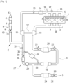
- a motorization device which comprises an internal combustion engine 1, for example of the spark ignition type (operating in particular on gasoline), which is presented here in the form of a four-cylinder engine online. It is an engine 1 which is supercharged by a turbocharger, and which is provided with a low pressure partial recirculation circuit of the exhaust gases (EGR-LP circuit).
- EGR-LP circuit low pressure partial recirculation circuit of the exhaust gases
- the engine 1 is associated with an air intake circuit 2 and an exhaust circuit 3 for the engine's combustion gases. It is also associated with a fuel supply circuit of which the injectors 4 have been shown which supply the different cylinders of the engine with fuel (petrol), for example from a common rail 5.
- fuel for example from a common rail 5.
- the intake circuit 2 comprises, from upstream to downstream in the direction of air circulation from the location marked by the arrow E in the figure: an air filter 6; a flow meter 7 capable of measuring a mass flow rate of air Qair entering the engine; an air intake valve 8, with a first upstream pressure sensor 9 capable of measuring the pressure at the inlet of said valve 8 and a first downstream pressure sensor 10 capable of measuring the pressure at the outlet of said valve 8; a compressor 11 of turbocharger 12; a gas admission valve 13 in the engine, or throttle body 13; an intake gas cooler 14; and, an air distributor 15, or intake manifold 15, provided with a pressure sensor 16 and a temperature sensor 17, which are respectively capable of measuring the value of the pressure Pcol and the value of the temperature Tcol of the gases in the distributor 15.
- the exhaust circuit 3 includes, from upstream to downstream in the direction of circulation of the combustion gases and until their evacuation after post-treatment in the external atmosphere at the location marked by the arrow S in the figure: an exhaust manifold 18; a turbine 19 of the turbocharger 12, mounted on a shaft common to the compressor 11; and a plurality of devices for post-treatment, or depollution, of the combustion gases emitted by the engine 1.
- the turbine 19 serves in a manner known per se to take energy from the exhaust gases (combustion gases) which pass through it by expanding them, and to transfer this energy to the compressor 11 via their common shaft in order to to compress the intake gases.
- the turbine can be of the “variable geometry” type, that is to say include a turbine wheel with vanes of variable inclination, the degree of inclination of which is adjusted to regulate the quantity of energy taken. to the passing gases and the pressure to which the intake gases are compressed (boost pressure).
- the exhaust circuit includes a turbine bypass circuit, equipped with an exhaust discharge valve (well known as a “waste gate” valve according to its name in English). The quantity of energy taken from the exhaust gas is then adjusted by adjusting the flow of exhaust gas passing through the turbine, by opening the discharge valve to a greater or lesser extent.
- the exhaust circuit 3 comprises a first depollution device 20 which is presented here, in the case of a gasoline engine, in the form of a first three-way catalyst 20, for example a close catalyst mounted in the engine compartment of the vehicle, with an upstream oxygen probe 21 of the proportional type capable of measuring a richness value R of the exhaust gases at the inlet of said first catalyst 20, and with furthermore a downstream oxygen probe 22 which can be of the type binary to determine a rich or lean state of the exhaust gases at the outlet of said first catalyst 20, or alternatively, of proportional type to measure a value of the richness of the exhaust gases at the outlet of said first catalyst 20.
- a first depollution device 20 which is presented here, in the case of a gasoline engine, in the form of a first three-way catalyst 20, for example a close catalyst mounted in the engine compartment of the vehicle, with an upstream oxygen probe 21 of the proportional type capable of measuring a richness value R of the exhaust gases at the inlet of said first catalyst 20, and with furthermore a downstream oxygen probe 22 which
- the upstream oxygen sensor 21 alone, or the upstream oxygen sensor 21 associated with the downstream oxygen sensor 22, serves to adjust the proportions of the air - fuel mixture in the engine cylinders for the production of desired engine torque.
- it can be a closed loop adjustment of the richness R of the mixture to a set richness value Rsp equal to 1.
- the signal delivered by the upstream oxygen probe 21 makes it possible to determine the current value of the richness R upstream of the first catalyst 20; the difference between said richness value R and the setpoint Rsp (equal to 1) is entered into a regulator, the output of which is a fuel flow correction value Qcarb,corr which is added to a fuel flow setpoint Qcarb ,sp,bo calculated in open loop from an estimated air flow value in stoichiometric proportions (1 gram of fuel for 14.7 grams of air).
- a regulator the output of which is a fuel flow correction value Qcarb,corr which is added to a fuel flow setpoint Qcarb ,sp,bo calculated in open loop from an estimated air flow value in stoichiometric proportions (1 gram of fuel for 14.7 grams of air).
- it can be a closed loop adjustment of the richness of the mixture R on a set value Rsp which is equal to 1 plus a positive or negative correction value which depends on the indications of the probe at downstream oxygen 22.
- the exhaust circuit 3 includes a second pollution control device 23; here a particle filter 23, and a third pollution control device 24, for example a second three-way catalyst 24 which is mounted under the body of the vehicle.
- the exhaust circuit 3 also includes an exhaust pipe 25 which can be provided with an exhaust valve 26.
- the exhaust circuit 3 comprises a low pressure partial recirculation circuit 27 of the exhaust gases at the intake.
- This EGR-BP circuit 27 takes part of the exhaust gases at a point of the exhaust circuit 3 where they are already expanded by the turbine 19, in the example of the figure downstream of the particle filter 23. It reintroduces these gases at a point of the intake circuit 2 where the intake gases are not further compressed by the compressor 11, on the example of the figure between the air intake valve 8 and the compressor 11.
- the EGR-BP circuit 27 includes a recycled gas cooler 28; a recycled gas filter 29; a recycled gas adjustment valve 30, also called EGR-BP valve 30; and, a device for measuring the differential pressure Pdiff, egrbp prevailing at the terminals of the EGR-BP circuit 27 comprising a differential pressure sensor 32 connected to two upstream 33 and downstream 34 taps of the exhaust circuit, at the ends of the EGR- circuit BP 27.
- the engine can also have other specific features without departing from the scope of the invention.
- it may include a variable intake distribution system (also known as “VVT” according to the English acronym for: Variable Valve Timing), capable of varying the timing of the intake valves in the combustion cycle of the engine. .
- VVT variable intake distribution system
- the method of adjusting the engine 1 is for example consistent with the following description, when the engine is mounted on a motor vehicle:
- An engine torque setpoint C coming from a value of depression of the vehicle's accelerator pedal by the driver, is transformed by a computer (not shown) of the engine, according to the engine speed N, into a setpoint of air flow Qair,sp, a richness setpoint which can be equal to 1 (or alternatively a corrected value), and a recycled gas rate setpoint ⁇ egr,sp, also called EGR rate setpoint.
- the computer calculates a recycled gas flow setpoint Qegrbp,sp, and a total flow setpoint Qmot,sp to be admitted into the engine cylinders, according to the following equations:
- the volumetric efficiency ⁇ is a quantity which depends at least on the engine speed N and the pressure prevailing in the collector Pcol. It may depend on additional parameters such as for example the position of the variable valve timing system on the intake (WT on the intake) if the engine is equipped with it.
- the volumetric efficiency ⁇ is mapped by preliminary tests carried out on an instrumented test bench by varying the different parameters concerned (speed N, pressure in the collector Pcol, etc.), then the map is stored in a memory of the engine computer .
- the total intake gas flow setpoint Qmot,sp is transformed into an intake manifold pressure flow setpoint Pcol,sp (which depends on the temperature Tcol and can vary even if the flow setpoint does not vary).
- the flow rate in the intake manifold Pcol is then adjusted to said pressure setpoint Pcol, sp in a closed loop, by adjusting the angular position of the throttle body 13 when the engine is operating in the atmospheric domain.
- the pressure is regulated by a combination of adjustments of the angular position of the throttle body 13 and the angular position of the blades of the turbine 19 (or alternatively: the position of the “waste gate” valve).
- the current value of the pressure Pcol is determined by the pressure sensor of the intake manifold 16 and the value of the pressure setpoint Pcol, sp is determined using the equation of the filling model, from the mapped volumetric efficiency ⁇ and the temperature value in the intake manifold Tcol which is measured by the temperature sensor 17 of the intake manifold.
- the flow rate of the recycled gases Qegr is adjusted in a closed loop to its setpoint value Qegrbp,sp, which is defined according to the equation mentioned above, generally by adjusting the angular position of the EGR-BP 30 valve. In certain cases, it may be necessary to reduce the opening of the air intake valve 8 so as to create downstream, and therefore at the outlet of the EGR-BP circuit 27, a depression likely to increase the circulation of the recycled gases .
- the current value of the recycled gas flow rate Qegrbp is calculated as the difference between the total intake gas flow rate Qmot (by application of the filling model equation) and the current air flow rate.
- fresh Qair which is determined by the flow meter 7.
- Q HFM The value of the air flow Qair measured by the flow meter 7 is denoted Q HFM in the following (HFM designates the acronym in English for “Hot Flow Meter” which designates a wire flow meter hot).
- the richness R is adjusted in a closed loop around its setpoint Rsp (for example 1) by adjusting the fuel flow, as explained above.
- Rsp for example 1
- a method for diagnosing such a flow meter is known from the state of the art in which, at a stabilized operating point of the engine, the recirculation of the exhaust gases at the intake is eliminated, so that only air is introduced into the engine's combustion chambers.
- the invention aims to remedy the defects of known diagnostic methods, by proposing a reliable diagnostic method, limiting the risks of non-detection and false detection, and not requiring modifying the usual operation of the engine by intrusive adjustments resulting in an increase in fuel consumption or polluting emissions from the engine.
- the engine 1 is here for example of the diesel type, with four cylinders in line, supercharged by turbocharger, equipped with a low pressure partial recirculation circuit 27 of the exhaust gases at the intake, and it also has, in the example shown, a high pressure partial recirculation circuit 37 of the exhaust gases at the intake (also known as: EGR-HP circuit), provided with an adjustment valve 38, called the EGR-HP valve 38.
- a high pressure partial recirculation circuit 37 of the exhaust gases at the intake also known as: EGR-HP circuit
- EGR-HP valve 38 an adjustment valve 38
- This circuit 37 takes part of the exhaust gases at a point of the exhaust circuit 3 located before the turbine 19. Its other end opens downstream of the gas admission valve 13, which is mounted downstream of the compressed gas cooler 14.
- the flow rate of the recycled gases at high pressure is regulated by the degree of opening of the EGR-HP valve 38.
- the intake valve 13 is associated with an upstream pressure sensor 35 and a downstream pressure sensor 36.
- the EGR-HP valve 38 is also associated with an upstream 39 and downstream 40 pressure sensor. The two valves are still each associated with a downstream temperature sensor (not shown on the figure 2 ).
- the pollution control devices 20,23,24, for a diesel engine can be presented as follows:
- the first depollution device 20 is for example an oxidation catalyst. It may also include a nitrogen oxide trap. He is associated with an upstream oxygen probe 21, but it is generally without a downstream oxygen probe.
- the upstream oxygen sensor 21 is generally not used to adjust the richness R of the air-fuel mixture in a closed loop to a set value Rsp when the engine is in a usual mixture operating mode. poor, but for monitoring and diagnostic purposes, Qcarb fuel flow being injected in open loop. In other words, the fuel flow is adjusted in open loop to a flow setpoint value Qcarb,sp,bo which is calculated to correspond to the setpoint torque Csp.
- the probe 21 can be used to adjust said richness R in a closed loop in particular operating modes of the engine such as a mode of regenerating the nitrogen oxide trap in a rich mixture.
- the second depollution device 23 may comprise a catalyst for the selective reduction of nitrogen oxides, also called an SCR catalyst (from the English acronym for: Selective Catalytic Reduction), for example a catalyst also having the function of a particle filter , and an oxidation catalyst.
- SCR catalyst from the English acronym for: Selective Catalytic Reduction
- the third depollution device 24 can be, for example, a second SCR catalyst.
- the engine setting differs from the engine setting shown on the figure 1 in that this example is a diesel engine and there is an additional recirculation circuit, more precisely a high pressure recirculation circuit 37.
- the diesel engine of the figure 2 could have only one low pressure recirculation circuit; in the same way, the gasoline engine of the figure 1 could include a low pressure recirculation circuit and a high pressure recirculation circuit.
- the engine torque setpoint Csp coming from a value of depression of the vehicle's accelerator pedal by the driver, is transformed by a computer (not shown) of the engine, according to the engine speed N, into a setpoint of air flow Qair,sp, a fuel flow setpoint Qcarb,sp,bo which corresponds to a theoretical richness setpoint value Rsp, and an EGR rate setpoint ⁇ egr,sp.
- the computer calculates a recycled gas flow setpoint Qegr,sp and a total flow setpoint Qmot,sp to be admitted into the engine cylinders, according to the following equations:
- the recycled gas flow setpoint Qegr,sp is divided into a gas flow setpoint Qegrhp,sp to be provided by the EGR-HP circuit and a gas flow setpoint Qegrbp,sp to be provided by the circuit EGR-BP, according to specific constraints. For example, to avoid the risk of blocking the EGR-LP valve when cold, it is common to use only high pressure recycled gases.
- the flow rate in the intake manifold Pcol is adjusted to said pressure setpoint Pcol, sp in a closed loop, by adjusting the angular position of the fins of the turbine 19 (or alternatively: the position of the “waste gate” valve), but generally without changing the position of the inlet valve.
- the flow rate of the recycled gases at high pressure Qegrhp is adjusted in a closed loop to its setpoint value Qegrhp,sp, generally by adjusting the angular position of the EGR-HP valve 38.
- the flow rate of the exhaust gases recycled at low pressure Qegrbp is adjusted in a closed loop to its setpoint value Qegrbp, sp generally by adjusting the position of the EGR-BP 30 valve.
- the current flow rate of recycled gases at low pressure Qegrbp is calculated as equal to the value of the total flow rate Qmot (from the filling model), from which the air flow value which is measured by the flow meter Q HFM is subtracted, and from which we further subtract the flow rate of recycled gases at high pressure Qegrhp calculated from the Barré Saint Venant equation.
- the fuel flow Qcarb for a diesel engine, is injected in an open loop to match the target fuel flow Qcarb,sp,bo.
- this target fuel flow Qcarb,sp,bo is calculated as the product of the target air flow Qair,sp multiplied by a theoretical value of target richness to obtain Rsp, which is then divided by 14.7 .
- the upstream oxygen probe 21 is not used to adjust the richness in a closed loop around the theoretical setpoint value Rsp, but to monitor to what extent this setpoint is reached as part of the adjustment of the fuel flow Qcarb in an open loop on its Qcarb,sp,bo deposit.
- FIG. 3 represents the different stages of an embodiment of the diagnostic method according to the invention, which is suitable for a motor with gasoline or a diesel engine provided with at least one EGR-LP circuit and which may also include an EGR-HP circuit.
- the principle of diagnosis according to the invention consists, in the event of a need to diagnose the flow meter 7, which is for example dictated by the on-board diagnostic standards (OBD standards for: On Board Diagnosis), to initially proceed to at least a known pre-diagnosis which is not intrusive, that is to say which does not disturb the operation of the engine and in particular which does not increase its fuel consumption (in the case of a petrol engine) or its polluting emissions (in the case of a diesel engine), and secondly to only carry out the diagnosis of the state of the art in which the recirculation of exhaust gases is cut off at a stabilized operating point only when the pre-diagnosis does not allow us to conclude whether the flow meter is in good condition or faulty.
- OBD on Board Diagnosis
- the method comprises a step 100 which may consist of carrying out one or more subsequent pre-diagnoses of the flow meter.
- These diagnostics are based on the comparison, with two distinct thresholds, of a criterion representative of the difference between a real air flow and the air flow measured by the Q HFM flow meter, said pre-diagnosis not making it possible to conclude when said criterion is between said two thresholds.
- real flow in the sense of this invention is meant a flow value Qair, or a value of a criterion representative of the air flow, which is assumed to be true to the extent that it is measured by means which do not depend on the flow meter and which are assumed to be perfect.
- the criterion is equal to the absolute value of the difference between the air flow measured by the Q HFM flow meter and a Qair flow value calculated from a filling model of the cylinders of the engine and/or Barré Saint Venant models to the valve terminals of the air intake circuit and the engine exhaust circuit.
- this is the absolute value of a fuel flow correction Qcarb,corr applied to adjust in closed loop the value of the richness of the air-fuel mixture R to a set value .
- the current richness value being measured by the upstream oxygen probe 21 of the first depollution device 20 in the context of closed loop regulation, it is a function of the actual air flow, for a given fuel flow. Consequently, a difference between the actual air flow Qair and the air flow measured Q HFM by the flow meter results in a different measurement of the oxygen probe 21, and in a modified correction of the fuel flow Qcarb,corr to be applied as part of closed loop R wealth regulation.
- This embodiment is especially applicable in the case of a gasoline engine, in which such closed-loop adjustment of the richness R is carried out. However, it does not exclude the case of a diesel engine, in which such closed loop adjustment of the richness R is sometimes applied in certain particular circumstances (regeneration of a nitrogen oxide trap in a rich mixture for example) .
- this is the absolute value of the difference between a real richness value R and a theoretical richness setpoint value Rsp corresponding to a fuel flow Qcarb, sp, bo injected in open loop.
- the real richness value R being measured from the indications of the upstream oxygen probe 21, it is a function of the real air flow Qair.
- the target fuel flow Qcarb,sp,bo is calculated from the target air flow Qair,sp which is theoretical and which may not be achieved.
- a first possible pre-diagnosis consists of comparing a first value of the air flow Q HFM measured by the flow meter 7 with a second value of the air flow Qair calculated as the difference between on the one hand, the total flow of gases d the admission Qmot calculated from the filling model, and on the other hand, the sum of the flow rate of the gases recycled at high pressure Qegrhp and the flow rate of the gases recycled at low pressure Qegrbp which are each calculated by Barré Saint Venant models.
- the flow meter is declared in good condition if the absolute value of the difference between the two values is less than a first threshold, and it is declared faulty if the absolute value of the difference is greater than a second threshold which is strictly greater than the first threshold . Due to the imprecision in the different measurements and the different models used in this pre-diagnosis, there is an area between the two thresholds where the pre-diagnosis presents uncertainty and where we cannot conclude.
- a second pre-diagnosis consists of taking advantage of a driving phase where, the driver releasing his foot from the accelerator pedal, the engine torque setpoint Csp becomes zero and the fuel injection is cut off. If there is a need to diagnose the flow meter, the EGR valve(s) present on the engine are closed, which does not create any problem of excess fuel consumption or polluting emissions, as combustion is stopped. The engine then only receives air. A first air flow value measured by the flow meter Q HFM is compared with the total intake flow value Qmot, in fact air, calculated by the filling model.
- the flow meter is declared in good condition if the absolute value of the difference between the two values is less than a third threshold, and it is declared faulty if the absolute value of the difference is greater than a fourth threshold which is strictly greater than the third threshold .
- a third threshold if the absolute value of the difference is less than a third threshold.
- a fourth threshold which is strictly greater than the third threshold.
- a third pre-diagnosis usable in the case of a diesel engine, can be carried out during a regeneration phase of a particle filter, or during a purging phase of a nitrogen oxide trap (so-called “purge” deNOx” in which the trap of nitrogen oxide molecules stored in a lean mixture is emptied, or so-called “deSOx” purge in which the sulfur oxide molecules which have accumulated there are eliminated).
- the flow meter is declared in good condition if the absolute value of the difference between the two values is less than a fifth threshold, and it is declared faulty if the absolute value of the difference is greater than a sixth threshold which is strictly greater than the fifth threshold.
- a fifth threshold if the absolute value of the difference between the two values is less than a fifth threshold
- a sixth threshold which is strictly greater than the fifth threshold.
- a fourth pre-diagnosis consists of monitoring the evolution of the quantity of fuel injected Qcarb for adjusting the richness value R in a closed loop, during a change in the engine torque setpoint.
- the total flow rate of injected fuel Qcarb is the sum of a first flow rate Qcarb,sp,bo calculated as the quantity necessary to achieve the combustion of the fuel with the planned target air flow rate Qair,sp in the engine at the richness of planned setpoint Rsp, and a correction flow rate Qcarb,corr to adjust said richness value R to the setpoint Rsp.
- the first fuel flow calculated thus in open loop Qcarb,sp,bo is equal to the setpoint air flow Qair,sp divided by 14.7.
- the first fuel flow Qcarb,sp,bo constitutes a pre-positioning value for the opening duration of the injectors, which then allows rapid convergence of the closed adjustment loop and with a positive or negative flow correction value which remains low, within known predetermined limits.
- the EGR-LP gas flow is set to a value which is too high, so that the target air flow which was planned Qair,sp does not is not achieved in reality.
- the actual air flow Qair being too low, the upstream oxygen probe 21 indicates richness values R which are also lower, which results in a positive flow correction value Qcarb, fuel corr which goes outside the limits known predetermined.
- the negative fuel flow correction value Qcarb,corr will also be too high (in absolute value) and will exceed the known predetermined limits.
- a fifth pre-diagnosis consists of monitoring the value of the richness R measured by the upstream oxygen probe 21 as part of the open loop adjustment of the fuel flow Qcarb to its setpoint Qcarb,sp,bo.
- the EGR-LP gas flow is set to a value that is too high, so that the air flow of target which was planned Qair,sp is not achieved in reality.
- the upstream oxygen probe 21 indicates a richness value R which is higher than the theoretical setpoint value Rsp which was used to calculate the setpoint fuel flow Qcarb,sp,bo.
- the richness value R is noted.
- the flow meter is declared in good condition if the absolute value of the difference between this value R and the theoretical richness value of reference Rsp corresponding to the quantity of fuel Qcarb, sp, bo injected in an open loop to obtain the target torque Csp is less than a ninth threshold, and it is declared faulty if said absolute value is greater than a tenth threshold which is strictly greater than the ninth threshold. There remains doubt when the absolute value is between said two thresholds.
- test step 200 in which it is checked whether there is any doubt about the failure of the flow meter.
- the method directs towards a step 300 in which the numerator of an IUPR index (English acronym for “In Use Performance Ratio”) is incremented by 1 within the framework of on-board diagnostic standards .
- an alert can be issued. raised to the dashboard of the vehicle in the form of the lighting of a warning light, so that the vehicle can be repaired.
- step 400 the process continues at step 400 in which the recirculation of the exhaust gases is cut off. Then we completely close the EGR-BP 30 valve and also, if necessary, the EGR-HP 38 valve.
- step 500 in which the main diagnosis itself is carried out. It includes, as explained above, a step of measuring a first value of the air flow using the flow meter; a step of calculating a second value of the air flow using the filling model, from the pressure Pcoll and the temperature Tcoll measured in the intake manifold; a step of comparing the absolute value of the difference between said measured value and said calculated value with a threshold; and, a step in which the flow meter is declared in good condition or faulty, respectively depending on whether said absolute value is lower or higher than said threshold.
- the method can also include a step similar to step 300 of incrementing the IUPR index and a step of reporting the fault to the dashboard in the case where the flow meter is non-compliant.
- the method according to the invention makes it possible to limit the occurrences of the very reliable but intrusive main diagnosis, by replacing it with a pre-diagnosis which does not degrade the behavior of the engine in most cases where such a pre-diagnosis does not. presents no doubt about the conclusion.
- the multiplication of pre-diagnoses makes it possible to further reduce these occurrences.
Landscapes
- Engineering & Computer Science (AREA)
- Chemical & Material Sciences (AREA)
- Combustion & Propulsion (AREA)
- Mechanical Engineering (AREA)
- General Engineering & Computer Science (AREA)
- Analytical Chemistry (AREA)
- Physics & Mathematics (AREA)
- Fluid Mechanics (AREA)
- Output Control And Ontrol Of Special Type Engine (AREA)
- Exhaust-Gas Circulating Devices (AREA)
- Testing Of Engines (AREA)
- Combined Controls Of Internal Combustion Engines (AREA)
Claims (10)
- Verfahren zur Diagnose eines Luftdurchflussmessers (7) in einem aufgeladenen Verbrennungsmotor (1), der mindestens einen Kreislauf (27) zur Niederdruck-Teilrückführung (27) der Abgase zur Ansaugseite des Motors aufweist, und außerdem einen Kreislauf (37) zur Hochdruck-Teilrückführung der Abgase zur Ansaugseite des Motors aufweisen kann, wobei das Verfahren mindestens einen Schritt (400) der Abschaltung der Abgas-Rückführung und dann einen Schritt der Hauptdiagnose (500) enthält, in der: ein erster Wert des in den Motor angesaugten Luftdurchflusses (QHFM) vom Durchflussmesser (7) gemessen wird; ein zweiter Wert des Luftdurchflusses (Qair) dank eines Füllmodells der Zylinder des Motors berechnet wird; und gefolgert wird, dass der Durchflussmesser in gutem Zustand bzw. defekt ist, wenn der Absolutwert der Abweichung zwischen dem ersten und dem zweiten Wert niedriger oder höher ist als eine Schwelle,
wobei das Verfahren dadurch gekennzeichnet ist, dass- das Verfahren vor der Abschaltung der Abgas-Rückführung einen Schritt (100) aufweist, in dem mindestens eine Vordiagnose des Durchflussmessers (Z) durchgeführt wird, wobei ein für die Abweichung zwischen dem realen Luftdurchfluss (Qair) und dem vom Durchflussmesser gemessenen Luftdurchfluss (QHFM) repräsentatives Kriterium mit zwei Schwellen verglichen wird, wobei die Vordiagnose es ermöglicht, zu folgern, dass der Durchflussmesser in gutem Zustand ist, wenn die Abweichung niedriger ist als die kleinste der zwei Schwellen, und dass er defekt ist, wenn die Abweichung höher ist als die größte der zwei Schwellen, wobei die Vordiagnose keine Folgerung ermöglicht, wenn die Abweichung zwischen den zwei Schwellen liegt;- der Schritt der Abschaltung der Abgas-Rückführung (400) und der Schritt der Hauptdiagnose (500) nur durchgeführt werden, wenn die Vordiagnose (100) keine Folgerung erlaubt. - Verfahren nach Anspruch 1, wobei das für die Abweichung zwischen dem realen Luftdurchfluss (Qair) und dem vom Durchflussmesser gemessenen Luftdurchfluss (QHFM) repräsentative Kriterium gleich dem Absolutwert der Differenz zwischen einem ersten vom Durchflussmesser gemessenen Luftdurchflusswert und einem ausgehend von einem Füllmodell der Zylinder des Motors und/oder von Barré-Saint-Venant-Modellen an den Anschlüssen von Ventilen (13, 30, 38) des Luftansaugkreislaufs und/oder des Abgaskreislaufs des Motors berechneten zweiten Luftdurchflusswert ist.
- Verfahren nach Anspruch 1, wobei das für die Abweichung zwischen dem realen Luftdurchfluss (Qair) und dem vom Durchflussmesser gemessenen Luftdurchfluss (QHFM) repräsentative Kriterium gleich dem Absolutwert einer Treibstoffmengenkorrektur (Qcarb,corr) ist, die angewendet wird, um in geschlossenem Regelkreis die Anreicherung des Luft-Treibstoff-Gemischs (R) im Motor um einen Sollwert (Rsp) herum einzustellen.
- Verfahren nach Anspruch 1, wobei das für die Abweichung zwischen dem realen Luftdurchfluss (Qair) und dem vom Durchflussmesser gemessenen Luftdurchfluss (QHFM) repräsentative Kriterium gleich dem Absolutwert der Differenz zwischen einem von einer einer Abgasentgiftungsvorrichtung (20) des Motors vorgelagert montierten Sauerstoffsonde (21) gemessenen ersten Anreicherungswert (R) und einem theoretischen Anreicherungssollwert (Rsp) ist, der einer Treibstoffmenge entspricht, die in offenem Regelkreis (Qcarb,sp,bo) in den Motor injiziert wird.
- Verfahren nach einem der Ansprüche 1 oder 2, dadurch gekennzeichnet, dass der Vordiagnoseschritt (100) mindestens eine der folgenden Vordiagnosen enthält:- eine erste Vordiagnose, wobei: ein erster Wert des Luftdurchflusses (QHFM) vom Durchflussmesser (7) gemessen wird; ein zweiter Wert des Luftdurchflusses (Qair) als die Differenz zwischen einerseits dem Gesamtdurchfluss der Ansauggase (Qmot) im Motor, der ausgehend von einem Füllmodell berechnet wird, und andererseits dem rückgeführten Gasdurchfluss berechnet wird, der ausgehend von Barré-Saint-Venant-Modellen an den Anschlüssen der Einstellventile (30, 38) des oder der Rückführungskreisläufe berechnet wird; der Absolutwert der Abweichung zwischen dem gemessenen Wert (QHFM) und dem berechneten Wert des Luftdurchflusses (Qair) berechnet wird; der Durchflussmesser als in gutem Zustand erklärt wird, wenn der Absolutwert niedriger ist als eine erste Schwelle; der Durchflussmesser als defekt erklärt wird, wenn der Absolutwert höher ist als eine zweite Schwelle, die strikt höher ist als die erste Schwelle; und nicht gefolgert werden kann, wenn der Absolutwert zwischen der ersten Schwelle und der zweiten Schwelle liegt,- eine zweite Vordiagnose, wobei: der Drehmomentsollwert (Csp) null ist; die Treibstoffzufuhr abgeschaltet ist; die Abgasrückführung abgeschaltet ist; ein erster Luftdurchflusswert (QHFM) vom Durchflussmesser gemessen wird; ein zweiter Wert des Luftdurchflusses (Qair) als der von einem Füllmodell berechnete Gesamtdurchfluss der Gasansaugung in den Motor (Qmot) bestimmt wird; der Absolutwert der Differenz zwischen dem gemessenen Wert und dem berechneten Wert berechnet wird; der Durchflussmesser als in gutem Zustand erklärt wird, wenn der Absolutwert niedriger ist als eine dritte Schwelle; der Durchflussmesser als defekt erklärt wird, wenn der Absolutwert höher ist als eine vierte Schwelle, die strikt höher ist als die dritte Schwelle; und nicht gefolgert werden kann, wenn der Absolutwert zwischen der dritten Schwelle und der vierten Schwelle liegt,- eine dritte Vordiagnose, wobei der Motor (1) ein Dieselmotor ist, wobei: eine Abgasentgiftungsvorrichtung (20, 23) des Motors gereinigt oder regeneriert wird, indem ein Ansaugventil der Gase (13) des Motors teilweise wieder geschlossen wird und indem der Niederdruck-Rückführungskreislauf (37) vollständig geschlossen wird; ein erster Wert des Luftdurchflusses (QHFM) vom Durchflussmesser gemessen wird; ein von einem Barré-Saint-Venant-Modell bestimmter zweiter Wert des Luftdurchflusses an den Anschlüssen des Ansaugventils (13) berechnet wird; der Absolutwert der Abweichung zwischen dem gemessenen Wert und dem berechneten Wert berechnet wird; der Durchflussmesser als in gutem Zustand erklärt wird, wenn der Absolutwert niedriger ist als eine fünfte Schwelle; der Durchflussmesser als defekt erklärt wird, wenn der Absolutwert höher ist als eine sechste Schwelle, die strikt höher ist als die fünfte Schwelle; und nicht gefolgert werden kann, wenn der Absolutwert zwischen der fünften Schwelle und der sechsten Schwelle liegt.
- Verfahren nach einem der Ansprüche 1 oder 3, dadurch gekennzeichnet, dass es mindestens eine vierte Vordiagnose enthält, wobei: da die Anreicherung des Luft-Treibstoff-Gemischs (R) im Motor in geschlossenem Regelkreis auf einen Sollwert (Rsp) eingestellt ist: der Wert einer Treibstoffdurchflusskorrektur (Qcarb,corr) gemessen wird, der zu einem in offenem Regelkreis (Qcarb,sp,bo) ausgehend vom in den Motor anzusaugenden Sollluftdurchfluss (Qair,sp) bestimmten ersten Treibstoffdurchflusswert hinzuzufügen ist; der Absolutwert der Korrektur (Qcarb,corr) berechnet wird, wenn der Anreicherungsregelkreis zum Anreicherungsollwert konvergiert ist; der Durchflussmesser als in gutem Zustand erklärt wird, wenn der Absolutwert niedriger ist als eine siebte Schwelle; der Durchflussmesser als defekt erklärt wird, wenn der Absolutwert höher ist als eine achte Schwelle, die strikt höher ist als die siebte Schwelle; und nicht gefolgert werden kann, wenn der Absolutwert zwischen der siebten und der achten Schwelle liegt.
- Verfahren nach einem der Ansprüche 1 oder 4, dadurch gekennzeichnet, dass es mindestens eine fünfte Vordiagnose enthält, wobei, da der Treibstoffdurchfluss (Qcarb) in offenem Regelkreis auf einen Sollwert (Qcarb,sp,bo) eingestellt ist, der dem Erreichen eines theoretischen Anreicherungssollwerts (Rsp) für einen Sollluftdurchfluss (Qair,sp) im Motor entspricht: ein Wert der Anreicherung (R) im Motor von einer einer Abgasentgiftungsvorrichtung (20) des Motors vorgelagert montierten Sauerstoffsonde (21) gemessen wird; der Absolutwert der Abweichung zwischen dem gemessenen Wert (R) der Anreicherung und dem theoretischen Sollwert (Rsp) berechnet wird; der Durchflussmesser als in gutem Zustand erklärt wird, wenn der Absolutwert niedriger ist als eine neunte Schwelle; der Durchflussmesser als defekt erklärt wird, wenn der Absolutwert höher ist als eine zehnte Schwelle, die strikt höher ist als die neunte Schwelle; und nicht gefolgert werden kann, wenn der Absolutwert zwischen der neunten und der zehnten Schwelle liegt.
- Verfahren nach einem der vorhergehenden Ansprüche, wobei das Füllmodell eine Gleichung ist, die den Wert des in den Motor eintretenden Ansauggasdurchflusses (Qmot) abhängig von einem Druckwert (Pcol) in einem Ansaugkrümmer des Motors, einem Temperaturwert (Tcol) im Krümmer und einem volumetrischen Leistungswert (η) bestimmt, der eine Funktion einer Einheit von Parametern ist, die mindestens die Drehzahl des Motors (N) und den Druck im Ansaugkrümmer (Pcol) enthält.
- Verfahren nach einem der vorhergehenden Ansprüche, wobei der Gesamtdurchfluss der Ansauggase in den Motor (Qmot) eingestellt wird, indem der Druck im Ansaugkrümmer (Pcol) um einen Sollwert herum eingestellt wird, indem die Position eines Luftansaugventils (13) des Motors angepasst wird.
- Verfahren nach einem der vorhergehenden Ansprüche, wobei der Durchfluss von rückgeführten Niederdruck-Abgasen (Qegrbp) in geschlossenem Regelkreis auf einen Sollwert eingestellt wird, indem die Position eines Niederdruck-Rückführungsventils (30) des Motors angepasst wird.
Applications Claiming Priority (1)
| Application Number | Priority Date | Filing Date | Title |
|---|---|---|---|
| FR2010965A FR3115566B1 (fr) | 2020-10-26 | 2020-10-26 | Procédé de diagnostic d’un débitmètre d’air pour moteur à combustion interne. |
Publications (2)
| Publication Number | Publication Date |
|---|---|
| EP3995685A1 EP3995685A1 (de) | 2022-05-11 |
| EP3995685B1 true EP3995685B1 (de) | 2023-11-29 |
Family
ID=73699138
Family Applications (1)
| Application Number | Title | Priority Date | Filing Date |
|---|---|---|---|
| EP21204628.8A Active EP3995685B1 (de) | 2020-10-26 | 2021-10-26 | Verfahren zur diagnose eines luftdurchflussmessers für einen verbrennungsmotor |
Country Status (2)
| Country | Link |
|---|---|
| EP (1) | EP3995685B1 (de) |
| FR (1) | FR3115566B1 (de) |
Families Citing this family (1)
| Publication number | Priority date | Publication date | Assignee | Title |
|---|---|---|---|---|
| CN115638058A (zh) * | 2022-10-28 | 2023-01-24 | 联合汽车电子有限公司 | 车辆泄漏诊断控制方法、整车控制器、车辆和存储介质 |
Family Cites Families (4)
| Publication number | Priority date | Publication date | Assignee | Title |
|---|---|---|---|---|
| JP2004100517A (ja) * | 2002-09-06 | 2004-04-02 | Mitsubishi Fuso Truck & Bus Corp | 内燃機関の故障検出装置 |
| JP5120333B2 (ja) * | 2009-05-07 | 2013-01-16 | 株式会社デンソー | エアフロメータの故障診断装置 |
| DE102010044164B4 (de) * | 2010-11-19 | 2022-07-14 | Robert Bosch Gmbh | Verfahren und Vorrichtung zur Steuerung einer Brennkraftmaschine |
| DE102016220029A1 (de) * | 2016-10-14 | 2018-04-19 | Robert Bosch Gmbh | Verfahren und Vorrichtung zur Überwachung eines Luftmassensensors einer Brennkraftmaschine mit Abgasrückführung |
-
2020
- 2020-10-26 FR FR2010965A patent/FR3115566B1/fr active Active
-
2021
- 2021-10-26 EP EP21204628.8A patent/EP3995685B1/de active Active
Also Published As
| Publication number | Publication date |
|---|---|
| FR3115566B1 (fr) | 2022-09-09 |
| EP3995685A1 (de) | 2022-05-11 |
| FR3115566A1 (fr) | 2022-04-29 |
Similar Documents
| Publication | Publication Date | Title |
|---|---|---|
| EP1815118B1 (de) | Vorrichtung und verfahren zur bestimmung der von einem dieselmotor eines kraftfahrzeuges ausgestossenen nox-menge und diagnose- sowie motorverwaltungssystem mit einer derartigen vorrichtung | |
| EP2935828B1 (de) | Diagnoseverfahren für aufgeladenen motor und zugehöriger motor | |
| FR2874236A1 (fr) | Procede et dispositif de gestion d'un moteur a combustion interne | |
| FR2919671A1 (fr) | Procede de diagnostic d'un moteur a combustion interne par analyse des gaz d'echappement et dispositif de mise en oeuvre. | |
| EP3995685B1 (de) | Verfahren zur diagnose eines luftdurchflussmessers für einen verbrennungsmotor | |
| EP2699778B1 (de) | Verfahren zur fehlerdiagnose eines aufgeladenen motors und aufgeladener motor | |
| EP3387230B1 (de) | Verfahren zur diagnose eines katalysators zur selektiven reduktion von stickoxiden eines motors und zugehörige vorrichtung | |
| FR2877695A1 (fr) | Procede de gestion d'un moteur a combustion interne et dispositif pour sa mise en oeuvre | |
| FR3062418B1 (fr) | Procede de controle des emissions d'oxydes d'azote a l'echappement d'un moteur a combustion interne | |
| EP3234326B1 (de) | Diagnoseverfahren für ein abgasrückführsystem eines kraftfahrzeugmotors | |
| EP0599729B1 (de) | Verfahren zur Steuerung der Abgasrückführung bei einer Brennkraftmaschine | |
| EP4041998B1 (de) | Diagnoseverfahren für ein abgasnachbehandlungssystem eines fremdgezündeten verbrennungsmotors | |
| FR3118647A1 (fr) | Procédé de détection d’une fuite de gaz dans un circuit d’admission d’un dispositif de motorisation | |
| EP4166776B1 (de) | Verfahren zur diagnose der plausibilität eines luftdurchflussmessersensors in einer brennkraftmaschine | |
| FR2953564A3 (fr) | Procede et systeme de correction d'une mesure de debit d'air admis dans un moteur a combustion interne | |
| EP1630387A1 (de) | Verfahren zur Steuerung der Abgasrückführmenge in einer Brennkraftmaschine eines Kraftfahrzeuges | |
| FR2945321A3 (fr) | Procede de fonctionnement d'un dispositif de diagnostic de l'etat de capteurs de pression implantes dans un systeme d'admission d'un moteur a combustion interne suralimente | |
| EP3237732B1 (de) | Verfahren zur diagnose einer stickoxidfalle und zugehörige vorrichtung | |
| EP4031759A1 (de) | Verfahren zur einstellung der fettheit in einem verbrennungsmotor mit kontrollierter zündung | |
| EP4144982B1 (de) | Verfahren um kraftstoffdampfleck in einer brennkraftmaschine zu detektieren | |
| EP3816427B1 (de) | Verfahren zur diagnose eines gaslecks einer partiellen niederdruckabgasrückführung eines verbrennungsmotors | |
| EP4015808B1 (de) | Steuersystem und verfahren zur steuerung eines verbrennungsmotors, das auf dem wirkungsgrad der befüllung basiert | |
| EP4088012B1 (de) | Verfahren zur regeneration eines partikelfilters einer fremdgezündeten verbrennungskraftmaschine, und vorrichtung dafür | |
| EP2299094A1 (de) | Regelverfahren für einen aufgeladenen Dieselmotor mit Niederdruck-Abgasrückführung | |
| EP2844858A2 (de) | Verfahren zur abgasbehandlung eines druckbelasteten verbrennungsmotors mit abgasrückführung |
Legal Events
| Date | Code | Title | Description |
|---|---|---|---|
| PUAI | Public reference made under article 153(3) epc to a published international application that has entered the european phase |
Free format text: ORIGINAL CODE: 0009012 |
|
| STAA | Information on the status of an ep patent application or granted ep patent |
Free format text: STATUS: THE APPLICATION HAS BEEN PUBLISHED |
|
| AK | Designated contracting states |
Kind code of ref document: A1 Designated state(s): AL AT BE BG CH CY CZ DE DK EE ES FI FR GB GR HR HU IE IS IT LI LT LU LV MC MK MT NL NO PL PT RO RS SE SI SK SM TR |
|
| STAA | Information on the status of an ep patent application or granted ep patent |
Free format text: STATUS: REQUEST FOR EXAMINATION WAS MADE |
|
| 17P | Request for examination filed |
Effective date: 20220517 |
|
| RBV | Designated contracting states (corrected) |
Designated state(s): AL AT BE BG CH CY CZ DE DK EE ES FI FR GB GR HR HU IE IS IT LI LT LU LV MC MK MT NL NO PL PT RO RS SE SI SK SM TR |
|
| RAP3 | Party data changed (applicant data changed or rights of an application transferred) |
Owner name: RENAULT S.A.S |
|
| GRAP | Despatch of communication of intention to grant a patent |
Free format text: ORIGINAL CODE: EPIDOSNIGR1 |
|
| STAA | Information on the status of an ep patent application or granted ep patent |
Free format text: STATUS: GRANT OF PATENT IS INTENDED |
|
| RIC1 | Information provided on ipc code assigned before grant |
Ipc: F02M 26/05 20160101ALN20230515BHEP Ipc: F02M 26/06 20160101ALI20230515BHEP Ipc: F02D 41/18 20060101ALI20230515BHEP Ipc: F02D 41/22 20060101AFI20230515BHEP |
|
| RIC1 | Information provided on ipc code assigned before grant |
Ipc: F02M 26/05 20160101ALN20230525BHEP Ipc: F02M 26/06 20160101ALI20230525BHEP Ipc: F02D 41/18 20060101ALI20230525BHEP Ipc: F02D 41/22 20060101AFI20230525BHEP |
|
| INTG | Intention to grant announced |
Effective date: 20230612 |
|
| P01 | Opt-out of the competence of the unified patent court (upc) registered |
Effective date: 20230608 |
|
| GRAS | Grant fee paid |
Free format text: ORIGINAL CODE: EPIDOSNIGR3 |
|
| GRAA | (expected) grant |
Free format text: ORIGINAL CODE: 0009210 |
|
| STAA | Information on the status of an ep patent application or granted ep patent |
Free format text: STATUS: THE PATENT HAS BEEN GRANTED |
|
| AK | Designated contracting states |
Kind code of ref document: B1 Designated state(s): AL AT BE BG CH CY CZ DE DK EE ES FI FR GB GR HR HU IE IS IT LI LT LU LV MC MK MT NL NO PL PT RO RS SE SI SK SM TR |
|
| REG | Reference to a national code |
Ref country code: GB Ref legal event code: FG4D Free format text: NOT ENGLISH |
|
| REG | Reference to a national code |
Ref country code: CH Ref legal event code: EP |
|
| REG | Reference to a national code |
Ref country code: DE Ref legal event code: R096 Ref document number: 602021007273 Country of ref document: DE |
|
| REG | Reference to a national code |
Ref country code: IE Ref legal event code: FG4D Free format text: LANGUAGE OF EP DOCUMENT: FRENCH |
|
| RAP2 | Party data changed (patent owner data changed or rights of a patent transferred) |
Owner name: NEW H POWERTRAIN HOLDING, S.L.U. |
|
| REG | Reference to a national code |
Ref country code: LT Ref legal event code: MG9D |
|
| REG | Reference to a national code |
Ref country code: NL Ref legal event code: MP Effective date: 20231129 |
|
| PG25 | Lapsed in a contracting state [announced via postgrant information from national office to epo] |
Ref country code: GR Free format text: LAPSE BECAUSE OF FAILURE TO SUBMIT A TRANSLATION OF THE DESCRIPTION OR TO PAY THE FEE WITHIN THE PRESCRIBED TIME-LIMIT Effective date: 20240301 |
|
| PG25 | Lapsed in a contracting state [announced via postgrant information from national office to epo] |
Ref country code: IS Free format text: LAPSE BECAUSE OF FAILURE TO SUBMIT A TRANSLATION OF THE DESCRIPTION OR TO PAY THE FEE WITHIN THE PRESCRIBED TIME-LIMIT Effective date: 20240329 |
|
| PG25 | Lapsed in a contracting state [announced via postgrant information from national office to epo] |
Ref country code: LT Free format text: LAPSE BECAUSE OF FAILURE TO SUBMIT A TRANSLATION OF THE DESCRIPTION OR TO PAY THE FEE WITHIN THE PRESCRIBED TIME-LIMIT Effective date: 20231129 |
|
| PG25 | Lapsed in a contracting state [announced via postgrant information from national office to epo] |
Ref country code: ES Free format text: LAPSE BECAUSE OF FAILURE TO SUBMIT A TRANSLATION OF THE DESCRIPTION OR TO PAY THE FEE WITHIN THE PRESCRIBED TIME-LIMIT Effective date: 20231129 |
|
| PG25 | Lapsed in a contracting state [announced via postgrant information from national office to epo] |
Ref country code: LT Free format text: LAPSE BECAUSE OF FAILURE TO SUBMIT A TRANSLATION OF THE DESCRIPTION OR TO PAY THE FEE WITHIN THE PRESCRIBED TIME-LIMIT Effective date: 20231129 Ref country code: IS Free format text: LAPSE BECAUSE OF FAILURE TO SUBMIT A TRANSLATION OF THE DESCRIPTION OR TO PAY THE FEE WITHIN THE PRESCRIBED TIME-LIMIT Effective date: 20240329 Ref country code: GR Free format text: LAPSE BECAUSE OF FAILURE TO SUBMIT A TRANSLATION OF THE DESCRIPTION OR TO PAY THE FEE WITHIN THE PRESCRIBED TIME-LIMIT Effective date: 20240301 Ref country code: ES Free format text: LAPSE BECAUSE OF FAILURE TO SUBMIT A TRANSLATION OF THE DESCRIPTION OR TO PAY THE FEE WITHIN THE PRESCRIBED TIME-LIMIT Effective date: 20231129 Ref country code: BG Free format text: LAPSE BECAUSE OF FAILURE TO SUBMIT A TRANSLATION OF THE DESCRIPTION OR TO PAY THE FEE WITHIN THE PRESCRIBED TIME-LIMIT Effective date: 20240229 |
|
| REG | Reference to a national code |
Ref country code: AT Ref legal event code: MK05 Ref document number: 1636352 Country of ref document: AT Kind code of ref document: T Effective date: 20231129 |
|
| PG25 | Lapsed in a contracting state [announced via postgrant information from national office to epo] |
Ref country code: NL Free format text: LAPSE BECAUSE OF FAILURE TO SUBMIT A TRANSLATION OF THE DESCRIPTION OR TO PAY THE FEE WITHIN THE PRESCRIBED TIME-LIMIT Effective date: 20231129 |
|
| PG25 | Lapsed in a contracting state [announced via postgrant information from national office to epo] |
Ref country code: SE Free format text: LAPSE BECAUSE OF FAILURE TO SUBMIT A TRANSLATION OF THE DESCRIPTION OR TO PAY THE FEE WITHIN THE PRESCRIBED TIME-LIMIT Effective date: 20231129 Ref country code: RS Free format text: LAPSE BECAUSE OF FAILURE TO SUBMIT A TRANSLATION OF THE DESCRIPTION OR TO PAY THE FEE WITHIN THE PRESCRIBED TIME-LIMIT Effective date: 20231129 Ref country code: PL Free format text: LAPSE BECAUSE OF FAILURE TO SUBMIT A TRANSLATION OF THE DESCRIPTION OR TO PAY THE FEE WITHIN THE PRESCRIBED TIME-LIMIT Effective date: 20231129 Ref country code: NO Free format text: LAPSE BECAUSE OF FAILURE TO SUBMIT A TRANSLATION OF THE DESCRIPTION OR TO PAY THE FEE WITHIN THE PRESCRIBED TIME-LIMIT Effective date: 20240229 Ref country code: NL Free format text: LAPSE BECAUSE OF FAILURE TO SUBMIT A TRANSLATION OF THE DESCRIPTION OR TO PAY THE FEE WITHIN THE PRESCRIBED TIME-LIMIT Effective date: 20231129 Ref country code: LV Free format text: LAPSE BECAUSE OF FAILURE TO SUBMIT A TRANSLATION OF THE DESCRIPTION OR TO PAY THE FEE WITHIN THE PRESCRIBED TIME-LIMIT Effective date: 20231129 Ref country code: HR Free format text: LAPSE BECAUSE OF FAILURE TO SUBMIT A TRANSLATION OF THE DESCRIPTION OR TO PAY THE FEE WITHIN THE PRESCRIBED TIME-LIMIT Effective date: 20231129 |
|
| PG25 | Lapsed in a contracting state [announced via postgrant information from national office to epo] |
Ref country code: DK Free format text: LAPSE BECAUSE OF FAILURE TO SUBMIT A TRANSLATION OF THE DESCRIPTION OR TO PAY THE FEE WITHIN THE PRESCRIBED TIME-LIMIT Effective date: 20231129 |
|
| PG25 | Lapsed in a contracting state [announced via postgrant information from national office to epo] |
Ref country code: AT Free format text: LAPSE BECAUSE OF FAILURE TO SUBMIT A TRANSLATION OF THE DESCRIPTION OR TO PAY THE FEE WITHIN THE PRESCRIBED TIME-LIMIT Effective date: 20231129 Ref country code: CZ Free format text: LAPSE BECAUSE OF FAILURE TO SUBMIT A TRANSLATION OF THE DESCRIPTION OR TO PAY THE FEE WITHIN THE PRESCRIBED TIME-LIMIT Effective date: 20231129 |
|
| PG25 | Lapsed in a contracting state [announced via postgrant information from national office to epo] |
Ref country code: SK Free format text: LAPSE BECAUSE OF FAILURE TO SUBMIT A TRANSLATION OF THE DESCRIPTION OR TO PAY THE FEE WITHIN THE PRESCRIBED TIME-LIMIT Effective date: 20231129 |
|
| PG25 | Lapsed in a contracting state [announced via postgrant information from national office to epo] |
Ref country code: SM Free format text: LAPSE BECAUSE OF FAILURE TO SUBMIT A TRANSLATION OF THE DESCRIPTION OR TO PAY THE FEE WITHIN THE PRESCRIBED TIME-LIMIT Effective date: 20231129 Ref country code: SK Free format text: LAPSE BECAUSE OF FAILURE TO SUBMIT A TRANSLATION OF THE DESCRIPTION OR TO PAY THE FEE WITHIN THE PRESCRIBED TIME-LIMIT Effective date: 20231129 Ref country code: RO Free format text: LAPSE BECAUSE OF FAILURE TO SUBMIT A TRANSLATION OF THE DESCRIPTION OR TO PAY THE FEE WITHIN THE PRESCRIBED TIME-LIMIT Effective date: 20231129 Ref country code: IT Free format text: LAPSE BECAUSE OF FAILURE TO SUBMIT A TRANSLATION OF THE DESCRIPTION OR TO PAY THE FEE WITHIN THE PRESCRIBED TIME-LIMIT Effective date: 20231129 Ref country code: EE Free format text: LAPSE BECAUSE OF FAILURE TO SUBMIT A TRANSLATION OF THE DESCRIPTION OR TO PAY THE FEE WITHIN THE PRESCRIBED TIME-LIMIT Effective date: 20231129 Ref country code: DK Free format text: LAPSE BECAUSE OF FAILURE TO SUBMIT A TRANSLATION OF THE DESCRIPTION OR TO PAY THE FEE WITHIN THE PRESCRIBED TIME-LIMIT Effective date: 20231129 Ref country code: CZ Free format text: LAPSE BECAUSE OF FAILURE TO SUBMIT A TRANSLATION OF THE DESCRIPTION OR TO PAY THE FEE WITHIN THE PRESCRIBED TIME-LIMIT Effective date: 20231129 Ref country code: AT Free format text: LAPSE BECAUSE OF FAILURE TO SUBMIT A TRANSLATION OF THE DESCRIPTION OR TO PAY THE FEE WITHIN THE PRESCRIBED TIME-LIMIT Effective date: 20231129 |
|
| PG25 | Lapsed in a contracting state [announced via postgrant information from national office to epo] |
Ref country code: PT Free format text: LAPSE BECAUSE OF FAILURE TO SUBMIT A TRANSLATION OF THE DESCRIPTION OR TO PAY THE FEE WITHIN THE PRESCRIBED TIME-LIMIT Effective date: 20240401 |
|
| PG25 | Lapsed in a contracting state [announced via postgrant information from national office to epo] |
Ref country code: PT Free format text: LAPSE BECAUSE OF FAILURE TO SUBMIT A TRANSLATION OF THE DESCRIPTION OR TO PAY THE FEE WITHIN THE PRESCRIBED TIME-LIMIT Effective date: 20240401 |
|
| REG | Reference to a national code |
Ref country code: DE Ref legal event code: R097 Ref document number: 602021007273 Country of ref document: DE |
|
| PLBE | No opposition filed within time limit |
Free format text: ORIGINAL CODE: 0009261 |
|
| STAA | Information on the status of an ep patent application or granted ep patent |
Free format text: STATUS: NO OPPOSITION FILED WITHIN TIME LIMIT |
|
| PG25 | Lapsed in a contracting state [announced via postgrant information from national office to epo] |
Ref country code: SI Free format text: LAPSE BECAUSE OF FAILURE TO SUBMIT A TRANSLATION OF THE DESCRIPTION OR TO PAY THE FEE WITHIN THE PRESCRIBED TIME-LIMIT Effective date: 20231129 |
|
| PG25 | Lapsed in a contracting state [announced via postgrant information from national office to epo] |
Ref country code: SI Free format text: LAPSE BECAUSE OF FAILURE TO SUBMIT A TRANSLATION OF THE DESCRIPTION OR TO PAY THE FEE WITHIN THE PRESCRIBED TIME-LIMIT Effective date: 20231129 |
|
| 26N | No opposition filed |
Effective date: 20240830 |
|
| REG | Reference to a national code |
Ref country code: CH Ref legal event code: PL |
|
| PG25 | Lapsed in a contracting state [announced via postgrant information from national office to epo] |
Ref country code: MC Free format text: LAPSE BECAUSE OF FAILURE TO SUBMIT A TRANSLATION OF THE DESCRIPTION OR TO PAY THE FEE WITHIN THE PRESCRIBED TIME-LIMIT Effective date: 20231129 |
|
| PG25 | Lapsed in a contracting state [announced via postgrant information from national office to epo] |
Ref country code: LU Free format text: LAPSE BECAUSE OF NON-PAYMENT OF DUE FEES Effective date: 20241026 Ref country code: BE Free format text: LAPSE BECAUSE OF NON-PAYMENT OF DUE FEES Effective date: 20241031 |
|
| PG25 | Lapsed in a contracting state [announced via postgrant information from national office to epo] |
Ref country code: CH Free format text: LAPSE BECAUSE OF NON-PAYMENT OF DUE FEES Effective date: 20241031 |
|
| REG | Reference to a national code |
Ref country code: BE Ref legal event code: MM Effective date: 20241031 |
|
| PG25 | Lapsed in a contracting state [announced via postgrant information from national office to epo] |
Ref country code: FI Free format text: LAPSE BECAUSE OF FAILURE TO SUBMIT A TRANSLATION OF THE DESCRIPTION OR TO PAY THE FEE WITHIN THE PRESCRIBED TIME-LIMIT Effective date: 20231129 |
|
| PG25 | Lapsed in a contracting state [announced via postgrant information from national office to epo] |
Ref country code: IE Free format text: LAPSE BECAUSE OF NON-PAYMENT OF DUE FEES Effective date: 20241026 |
|
| PGFP | Annual fee paid to national office [announced via postgrant information from national office to epo] |
Ref country code: DE Payment date: 20251021 Year of fee payment: 5 |
|
| PGFP | Annual fee paid to national office [announced via postgrant information from national office to epo] |
Ref country code: GB Payment date: 20251022 Year of fee payment: 5 |
|
| PGFP | Annual fee paid to national office [announced via postgrant information from national office to epo] |
Ref country code: FR Payment date: 20251030 Year of fee payment: 5 |
|
| PG25 | Lapsed in a contracting state [announced via postgrant information from national office to epo] |
Ref country code: CY Free format text: LAPSE BECAUSE OF FAILURE TO SUBMIT A TRANSLATION OF THE DESCRIPTION OR TO PAY THE FEE WITHIN THE PRESCRIBED TIME-LIMIT; INVALID AB INITIO Effective date: 20211026 |
|
| PG25 | Lapsed in a contracting state [announced via postgrant information from national office to epo] |
Ref country code: HU Free format text: LAPSE BECAUSE OF FAILURE TO SUBMIT A TRANSLATION OF THE DESCRIPTION OR TO PAY THE FEE WITHIN THE PRESCRIBED TIME-LIMIT; INVALID AB INITIO Effective date: 20211026 |