EP3995774A1 - Unité de climatisation, échangeur de chaleur et climatiseur - Google Patents
Unité de climatisation, échangeur de chaleur et climatiseur Download PDFInfo
- Publication number
- EP3995774A1 EP3995774A1 EP20834952.2A EP20834952A EP3995774A1 EP 3995774 A1 EP3995774 A1 EP 3995774A1 EP 20834952 A EP20834952 A EP 20834952A EP 3995774 A1 EP3995774 A1 EP 3995774A1
- Authority
- EP
- European Patent Office
- Prior art keywords
- temperature
- air
- coolant
- heat exchanger
- low
- Prior art date
- Legal status (The legal status is an assumption and is not a legal conclusion. Google has not performed a legal analysis and makes no representation as to the accuracy of the status listed.)
- Granted
Links
Images



Classifications
-
- B—PERFORMING OPERATIONS; TRANSPORTING
- B60—VEHICLES IN GENERAL
- B60H—ARRANGEMENTS OF HEATING, COOLING, VENTILATING OR OTHER AIR-TREATING DEVICES SPECIALLY ADAPTED FOR PASSENGER OR GOODS SPACES OF VEHICLES
- B60H1/00—Heating, cooling or ventilating devices
- B60H1/00007—Combined heating, ventilating, or cooling devices
- B60H1/00021—Air flow details of HVAC devices
-
- F—MECHANICAL ENGINEERING; LIGHTING; HEATING; WEAPONS; BLASTING
- F28—HEAT EXCHANGE IN GENERAL
- F28D—HEAT-EXCHANGE APPARATUS, NOT PROVIDED FOR IN ANOTHER SUBCLASS, IN WHICH THE HEAT-EXCHANGE MEDIA DO NOT COME INTO DIRECT CONTACT
- F28D1/00—Heat-exchange apparatus having stationary conduit assemblies for one heat-exchange medium only, the media being in contact with different sides of the conduit wall, in which the other heat-exchange medium is a large body of fluid, e.g. domestic or motor car radiators
- F28D1/02—Heat-exchange apparatus having stationary conduit assemblies for one heat-exchange medium only, the media being in contact with different sides of the conduit wall, in which the other heat-exchange medium is a large body of fluid, e.g. domestic or motor car radiators with heat-exchange conduits immersed in the body of fluid
- F28D1/0233—Heat-exchange apparatus having stationary conduit assemblies for one heat-exchange medium only, the media being in contact with different sides of the conduit wall, in which the other heat-exchange medium is a large body of fluid, e.g. domestic or motor car radiators with heat-exchange conduits immersed in the body of fluid with air flow channels
- F28D1/024—Heat-exchange apparatus having stationary conduit assemblies for one heat-exchange medium only, the media being in contact with different sides of the conduit wall, in which the other heat-exchange medium is a large body of fluid, e.g. domestic or motor car radiators with heat-exchange conduits immersed in the body of fluid with air flow channels with an air driving element
-
- F—MECHANICAL ENGINEERING; LIGHTING; HEATING; WEAPONS; BLASTING
- F24—HEATING; RANGES; VENTILATING
- F24F—AIR-CONDITIONING; AIR-HUMIDIFICATION; VENTILATION; USE OF AIR CURRENTS FOR SCREENING
- F24F13/00—Details common to, or for air-conditioning, air-humidification, ventilation or use of air currents for screening
- F24F13/08—Air-flow control members, e.g. louvres, grilles, flaps or guide plates
-
- B—PERFORMING OPERATIONS; TRANSPORTING
- B60—VEHICLES IN GENERAL
- B60H—ARRANGEMENTS OF HEATING, COOLING, VENTILATING OR OTHER AIR-TREATING DEVICES SPECIALLY ADAPTED FOR PASSENGER OR GOODS SPACES OF VEHICLES
- B60H1/00—Heating, cooling or ventilating devices
- B60H1/00321—Heat exchangers for air-conditioning devices
- B60H1/00328—Heat exchangers for air-conditioning devices of the liquid-air type
-
- B—PERFORMING OPERATIONS; TRANSPORTING
- B60—VEHICLES IN GENERAL
- B60H—ARRANGEMENTS OF HEATING, COOLING, VENTILATING OR OTHER AIR-TREATING DEVICES SPECIALLY ADAPTED FOR PASSENGER OR GOODS SPACES OF VEHICLES
- B60H1/00—Heating, cooling or ventilating devices
- B60H1/32—Cooling devices
- B60H1/3204—Cooling devices using compression
- B60H1/3228—Cooling devices using compression characterised by refrigerant circuit configurations
- B60H1/32284—Cooling devices using compression characterised by refrigerant circuit configurations comprising two or more secondary circuits, e.g. at evaporator and condenser side
-
- F—MECHANICAL ENGINEERING; LIGHTING; HEATING; WEAPONS; BLASTING
- F28—HEAT EXCHANGE IN GENERAL
- F28D—HEAT-EXCHANGE APPARATUS, NOT PROVIDED FOR IN ANOTHER SUBCLASS, IN WHICH THE HEAT-EXCHANGE MEDIA DO NOT COME INTO DIRECT CONTACT
- F28D1/00—Heat-exchange apparatus having stationary conduit assemblies for one heat-exchange medium only, the media being in contact with different sides of the conduit wall, in which the other heat-exchange medium is a large body of fluid, e.g. domestic or motor car radiators
- F28D1/02—Heat-exchange apparatus having stationary conduit assemblies for one heat-exchange medium only, the media being in contact with different sides of the conduit wall, in which the other heat-exchange medium is a large body of fluid, e.g. domestic or motor car radiators with heat-exchange conduits immersed in the body of fluid
- F28D1/04—Heat-exchange apparatus having stationary conduit assemblies for one heat-exchange medium only, the media being in contact with different sides of the conduit wall, in which the other heat-exchange medium is a large body of fluid, e.g. domestic or motor car radiators with heat-exchange conduits immersed in the body of fluid with tubular conduits
- F28D1/0408—Multi-circuit heat exchangers, e.g. integrating different heat exchange sections in the same unit or heat exchangers for more than two fluids
- F28D1/0417—Multi-circuit heat exchangers, e.g. integrating different heat exchange sections in the same unit or heat exchangers for more than two fluids with particular circuits for the same heat exchange medium, e.g. with the heat exchange medium flowing through sections having different heat exchange capacities or for heating/cooling the heat exchange medium at different temperatures
-
- F—MECHANICAL ENGINEERING; LIGHTING; HEATING; WEAPONS; BLASTING
- F28—HEAT EXCHANGE IN GENERAL
- F28D—HEAT-EXCHANGE APPARATUS, NOT PROVIDED FOR IN ANOTHER SUBCLASS, IN WHICH THE HEAT-EXCHANGE MEDIA DO NOT COME INTO DIRECT CONTACT
- F28D1/00—Heat-exchange apparatus having stationary conduit assemblies for one heat-exchange medium only, the media being in contact with different sides of the conduit wall, in which the other heat-exchange medium is a large body of fluid, e.g. domestic or motor car radiators
- F28D1/02—Heat-exchange apparatus having stationary conduit assemblies for one heat-exchange medium only, the media being in contact with different sides of the conduit wall, in which the other heat-exchange medium is a large body of fluid, e.g. domestic or motor car radiators with heat-exchange conduits immersed in the body of fluid
- F28D1/04—Heat-exchange apparatus having stationary conduit assemblies for one heat-exchange medium only, the media being in contact with different sides of the conduit wall, in which the other heat-exchange medium is a large body of fluid, e.g. domestic or motor car radiators with heat-exchange conduits immersed in the body of fluid with tubular conduits
- F28D1/053—Heat-exchange apparatus having stationary conduit assemblies for one heat-exchange medium only, the media being in contact with different sides of the conduit wall, in which the other heat-exchange medium is a large body of fluid, e.g. domestic or motor car radiators with heat-exchange conduits immersed in the body of fluid with tubular conduits the conduits being straight
- F28D1/0535—Heat-exchange apparatus having stationary conduit assemblies for one heat-exchange medium only, the media being in contact with different sides of the conduit wall, in which the other heat-exchange medium is a large body of fluid, e.g. domestic or motor car radiators with heat-exchange conduits immersed in the body of fluid with tubular conduits the conduits being straight the conduits having a non-circular cross-section
- F28D1/05366—Assemblies of conduits connected to common headers, e.g. core type radiators
-
- F—MECHANICAL ENGINEERING; LIGHTING; HEATING; WEAPONS; BLASTING
- F28—HEAT EXCHANGE IN GENERAL
- F28F—DETAILS OF HEAT-EXCHANGE AND HEAT-TRANSFER APPARATUS, OF GENERAL APPLICATION
- F28F1/00—Tubular elements; Assemblies of tubular elements
- F28F1/10—Tubular elements and assemblies thereof with means for increasing heat-transfer area, e.g. with fins, with projections, with recesses
- F28F1/12—Tubular elements and assemblies thereof with means for increasing heat-transfer area, e.g. with fins, with projections, with recesses the means being only outside the tubular element
-
- F—MECHANICAL ENGINEERING; LIGHTING; HEATING; WEAPONS; BLASTING
- F28—HEAT EXCHANGE IN GENERAL
- F28D—HEAT-EXCHANGE APPARATUS, NOT PROVIDED FOR IN ANOTHER SUBCLASS, IN WHICH THE HEAT-EXCHANGE MEDIA DO NOT COME INTO DIRECT CONTACT
- F28D1/00—Heat-exchange apparatus having stationary conduit assemblies for one heat-exchange medium only, the media being in contact with different sides of the conduit wall, in which the other heat-exchange medium is a large body of fluid, e.g. domestic or motor car radiators
- F28D1/02—Heat-exchange apparatus having stationary conduit assemblies for one heat-exchange medium only, the media being in contact with different sides of the conduit wall, in which the other heat-exchange medium is a large body of fluid, e.g. domestic or motor car radiators with heat-exchange conduits immersed in the body of fluid
- F28D2001/0253—Particular components
- F28D2001/026—Cores
- F28D2001/0273—Cores having special shape, e.g. curved, annular
-
- F—MECHANICAL ENGINEERING; LIGHTING; HEATING; WEAPONS; BLASTING
- F28—HEAT EXCHANGE IN GENERAL
- F28D—HEAT-EXCHANGE APPARATUS, NOT PROVIDED FOR IN ANOTHER SUBCLASS, IN WHICH THE HEAT-EXCHANGE MEDIA DO NOT COME INTO DIRECT CONTACT
- F28D21/00—Heat-exchange apparatus not covered by any of the groups F28D1/00 - F28D20/00
- F28D2021/0019—Other heat exchangers for particular applications; Heat exchange systems not otherwise provided for
- F28D2021/008—Other heat exchangers for particular applications; Heat exchange systems not otherwise provided for for vehicles
- F28D2021/0085—Evaporators
-
- F—MECHANICAL ENGINEERING; LIGHTING; HEATING; WEAPONS; BLASTING
- F28—HEAT EXCHANGE IN GENERAL
- F28F—DETAILS OF HEAT-EXCHANGE AND HEAT-TRANSFER APPARATUS, OF GENERAL APPLICATION
- F28F2210/00—Heat exchange conduits
- F28F2210/10—Particular layout, e.g. for uniform temperature distribution
Definitions
- the present invention relates to an air conditioning unit, a heat exchanger, and an air conditioner.
- An air conditioner mounted on a vehicle is configured to include an air conditioning unit which is called a heating, ventilating, and air conditioning (HVAC) provided in a vehicle interior.
- HVAC heating, ventilating, and air conditioning
- the HVAC includes a blower that sucks outside air or inside air and blows the air from an air blowing port through a duct, a first heat exchanger (evaporator) to which a refrigerant is supplied from a refrigerant system, and a second heat exchanger (heater core) to which engine cooling water, which is warm water, is supplied from a coolant system as a heat source.
- the evaporator cools and dehumidifies the air by causing the refrigerant and the air to exchange heat with each other.
- the heater core heats the air by causing the warm water and the air to exchange heat with each other.
- the HVAC performs temperature regulation by mixing air which has passed through the heat exchangers, and blows the air from each of air blowing ports for defrost, face, and foot.
- a flow channel for flowing air which has passed through the evaporator into the heater core is set in the duct of the HVAC, and the flow rate of the air flowing in the flow channel is regulated by regulating an opening degree of an air mix damper disposed between the evaporator and the heater core. Air which has passed through only the evaporator and has a relatively low temperature and air which has passed through the evaporator and the heater core and has a relatively high temperature are mixed in a predetermined region in the duct, and is distributed to each blowing port.
- a space for providing an air mix damper 93 and a region 94 which is downstream of an evaporator 91 and a heater core 92 and in which air is mixed are necessary inside the unit.
- An object of the present invention is to provide a heat exchanger that can realize supply of air having an appropriate temperature to a plurality of blowing ports in an air conditioning unit such as an HVAC unit, and an air conditioning unit including the heat exchanger, and an air conditioner.
- an air conditioning unit including a heat exchanger that causes air and a coolant to exchange heat with each other, a blower that supplies the air to the heat exchanger, and an air outflow portion through which the air, which has passed through the heat exchanger, flows out from the air conditioning unit.
- the heat exchanger includes a plurality of stacked tubes each of which allows the coolant to flow therein, an inlet header that communicates with end portions of the plurality of tubes on an upstream side in a direction in which the coolant flows, an outlet header that communicates with end portions of the plurality of tubes on a downstream side in the direction in which the coolant flows, and a fin that is thermally coupled to the plurality of tubes.
- the inlet header includes a low-temperature-side coolant inflow portion into which the coolant having a relatively low temperature is able to flow and a high-temperature-side coolant inflow portion into which the coolant having a relatively high temperature is able to flow, and the low-temperature-side coolant inflow portion and the high-temperature-side coolant inflow portion are shifted from each other in a direction of flow of the air passing through the heat exchanger and are shifted from each other in an intersecting direction intersecting the direction of flow of the air.
- the low-temperature-side coolant inflow portion is shifted to an upstream side of flow of the air with respect to the high-temperature-side coolant inflow portion.
- the air outflow portion includes a low-temperature-side air outflow portion through which the air having a relatively low temperature flows out and a high-temperature-side air outflow portion through which the air having a relatively high temperature flows out.
- the air outflow portion includes the low-temperature-side air outflow portion, the high-temperature-side air outflow portion, and a medium temperature air outflow portion through which the air having a relatively medium temperature flows out, the low-temperature-side air outflow portion, the medium temperature air outflow portion, and the high-temperature-side air outflow portion are shifted from each other in the intersecting direction, the low-temperature-side air outflow portion corresponds to an air blowing port for a face, the medium temperature air outflow portion corresponds to an air blowing port for a window, and the high-temperature-side air outflow portion corresponds to an air blowing port for feet.
- the heat exchanger has a curved shape in which a part is positioned relatively on an upstream side in the direction of flow of the air and the other part is positioned relatively on a downstream side.
- the inlet header and the outlet header communicate with a plurality of rows of the tubes arranged in the direction of flow of the air
- an inside of the inlet header is divided into a low-temperature-side section into which the coolant is able to flow from the low-temperature-side coolant inflow portion and a high-temperature-side section into which the coolant is able to flow from the high-temperature-side coolant inflow portion
- the low-temperature-side section communicates with the tubes in a row on an upstream side or a downstream side in the direction of flow of the air
- the high-temperature-side section communicates with the tubes in the other row, and a movement of the coolant between the low-temperature-side section and the high-temperature-side section is allowed.
- a heat exchanger that causes air and a coolant to exchange heat with each other, the heat exchanger including a plurality of stacked tubes each of which allows the coolant to flow therein, an inlet header that communicates with end portions of the plurality of tubes on an upstream side in a direction in which the coolant flows, an outlet header that communicates with end portions of the plurality of tubes on a downstream side in the direction in which the coolant flows, and a fin that is thermally coupled to the plurality of tubes.
- the inlet header includes a low-temperature-side coolant inflow portion into which the coolant having a relatively low temperature flows and a high-temperature-side coolant inflow portion into which the coolant having a relatively high temperature flows.
- the low-temperature-side coolant inflow portion and the high-temperature-side coolant inflow portion are shifted from each other in a direction of flow of the air passing through the heat exchanger and are shifted from each other in an intersecting direction intersecting the direction of flow of the air.
- an air conditioner including a refrigerant circuit that includes a compressor, a condenser, a decompression unit, and an evaporator, a high-temperature-side coolant circuit that includes a high-temperature-side heat exchanger which causes a coolant and a refrigerant flowing in the condenser to exchange heat with each other, a low-temperature-side coolant circuit that includes a low-temperature-side heat exchanger which causes the coolant and a refrigerant flowing in the evaporator to exchange heat with each other, a first heat exchanger to which the coolant is supplied from at least one of the high-temperature-side coolant circuit and the low-temperature-side coolant circuit, and a second heat exchanger to which the coolant is supplied from at least one of the high-temperature-side coolant circuit and the low-temperature-side coolant circuit.
- the first heat exchanger is the heat exchanger of the air conditioning unit described above.
- the coolant is able to flow from the low-temperature-side coolant circuit into the low-temperature-side coolant inflow portion.
- the coolant is able to flow from the high-temperature-side coolant circuit into the high-temperature-side coolant inflow portion.
- the air conditioner of the present invention is used in air conditioning of an interior of a vehicle, and the air outflow portion of the air conditioning unit corresponds to a blowing port through which the air is blown to the interior.
- the coolant which has flowed into the inlet header from each of the low-temperature-side coolant inflow portion and the high-temperature-side coolant inflow portion flows unevenly into a close tube from the inflow portion that the coolant has flowed in.
- air in a temperature range suitable for each supply destination can be easily and reliably distributed to a plurality of supply destinations, to which temperature-controlled air is to be supplied, from a region adjacent to a downstream side of the heat exchanger by causing air having an appropriate temperature to flow out through the air outflow portion which can be selected for an appropriate position.
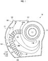
- An air conditioning unit 10 and a heat exchanger 20 configuring the air conditioning unit 10 will be described with reference to Figs. 1 to 6 .
- the air conditioning unit 10 and the heat exchanger 20 can be used, for example, in air conditioning of the interior of a vehicle as will be described below.
- An air conditioner 1 ( Fig. 4 ) including the air conditioning unit 10 is mounted on, for example, the vehicle.
- the air conditioning unit 10 is provided in a vehicle interior In ( Fig. 4 ).
- the air conditioning unit 10 shown in Fig. 1 can configure the air conditioner 1 shown in Fig. 4 .
- the air conditioner 1 will be described.
- the air conditioning unit 10 ( Fig. 1 ) includes the heat exchanger 20 (first heat exchanger) that causes air and a coolant to exchange heat with each other, a blower 11 that supplies air to the heat exchanger 20, an air outflow portion 12 (121 to 123) through which air, which has passed through the heat exchanger 20, flows out from the air conditioning unit 10, and a duct 13 in which the heat exchanger 20 is disposed.
- the duct 13 also serves as a casing of the air conditioning unit 10.
- One heat exchanger 20 included in the air conditioning unit 10 is sufficient. Unlike an HVAC unit in an example of the related art shown in Fig. 9 including two heat exchangers (91 and 92), the air conditioning unit 10 includes only one heat exchanger 20. The air conditioning unit 10 does not include elements corresponding to an air mix damper 93 and a mixing region 94 included in the HVAC unit shown in Fig. 9 .
- the air conditioning unit 10 is a so-called heating, ventilation, and air conditioning (HVAC), and has functions of cooling, heating, dehumidifying, and ventilating of the vehicle interior.
- HVAC heating, ventilation, and air conditioning
- the air conditioning unit 10 can be provided inside an interior panel such as a vehicle instrument panel.
- an upper side and a lower side of Fig. 1 correspond to an upper side and a lower side of the air conditioning unit 10 in a vertical direction
- a left side of Fig. 1 corresponds to a front side in a vehicle traveling direction
- a right side of Fig. 1 corresponds to a rear side in the vehicle traveling direction.
- the air conditioning unit 10 can be provided in an appropriate posture.
- the air conditioning unit 10 supplies air sucked by the blower 11 to the heat exchanger 20, and causes the air, of which a temperature is regulated by passing through the heat exchanger 20, to flow out from the air outflow portion 12.
- Fig. 1 the flow of air from the blower 11 to the air outflow portion 12 is schematically shown with solid arrows.
- the air flowed out from the air outflow portion 12 passes through a flow channel (not shown) to a plurality of blowing ports 31 to 33 ( Figs. 3A and 3B ) provided in the interior panel, and is blown out to the vehicle interior.
- the blowing ports 31 to 33 are, for example, the blowing port 31 for a face, through which air blows out toward the face of an occupant, the blowing port 32 for a window, through which air blows out toward a window of the vehicle, and the blowing port 33 for feet, through which air blows out toward the feet of the occupant. It is preferable that positions where the blowing ports 31 to 33 are provided in the panel of the vehicle interior are determined such that temperature-controlled air is efficiently supplied toward a supply destination such as the face, the window, and the feet.
- air having an appropriate temperature can be supplied to each supply destination through each of the blowing ports 31 to 33.
- T1 ⁇ T2 ⁇ T3 an appropriate temperature of air blown out from the blowing port 31 for a face
- T3 an appropriate temperature of air blown out from the blowing port 32 for a window
- T3 an appropriate temperature of air blown out from the blowing port 33 for feet
- the blower 11 By being rotationally driven by a drive force of a motor (not shown), the blower 11 sucks air outside the vehicle (outside air) or air in the vehicle (inside air) from a suction portion 11A ( Fig. 4 ) according to the selection of an outside air/inside air mode of the air conditioning unit 10.
- the air sucked by the blower 11 is discharged from a discharge portion 11B ( Fig. 1 ) into the duct 13, and is supplied to the heat exchanger 20.
- the heat exchanger 20 By causing air supplied from the blower 11 and a coolant supplied from a coolant circuit CL shown in Fig. 4 to exchange heat with each other, the heat exchanger 20 ( Figs. 1 to 3B ) obtains temperature-controlled air.
- a high-temperature-side coolant and a low-temperature-side coolant are obtained through heat exchange with a refrigerant circulating in a refrigerant circuit 40 ( Fig. 4 ) that is a heat pump cycle, which compresses the refrigerant and transports the refrigerant to a heat load with outside air as a heat source, and the refrigerant is supplied to the heat exchanger 20.
- a refrigerant circuit 40 Fig. 4
- the coolant is, for example, a liquid for a heat medium such as pure water and brine, and water that cools an engine mounted on the vehicle can be used as the coolant.
- the heat exchanger 20 includes a plurality of stacked flat tubes 21, a plurality of fins 22, an inlet header 23, and an outlet header 24.
- each of the tubes 21 extends parallel to each other from an upstream end portion 21A on an upstream side, in which the coolant flows, to a downstream end portion 21B on a downstream side.
- Each of the tubes 21 extends in a direction orthogonal to the page of Fig. 1 .
- the tubes 21 can be formed by extrusion molding and roll molding using, for example, metallic materials excellent in thermal conductivity, such as copper, a copper alloy, aluminum, and an aluminum alloy.
- metallic materials excellent in thermal conductivity such as copper, a copper alloy, aluminum, and an aluminum alloy.
- the fins 22 and the headers 23 and 24 can also be molded through an appropriate method using the same metallic materials as the tubes 21.
- the fins 22 are thermally coupled to the tubes 21, are formed in a shape appropriate for increasing a heat transfer area between air and a coolant, and are assembled with the tubes 21.
- the fins 22 may be, for example, a corrugated type which is formed in a wavy shape and in which the fins are stacked alternately with the tubes 21, or may be a plate type in which the fins are disposed orthogonally to each of the stacked tubes 21.
- a heat exchange core 20C having first to nth stages is configured by n tubes 21 and the plurality of fins 22 assembled with the tubes 21. Air is supplied in a direction D1 intersecting a direction D3 ( Fig. 2 ), in which a coolant flows in the tubes 21, to an air supply surface 20A of the heat exchange core 20C by the blower 11. The air supplied to the air supply surface 20A exchanges heat with the coolant flowing in the tubes 21 while passing through a gap between the fins 22.
- the direction D1 in which the air supplied to the heat exchanger 20 passes through the heat exchanger 20 will be called the air flow direction D1
- the direction D3 in which the coolant flows in the tubes 21 will be called the coolant flow direction D3.
- the inlet header 23 and the outlet header 24 extend in a direction (D2) in which the tubes 21 are stacked.
- a coolant flows into each of the stacked tubes 21 through the inlet header 23, and the coolant flowing in each of the tubes 21 flows out to the coolant circuit CL ( Fig. 4 ) through the outlet header 24.
- the inlet header 23 includes a space communicating with the upstream end portion 21A of each of the first stage tube 21 to the nth stage tube 21. An opening into which the upstream end portion 21A of each of the tubes 21 is inserted is formed in the inlet header 23.
- the outlet header 24 includes a space communicating with the downstream end portion 21B of each of the first stage tube 21 to the nth stage tube 21. An opening into which the downstream end portion 21B of each of the tubes 21 is inserted is formed in the outlet header 24.
- the tubes 21, the fins 22, the inlet header 23, and the outlet header 24 are bonded to each other, for example, through brazing.
- the heat exchanger 20 of the present embodiment has a shape curved with respect to the air flow direction D1, in which air passes through the heat exchanger 20, as a whole.
- the heat exchange core 20C has a shape of which a central portion in a direction of each of the first to nth stages (stacking direction) is curved in a direction of being convex downstream in the direction of flow of air with respect to both end portions.
- the inlet header 23 and the outlet header 24 also have a shape curved in the same direction.
- the heat exchanger 20 can be comfortably disposed inside the duct 13 under the restriction of a space allowed in the vehicle for providing the air conditioning unit 10.
- the heat exchanger 20 may be curved in an opposite direction to the direction shown in Fig. 1 in order to avoid other in-vehicle devices.
- the heat exchanger 20 is not necessarily curved.
- the heat exchanger 20 has a main feature in coolant inflow portions 231 and 232 ( Figs. 1 to 3B ) through which a coolant can flow into the inlet header 23.
- the inlet header 23 includes the low-temperature-side coolant inflow portion 231 and the high-temperature-side coolant inflow portion 232, which correspond to coolants having temperatures different from each other, respectively.
- a coolant flows into the inlet header 23 through at least one of the coolant inflow portions 231 and 232.
- a coolant LC low-temperature-side coolant that has a relatively low temperature can flow into the low-temperature-side coolant inflow portion 231 from a low-temperature-side coolant circuit 60 to be described later.
- a coolant HC high-temperature-side coolant that has a relatively high temperature can flow into the high-temperature-side coolant inflow portion 232 from a high-temperature-side coolant circuit 50 to be described later, independently of the low-temperature-side coolant inflow portion 231.
- the low-temperature-side coolant inflow portion 231 and the high-temperature-side coolant inflow portion 232 are shifted from each other in the air flow direction D1 and are shifted from each other in the intersecting direction D2 intersecting the air flow direction D1.
- a temperature gradient in the intersecting direction D2 is given to air that is supplied to the heat exchanger 20 by the blower 11 and has exchanged heat with a coolant flowing in the tubes 21. This will be described later.
- the intersecting direction D2 intersects both of the air flow direction D1 and the coolant flow direction D3.
- the low-temperature-side coolant inflow portion 231 is shifted on to upstream side in the air flow direction D1 from the high-temperature-side coolant inflow portion 232 in order to dehumidify air.
- the air outflow portion 12 ( Fig. 1 ) corresponds to an opening provided in a wall of the duct 13 in which air flows.
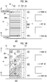
- a temperature gradient in the intersecting direction D2 intersecting the air flow direction D1 is given to air supplied to the heat exchanger 20 as passing through the heat exchanger 20. For this reason, it is possible to cause air having a temperature suitable for each of the blowing ports 31 to 33 to flow out from a position of a temperature range suitable for each of the blowing ports 31 to 33 in a region 131 ( Figs. 3A and 3B ), which is adjacent to a downstream side of the heat exchanger 20 and extends in the intersecting direction D2, toward each of the blowing ports 31 to 33.
- Air which has passed through the heat exchanger 20 and is in a relatively different temperature range, flows out through the air outflow portion 12 toward each of the blowing port 31 for a face, the blowing port 32 for a window, and the blowing port 33 for feet.
- the air outflow portion 12 is formed by the plurality of air outflow portions 121 to 123 individually corresponding to the plurality of blowing ports 31 to 33. Specifically, the air outflow portion 12 is formed by the low-temperature-side air outflow portion 121 through which air having a relatively low temperature flows out, the medium temperature air outflow portion 122 through which air having a relatively medium temperature flows out, and the high-temperature-side air outflow portion 123 through which air having a relatively high temperature flows out.
- the air outflow portions 121 to 123 are openings independent of each other, and are provided in the duct 13 by selecting a position where air having a temperature suitable for a corresponding blowing port is to be taken out from the region 131.
- the air outflow portions 121 to 123 may not necessarily be independent of each other, or the air outflow portions at positions close to each other are allowed to be integrated as one opening.
- a blowing port corresponding to each of the air outflow portions 121 to 123 can be determined as appropriate in consideration of keeping the head cool and the feet warm.
- the low-temperature-side air outflow portion 121 corresponds to the blowing port 31 for a face
- the medium temperature air outflow portion 122 corresponds to the blowing port 32 for a window
- the high-temperature-side air outflow portion 123 corresponds to the blowing port 33 for feet.
- the temperature of a side of the heat exchanger 20, which is close to the blowing port 31 for a face can be made relatively low and the temperature of a side of the heat exchanger 20, which is close to the blowing port 33 for feet, can be made relatively high according to a posture in which the heat exchanger 20 is provided and the positions of the air outflow portions 121 to 123 in the present embodiment, the occupant's comfort can be improved by keeping the head cool and the feet warm.
- the blowing port corresponding to each of the air outflow portions 121 to 123 is not limited to the present embodiment.
- the high-temperature-side air outflow portion 123 is positioned on a most upstream side of flow of air toward a trailing end 13A of the duct 13 from the heat exchanger 20, and the low-temperature-side air outflow portion 121 is positioned on a most downstream side.
- the medium temperature air outflow portion 122 through which air in a medium temperature range, which is between temperature ranges of air flowed out through the low-temperature-side air outflow portion 121 and the high-temperature-side air outflow portion 123 respectively, flows out is positioned between the high-temperature-side air outflow portion 123 and the low-temperature-side air outflow portion 121.
- each of the air outflow portions 121 to 123 it is preferable to appropriately determine the position of each of the air outflow portions 121 to 123 according to the shape of the duct 13 or the heat exchanger 20 and the position of the heat exchanger 20 in the duct 13.
- each of the air outflow portions 121 to 123 can be appropriately determined such that air flows smoothly to a corresponding blowing port while preventing a pressure loss.
- the workings of the air conditioning unit 10 will be described based on the configuration of the heat exchanger 20 ( Figs. 1 to 3B ).
- the coolant LC having a relatively low temperature flows into the inlet header 23 of the heat exchanger 20 from the low-temperature-side coolant inflow portion 231, and the coolant HC having a relatively high temperature flows into the inlet header from the high-temperature-side coolant inflow portion 232.
- the coolant LC which has flowed in from the low-temperature-side coolant inflow portion 231 mainly flows into the tube 21 disposed on a first stage side among the stacked tubes 21.
- the coolant HC which has flowed in from the high-temperature-side coolant inflow portion 232 mainly flows into the tube 21 disposed on an nth stage side among the stacked tubes 21.
- a temperature gradient in a stage direction is given to a coolant flowing in each of the tubes 21 in the coolant flow direction D3. For this reason, the same temperature gradient is given also to air that is supplied to the heat exchanger 20 by the blower 11 and gives and receives heat to and from the coolant flowing in each of the tubes 21.
- Fig. 3B shows that a temperature gradient existing in a coolant flowing in the tube 21 of each stage in the heat exchanger 20 is in a pattern different for each temperature range.
- a relationship as to which temperature ranges B1, B2, B3, B4, and B5 are higher or lower is B1 ⁇ B2 ⁇ B3 ⁇ B4 ⁇ B5. Since such a temperature gradient is given to air that gives and receives heat to and from the coolant while passing through the heat exchanger 20, flow F of air that has immediately passed through the heat exchanger 20 from the first to nth stages also has the same temperature gradient as the temperature gradient shown in Fig. 3B .
- a direction in which the coolant inflow portions 231 and 232 are shifted from each other is set such that the low-temperature-side coolant inflow portion 231 is positioned on the upstream side in the air flow direction D1 with respect to the high-temperature-side coolant inflow portion 232.
- a large amount of air supplied to the heat exchanger 20 passes through the temperature ranges B1 and B2 in which the temperature of a coolant is relatively low.
- the heat exchanger 20 is shown in a shape simplified into a rectangular shape in Figs. 3A and 3B , the same temperature gradient as shown in Fig. 3B is given to air, which has passed through the heat exchanger 20, even when the heat exchanger 20 is curved as shown in Figs. 1 and 2 , based on the fact that the positions of the low-temperature-side coolant inflow portion 231 and the high-temperature-side coolant inflow portion 232 are shifted from each other.
- the heat exchanger 20 may actually be formed in a rectangular shape.
- the low-temperature-side coolant inflow portion 231 and the high-temperature-side coolant inflow portion 232 are shifted from each other in the air flow direction D1 and the intersecting direction D2, a temperature gradient is given to the region 131 adjacent to the downstream side of the heat exchanger 20.
- the air temperature is distributed in the stage direction from the first to nth stages, that is, in the region 131 over a wide range in the intersecting direction D2.
- air in a temperature range suitable for each supply destination can be easily and reliably distributed to a plurality of supply destinations, to which temperature-controlled air is to be supplied, from the region 131 of the present embodiment by selecting an appropriate position and causing air in an appropriate temperature to flow out through the air outflow portion 12 (121 to 123) provided in the duct 13.
- the heat exchanger 20 is disposed to extend in the up-and-down direction in general as in the present embodiment
- the high-temperature-side air outflow portion 123 is positioned at a lowermost position among the air outflow portions 121 to 123, and is close to the position of the blowing port 33 for feet, which is usually positioned in the lower part of the vehicle interior. For this reason, a sufficient amount of air can be supplied from the high-temperature-side air outflow portion 123 to the blowing port 33 for feet while preventing a pressure loss.
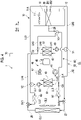
- the air conditioner 1 including the air conditioning unit 10 will be described with reference to Fig. 4 .
- functions of cooling and heating can be performed with only one heat exchanger 20 given to the air conditioning unit 10 as a low-temperature-side coolant (for example, chilled water) and a high-temperature-side coolant (for example, warm water) are suppliable to the heat exchanger 20 of the air conditioning unit 10.
- a low-temperature-side coolant for example, chilled water
- a high-temperature-side coolant for example, warm water
- each of a condenser 43 and an evaporator 49 of a steam compression refrigerating cycle exchanges heat with a coolant.
- the air conditioner 1 includes the refrigerant circuit 40, the coolant circuit CL that includes the high-temperature-side coolant circuit 50 and the low-temperature-side coolant circuit 60, the air conditioning unit 10 described above, a vehicle exterior heat exchanger CL1 (second heat exchanger), a fan CL2, and a controller 70 that controls an operation of the air conditioner 1.
- the air conditioner 1 is provided with a first regulating valve V1, a second regulating valve V2, a third regulating valve V3, a first electromagnetic valve SV1, and a second electromagnetic valve SV2. The valves are controlled by the controller 70.
- the high-temperature-side coolant circuit 50 sends a coolant having a high temperature, which has exchanged heat with a high temperature refrigerant through the condenser 43, and regulates the distribution of the flow rate of a coolant to be sent to each of the vehicle exterior heat exchanger CL1 and the heat exchanger 20 (vehicle interior heat exchanger) of the air conditioning unit 10 through the first regulating valve V1 according to an air conditioning load.
- the low-temperature-side coolant circuit 60 sends a coolant having a low temperature, which has exchanged heat with a low temperature refrigerant through the evaporator 49, and regulates the distribution of the flow rate of a coolant to be sent to each of the vehicle exterior heat exchanger CL1 and the heat exchanger 20 through the second regulating valve V2 according to an air conditioning load.
- the air conditioner 1 has a configuration described below in order to realize the functions described above.
- the refrigerant circuit 40 is provided in a vehicle exterior Out.
- the refrigerant circuit 40 includes a compressor 41 that compresses a refrigerant, the condenser 43 that is a heat exchanger which performs heat exchange between a high temperature and high pressure gas refrigerant compressed by the compressor 41 and a high-temperature-side coolant flowing in the high-temperature-side coolant circuit 50, a liquid receiver 45, an expansion valve 47 that is a decompression unit which decompresses a refrigerant flowing out from the liquid receiver 45, and the evaporator 49 that is a heat exchanger which performs heat exchange between the refrigerant decompressed by the expansion valve 47 and a low-temperature-side coolant flowing in the low-temperature-side coolant circuit 60.
- the high temperature and high pressure gas refrigerant exchanges heat with the high-temperature-side coolant and is condensed by the condenser 43. At this time, since the gas refrigerant releases condensation heat, the temperature of the high-temperature-side coolant used in cooling rises. The state of the refrigerant changes from a gas to a liquid due to condensation, and becomes a high temperature and high pressure liquid. The liquid refrigerant flows into the liquid receiver 45.
- the expansion valve 47 releases a refrigerant after restricting the flow of a high temperature and high pressure liquid refrigerant, the pressure of the refrigerant drops sharply. For this reason, a refrigerant in the evaporator 49 easily evaporates. In the evaporator 49, the refrigerant evaporates by taking away evaporation heat from a low-temperature-side coolant. For this reason, the temperature of the low-temperature-side coolant decreases. The low temperature and low pressure gas refrigerant which has passed through the evaporator 49 flows into the compressor 41, and is compressed into a high temperature and high pressure gas refrigerant. A refrigerating cycle is repeated from each of processes including condensation by the condenser 43, decompression by the expansion valve 47, and evaporation by the evaporator 49, in addition to the compression of the gas refrigerant.
- the high-temperature-side coolant circuit 50 includes a high-temperature-side heat exchanger 51 that is provided side by side with the condenser 43 of the refrigerant circuit 40 and performs heat exchange between a refrigerant flowing in the condenser 43 and a high-temperature-side coolant and a high-temperature-side circulation pump 53 that circulates the high-temperature-side coolant.
- the first regulating valve V1 regulates the flow of a high-temperature-side coolant to any one or both of the heat exchanger 20 and the vehicle exterior heat exchanger CL1.
- the first regulating valve V1 can be configured by a so-called three-way valve, and can regulate the distribution of the high-temperature-side coolant flowing in the heat exchanger 20 and the vehicle exterior heat exchanger CL1.
- the regulating valve can regulate the flow rate.
- the third regulating valve V3 regulates the flow of a coolant flowed out from the heat exchanger 20 to any one or both of the high-temperature-side coolant circuit 50 and the low-temperature-side coolant circuit 60.
- the first electromagnetic valve SV1 and the second electromagnetic valve SV2 selectively cause any one of a high-temperature-side coolant and a low-temperature-side coolant to flow into the vehicle exterior heat exchanger CL1.
- the first electromagnetic valve SV1 allows or prevents the coolant from the vehicle exterior heat exchanger CL1 from flowing into the high-temperature-side heat exchanger 51 via an exhaust heat collector 68.
- the second electromagnetic valve SV2 allows or prevents the coolant from the vehicle exterior heat exchanger CL1 from flowing into an exhaust heat collector 67.
- the high-temperature-side circulation pump 53 has one end connected to a downstream side of the high-temperature-side heat exchanger 51 and the other end provided on a flow channel of a pipe LH1 connected to the first regulating valve V1.
- the downstream side is based on a direction in which a high-temperature-side coolant flows in the high-temperature-side heat exchanger 51.
- One end of a pipe LH2 and one end of a pipe LH3 are connected to the first regulating valve V1.
- the other end of the pipe LH2 is connected to the vehicle exterior heat exchanger CL1 via a connection pipe 27.
- the other end of the pipe LH3 is connected to the inlet header 23 ( Fig. 2 ) of the heat exchanger 20 via a connection pipe 252.
- One end of a pipe LH6 is connected to an upstream side of the high-temperature-side heat exchanger 51, and a confluence point C3 is provided at the other end of the pipe LH6.
- One end of a pipe LH4 and one end of a pipe LH5 are connected to the confluence point C3.
- the other end of the pipe LH4 is connected to the vehicle exterior heat exchanger CL1 via a connection pipe 28, and is also connected to a pipe LL2 of the low-temperature-side coolant circuit 60.
- the first electromagnetic valve SV1 described above is provided on a flow channel of the pipe LH4.
- the other end of the pipe LH5 is connected to the third regulating valve V3.
- the third regulating valve V3 is connected to the outlet header 24 ( Fig. 2 ) of the heat exchanger 20 via a connection pipe 26.
- arrows shown in the pipes LH1 to LH6 indicate a direction in which a high-temperature-side coolant flows. Although the direction in which the high-temperature-side coolant flows is shown for all of the pipes LH1 to LH6 in Fig. 4 , there also is a pipe in which the high-temperature-side coolant does not flow, among the pipes LH1 to LH6, depending on an operation mode of the air conditioner 1. The same applies to pipes LL1 to LL6 to be described later.
- the low-temperature-side coolant circuit 60 includes a low-temperature-side heat exchanger 61 that is provided side by side with the evaporator 49 of the refrigerant circuit 40 and performs heat exchange between a refrigerant flowing in the evaporator 49 and a low-temperature-side coolant, a low-temperature-side circulation pump 63 that circulates the low-temperature-side coolant, and the exhaust heat collectors 67 and 68 that collect heat from air discharged from the vehicle interior In to the outside.
- a low-temperature-side heat exchanger 61 that is provided side by side with the evaporator 49 of the refrigerant circuit 40 and performs heat exchange between a refrigerant flowing in the evaporator 49 and a low-temperature-side coolant
- a low-temperature-side circulation pump 63 that circulates the low-temperature-side coolant
- the exhaust heat collectors 67 and 68 that collect heat from air discharged from the vehicle interior In to the outside.
- a heat exchanger or an electric heater that collects vehicle device exhaust heat or ventilation exhaust heat can also be provided.
- the second regulating valve V2 regulates the flow of a low-temperature-side coolant to any one or both of the heat exchanger 20 and the vehicle exterior heat exchanger CL1.
- the second regulating valve V2 can be configured by a so-called three-way valve, and can regulate the distribution of the low-temperature-side coolant flowing in the heat exchanger 20 and the vehicle exterior heat exchanger CL1.
- the low-temperature-side circulation pump 63 has one end connected to a downstream side of the low-temperature-side heat exchanger 61 and the other end provided on a flow channel of the pipe LL1 connected to the second regulating valve V2.
- One end of the pipe LL2 and one end of the pipe LL3 are connected to the second regulating valve V2.
- the exhaust heat collector 68 and the first electromagnetic valve SV1 are provided on a flow channel of the pipe LL2.
- the other end of the pipe LL2 is connected to the vehicle exterior heat exchanger CL1 via the connection pipe 28.
- the other end of the pipe LL3 is connected to the heat exchanger 20 via a connection pipe 251.
- One end of the pipe LL6 is connected to an upstream side of the low-temperature-side heat exchanger 61, and a confluence point C5 is provided at the other end of the pipe LL6.
- One end of the pipe LL4 and one end of the pipe LL5 are connected to the confluence point C5.
- the other end of the pipe LL4 is connected to the third regulating valve V3.
- the other end of the pipe LL5 is connected to the vehicle exterior heat exchanger CL1 via the connection pipe 27, and is also connected to the pipe LH2 of the high-temperature-side coolant circuit 50.
- the exhaust heat collector 67 and the second electromagnetic valve SV2 are provided on a flow channel of the pipe LL5.
- the high-temperature-side heat exchanger 51 continuously performs heat exchange between a high temperature and high pressure gas refrigerant and a high-temperature-side coolant
- the low-temperature-side heat exchanger 61 continuously performs heat exchange between a refrigerant decompressed by the expansion valve 47 and a low-temperature-side coolant.
- the air conditioner 1 realizes a plurality of operation modes by distributing the high-temperature-side coolant and the low-temperature-side coolant to the heat exchanger 20 and the vehicle exterior heat exchanger CL1.
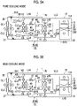
- the air conditioner 1 of the present embodiment operates in any one of four modes including the pure cooling mode shown in Fig. 5A , the mild cooling mode shown in Fig. 5B , a mild heating and dehumidified heating mode shown in Fig. 6A , and a pure heating mode shown in Fig. 6B .
- a low-temperature-side coolant is sent to the heat exchanger 20 by the low-temperature-side coolant circuit 60, and a high-temperature-side coolant flowing in the high-temperature-side coolant circuit 50 circulates between the high-temperature-side heat exchanger 51 and the vehicle exterior heat exchanger CL1.
- the first regulating valve V1, the third regulating valve V3, the second regulating valve V2, the first electromagnetic valve SV1, and the second electromagnetic valve SV2 are controlled as follows.
- ON means that a flow channel is open, and OFF means that the flow channel is closed.
- a flow channel section where a coolant does not flow as the valve is turned off is shown by a broken line.
- a high-temperature-side coolant circulates in the high-temperature-side heat exchanger 51, the high-temperature-side circulation pump 53, the first regulating valve V1, and the vehicle exterior heat exchanger CL1 in this order. That is, the high-temperature-side coolant is not sent to the heat exchanger 20, and circulates in the closed high-temperature-side coolant circuit 50.
- a low-temperature-side coolant circulates in the low-temperature-side heat exchanger 61, the low-temperature-side circulation pump 63, the second regulating valve V2, the heat exchanger 20, and the third regulating valve V3 in this order.
- the low-temperature-side coolant is not sent to the vehicle exterior heat exchanger CL1.
- the low-temperature-side coolant circuit 60 sends a low-temperature-side coolant to the heat exchanger 20
- the high-temperature-side coolant circuit 50 sends some of a high-temperature-side coolant to the heat exchanger 20 and sends the remaining high-temperature-side coolant to the vehicle exterior heat exchanger CL1.
- the first regulating valve V1, the third regulating valve V3, the second regulating valve V2, the first electromagnetic valve SV1, and the second electromagnetic valve SV2 are controlled as follows.
- a high-temperature-side coolant circulates in the high-temperature-side heat exchanger 51, the high-temperature-side circulation pump 53, the first regulating valve V1, the heat exchanger 20, and the third regulating valve V3 in this order, and circulates in the high-temperature-side heat exchanger 51, the high-temperature-side circulation pump 53, the first regulating valve V1, and the vehicle exterior heat exchanger CL1 in this order.
- a low-temperature-side coolant circulates in the same manner as in the pure cooling mode.
- the high-temperature-side coolant circuit 50 sends a high-temperature-side coolant to the heat exchanger 20, sends some of a low-temperature-side coolant flowing in the low-temperature-side coolant circuit 60 to the heat exchanger 20, and sends the remaining low-temperature-side coolant to the vehicle exterior heat exchanger CL1.
- both of a low-temperature-side coolant and a high-temperature-side coolant are supplied to the heat exchanger 20 as in the mild cooling mode.
- the flow rate of the low-temperature-side coolant supplied to the heat exchanger 20 is low compared to the mild cooling mode, and conversely, the flow rate of the high-temperature-side coolant is high.
- the degree of heating is lower than in the pure heating mode ( Fig. 6B ) in which the low-temperature-side coolant is not supplied to the heat exchanger 20.
- the first regulating valve V1, the third regulating valve V3, the second regulating valve V2, the first electromagnetic valve SV1, and the second electromagnetic valve SV2 are controlled as follows.
- a high-temperature-side coolant circulates in the high-temperature-side heat exchanger 51, the high-temperature-side circulation pump 53, the first regulating valve V1, the heat exchanger 20, and the third regulating valve V3 in this order.
- a low-temperature-side coolant circulates in the low-temperature-side heat exchanger 61, the low-temperature-side circulation pump 63, the second regulating valve V2, the heat exchanger 20, and the third regulating valve V3 in this order, and circulates in the low-temperature-side heat exchanger 61, the low-temperature-side circulation pump 63, the second regulating valve V2, the exhaust heat collector 68, the vehicle exterior heat exchanger CL1, and the exhaust heat collector 67 in this order.
- a high-temperature-side coolant is sent to the heat exchanger 20 by the high-temperature-side coolant circuit 50, and a low-temperature-side coolant flowing in the low-temperature-side coolant circuit 60 circulates between the low-temperature-side heat exchanger 61 and the vehicle exterior heat exchanger CL1.
- the first regulating valve V1, the third regulating valve V3, the second regulating valve V2, the first electromagnetic valve SV1, and the second electromagnetic valve SV2 are controlled as follows.
- a high-temperature-side coolant circulates in the high-temperature-side heat exchanger 51, the high-temperature-side circulation pump 53, the first regulating valve V1, the heat exchanger 20, and the third regulating valve V3 in this order.
- a low-temperature-side coolant circulates in the low-temperature-side heat exchanger 61, the low-temperature-side circulation pump 63, the second regulating valve V2, the exhaust heat collector 68, the vehicle exterior heat exchanger CL1, and the exhaust heat collector 67 in this order.
- the air conditioner 1 of the present embodiment one or both of a high-temperature-side coolant heated as exchanging heat with a refrigerant in the refrigerant circuit 40 by means of the high-temperature-side coolant circuit 50 and a low-temperature-side coolant cooled as exchanging heat with the refrigerant in the refrigerant circuit 40 by means of the low-temperature-side coolant circuit 60 are supplied to the heat exchanger 20.
- the air conditioner 1 can perform cooling and heating as described above even when only one heat exchanger 20 is provided in the air conditioning unit 10.
- the air conditioning unit 10 can be miniaturized. As is clear from comparing the air conditioning unit 10 shown in Fig. 1 to the HVAC unit shown in Fig. 9 , the volume of the air conditioning unit 10 is smaller than the volume of the HVAC unit including the two heat exchangers (91 and 92) by a region indicated with a shaded pattern in Fig. 9 .
- the air conditioner 1 since the air conditioner 1 has only one heat exchanger 20, it is not necessary to include the air mix damper (93 of Fig. 9 ). Accordingly, the following effects are obtained.
- Wind noise generated when the opening degree of the air mix damper is particularly small can be eliminated.
- a driving source such as a motor that drives the air mix damper is not necessary, and a moving portion in the air conditioning unit 10 can be eliminated by eliminating the air mix damper. For this reason, the weight and cost of the air conditioning unit 10 can be reduced, and reliability can be improved.
- the air conditioner 1 since the refrigerant circuit 40 is provided in the vehicle exterior Out, the air conditioner 1 has a low risk of a refrigerant leaking to the vehicle interior In. Therefore, a heating capacity can be increased by using a refrigerant (R454C) having considerable combustibility and a high pressure refrigerant such as CO 2 without necessarily preventing a refrigerant leak by increasing the size of a device configuring the refrigerant circuit 40.
- a refrigerant R454C
- a high pressure refrigerant such as CO 2
- an evaporation temperature (low pressure) of the evaporator 49 depends on the outside air temperature.
- the temperature of a low-temperature-side coolant that exchanges heat with a refrigerant by means of the low-temperature-side heat exchanger 61 and is supplied to the heat exchanger 20 used in dehumidifying also corresponds to the evaporation temperature.
- the temperature of the low-temperature-side coolant flowing in the heat exchanger 20 can be maintained at 0°C or higher through mixing between the low-temperature-side coolant and a high-temperature-side coolant in the coolant circuit CL. For this reason, heating performance can be maintained by preventing frost on the heat exchanger 20.
- Each operation mode of the air conditioner 1, which is described above, is merely an example, and is not limited to the description above.
- a small amount of high-temperature-side coolant is also supplied to the inlet header 23 of the heat exchanger 20 while a low-temperature-side coolant is supplied in the pure cooling mode
- a small amount of low-temperature-side coolant is also supplied to the inlet header 23 of the heat exchanger 20 while the high-temperature-side coolant is supplied in the pure heating mode.
- a temperature gradient can be given to air which has passed through the heat exchanger 20, and keeping the head cool and the feet warm can be achieved.
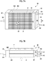
- a heat exchanger 80 according to a second embodiment of the present invention will be described with reference to Figs. 7A to 8 .
- points different from the first embodiment will be mainly described.
- the heat exchanger 80 includes a plurality of rows (801 and 802) of the tubes 21 arranged in the air flow direction D1, the fins 22 appropriately provided on the tubes 21, an inlet header 23, and the outlet header 24.
- the heat exchanger 80 can configure, for example, the air conditioner 1 shown in Fig. 4 .
- a heat exchange core disposed on the upstream side in the air flow direction D1 will be called an upwind row 801, and a heat exchange core disposed on the downstream side in the air flow direction D1 will be called a downwind row 802.
- the upwind row 801 is formed by the plurality of tubes 21 stacked in the intersecting direction D2 intersecting the air flow direction D1 and the plurality of fins 22. The same applies to the downwind row 802.
- the heat exchanger 20 of the first embodiment described above may be configured to include the upwind row 801 and the downwind row 802.
- the number of the tubes 21 in the upwind row 801 and the number of the tubes 21 in the downwind row 802 are the same n, the tubes 21 in the upwind row 801 and the tubes 21 in the downwind row 802 which are at the same stage of the first to nth stages are disposed at the same position in the intersecting direction D2.
- the number of the tubes 21 may be different between the upwind row 801 and the downwind row 802, and the positions of the tubes 21 in the upwind row 801 and the downwind row 802 which are at the same stage may be shifted from each other in the intersecting direction D2.
- the inside of the inlet header 23 communicates with all of the tubes 21 in the upwind row 801 and all of the tubes 21 in the downwind row 802. The same applies also to the inside of the outlet header 24.
- the second embodiment has a main feature that the inside of the inlet header 23 is divided into a low-temperature-side section A1 into which a low-temperature-side coolant can flow from the low-temperature-side coolant inflow portion 231 and a high-temperature-side section A2 into which a high-temperature-side coolant can flow from the high-temperature-side coolant inflow portion 232.
- the inside of the inlet header 23 is divided into the low-temperature-side section A1 and the high-temperature-side section A2 by a panel-shaped partition member 85 disposed along the stage direction.
- the low-temperature-side coolant inflow portion 231 is shifted to the upstream side (upwind side) in the air flow direction D1 with respect to the high-temperature-side coolant inflow portion 232 as in the first embodiment.
- the low-temperature-side section A1 into which a low-temperature-side coolant can flow is positioned on the upstream side (upwind side) in the air flow direction D1 inside the inlet header 23
- the high-temperature-side section A2 into which a high-temperature-side coolant can flow is positioned on the downstream side (downwind side) in the air flow direction D1 inside the inlet header 23.
- the low-temperature-side section A1 communicates with the tubes 21 in the upwind row 801
- the high-temperature-side section A2 communicates with the tubes 21 in the downwind row 802.
- the inside of the inlet header 23 is divided into the low-temperature-side section A1 and the high-temperature-side section A2. That is, the inside of the inlet header 23 is not completely partitioned.
- the partition member 85 is disposed inside the inlet header 23 with the gap 851 between an end edge thereof and an inner wall of the inlet header 23.
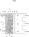
- Fig. 8 schematically shows a temperature gradient of a coolant flowing in each of the tubes 21 of the heat exchanger 80 of the second embodiment.
- the coolant HC which has flowed from the high-temperature-side coolant inflow portion 232 into the high-temperature-side section A2 mainly flows into the tubes 21 disposed particularly on the nth stage side of the downwind row 802.
- a temperature difference between the upwind side and the downwind side is emphasized in a temperature gradient given to the coolant flowing in each of the tubes 21.
- a capacity of dehumidifying air in the vehicle interior can be improved and fogging of a window can be sufficiently prevented since a low-temperature-side coolant is easily distributed to the tubes 21 on the upwind side.
- the configuration for dividing into the low-temperature-side section A1 and the high-temperature-side section A2 while allowing the movement of a coolant is not limited to the present embodiment.
- the partition member instead of providing the gap 851 between the end edge of the partition member 85 and an inner wall of the inlet header 23, the partition member may have a hole through which the coolant can enter and exit.
- the inlet header 23 is formed by two separate tubular bodies, and the tubular bodies may be configured to communicate with each other via a passage through which the coolant passes.
- the heat exchanger 80 may include the tubes 21 arranged in three or more rows.
- the tubes 21 in a first row positioned on the upwind side communicate with the low-temperature-side section A1
- the remaining tubes 21 in a second row and a third row communicate with the high-temperature-side section A2.
- the heat exchanger, the air conditioning unit, and the air conditioner of the present invention are not limited for use in vehicles, and can also be applied to air conditioning of buildings.
- the air conditioning unit 10 includes the three air outflow portions 121 to 123 in the embodiments, the air conditioning unit of the present invention may include only two air outflow portions.
- the two air outflow portions may correspond to the blowing port for a face and the blowing port for a window, may correspond to the blowing port for a window and the blowing port for feet, or may correspond to the blowing port for a face and the blowing port for feet.
- the air conditioning unit of the present invention may include four or more air outflow portions.
Landscapes
- Engineering & Computer Science (AREA)
- Mechanical Engineering (AREA)
- Physics & Mathematics (AREA)
- Thermal Sciences (AREA)
- General Engineering & Computer Science (AREA)
- Chemical & Material Sciences (AREA)
- Combustion & Propulsion (AREA)
- Geometry (AREA)
- Air-Conditioning For Vehicles (AREA)
Applications Claiming Priority (2)
| Application Number | Priority Date | Filing Date | Title |
|---|---|---|---|
| JP2019122641A JP7329373B2 (ja) | 2019-07-01 | 2019-07-01 | 空気調和ユニット、熱交換器、および空気調和機 |
| PCT/JP2020/025205 WO2021002288A1 (fr) | 2019-07-01 | 2020-06-26 | Unité de climatisation, échangeur de chaleur et climatiseur |
Publications (3)
| Publication Number | Publication Date |
|---|---|
| EP3995774A1 true EP3995774A1 (fr) | 2022-05-11 |
| EP3995774A4 EP3995774A4 (fr) | 2023-07-26 |
| EP3995774B1 EP3995774B1 (fr) | 2025-04-16 |
Family
ID=74100346
Family Applications (1)
| Application Number | Title | Priority Date | Filing Date |
|---|---|---|---|
| EP20834952.2A Active EP3995774B1 (fr) | 2019-07-01 | 2020-06-26 | Unité de climatisation, échangeur de chaleur et climatiseur |
Country Status (5)
| Country | Link |
|---|---|
| US (1) | US12104819B2 (fr) |
| EP (1) | EP3995774B1 (fr) |
| JP (1) | JP7329373B2 (fr) |
| CN (1) | CN114072297B (fr) |
| WO (1) | WO2021002288A1 (fr) |
Families Citing this family (2)
| Publication number | Priority date | Publication date | Assignee | Title |
|---|---|---|---|---|
| US20250018771A1 (en) * | 2021-11-04 | 2025-01-16 | Mitsubishi Heavy Industries Thermal Systems, Ltd. | Vehicular refrigeration cycle unit and vehicular air conditioning device |
| KR20250054323A (ko) * | 2023-10-16 | 2025-04-23 | 주식회사 에스씨에스 | 쿨링 모듈 |
Family Cites Families (56)
| Publication number | Priority date | Publication date | Assignee | Title |
|---|---|---|---|---|
| JPH0241502Y2 (fr) * | 1984-09-28 | 1990-11-05 | ||
| JPH02185821A (ja) * | 1989-01-12 | 1990-07-20 | Diesel Kiki Co Ltd | 自動車用空調装置 |
| DE4227565C1 (de) | 1992-08-20 | 1993-11-04 | Daimler Benz Ag | Waermetauscher in einem kraftfahrzeug |
| JPH06276614A (ja) * | 1993-03-17 | 1994-09-30 | Hitachi Ltd | ハイブリッド車の駆動装置 |
| JP3728855B2 (ja) * | 1997-03-21 | 2005-12-21 | トヨタ自動車株式会社 | ハイブリッド車用動力冷却装置 |
| US5896921A (en) * | 1997-05-27 | 1999-04-27 | Daewoo Electronics Co., Ltd. | Indoor unit of an air conditioner |
| WO2001015922A1 (fr) * | 1999-08-27 | 2001-03-08 | Zexel Valeo Climate Control Corporation | Climatiseur pour vehicule |
| KR100360233B1 (ko) * | 1999-09-15 | 2002-11-08 | 엘지전자 주식회사 | 선회관을 갖는 냉동사이클장치 및 공기조화기 |
| US6360817B1 (en) * | 1999-12-22 | 2002-03-26 | Visteon Global Technologies, Inc. | Single heat exchanger |
| DE10029934A1 (de) * | 2000-06-17 | 2002-01-03 | Behr Gmbh & Co | Klimaanlage mit Klimatisierungs- und Wärmepumpenmodus |
| US6880620B2 (en) * | 2002-06-25 | 2005-04-19 | Delphi Technologies, Inc. | Heating, ventilating, and air conditioning module having an improved heater core configuration |
| JP2005082079A (ja) * | 2003-09-10 | 2005-03-31 | Denso Corp | 空調装置および車両用空調装置 |
| JP2006143081A (ja) | 2004-11-22 | 2006-06-08 | Mitsubishi Heavy Ind Ltd | 空気調和ユニットおよび車両用空気調和装置 |
| JP2007155183A (ja) * | 2005-12-02 | 2007-06-21 | Showa Denko Kk | 熱交換器 |
| JP2007186066A (ja) * | 2006-01-12 | 2007-07-26 | Denso Corp | 車両用空調装置 |
| CN101915480B (zh) * | 2006-04-14 | 2014-10-29 | 三菱电机株式会社 | 热交换器及制冷空调装置 |
| JP5297154B2 (ja) | 2008-11-06 | 2013-09-25 | 三菱重工業株式会社 | 車両空調システムおよびその運転制御方法 |
| JP5413433B2 (ja) * | 2010-11-09 | 2014-02-12 | 株式会社デンソー | 熱交換器 |
| DE102010063324A1 (de) * | 2010-12-17 | 2012-06-21 | Behr Gmbh & Co. Kg | Vorrichtung zur Kühlung von Ladeluft, System zum Konditionieren von Ladeluft und Ansaugmodul für einen Verbrennungsmotor |
| JP5626194B2 (ja) * | 2010-12-21 | 2014-11-19 | 株式会社デンソー | 熱交換システム |
| JP5799792B2 (ja) * | 2011-01-07 | 2015-10-28 | 株式会社デンソー | 冷媒放熱器 |
| JP5531991B2 (ja) * | 2011-03-07 | 2014-06-25 | 株式会社デンソー | 車両用空調装置 |
| JP5659925B2 (ja) * | 2011-04-04 | 2015-01-28 | 株式会社デンソー | 車両用空調装置 |
| CN102954615B (zh) * | 2011-08-31 | 2015-12-09 | 杭州三花研究院有限公司 | 电动汽车热管理系统及电动汽车 |
| EP3222449A1 (fr) * | 2012-02-28 | 2017-09-27 | Japan Climate Systems Corporation | Climatiseur d'air pour véhicule |
| JP2013217631A (ja) * | 2012-03-14 | 2013-10-24 | Denso Corp | 冷凍サイクル装置 |
| JP6201434B2 (ja) * | 2012-07-18 | 2017-09-27 | 株式会社デンソー | 冷凍サイクル装置 |
| US10035404B2 (en) * | 2012-10-15 | 2018-07-31 | Ford Global Technologies, Llc | Thermostatically-controlled multi-mode coolant loops |
| JP6011519B2 (ja) * | 2012-12-11 | 2016-10-19 | 株式会社デンソー | 車両用熱交換装置 |
| JP5853948B2 (ja) * | 2012-12-27 | 2016-02-09 | 株式会社デンソー | 熱交換器 |
| WO2014136447A1 (fr) * | 2013-03-06 | 2014-09-12 | パナソニック株式会社 | Dispositif de climatisation de véhicule |
| JP6304578B2 (ja) * | 2013-03-06 | 2018-04-04 | パナソニックIpマネジメント株式会社 | 車両用空調装置 |
| JP6079477B2 (ja) * | 2013-06-28 | 2017-02-15 | 株式会社デンソー | 車両用空調装置 |
| JP6083339B2 (ja) * | 2013-07-09 | 2017-02-22 | 株式会社デンソー | 車両用空調装置 |
| JP6209391B2 (ja) * | 2013-08-09 | 2017-10-04 | 株式会社日本クライメイトシステムズ | 車両用空調装置 |
| JP6204110B2 (ja) * | 2013-08-09 | 2017-09-27 | 株式会社日本クライメイトシステムズ | 車両用空調装置 |
| DE102013219200A1 (de) * | 2013-09-24 | 2015-03-26 | Behr Gmbh & Co. Kg | Kühleinrichtung für ein Batteriesystem, insbesondere eines Kraftfahrzeugs |
| EP3088221B1 (fr) * | 2013-12-25 | 2018-08-08 | Panasonic Intellectual Property Management Co., Ltd. | Dispositif de climatisation pour véhicule |
| JP6197642B2 (ja) | 2013-12-26 | 2017-09-20 | 株式会社デンソー | 車両用空調装置 |
| WO2016002111A1 (fr) * | 2014-06-30 | 2016-01-07 | 正 岡本 | Système de climatisation à refroidissement et chauffage |
| JP6341021B2 (ja) * | 2014-09-16 | 2018-06-13 | 株式会社デンソー | 車両用空調装置 |
| JP6402424B2 (ja) * | 2014-09-29 | 2018-10-10 | サンデンホールディングス株式会社 | 車両用空気調和装置 |
| KR101618450B1 (ko) * | 2014-10-02 | 2016-05-04 | 주식회사 스피드터치 | 반도체 설비용 온도 조절 장치 |
| JP6053851B2 (ja) | 2015-03-23 | 2016-12-27 | 三菱重工オートモーティブサーマルシステムズ株式会社 | 車両用空調装置 |
| JP6380455B2 (ja) * | 2015-07-14 | 2018-08-29 | 株式会社デンソー | 冷凍サイクル装置 |
| US10272744B2 (en) * | 2015-09-03 | 2019-04-30 | Ford Global Technologies, Llc | Vehicle HVAC system with auxiliary coolant loop for heating and cooling vehicle interior |
| JP6481668B2 (ja) * | 2015-12-10 | 2019-03-13 | 株式会社デンソー | 冷凍サイクル装置 |
| DE102016200362B4 (de) * | 2016-01-14 | 2022-12-22 | Bayerische Motoren Werke Aktiengesellschaft | Wärmesystem, Elektro- oder Hybridfahrzeug mit einem solchen und Verfahren dafür |
| US11251957B2 (en) | 2016-06-28 | 2022-02-15 | Robert Bosch Gmbh | System and method for delegating ticket authentication to a star network in the internet of things and services |
| JP6673294B2 (ja) | 2016-08-30 | 2020-03-25 | 株式会社デンソー | 冷凍サイクル装置 |
| DE102016218484A1 (de) * | 2016-09-26 | 2018-03-29 | Volkswagen Aktiengesellschaft | Klimatisierungsvorrichtung für ein Kraftfahrzeug und Verfahren zu deren Betrieb |
| CN106322812B (zh) * | 2016-10-21 | 2018-10-16 | 珠海格力电器股份有限公司 | 一种冷热水机组 |
| CN107975982B (zh) * | 2016-10-24 | 2021-03-09 | 青岛海尔新能源电器有限公司 | 一种多流路热交换器、分流调节方法及冷媒循环系统 |
| JP2018071829A (ja) * | 2016-10-25 | 2018-05-10 | 株式会社デンソー | ヒートポンプサイクル装置 |
| US10343487B2 (en) * | 2017-04-27 | 2019-07-09 | Ford Global Technologies, Llc | Vehicle heating and cooling system and control method |
| DE102018118118A1 (de) * | 2017-08-23 | 2019-02-28 | Hanon Systems | Klimatisierungssystem eines Kraftfahrzeugs und Verfahren zum Betreiben des Klimatisierungssystems |
-
2019
- 2019-07-01 JP JP2019122641A patent/JP7329373B2/ja active Active
-
2020
- 2020-06-26 US US17/624,165 patent/US12104819B2/en active Active
- 2020-06-26 EP EP20834952.2A patent/EP3995774B1/fr active Active
- 2020-06-26 CN CN202080048707.3A patent/CN114072297B/zh active Active
- 2020-06-26 WO PCT/JP2020/025205 patent/WO2021002288A1/fr not_active Ceased
Also Published As
| Publication number | Publication date |
|---|---|
| JP2021008981A (ja) | 2021-01-28 |
| CN114072297B (zh) | 2023-10-13 |
| CN114072297A (zh) | 2022-02-18 |
| US12104819B2 (en) | 2024-10-01 |
| JP7329373B2 (ja) | 2023-08-18 |
| EP3995774A4 (fr) | 2023-07-26 |
| EP3995774B1 (fr) | 2025-04-16 |
| US20220364762A1 (en) | 2022-11-17 |
| WO2021002288A1 (fr) | 2021-01-07 |
Similar Documents
| Publication | Publication Date | Title |
|---|---|---|
| CN102692100B (zh) | 热交换系统和车辆制冷循环系统 | |
| CN101547803B (zh) | 车辆用空调系统 | |
| CN103270377B (zh) | 热交换系统 | |
| US10414244B2 (en) | Refrigeration system, and in-vehicle refrigeration system | |
| US20140305159A1 (en) | Heat Exchanger | |
| JP7361178B1 (ja) | 車両用温調システム | |
| US12409702B2 (en) | Air conditioning apparatus for vehicle | |
| US10661635B2 (en) | Vehicle air-conditioning unit | |
| JP2024043183A (ja) | 車両用の温調システムおよび温調方法 | |
| EP3995774B1 (fr) | Unité de climatisation, échangeur de chaleur et climatiseur | |
| EP3452764B1 (fr) | Tour de climatisation et de pompe à chaleur avec agencement écoénergétique | |
| JP2020100255A (ja) | 凝縮器、車両用空気調和装置 | |
| CN108973583A (zh) | 车用空调装置 | |
| CN114889396B (zh) | 热管理系统 | |
| JP2012201215A (ja) | 熱交換システム | |
| JP7097345B2 (ja) | 車両用空調装置 | |
| KR20210112777A (ko) | 차량용 공조장치 | |
| WO2020003967A1 (fr) | Échangeur de chaleur et dispositif de climatisation de véhicule | |
| EP4640453A1 (fr) | Compartiment, véhicule climatisé et bâtiment climatisé | |
| JP7213628B2 (ja) | 熱交換器、車両用空気調和装置 | |
| JP2013001252A (ja) | 除湿装置 | |
| JP2010036738A (ja) | 車両用空調装置 | |
| CN121756818A (zh) | 热管理系统 | |
| WO2020003968A1 (fr) | Échangeur de chaleur et dispositif de climatisation de véhicule | |
| JPH1142921A (ja) | 車両用空調装置 |
Legal Events
| Date | Code | Title | Description |
|---|---|---|---|
| STAA | Information on the status of an ep patent application or granted ep patent |
Free format text: STATUS: THE INTERNATIONAL PUBLICATION HAS BEEN MADE |
|
| PUAI | Public reference made under article 153(3) epc to a published international application that has entered the european phase |
Free format text: ORIGINAL CODE: 0009012 |
|
| STAA | Information on the status of an ep patent application or granted ep patent |
Free format text: STATUS: REQUEST FOR EXAMINATION WAS MADE |
|
| 17P | Request for examination filed |
Effective date: 20211227 |
|
| AK | Designated contracting states |
Kind code of ref document: A1 Designated state(s): AL AT BE BG CH CY CZ DE DK EE ES FI FR GB GR HR HU IE IS IT LI LT LU LV MC MK MT NL NO PL PT RO RS SE SI SK SM TR |
|
| DAV | Request for validation of the european patent (deleted) | ||
| DAX | Request for extension of the european patent (deleted) | ||
| REG | Reference to a national code |
Ref country code: DE Free format text: PREVIOUS MAIN CLASS: F28F0001020000 Ref country code: DE Ref legal event code: R079 Ref document number: 602020049663 Country of ref document: DE Free format text: PREVIOUS MAIN CLASS: F28F0001020000 Ipc: B60H0001000000 |
|
| A4 | Supplementary search report drawn up and despatched |
Effective date: 20230622 |
|
| RIC1 | Information provided on ipc code assigned before grant |
Ipc: F28D 21/00 20060101ALI20230616BHEP Ipc: F28D 1/053 20060101ALI20230616BHEP Ipc: F28D 1/02 20060101ALI20230616BHEP Ipc: F28D 1/04 20060101ALI20230616BHEP Ipc: F28F 1/12 20060101ALI20230616BHEP Ipc: B60H 1/32 20060101ALI20230616BHEP Ipc: B60H 1/00 20060101AFI20230616BHEP |
|
| GRAP | Despatch of communication of intention to grant a patent |
Free format text: ORIGINAL CODE: EPIDOSNIGR1 |
|
| STAA | Information on the status of an ep patent application or granted ep patent |
Free format text: STATUS: GRANT OF PATENT IS INTENDED |
|
| INTG | Intention to grant announced |
Effective date: 20241125 |
|
| GRAS | Grant fee paid |
Free format text: ORIGINAL CODE: EPIDOSNIGR3 |
|
| GRAA | (expected) grant |
Free format text: ORIGINAL CODE: 0009210 |
|
| STAA | Information on the status of an ep patent application or granted ep patent |
Free format text: STATUS: THE PATENT HAS BEEN GRANTED |
|
| AK | Designated contracting states |
Kind code of ref document: B1 Designated state(s): AL AT BE BG CH CY CZ DE DK EE ES FI FR GB GR HR HU IE IS IT LI LT LU LV MC MK MT NL NO PL PT RO RS SE SI SK SM TR |
|
| REG | Reference to a national code |
Ref country code: GB Ref legal event code: FG4D |
|
| REG | Reference to a national code |
Ref country code: CH Ref legal event code: EP Ref country code: DE Ref legal event code: R096 Ref document number: 602020049663 Country of ref document: DE |
|
| REG | Reference to a national code |
Ref country code: IE Ref legal event code: FG4D |
|
| PGFP | Annual fee paid to national office [announced via postgrant information from national office to epo] |
Ref country code: DE Payment date: 20250617 Year of fee payment: 6 |
|
| REG | Reference to a national code |
Ref country code: NL Ref legal event code: MP Effective date: 20250416 |
|
| PG25 | Lapsed in a contracting state [announced via postgrant information from national office to epo] |
Ref country code: NL Free format text: LAPSE BECAUSE OF FAILURE TO SUBMIT A TRANSLATION OF THE DESCRIPTION OR TO PAY THE FEE WITHIN THE PRESCRIBED TIME-LIMIT Effective date: 20250416 |
|
| REG | Reference to a national code |
Ref country code: AT Ref legal event code: MK05 Ref document number: 1785372 Country of ref document: AT Kind code of ref document: T Effective date: 20250416 |
|
| PG25 | Lapsed in a contracting state [announced via postgrant information from national office to epo] |
Ref country code: ES Free format text: LAPSE BECAUSE OF FAILURE TO SUBMIT A TRANSLATION OF THE DESCRIPTION OR TO PAY THE FEE WITHIN THE PRESCRIBED TIME-LIMIT Effective date: 20250416 Ref country code: FI Free format text: LAPSE BECAUSE OF FAILURE TO SUBMIT A TRANSLATION OF THE DESCRIPTION OR TO PAY THE FEE WITHIN THE PRESCRIBED TIME-LIMIT Effective date: 20250416 Ref country code: PT Free format text: LAPSE BECAUSE OF FAILURE TO SUBMIT A TRANSLATION OF THE DESCRIPTION OR TO PAY THE FEE WITHIN THE PRESCRIBED TIME-LIMIT Effective date: 20250818 |
|
| REG | Reference to a national code |
Ref country code: LT Ref legal event code: MG9D |
|
| PG25 | Lapsed in a contracting state [announced via postgrant information from national office to epo] |
Ref country code: NO Free format text: LAPSE BECAUSE OF FAILURE TO SUBMIT A TRANSLATION OF THE DESCRIPTION OR TO PAY THE FEE WITHIN THE PRESCRIBED TIME-LIMIT Effective date: 20250716 Ref country code: GR Free format text: LAPSE BECAUSE OF FAILURE TO SUBMIT A TRANSLATION OF THE DESCRIPTION OR TO PAY THE FEE WITHIN THE PRESCRIBED TIME-LIMIT Effective date: 20250717 |
|
| PG25 | Lapsed in a contracting state [announced via postgrant information from national office to epo] |
Ref country code: PL Free format text: LAPSE BECAUSE OF FAILURE TO SUBMIT A TRANSLATION OF THE DESCRIPTION OR TO PAY THE FEE WITHIN THE PRESCRIBED TIME-LIMIT Effective date: 20250416 |
|
| PG25 | Lapsed in a contracting state [announced via postgrant information from national office to epo] |
Ref country code: BG Free format text: LAPSE BECAUSE OF FAILURE TO SUBMIT A TRANSLATION OF THE DESCRIPTION OR TO PAY THE FEE WITHIN THE PRESCRIBED TIME-LIMIT Effective date: 20250416 |
|
| PG25 | Lapsed in a contracting state [announced via postgrant information from national office to epo] |
Ref country code: HR Free format text: LAPSE BECAUSE OF FAILURE TO SUBMIT A TRANSLATION OF THE DESCRIPTION OR TO PAY THE FEE WITHIN THE PRESCRIBED TIME-LIMIT Effective date: 20250416 |
|
| PG25 | Lapsed in a contracting state [announced via postgrant information from national office to epo] |
Ref country code: AT Free format text: LAPSE BECAUSE OF FAILURE TO SUBMIT A TRANSLATION OF THE DESCRIPTION OR TO PAY THE FEE WITHIN THE PRESCRIBED TIME-LIMIT Effective date: 20250416 |
|
| PG25 | Lapsed in a contracting state [announced via postgrant information from national office to epo] |
Ref country code: RS Free format text: LAPSE BECAUSE OF FAILURE TO SUBMIT A TRANSLATION OF THE DESCRIPTION OR TO PAY THE FEE WITHIN THE PRESCRIBED TIME-LIMIT Effective date: 20250716 |
|
| PG25 | Lapsed in a contracting state [announced via postgrant information from national office to epo] |
Ref country code: IS Free format text: LAPSE BECAUSE OF FAILURE TO SUBMIT A TRANSLATION OF THE DESCRIPTION OR TO PAY THE FEE WITHIN THE PRESCRIBED TIME-LIMIT Effective date: 20250816 |
|
| PG25 | Lapsed in a contracting state [announced via postgrant information from national office to epo] |
Ref country code: LV Free format text: LAPSE BECAUSE OF FAILURE TO SUBMIT A TRANSLATION OF THE DESCRIPTION OR TO PAY THE FEE WITHIN THE PRESCRIBED TIME-LIMIT Effective date: 20250416 |
|
| PG25 | Lapsed in a contracting state [announced via postgrant information from national office to epo] |
Ref country code: SM Free format text: LAPSE BECAUSE OF FAILURE TO SUBMIT A TRANSLATION OF THE DESCRIPTION OR TO PAY THE FEE WITHIN THE PRESCRIBED TIME-LIMIT Effective date: 20250416 Ref country code: DK Free format text: LAPSE BECAUSE OF FAILURE TO SUBMIT A TRANSLATION OF THE DESCRIPTION OR TO PAY THE FEE WITHIN THE PRESCRIBED TIME-LIMIT Effective date: 20250416 |
|
| REG | Reference to a national code |
Ref country code: DE Ref legal event code: R097 Ref document number: 602020049663 Country of ref document: DE |
|
| PG25 | Lapsed in a contracting state [announced via postgrant information from national office to epo] |
Ref country code: CZ Free format text: LAPSE BECAUSE OF FAILURE TO SUBMIT A TRANSLATION OF THE DESCRIPTION OR TO PAY THE FEE WITHIN THE PRESCRIBED TIME-LIMIT Effective date: 20250416 |
|
| PG25 | Lapsed in a contracting state [announced via postgrant information from national office to epo] |
Ref country code: EE Free format text: LAPSE BECAUSE OF FAILURE TO SUBMIT A TRANSLATION OF THE DESCRIPTION OR TO PAY THE FEE WITHIN THE PRESCRIBED TIME-LIMIT Effective date: 20250416 |
|
| PG25 | Lapsed in a contracting state [announced via postgrant information from national office to epo] |
Ref country code: RO Free format text: LAPSE BECAUSE OF FAILURE TO SUBMIT A TRANSLATION OF THE DESCRIPTION OR TO PAY THE FEE WITHIN THE PRESCRIBED TIME-LIMIT Effective date: 20250416 Ref country code: SK Free format text: LAPSE BECAUSE OF FAILURE TO SUBMIT A TRANSLATION OF THE DESCRIPTION OR TO PAY THE FEE WITHIN THE PRESCRIBED TIME-LIMIT Effective date: 20250416 |
|
| REG | Reference to a national code |
Ref country code: CH Ref legal event code: H13 Free format text: ST27 STATUS EVENT CODE: U-0-0-H10-H13 (AS PROVIDED BY THE NATIONAL OFFICE) Effective date: 20260127 |
|
| PG25 | Lapsed in a contracting state [announced via postgrant information from national office to epo] |
Ref country code: IT Free format text: LAPSE BECAUSE OF FAILURE TO SUBMIT A TRANSLATION OF THE DESCRIPTION OR TO PAY THE FEE WITHIN THE PRESCRIBED TIME-LIMIT Effective date: 20250416 |
|
| PG25 | Lapsed in a contracting state [announced via postgrant information from national office to epo] |
Ref country code: MC Free format text: LAPSE BECAUSE OF FAILURE TO SUBMIT A TRANSLATION OF THE DESCRIPTION OR TO PAY THE FEE WITHIN THE PRESCRIBED TIME-LIMIT Effective date: 20250416 |
|
| PG25 | Lapsed in a contracting state [announced via postgrant information from national office to epo] |
Ref country code: LU Free format text: LAPSE BECAUSE OF NON-PAYMENT OF DUE FEES Effective date: 20250626 |
|
| PLBE | No opposition filed within time limit |
Free format text: ORIGINAL CODE: 0009261 |
|
| STAA | Information on the status of an ep patent application or granted ep patent |
Free format text: STATUS: NO OPPOSITION FILED WITHIN TIME LIMIT |
|
| REG | Reference to a national code |
Ref country code: CH Ref legal event code: L10 Free format text: ST27 STATUS EVENT CODE: U-0-0-L10-L00 (AS PROVIDED BY THE NATIONAL OFFICE) Effective date: 20260225 |
|
| REG | Reference to a national code |
Ref country code: BE Ref legal event code: MM Effective date: 20250630 |
|
| 26N | No opposition filed |
Effective date: 20260119 |
|
| GBPC | Gb: european patent ceased through non-payment of renewal fee |
Effective date: 20250716 |
|
| PG25 | Lapsed in a contracting state [announced via postgrant information from national office to epo] |
Ref country code: GB Free format text: LAPSE BECAUSE OF NON-PAYMENT OF DUE FEES Effective date: 20250716 |
|
| PG25 | Lapsed in a contracting state [announced via postgrant information from national office to epo] |
Ref country code: IE Free format text: LAPSE BECAUSE OF NON-PAYMENT OF DUE FEES Effective date: 20250626 |
|
| PG25 | Lapsed in a contracting state [announced via postgrant information from national office to epo] |
Ref country code: BE Free format text: LAPSE BECAUSE OF NON-PAYMENT OF DUE FEES Effective date: 20250630 |
|
| PG25 | Lapsed in a contracting state [announced via postgrant information from national office to epo] |
Ref country code: FR Free format text: LAPSE BECAUSE OF NON-PAYMENT OF DUE FEES Effective date: 20250630 |
|
| PG25 | Lapsed in a contracting state [announced via postgrant information from national office to epo] |
Ref country code: CH Free format text: LAPSE BECAUSE OF NON-PAYMENT OF DUE FEES Effective date: 20250630 |