EP3995793A1 - Artikelfördervorrichtung - Google Patents
Artikelfördervorrichtung Download PDFInfo
- Publication number
- EP3995793A1 EP3995793A1 EP21204289.9A EP21204289A EP3995793A1 EP 3995793 A1 EP3995793 A1 EP 3995793A1 EP 21204289 A EP21204289 A EP 21204289A EP 3995793 A1 EP3995793 A1 EP 3995793A1
- Authority
- EP
- European Patent Office
- Prior art keywords
- article
- hopper
- driver
- main body
- motor
- Prior art date
- Legal status (The legal status is an assumption and is not a legal conclusion. Google has not performed a legal analysis and makes no representation as to the accuracy of the status listed.)
- Granted
Links
Images


Classifications
-
- G—PHYSICS
- G01—MEASURING; TESTING
- G01G—WEIGHING
- G01G19/00—Weighing apparatus or methods adapted for special purposes not provided for in the preceding groups
- G01G19/387—Weighing apparatus or methods adapted for special purposes not provided for in the preceding groups for combinatorial weighing, i.e. selecting a combination of articles whose total weight or number is closest to a desired value
- G01G19/393—Weighing apparatus or methods adapted for special purposes not provided for in the preceding groups for combinatorial weighing, i.e. selecting a combination of articles whose total weight or number is closest to a desired value using two or more weighing units
-
- B—PERFORMING OPERATIONS; TRANSPORTING
- B65—CONVEYING; PACKING; STORING; HANDLING THIN OR FILAMENTARY MATERIAL
- B65D—CONTAINERS FOR STORAGE OR TRANSPORT OF ARTICLES OR MATERIALS, e.g. BAGS, BARRELS, BOTTLES, BOXES, CANS, CARTONS, CRATES, DRUMS, JARS, TANKS, HOPPERS, FORWARDING CONTAINERS; ACCESSORIES, CLOSURES, OR FITTINGS THEREFOR; PACKAGING ELEMENTS; PACKAGES
- B65D88/00—Large containers
- B65D88/26—Hoppers, i.e. containers having funnel-shaped discharge sections
- B65D88/28—Construction or shape of discharge section
-
- G—PHYSICS
- G01—MEASURING; TESTING
- G01G—WEIGHING
- G01G19/00—Weighing apparatus or methods adapted for special purposes not provided for in the preceding groups
- G01G19/387—Weighing apparatus or methods adapted for special purposes not provided for in the preceding groups for combinatorial weighing, i.e. selecting a combination of articles whose total weight or number is closest to a desired value
-
- B—PERFORMING OPERATIONS; TRANSPORTING
- B65—CONVEYING; PACKING; STORING; HANDLING THIN OR FILAMENTARY MATERIAL
- B65B—MACHINES, APPARATUS OR DEVICES FOR, OR METHODS OF, PACKAGING ARTICLES OR MATERIALS; UNPACKING
- B65B1/00—Packaging fluent solid material, e.g. powders, granular or loose fibrous material, loose masses of small articles, in individual containers or receptacles, e.g. bags, sacks, boxes, cartons, cans, or jars
- B65B1/30—Devices or methods for controlling or determining the quantity or quality or the material fed or filled
- B65B1/32—Devices or methods for controlling or determining the quantity or quality or the material fed or filled by weighing
-
- B—PERFORMING OPERATIONS; TRANSPORTING
- B65—CONVEYING; PACKING; STORING; HANDLING THIN OR FILAMENTARY MATERIAL
- B65B—MACHINES, APPARATUS OR DEVICES FOR, OR METHODS OF, PACKAGING ARTICLES OR MATERIALS; UNPACKING
- B65B37/00—Supplying or feeding fluent-solid, plastic, or liquid material, or loose masses of small articles, to be packaged
- B65B37/16—Separating measured quantities from supply
- B65B37/18—Separating measured quantities from supply by weighing
-
- B—PERFORMING OPERATIONS; TRANSPORTING
- B65—CONVEYING; PACKING; STORING; HANDLING THIN OR FILAMENTARY MATERIAL
- B65D—CONTAINERS FOR STORAGE OR TRANSPORT OF ARTICLES OR MATERIALS, e.g. BAGS, BARRELS, BOTTLES, BOXES, CANS, CARTONS, CRATES, DRUMS, JARS, TANKS, HOPPERS, FORWARDING CONTAINERS; ACCESSORIES, CLOSURES, OR FITTINGS THEREFOR; PACKAGING ELEMENTS; PACKAGES
- B65D88/00—Large containers
- B65D88/26—Hoppers, i.e. containers having funnel-shaped discharge sections
- B65D88/32—Hoppers, i.e. containers having funnel-shaped discharge sections in multiple arrangement
-
- G—PHYSICS
- G01—MEASURING; TESTING
- G01G—WEIGHING
- G01G21/00—Details of weighing apparatus
Definitions
- the present invention relates to an article conveying apparatus.
- a main body to be attached with drivers which drive hoppers has: a top plate having a plane in the horizontal direction; and a side surface to be attached with such drivers.
- a side surface that is inclined continuously in a direction of going toward a center axis of a main body as going downward in the vertical direction, in which the side surface is connected to a top plate (for example, see Japanese Patent No. 3670295 ).
- the present invention has been made in view of the above-described problems, and it is an object of the present invention to provide an article conveying apparatus that makes it easy to join the top plate portion and the side surface to each other, and makes it possible to prevent the decrease of the machining accuracy due to the joining.
- An article conveying apparatus is summarizes as including: a hopper that temporarily stores an article charged from an outside and discharges the article downstream; a driver that dives the hopper; and a main body to be attached with the driver, wherein the main body includes: a top plate that has a plane in a horizontal direction; and a side surface to be attached with the driver, and the side surface has: a first surface that stands up in a vertical direction and is to be connected to the top plate; and a second surface that is formed continuously with the first surface, is attached with the driver, and is inclined in a direction of going toward a center axis of the main body as going downward in the vertical direction.
- an article conveying apparatus that makes it easy to join the top plate portion and the side surface to each other, and makes it possible to prevent the decrease of the machining accuracy due to the joining.
- the combination weighing apparatus 1 will be described, which is configured as illustrated in FIG. 1 to receive and aggregate articles by a circular chute 80.
- the articles are discharged from a plurality of hoppers 60 and 70 arranged circularly.
- the combination weighing apparatus 1 includes a dispersion table 20, radiation feeders 30, flow rate regulators 40, supports 50, pool hoppers 60, weighing hoppers 70, the chute 80, and a timing hopper 90.
- the dispersion table 20 may be configured to, while dispersing the articles charged from the outside, supply the articles to a plurality of the radiation feeders 30 arranged around the dispersion table 20.
- Each of the plurality of radiation feeders 30 is configured to convey the article, which is supplied from the dispersion table 20, to the pool hopper 60 provided to correspond to each radiation feeder 30.
- the dispersion table 20, the pool hoppers 60, the weighing hoppers 70, the plurality of radiation feeders 30, the chute 80 and the timing hopper 90 correspond to a conveying unit that receives the charged articles by a conveying surface thereof and conveys the received articles downstream.
- the booster hoppers when booster hoppers are arranged downstream of the weighing hoppers 70 and upstream of the chute 80, the booster hoppers also correspond to the conveying unit.
- each radiation feeder 30 has a conveying path that conveys the article, and the flow rate regulator 40 is arranged on such a conveying path.
- the flow rate regulator 40 is configured to regulate a flow rate of the article to be conveyed to the pool hopper 60.
- Each of the supports 50 is configured to support the flow rate regulator 40.
- Each of the pool hoppers 60 is configured to deliver the article, which is supplied from each radiation feeder 30, to the weighing hopper 70 disposed below each pool hopper 60.
- Each weighing hopper 70 is configured to acquire a weight value of the article delivered from each pool hopper 60 and temporarily retained therein.
- a control unit (not shown) is configured to select, from among combinations of the weight values acquired by the respective weighing hoppers, a combination that becomes the closest to a target value within a predetermined allowable range, and to discharge the articles, which are temporarily retained therein, from the weighing hoppers 70 corresponding to such a combination to the chute 80 disposed below such weighing hoppers 70.
- the chute 80 is configured to supply, to the timing hopper 90, the article discharged from each weighing hopper 70.
- the timing hopper 90 is configured to supply the article, which is supplied by the chute, to a bag-making packing machine or the like which is placed on a subsequent stage to such a conveying apparatus 1.
- the pool hoppers 60 correspond to first hoppers which temporarily store the articles charged from the outside and thereafter discharge such articles downstream
- the weighing hoppers 70 correspond to second hoppers which temporarily store the articles discharged from the pool hoppers 60 and thereafter discharge such articles downstream.
- the present invention is not limited to such a case.
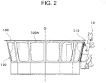
- the combination weighing apparatus 1 further includes: a driver 10 that drives the pool hoppers 60 and the weighing hoppers 70; and a main body 100 to be attached with the driver 10.
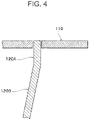
- the main body 100 includes: a top plate 110 having a plane in the horizontal direction; and a side surface 120 to be attached with the driver 10.
- the side surface 120 has a first surface 120A and a second surface 120B.
- the first surface 120A stands up in the vertical direction, and is connected to the top plate 110.
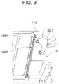
- the second surface 120B is connected continuously with the first surface 120A, is attached with the driver 10, and is inclined in a direction of going toward a center axis O (see FIG. 1 ) of the main body as going downward in the vertical direction.
- the second surface 120B is inclined as going downward in the vertical direction, and accordingly, adhered matter to the second surface 120B slides down or falls down along the second surface 120B. Therefore, hygiene in the combination weighing apparatus 1 can be improved.
- the second surface 120B is inclined as described above, whereby an attaching surface of the driver 10 can also be inclined. Therefore, an upper surface of the driver 10 can also be inclined in conjunction, and the article retained on this upper surface can be reduced.
- openings 100A are formed in the second surface 120B.
- the driver 10 is configured to be inserted into each of the openings 100A in a direction of going inward from the outside of the main body 100 and to be attached to the main body 100.
- both of the top plate 110 and the first surface 120A can be welded to each other to facilitate machining thereof, and cost can be reduced. Further, machining accuracy can also be improved.
- the driver 10 includes: a first motor 14 that drives the pool hopper 60; a second motor 13 that drives the weighing hopper 70; and a load cell 12 that senses the weight of the article stored in the weighing hopper 70.
- the first motor 14, the second motor 13 and the load cell 12 are arranged in a state of being arrayed in the up-down direction U/L.
- the second motor 13, the load cell 12 and the first motor 14 are arranged in a state of being arrayed in this order from the upper side U. That is, the second motor 13 is disposed more on the upper side U than the load cell 12, and the load cell 12 is disposed more on the upper side U than the first motor 14.
- At least a member to be disposed on a lowermost side L among the first motor 14, the second motor 13 and the load cell 12 is disposed to be offset to the inside I of the main body 100 with respect to other members.
- the first motor 14 is disposed to be offset to the inside I of the main body 100 with respect to the second motor 13 and the load cell 12.
- a height dimension of a component (internal component) of the driver 10, which is disposed more on the inside I than the opening 100A provided on the side surface of the main body 100, is larger than a height dimension of such an opening 100A. Therefore, the internal component is inserted into the opening 100A while inclining the driver 10 with respect to the opening 100A of the main body 100, whereby the driver 10 can be attached to the side surface of the main body 100.
- the height dimension of the opening 100A can be reduced, and accordingly, waterproofness thereof can be improved.
- the first motor 14 is not disposed immediately below the load cell 12, and therefore, the load cell 12 is less affected by heat generation of the first motor 14, and weighing accuracy can be improved.
- the present embodiment it is possible to makes it easy to join the top plate portion and the side surface to each other, and prevent the decrease of the machining accuracy due to the joining.
Landscapes
- Engineering & Computer Science (AREA)
- Mechanical Engineering (AREA)
- Physics & Mathematics (AREA)
- General Physics & Mathematics (AREA)
- Quality & Reliability (AREA)
- Filling Or Emptying Of Bunkers, Hoppers, And Tanks (AREA)
Applications Claiming Priority (1)
| Application Number | Priority Date | Filing Date | Title |
|---|---|---|---|
| JP2020185848A JP7597356B2 (ja) | 2020-11-06 | 2020-11-06 | 物品搬送装置 |
Publications (3)
| Publication Number | Publication Date |
|---|---|
| EP3995793A1 true EP3995793A1 (de) | 2022-05-11 |
| EP3995793C0 EP3995793C0 (de) | 2024-02-14 |
| EP3995793B1 EP3995793B1 (de) | 2024-02-14 |
Family
ID=78592454
Family Applications (1)
| Application Number | Title | Priority Date | Filing Date |
|---|---|---|---|
| EP21204289.9A Active EP3995793B1 (de) | 2020-11-06 | 2021-10-22 | Artikelfördervorrichtung |
Country Status (4)
| Country | Link |
|---|---|
| US (1) | US11932483B2 (de) |
| EP (1) | EP3995793B1 (de) |
| JP (1) | JP7597356B2 (de) |
| CN (1) | CN114441022B (de) |
Citations (2)
| Publication number | Priority date | Publication date | Assignee | Title |
|---|---|---|---|---|
| EP0852328A1 (de) * | 1996-07-03 | 1998-07-08 | ISHIDA CO., Ltd. | Messvorrichtung zur vereinfachung des montierens und auswechselns eines behälters |
| EP1228988B1 (de) * | 2000-03-17 | 2011-05-11 | Anritsu Industrial Solutions Co.,Ltd. | Kombinationswaage |
Family Cites Families (21)
| Publication number | Priority date | Publication date | Assignee | Title |
|---|---|---|---|---|
| JPS5846127U (ja) * | 1981-09-24 | 1983-03-28 | 株式会社石田衡器製作所 | ホツパ−の取付装置 |
| US5101954A (en) | 1989-12-15 | 1992-04-07 | Nambu Electric Co., Ltd. | Article conveying method and apparatus |
| JPH0826449A (ja) | 1994-07-11 | 1996-01-30 | Ceratec:Kk | 物品搬送装置と物品搬送方法と物品搬送処理装置と物品搬送処理方法と物品搬送システムと物品搬送処理システムと物品搬送装置用圧電駆動装置と物品搬送処理装置用圧電駆動装置 |
| JPH08114492A (ja) * | 1994-10-17 | 1996-05-07 | Ishida Co Ltd | 組合せ計量装置 |
| JP2000046635A (ja) * | 1998-07-27 | 2000-02-18 | Anritsu Corp | ホッパおよび組合せ計量装置 |
| JP2001330504A (ja) * | 2000-05-19 | 2001-11-30 | Anritsu Corp | 組合せ計量装置 |
| US6703568B2 (en) * | 2000-05-19 | 2004-03-09 | Anritsu Corporation | Combination weighing apparatus having a weighing device base, to which a plurality of weighing devices are fixed, that is directly fixed to a stand |
| JP4173412B2 (ja) * | 2003-08-06 | 2008-10-29 | 株式会社イシダ | 組合せ計量装置 |
| EP2634546B1 (de) * | 2010-10-29 | 2019-05-08 | Yamato Scale Co., Ltd. | Mehrkopfwaage |
| JP5858729B2 (ja) * | 2011-10-28 | 2016-02-10 | 大和製衡株式会社 | ホッパの開閉機構 |
| JP6242086B2 (ja) * | 2013-06-05 | 2017-12-06 | 大和製衡株式会社 | 組合せ秤 |
| JP6320067B2 (ja) * | 2014-02-13 | 2018-05-09 | 大和製衡株式会社 | ホッパ及びこれを備えた組合せ秤 |
| CN204548588U (zh) * | 2015-01-16 | 2015-08-12 | 上海禹通机械有限公司 | 一种适用于杆状物料的多色混装设备 |
| JP3197141U (ja) * | 2015-02-09 | 2015-04-23 | 株式会社イシダ | 組合せ計量装置 |
| JP6529828B2 (ja) * | 2015-06-10 | 2019-06-12 | 大和製衡株式会社 | 分散トレイ及びこれを備えた組合せ秤 |
| JP6465760B2 (ja) * | 2015-06-17 | 2019-02-06 | 大和製衡株式会社 | 組合せ秤 |
| JP6654480B2 (ja) * | 2016-03-18 | 2020-02-26 | 株式会社イシダ | 組合せ計量装置 |
| JP7009187B2 (ja) * | 2017-12-01 | 2022-01-25 | 大和製衡株式会社 | 物品規制装置及びこれを備えた組合せ秤 |
| JP2019124619A (ja) * | 2018-01-18 | 2019-07-25 | 大和製衡株式会社 | 組合せ秤 |
| CN110092159A (zh) | 2018-01-31 | 2019-08-06 | 山东新北洋信息技术股份有限公司 | 物品输送方法及设备 |
| JP7300706B2 (ja) * | 2019-03-12 | 2023-06-30 | 株式会社イシダ | 組合せ計量装置、及び組合せ計量装置用の架台 |
-
2020
- 2020-11-06 JP JP2020185848A patent/JP7597356B2/ja active Active
-
2021
- 2021-10-22 US US17/508,963 patent/US11932483B2/en active Active
- 2021-10-22 EP EP21204289.9A patent/EP3995793B1/de active Active
- 2021-10-29 CN CN202111277253.XA patent/CN114441022B/zh active Active
Patent Citations (3)
| Publication number | Priority date | Publication date | Assignee | Title |
|---|---|---|---|---|
| EP0852328A1 (de) * | 1996-07-03 | 1998-07-08 | ISHIDA CO., Ltd. | Messvorrichtung zur vereinfachung des montierens und auswechselns eines behälters |
| JP3670295B2 (ja) | 1996-07-03 | 2005-07-13 | 株式会社イシダ | ホッパの着脱性を改善した計量装置 |
| EP1228988B1 (de) * | 2000-03-17 | 2011-05-11 | Anritsu Industrial Solutions Co.,Ltd. | Kombinationswaage |
Also Published As
| Publication number | Publication date |
|---|---|
| JP2022075207A (ja) | 2022-05-18 |
| CN114441022B (zh) | 2025-04-01 |
| EP3995793C0 (de) | 2024-02-14 |
| JP7597356B2 (ja) | 2024-12-10 |
| EP3995793B1 (de) | 2024-02-14 |
| CN114441022A (zh) | 2022-05-06 |
| US20220144539A1 (en) | 2022-05-12 |
| US11932483B2 (en) | 2024-03-19 |
Similar Documents
| Publication | Publication Date | Title |
|---|---|---|
| US8525048B2 (en) | Combination weigher having improved combination hopper access | |
| EP3995793B1 (de) | Artikelfördervorrichtung | |
| US11333546B2 (en) | Combination weighing apparatus with improved hopper attachment workability | |
| US11927470B2 (en) | Combination weighing apparatus with discharge chute including slide surface | |
| CN113490628B (zh) | 物品停留装置以及支撑体 | |
| EP4246105B1 (de) | Kombinationswiegevorrichtung | |
| CN115121501B (zh) | 供料装置 | |
| WO2020122052A1 (ja) | 組合せ計量装置 | |
| JP2008239243A (ja) | 飼料供給タンク | |
| KR100846823B1 (ko) | 너트공급기 일체형 용접장치 | |
| US20220146302A1 (en) | Combination weighing apparatus | |
| CN217497787U (zh) | 一种自动分料装置 | |
| EP1511678A1 (de) | Träger und handhabungshilfe für flache postsachen | |
| CN219456984U (zh) | 一种组装教学设备 | |
| CN217497506U (zh) | 一种电机护磁圈自动分料装置 | |
| CN214494470U (zh) | 一种多用途螺丝供料机构及自动螺丝送料设备 | |
| US10690536B2 (en) | Multihead weigher and weighing method | |
| CN218193260U (zh) | 一种弹片端子焊接设备 | |
| CN210758658U (zh) | 一种塑料颗粒造粒称重喂料机 | |
| JP2021147052A (ja) | 包装機 | |
| EP4589268A1 (de) | Kombinationswiegevorrichtung | |
| CN215550163U (zh) | 适用于包装覆膜制造的投料设备 | |
| CN221115573U (zh) | 一种运行稳定的分拣输送装置 | |
| CN219301774U (zh) | 一种皮带机式组合秤 | |
| CN210653805U (zh) | 一种纸管包装机用的进料装置 |
Legal Events
| Date | Code | Title | Description |
|---|---|---|---|
| PUAI | Public reference made under article 153(3) epc to a published international application that has entered the european phase |
Free format text: ORIGINAL CODE: 0009012 |
|
| STAA | Information on the status of an ep patent application or granted ep patent |
Free format text: STATUS: REQUEST FOR EXAMINATION WAS MADE |
|
| 17P | Request for examination filed |
Effective date: 20211022 |
|
| AK | Designated contracting states |
Kind code of ref document: A1 Designated state(s): AL AT BE BG CH CY CZ DE DK EE ES FI FR GB GR HR HU IE IS IT LI LT LU LV MC MK MT NL NO PL PT RO RS SE SI SK SM TR |
|
| GRAP | Despatch of communication of intention to grant a patent |
Free format text: ORIGINAL CODE: EPIDOSNIGR1 |
|
| STAA | Information on the status of an ep patent application or granted ep patent |
Free format text: STATUS: GRANT OF PATENT IS INTENDED |
|
| INTG | Intention to grant announced |
Effective date: 20230905 |
|
| GRAS | Grant fee paid |
Free format text: ORIGINAL CODE: EPIDOSNIGR3 |
|
| GRAA | (expected) grant |
Free format text: ORIGINAL CODE: 0009210 |
|
| STAA | Information on the status of an ep patent application or granted ep patent |
Free format text: STATUS: THE PATENT HAS BEEN GRANTED |
|
| AK | Designated contracting states |
Kind code of ref document: B1 Designated state(s): AL AT BE BG CH CY CZ DE DK EE ES FI FR GB GR HR HU IE IS IT LI LT LU LV MC MK MT NL NO PL PT RO RS SE SI SK SM TR |
|
| REG | Reference to a national code |
Ref country code: GB Ref legal event code: FG4D |
|
| REG | Reference to a national code |
Ref country code: CH Ref legal event code: EP |
|
| REG | Reference to a national code |
Ref country code: DE Ref legal event code: R096 Ref document number: 602021009360 Country of ref document: DE |
|
| REG | Reference to a national code |
Ref country code: IE Ref legal event code: FG4D |
|
| U01 | Request for unitary effect filed |
Effective date: 20240223 |
|
| U07 | Unitary effect registered |
Designated state(s): AT BE BG DE DK EE FI FR IT LT LU LV MT NL PT SE SI Effective date: 20240301 |
|
| REG | Reference to a national code |
Ref country code: LT Ref legal event code: MG9D |
|
| PG25 | Lapsed in a contracting state [announced via postgrant information from national office to epo] |
Ref country code: IS Free format text: LAPSE BECAUSE OF FAILURE TO SUBMIT A TRANSLATION OF THE DESCRIPTION OR TO PAY THE FEE WITHIN THE PRESCRIBED TIME-LIMIT Effective date: 20240614 |
|
| PG25 | Lapsed in a contracting state [announced via postgrant information from national office to epo] |
Ref country code: GR Free format text: LAPSE BECAUSE OF FAILURE TO SUBMIT A TRANSLATION OF THE DESCRIPTION OR TO PAY THE FEE WITHIN THE PRESCRIBED TIME-LIMIT Effective date: 20240515 |
|
| PG25 | Lapsed in a contracting state [announced via postgrant information from national office to epo] |
Ref country code: HR Free format text: LAPSE BECAUSE OF FAILURE TO SUBMIT A TRANSLATION OF THE DESCRIPTION OR TO PAY THE FEE WITHIN THE PRESCRIBED TIME-LIMIT Effective date: 20240214 Ref country code: RS Free format text: LAPSE BECAUSE OF FAILURE TO SUBMIT A TRANSLATION OF THE DESCRIPTION OR TO PAY THE FEE WITHIN THE PRESCRIBED TIME-LIMIT Effective date: 20240514 |
|
| PG25 | Lapsed in a contracting state [announced via postgrant information from national office to epo] |
Ref country code: ES Free format text: LAPSE BECAUSE OF FAILURE TO SUBMIT A TRANSLATION OF THE DESCRIPTION OR TO PAY THE FEE WITHIN THE PRESCRIBED TIME-LIMIT Effective date: 20240214 |
|
| PG25 | Lapsed in a contracting state [announced via postgrant information from national office to epo] |
Ref country code: RS Free format text: LAPSE BECAUSE OF FAILURE TO SUBMIT A TRANSLATION OF THE DESCRIPTION OR TO PAY THE FEE WITHIN THE PRESCRIBED TIME-LIMIT Effective date: 20240514 Ref country code: NO Free format text: LAPSE BECAUSE OF FAILURE TO SUBMIT A TRANSLATION OF THE DESCRIPTION OR TO PAY THE FEE WITHIN THE PRESCRIBED TIME-LIMIT Effective date: 20240514 Ref country code: IS Free format text: LAPSE BECAUSE OF FAILURE TO SUBMIT A TRANSLATION OF THE DESCRIPTION OR TO PAY THE FEE WITHIN THE PRESCRIBED TIME-LIMIT Effective date: 20240614 Ref country code: HR Free format text: LAPSE BECAUSE OF FAILURE TO SUBMIT A TRANSLATION OF THE DESCRIPTION OR TO PAY THE FEE WITHIN THE PRESCRIBED TIME-LIMIT Effective date: 20240214 Ref country code: GR Free format text: LAPSE BECAUSE OF FAILURE TO SUBMIT A TRANSLATION OF THE DESCRIPTION OR TO PAY THE FEE WITHIN THE PRESCRIBED TIME-LIMIT Effective date: 20240515 Ref country code: ES Free format text: LAPSE BECAUSE OF FAILURE TO SUBMIT A TRANSLATION OF THE DESCRIPTION OR TO PAY THE FEE WITHIN THE PRESCRIBED TIME-LIMIT Effective date: 20240214 |
|
| PG25 | Lapsed in a contracting state [announced via postgrant information from national office to epo] |
Ref country code: PL Free format text: LAPSE BECAUSE OF FAILURE TO SUBMIT A TRANSLATION OF THE DESCRIPTION OR TO PAY THE FEE WITHIN THE PRESCRIBED TIME-LIMIT Effective date: 20240214 |
|
| PG25 | Lapsed in a contracting state [announced via postgrant information from national office to epo] |
Ref country code: PL Free format text: LAPSE BECAUSE OF FAILURE TO SUBMIT A TRANSLATION OF THE DESCRIPTION OR TO PAY THE FEE WITHIN THE PRESCRIBED TIME-LIMIT Effective date: 20240214 |
|
| PG25 | Lapsed in a contracting state [announced via postgrant information from national office to epo] |
Ref country code: SM Free format text: LAPSE BECAUSE OF FAILURE TO SUBMIT A TRANSLATION OF THE DESCRIPTION OR TO PAY THE FEE WITHIN THE PRESCRIBED TIME-LIMIT Effective date: 20240214 |
|
| PG25 | Lapsed in a contracting state [announced via postgrant information from national office to epo] |
Ref country code: CZ Free format text: LAPSE BECAUSE OF FAILURE TO SUBMIT A TRANSLATION OF THE DESCRIPTION OR TO PAY THE FEE WITHIN THE PRESCRIBED TIME-LIMIT Effective date: 20240214 |
|
| PG25 | Lapsed in a contracting state [announced via postgrant information from national office to epo] |
Ref country code: SK Free format text: LAPSE BECAUSE OF FAILURE TO SUBMIT A TRANSLATION OF THE DESCRIPTION OR TO PAY THE FEE WITHIN THE PRESCRIBED TIME-LIMIT Effective date: 20240214 |
|
| PG25 | Lapsed in a contracting state [announced via postgrant information from national office to epo] |
Ref country code: SM Free format text: LAPSE BECAUSE OF FAILURE TO SUBMIT A TRANSLATION OF THE DESCRIPTION OR TO PAY THE FEE WITHIN THE PRESCRIBED TIME-LIMIT Effective date: 20240214 Ref country code: SK Free format text: LAPSE BECAUSE OF FAILURE TO SUBMIT A TRANSLATION OF THE DESCRIPTION OR TO PAY THE FEE WITHIN THE PRESCRIBED TIME-LIMIT Effective date: 20240214 Ref country code: RO Free format text: LAPSE BECAUSE OF FAILURE TO SUBMIT A TRANSLATION OF THE DESCRIPTION OR TO PAY THE FEE WITHIN THE PRESCRIBED TIME-LIMIT Effective date: 20240214 Ref country code: CZ Free format text: LAPSE BECAUSE OF FAILURE TO SUBMIT A TRANSLATION OF THE DESCRIPTION OR TO PAY THE FEE WITHIN THE PRESCRIBED TIME-LIMIT Effective date: 20240214 |
|
| REG | Reference to a national code |
Ref country code: DE Ref legal event code: R097 Ref document number: 602021009360 Country of ref document: DE |
|
| U20 | Renewal fee for the european patent with unitary effect paid |
Year of fee payment: 4 Effective date: 20241028 |
|
| PLBE | No opposition filed within time limit |
Free format text: ORIGINAL CODE: 0009261 |
|
| STAA | Information on the status of an ep patent application or granted ep patent |
Free format text: STATUS: NO OPPOSITION FILED WITHIN TIME LIMIT |
|
| 26N | No opposition filed |
Effective date: 20241115 |
|
| REG | Reference to a national code |
Ref country code: CH Ref legal event code: PL |
|
| PG25 | Lapsed in a contracting state [announced via postgrant information from national office to epo] |
Ref country code: MC Free format text: LAPSE BECAUSE OF FAILURE TO SUBMIT A TRANSLATION OF THE DESCRIPTION OR TO PAY THE FEE WITHIN THE PRESCRIBED TIME-LIMIT Effective date: 20240214 |
|
| PG25 | Lapsed in a contracting state [announced via postgrant information from national office to epo] |
Ref country code: CH Free format text: LAPSE BECAUSE OF NON-PAYMENT OF DUE FEES Effective date: 20241031 |
|
| PG25 | Lapsed in a contracting state [announced via postgrant information from national office to epo] |
Ref country code: IE Free format text: LAPSE BECAUSE OF NON-PAYMENT OF DUE FEES Effective date: 20241022 |
|
| U20 | Renewal fee for the european patent with unitary effect paid |
Year of fee payment: 5 Effective date: 20251027 |
|
| PGFP | Annual fee paid to national office [announced via postgrant information from national office to epo] |
Ref country code: GB Payment date: 20251024 Year of fee payment: 5 |
|
| PG25 | Lapsed in a contracting state [announced via postgrant information from national office to epo] |
Ref country code: CY Free format text: LAPSE BECAUSE OF FAILURE TO SUBMIT A TRANSLATION OF THE DESCRIPTION OR TO PAY THE FEE WITHIN THE PRESCRIBED TIME-LIMIT; INVALID AB INITIO Effective date: 20211022 |
|
| PG25 | Lapsed in a contracting state [announced via postgrant information from national office to epo] |
Ref country code: HU Free format text: LAPSE BECAUSE OF FAILURE TO SUBMIT A TRANSLATION OF THE DESCRIPTION OR TO PAY THE FEE WITHIN THE PRESCRIBED TIME-LIMIT; INVALID AB INITIO Effective date: 20211022 |