EP3995986A1 - Formstück für ein flugzeug - Google Patents
Formstück für ein flugzeug Download PDFInfo
- Publication number
- EP3995986A1 EP3995986A1 EP20382969.2A EP20382969A EP3995986A1 EP 3995986 A1 EP3995986 A1 EP 3995986A1 EP 20382969 A EP20382969 A EP 20382969A EP 3995986 A1 EP3995986 A1 EP 3995986A1
- Authority
- EP
- European Patent Office
- Prior art keywords
- wall
- fitting
- lateral
- edge
- lateral edge
- Prior art date
- Legal status (The legal status is an assumption and is not a legal conclusion. Google has not performed a legal analysis and makes no representation as to the accuracy of the status listed.)
- Withdrawn
Links
Images





Classifications
-
- G—PHYSICS
- G06—COMPUTING OR CALCULATING; COUNTING
- G06F—ELECTRIC DIGITAL DATA PROCESSING
- G06F30/00—Computer-aided design [CAD]
- G06F30/20—Design optimisation, verification or simulation
- G06F30/23—Design optimisation, verification or simulation using finite element methods [FEM] or finite difference methods [FDM]
-
- B—PERFORMING OPERATIONS; TRANSPORTING
- B64—AIRCRAFT; AVIATION; COSMONAUTICS
- B64C—AEROPLANES; HELICOPTERS
- B64C1/00—Fuselages; Constructional features common to fuselages, wings, stabilising surfaces or the like
- B64C1/06—Frames; Stringers; Longerons ; Fuselage sections
-
- B—PERFORMING OPERATIONS; TRANSPORTING
- B33—ADDITIVE MANUFACTURING TECHNOLOGY
- B33Y—ADDITIVE MANUFACTURING, i.e. MANUFACTURING OF THREE-DIMENSIONAL [3D] OBJECTS BY ADDITIVE DEPOSITION, ADDITIVE AGGLOMERATION OR ADDITIVE LAYERING, e.g. BY 3D PRINTING, STEREOLITHOGRAPHY OR SELECTIVE LASER SINTERING
- B33Y50/00—Data acquisition or data processing for additive manufacturing
-
- B—PERFORMING OPERATIONS; TRANSPORTING
- B33—ADDITIVE MANUFACTURING TECHNOLOGY
- B33Y—ADDITIVE MANUFACTURING, i.e. MANUFACTURING OF THREE-DIMENSIONAL [3D] OBJECTS BY ADDITIVE DEPOSITION, ADDITIVE AGGLOMERATION OR ADDITIVE LAYERING, e.g. BY 3D PRINTING, STEREOLITHOGRAPHY OR SELECTIVE LASER SINTERING
- B33Y80/00—Products made by additive manufacturing
-
- B—PERFORMING OPERATIONS; TRANSPORTING
- B64—AIRCRAFT; AVIATION; COSMONAUTICS
- B64C—AEROPLANES; HELICOPTERS
- B64C1/00—Fuselages; Constructional features common to fuselages, wings, stabilising surfaces or the like
- B64C1/06—Frames; Stringers; Longerons ; Fuselage sections
- B64C1/068—Fuselage sections
- B64C1/0685—Tail cones
-
- B—PERFORMING OPERATIONS; TRANSPORTING
- B64—AIRCRAFT; AVIATION; COSMONAUTICS
- B64C—AEROPLANES; HELICOPTERS
- B64C1/00—Fuselages; Constructional features common to fuselages, wings, stabilising surfaces or the like
- B64C1/14—Windows; Doors; Hatch covers or access panels; Surrounding frame structures; Canopies; Windscreens accessories therefor, e.g. pressure sensors, water deflectors, hinges, seals, handles, latches, windscreen wipers
- B64C1/1407—Doors; surrounding frames
- B64C1/1415—Cargo doors, e.g. incorporating ramps
-
- B—PERFORMING OPERATIONS; TRANSPORTING
- B64—AIRCRAFT; AVIATION; COSMONAUTICS
- B64C—AEROPLANES; HELICOPTERS
- B64C1/00—Fuselages; Constructional features common to fuselages, wings, stabilising surfaces or the like
- B64C2001/0054—Fuselage structures substantially made from particular materials
- B64C2001/0072—Fuselage structures substantially made from particular materials from composite materials
-
- G—PHYSICS
- G06—COMPUTING OR CALCULATING; COUNTING
- G06F—ELECTRIC DIGITAL DATA PROCESSING
- G06F2113/00—Details relating to the application field
- G06F2113/10—Additive manufacturing, e.g. three-dimensional [3D] printing
-
- Y—GENERAL TAGGING OF NEW TECHNOLOGICAL DEVELOPMENTS; GENERAL TAGGING OF CROSS-SECTIONAL TECHNOLOGIES SPANNING OVER SEVERAL SECTIONS OF THE IPC; TECHNICAL SUBJECTS COVERED BY FORMER USPC CROSS-REFERENCE ART COLLECTIONS [XRACs] AND DIGESTS
- Y02—TECHNOLOGIES OR APPLICATIONS FOR MITIGATION OR ADAPTATION AGAINST CLIMATE CHANGE
- Y02T—CLIMATE CHANGE MITIGATION TECHNOLOGIES RELATED TO TRANSPORTATION
- Y02T50/00—Aeronautics or air transport
- Y02T50/40—Weight reduction
Definitions
- the present invention belongs to the technical field of structural reinforcements in an airframe and joints between structural parts of the airframe.
- the invention provides a structural fitting made of fused composite material manufactured by an additive manufacturing process.
- the invention belongs to the field of manufacturing methods for such fused structural fittings by means of Fused Composites Manufacturing based on computer-implemented 3D designs.
- said fittings can be used to reinforce structures or joints between elements forming an L-type geometry, that is, a geometry where part of a structure comprised essentially in a flat plane transitions to another structural plane having a certain angle with respect to the first one, by means of a curved 'transition' or 'hinging' area.
- these fittings may also take the form of local reinforcements of larger parts such as beams, longerons, frames, etc. thus acting as ribs to modify and alleviate in service the stresses that the part is subjected to at a specific point.
- fittings are subjected to very complex stress states where both tensile and shear loads are typically transmitted through them toward their connection areas with the airframe parts, making them in some circumstances undergoing high structural stresses.
- these fittings may also be known as clips in case the joining parts are much lighter than the common industrial parts and, then, do not impose structural severity.
- clips are used for holding cabling, wiring, or other minor auxiliary components to the primary structures for their routing.
- the structural fittings used traditionally in the aircraft industry as reinforcing elements for the aforementioned purposes are metallic machined shear-brackets. More in particular, shear-brackets made of titanium alloys in those cases wherein the fitting is subjected to extreme environmental conditions in service, such as corrosion or high temperature.
- the present invention provides a solution for the aforementioned problems, by a fused composite manufactured fitting according to claim 1.
- the invention also provides a method for manufacturing said fitting according to claim 15.
- Advantageous embodiments are defined in the dependent claims.
- the invention provides a fused composite manufactured fitting comprising:
- a fitting should be understood as a structural element intended for joining different parts and, therefore, it is provided with a first and a second substantially flat walls angled to each other and with respective securing areas. Accordingly, these securing areas may be provided with securing means such as holes suitable for receiving bolts, rivets, or other fastening means, or even adhesives for a satisfactory joining.
- these fittings may also be known as clips in case the secured parts are much lighter than the common industrial parts (e.g., frames, longerons, ribs, etc.) and, then, do not impose structural severity.
- clips are used for holding cabling, wiring, or other minor auxiliary components to the primary structures for their routing.
- CFRP Carbon Fibre Reinforced Polymers
- composite laminates as an essential element of the building up process of said airframe structural parts.
- Said laminates shall be “regarded” as multiple stacked plies, each one comprising reinforcement fibres impregnated within a resin matrix, such as in the form of a 'pre-preg'.
- These laminates may be pre-formed into particular shapes and then brought together to conform moderately complex shapes according to the design of the structural part.
- complex shapes such as corners
- the laminate thickness may deviate from the nominal thickness obtained for flat plates. This is due to two phenomena that occur in corners.
- additive Manufacturing also referred to as 3D printing
- additive Manufacturing also referred to as 3D printing
- 3D printing relates to current manufacturing methods and technologies wherein three-dimensional components are built up applying successive layers of material under computer control, departing from a digital model of the component to be produced.
- the material either meltable material or matrix material in the case of reinforced materials
- the digital CAD sketch of the fitting is digitally sliced into multiple horizontal sections or layers.
- the printer controller uses this generated slicing to manufacture the fitting sequentially, for instance with one layer at a time (i.e. layer-by-layer), with each layer adhering or bonding to the previous one.
- Additive Manufacturing technologies are encompassed within Additive Manufacturing technologies, depending on the form of the material and machine technology used.
- the fused composite fitting of the invention is manufactured using Additive Manufacturing technologies such as Fused Composites Manufacturing (FCM).
- FCM Fused Composites Manufacturing
- FCM is an additive manufacturing technology wherein a molten thermoplastic filament reinforced with fibrous reinforcement material (e.g., carbon, glass, aramid) is extruded through a nozzle that traces the surface pattern for each particular layer.
- fibrous reinforcement material e.g., carbon, glass, aramid
- the nozzle is responsible for keeping the plastic at a temperature just above its melting point so that it flows easily through the nozzle and forms the layer.
- the plastic solidifies immediately after application from the nozzle, thus bonding bonds to the layer below.
- Source material is thermoplastic filament reinforced with fibrous reinforcement material. Binding mechanism is thermal and activation energy is based on a heated extrusion nozzle.
- the filaments may be made of ABS (Acrylonitrile butadiene styrene), PA (Polyamide), PC (Polycarbonate), PPSU (Polyphenyl sulfone), PEI (Polyetherimide), PEEK (Polyether ether ketone), PEKK (Polyetherketoneketone) or any other high performance thermoplastic material.
- ABS Acrylonitrile butadiene styrene
- PA Polyamide
- PC Polycarbonate
- PPSU Polyphenyl sulfone
- PEI Polyetherimide
- PEEK Polyether ether ketone
- PEKK Polyetherketoneketone
- the thermoplastic material is of any of the following: PEKK, PPS, PAEK, or PEEK. More preferably, the thermoplastic material is PAEK or PEEK. Most preferably the thermoplastic material is PEEK or PPS.
- the fibrous material reinforcement may be in the form of fibrils (very short and/or irregular fibres), nanofibers, carbon fillers, short fibres (length ⁇ 1mm), or continuous fibres (extended continuously along the whole filament and thus along the whole length/width of the filler when manufactured), for instance.
- the fibrous material reinforcement is in the form of continuous fibres and/or short-fibres, wherein continuous fibres are preferred.
- the fused composite fittings can be modelled by a 3D modelling software (Computer Aided Design or CAD), the CAD sketch (i.e. the 3D electronic model) can be dimensionally closer to the final area intended to be fixed to. Also, because the printed parts have little deviation with respect to the 3D sketch, the resulting fused composite manufactured fitting is proximate to the original connection area space and is thus better fixed thereto.
- CAD Computer Aided Design
- transition or hinging area that is, the corner or curved zone where a portion of the fitting comprised in a structural plane progresses to a different plane, can be accurately tuned and shaped with the desired geometry so as to continuously and smoothly connect to the airframe (i.e., the part of the frame/connection between parts that the fitting will reinforce).
- said continuous and homogeneous connection between the fused composite manufactured fitting and the aircraft achieved by the first and second substantially flat walls, along with the transition area, results in optimal load transmission through the connection area between the aircraft and the fused composite manufactured fitting, thus contributing to improve the local unfolding behaviour.
- the fused composite manufactured fitting can be provided directly on the connection area of the airframe to be reinforced, or, otherwise, it can be produced independently and at a later stage be fixed by means of a bolted joint or by adhesives.
- the advantage of printing the fused composite fittings by successive addition of material reduces the buy-to-fly ratio, i.e. the ratio between mass of material that is required to produce a part and the mass of material in the finished aeronautical structure.
- the solution proposed by the invention is an alternative that allows the recycling of a great portion of the final product obtained. Additionally, the production of the proposed fused composite material fittings using Additive Manufacturing technique increases the operational capacity, due to the greater flexibility it offers, both for the patterning of designs adapted to complex geometries and the ease and lower cost of resources for the production thereof.
- Titanium alloys are stronger than composites, but composites are lighter (around 1/3 of its density) than Ti-alloys, so larger fittings may be envisaged with the present invention to fulfil these structural requirements without impacting or even providing savings in the total weight.
- Larger it is referred to the thickness, the total area contacting the reinforced part or higher bending radius to avoid sharp angles in the deposited filaments weakening the curved transition areas.
- filament orientation during manufacturing may provide a strength surplus thank to the anisotropy of the resulting printed fitting.
- At least one of the lateral edges is substantially perpendicular to the longitudinal axis of the curved transition area.
- At least one of the first and second distal edges is oblique to the longitudinal axis of the curved transition area.
- At least one of the lateral edges is oblique to the longitudinal axis of the curved transition area.
- the fused composite manufactured fitting comprises third wall comprising a first edge and a second edge, the third wall being integrally merged with the first and second walls, such that:
- the closed cross-sectional shape of the fitting provides increased mechanical strength, which results in an improved load transmission through the connection area between the aircraft and the fused composite manufactured fitting, and thus to a better unfolding behaviour.
- tubular cross-sectional shape provide excellent properties with regard to loading in compression and bending in all directions and, moreover, is an effective configuration for resisting torsional moments.
- tubular structures provide a great strength to weight ratio, as well as both great torsional stiffness and compressive strength.
- the third wall which closes the cross-sectional shape of the fitting being integrally merged with the first and second wall, works in tension, thus contributing to reducing the local forces caused by the undesired unfolding effect.
- the 'unfolding' consist in a typical failure mode of composite laminates, wherein delamination occurs in both highly-curved and moderately-curved oriented-fibre composite laminates because said curvature induces interlaminar stresses as a result of an opening bending moment.
- the third wall is integrally merged with the first and second walls by means of respective curved transition or hinging areas.
- the fused composite manufactured fitting comprises a plurality of separate third walls arranged along the first distal edge of the first wall and the second distal edge of the second wall.
- more than one bar-type element may be necessary to promote tension over shear stresses.
- physically separating the third walls provides voids or lack of material for weight optimization. This weight reduction may be determined by a prior computer-implemented topologic optimization in order not to be detrimental for the structural behavior.
- At least one third wall is either a curved wall with a concave geometry or a substantially flat third wall.
- concave in this context, refers to the shape that curves inward when regarded from a reference internal to the fused composite manufactured fitting.
- the present feature should be construed as convex when considered from a reference external to the fused composite manufactured fitting.
- At least one third wall is provided with at least one lightening hole.
- the fused composite manufactured fitting can be provided with lightening holes which allow reducing the amount of raw material used.
- these lightening holes provide a hollow space that allows insertion of elements such as wires, while also providing better cooling features by means of an increase in the surface in contact with the surrounding airfield, especially in those areas exposed to extreme environmental conditions.
- the fused composite fabrication only provides the indispensable filaments to build in situ the fitting with the final geometry without any post-processing. Thus, savings in raw material consumption are envisaged.
- the fused composite manufactured fitting comprises at least one lateral reinforcing wall comprising a first lateral edge and a second lateral edge, the lateral reinforcing wall being integrally merged with at least the first wall by means of a fourth curved transition area, such that:
- any of the lateral reinforcing walls is also aiming at avoiding a pure bending moment (i.e., shear stresses) on the fitting that may jeopardize its integrity in service.
- the fourth curved transition area is shaped as a pipe elbow section, and wherein the lateral reinforcing wall is further integrally merged with the second wall by means of the fourth curved transition area, such that:
- the pipe elbow section may comprise a 90° elbow, or higher. This embodiment is of special interest for local reinforcement.
- the fused composite manufactured fitting comprises two lateral reinforcing walls integrally merged with the first and the second walls respectively by means of two respective fourth curved transition areas, wherein the fitting further comprises an upper reinforcing wall comprising a first lateral edge and a second lateral edge, the upper curved reinforcing wall being integrally merged with the two reinforcing walls by means of two respective fifth curved transition areas shaped as a pipe elbow section, such that:
- the fused composite manufactured fitting comprises a front (or outermost ) reinforcing wall comprising a proximal edge and a first lateral edge and a second lateral edge, the front reinforcing wall being integrally merged:
- the curved hollow beam shape of the fitting further comprises a funneled section protruding from the distal end of the curved hollow beam shape of the fitting towards a distal end of the fitting, and wherein the funneled section comprises:
- this embodiment provides the male or female part in form of a goose neck of the tongue and groove joint to be secured to a respective female or male lug.
- This connection is of special application for holding the compartment door of the aircraft tailcone.
- the fitting comprises the groove, it is represented a female part wherein the lug of the counterpart is intended to be placed therein and attached by bolting through the coaxial through-holes.
- this fitting represents a male part whose funneled section in configured to be positioned between a dual lug (acting as the female part).
- the funneled section narrows as it protrudes toward the distal end of the fitting in order to be accommodated between the lugs of the dual lug components to be bolted thereto.
- the options of this embodiment allows the fitting to be secured either to a single lug component or a dual lug component.
- the curved hollow beam shape may be infilled by injection molding of neat plastic, foam, or any other suitable polymeric infilling.
- the curved hollow beam shape comprises a polymeric infilling.
- this fitting is stronger than a non-filled embodiment, so the failure requirements are less restrictive. That is, in a degraded mode where one female fitting failed, the remainder infilled fittings may still allow to operate the tailcone door properly.
- the invention provides a method for manufacturing a fitting according to any of the embodiments of the first inventive aspect by Fused Composite Manufacturing techniques and intended to secure parts of an aircraft by means of securing areas, wherein the method comprises: determining a 3D design of the fitting by the following steps:
- a fitting is a structural element intended for joining different angled elements and, therefore, it is provided with a first and a second substantially flat walls with respective securing areas. These securing areas may be provided with holes to be bolted, riveted, or fastened to the secured parts. Likewise, industrial adhesives may accomplish a satisfactory joining.
- FEM models are numerical methods that allows to perform a structural analysis of a meshed and populated 3D design.
- the structural behavior under a set of external forces can be simulated and local stress concentrations properly identified.
- the 3D design represented by the populated mesh with the desired properties
- the fitting according to the invention should account for two main aspects: an appropriate 3D design, and the deposition path of the fibrous material reinforcement embedded within meltable material to build that shape.
- the local stress concentrations to be calculated for the final design of the fitting are interlaminar tensile strength (ILTS) and/or the interlaminar shear strength (ILSS).
- ILTS interlaminar tensile strength
- ILSS interlaminar shear strength
- 3D parts can be built with fibre oriented along the direction of the loads in order to effectively transmit them. Therefore, in an embodiment, a single filament may be contained within a wall of the fitting or may go beyond toward the curved transition area toward other wall.
- the step of topologically modifying the 3D design further comprises:
- the step of topologically modifying the 3D design by gradually providing reinforcing walls protruding beyond at least one edge of the 3D design further comprises:
- Figure 1 depicts a fused composite manufactured fitting (10) configured to be fixed and, thus, for reinforcing a local part of the airframe or for serving as a connection between parts in the aircraft.
- the connection area of the part of the aircraft to which the fitting (10) will be fixed comprises a corner, i.e., a highly curved portion. That is, the connection area will have two different surfaces, comprised in two respective planes which are oblique to each other, connected by means of a curved transition or hinging area.
- the fused composite manufactured fitting (10) shown comprises two substantially flat walls (11, 12) intended for being fixed respectively to both surfaces of the aircraft, as well as to said curved transition of hinging area.
- the fitting (10) shown comprises a first substantially flat wall (11) which, in turn, comprises a first proximal edge (11.0) and a first distal edge (11.1), and a first and a second lateral edges (11.2, 11.3).
- the second substantially flat wall (12) comprises a second proximal edge (12.0) and a second distal edge (12.1), and a third and a fourth lateral edges (12.2, 12.3).
- Both first (11) and second (12) substantially flat walls are integrally merged through each respective first (11.0) and second (12.0) proximal edges by a first curved transition area (13), which is shaped as a cylindrical segment.
- the fitting (10) is configured to be fixed to two perpendicular surfaces, and so the first and second substantially flat walls (11, 12) are both parallel to a longitudinal axis of the first curved transition area (13).
- Figure 2 represents the fused composite manufactured fitting (10) of figure 1 , wherein a plurality of separate third walls (14) have been provided, arranged along the first distal edge (11.1) of the first wall (11) and the second distal edge (12.2) of the second wall (12), for improving the mechanical properties of the fitting (10).
- the fitting (10) is shaped with a hollow beam geometry lengthwise (i.e., with a tubular cross-sectional shape), which results in an improved behaviour due to a higher strength to weight ratio, as well as both great torsional stiffness and compressive strength.
- each of the plurality of third walls (14) works in tension by virtue of the optimal load distribution of the hollow beam shape, thus contributing to reducing the local forces due to unfolding.
- Each of the third walls (14) is integrally merged with the first and second walls (11, 12) by means of a respective first edge (14.1) and a second edge (14.2).
- the third walls (14) are integrally merged with the first and second walls (11, 12) by means of respective curved transition or hinging areas.
- each third wall (14) are integrally merged with a portion of the first distal edge (11.1) of the first wall (11) by means of a second curved transition area (15) shaped as a cylindrical segment; and the second edges (14.2) of each third wall (14) are integrally merged with a portion of the second distal edge (12.2) of the second wall (12) by means of a third curved transition area (16) shaped as a cylindrical segment.
- Figure 3 depicts a fused composite manufactured fitting (10) having a shape adapted for allowing the fitting (10) to be fixed to a surface of the aircraft which comprises a highly curved corner, and a complex geometry.
- the first wall (11) which is comprised in a vertical plane according to the provided view of figure 3 , has a wedge-like shape. That is, in the embodiment shown, the first distal edge (11.1) of the first wall (11), is not parallel to the longitudinal axis of the curved transition area (13). Instead, it is now arranged oblique with respect to said curved transition area (13) to allow accommodating and fixing the fused composite material fitting (13) onto the connection area of the aircraft.
- the fitting (10) shown comprises one lateral reinforcing wall (17) configured to reinforce the mechanical behaviour of the fitting (10), in such a way that, in addition to providing directional reinforcement to support the local loads transmitted through the fitting (10), provides an additional connection area with a surface of the aircraft.
- Said reinforcing wall (17) comprises a first lateral edge (17.1) and a second lateral edge (17).
- said reinforcing wall (17) is integrally merged with the first wall (11) by means of a fourth curved transition area (18), such that the first lateral edge (17.1) of the lateral reinforcing wall (17) is integrally merged with the first lateral edge (11.2) of the first wall (11).
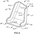
- Figure 4 represents the fused composite manufactured fitting (10) of figure 3 , wherein the fourth curved transition area (18) is shaped as a pipe elbow section, and wherein the lateral reinforcing wall (17) is extended so as to be further integrally merged with the second wall (12) as well as with the first wall (11).
- both the fourth curved transition area (18) and the first lateral edge (17.1) of the lateral reinforcing wall (17) are extended so as to be also integrally merged with the third lateral edge (12.2) of the second wall (12).
- the fitting (10) is provided with improved structural continuity, which results in a better load transmission therethrough.
- an additional reinforcing wall (17') has been provided.
- the additional reinforcing wall (17') comprises a first lateral edge (17,1') and a second lateral edge (17.2') and is integrally merged with the first and second walls (11, 12) in the very same manner than the first reinforcing wall (17) by means of an additional fourth curved transition area (18') shaped as a pipe elbow section.
- first lateral edge (17.1') of the additional reinforcing wall (17') is integrally merged with the second (11.3) and fourth lateral edges (12.3) of the second wall (12) by means of said additional fourth curved transition area (18').
- Figure 5 depicts the fused composite manufactured fitting (10) of figure 4 , modified so as to comprise a curved hollow beam shape lengthwise, or, in other words, a tubular configuration.
- the fitting (10) shown comprises an upper reinforcing wall (19) which is integrally merged with the rest of the elements of the fitting (10) so as to close the cross-sectional shape and achieve said hollow beam configuration.
- the upper reinforcing wall comprises a first lateral edge (19.1) and a second lateral edge (19.2), each of them being integrally merged respectively with the two reinforcing walls (17, 17') by means of two respective fifth curved transition areas (20, 20') shaped as pipe elbow sections.
- the first lateral edge (19.1) of the upper curved reinforcing wall (19) is integrally merged with the second lateral edge (17.2) of one lateral reinforcing wall (17) by means of one fifth curved transition area (20).
- the second lateral edge (19.2) of the upper curved reinforcing wall (19) is integrally merged with the second lateral edge (17.2') of the other lateral reinforcing wall (17') by means of the other fifth curved transition area (20').
- Figure 6 represents the fused composite manufactured fitting (10) of figure 3 , wherein an outermost reinforcing wall (21) has been provided.
- Said outermost reinforcing wall (21) comprises a proximal edge (21.1) and a first lateral edge (21.2) and a second lateral edge (21.3).
- the front reinforcing wall (21) is integrally merged with the second wall (12) by means of a sixth curved transition area (22).
- the front reinforcing wall (21) is also integrally merged with the lateral reinforcing wall (17) by means of a seventh curved transition area (23), such that the proximal edge (21.1) of the front reinforcing wall (21) is integrally merged with the second distal edge (12.1) of the second wall (12); and the first lateral edge (21.2) of the front reinforcing wall (21) is integrally merged with the second lateral edge (17.2) of the lateral reinforcing wall (17).
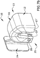
- Figure 7a depicts a fused composite manufactured fitting (10) comprising a curved hollow beam shape lengthwise, comprising a distal end (10.1) and a proximal end (10.2).
- the fitting (10) further comprises a funneled section (24) protruding from the distal end (10.1) of the curved hollow beam shape of the fitting (10) towards a distal end (25) of the fitting (10).
- Said funneled section (24) comprises two coaxial through-holes (26, 26') at opposite walls of the funneled section (24) configured for fixing the fitting (10) to a male structure of an aircraft by means of a hole/shaft basis joint.
- the funneled section (24) also comprises a groove (27) along a length of the funneled section (24) towards the distal end (25) of the fitting (10), the groove (27) being configured for fixing the fitting (10) to a male structure of an aircraft by means of a tongue and groove joint.
- FIG 7b it is depicted said female fitting (10) connected to a single male lug typically used for hanging an access door of the tailcone of the aircraft. It can be seen that the groove (27) is configured to receive the lug therein.
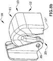
- Figure 8a depicts a fitting (10) similar to that of figure 7a , but without the groove (27) on the funneled section (24) as it should act as a male fitting (10) intended to be connected to a dual lug component.
- the funneled section (24) narrows as it protrudes toward the distal end (10.1) of the fitting (10) in order to be accommodated between the lugs of the dual lug components to be bolted thereto.
- the bolts provide a hinge line for pivoting the door between an open position and a closed position.
- the female fitting (10) of figure 7a may be designed so as to accommodate a male fitting (10) according to figure 8a .
- the groove (27) may allow the insertion of the thinner funneled section (24) of the male fitting (10), while the four through-holes (26, 26') must be coaxial in order to allow the insertion of the hinging bolt.
Landscapes
- Engineering & Computer Science (AREA)
- Mechanical Engineering (AREA)
- Aviation & Aerospace Engineering (AREA)
- Physics & Mathematics (AREA)
- Theoretical Computer Science (AREA)
- Computer Hardware Design (AREA)
- Evolutionary Computation (AREA)
- Geometry (AREA)
- General Engineering & Computer Science (AREA)
- General Physics & Mathematics (AREA)
- Connection Of Plates (AREA)
Priority Applications (2)
| Application Number | Priority Date | Filing Date | Title |
|---|---|---|---|
| EP20382969.2A EP3995986A1 (de) | 2020-11-10 | 2020-11-10 | Formstück für ein flugzeug |
| ES202132201U ES1286360Y (es) | 2020-11-10 | 2021-11-08 | Fijación para una aeronave |
Applications Claiming Priority (1)
| Application Number | Priority Date | Filing Date | Title |
|---|---|---|---|
| EP20382969.2A EP3995986A1 (de) | 2020-11-10 | 2020-11-10 | Formstück für ein flugzeug |
Publications (1)
| Publication Number | Publication Date |
|---|---|
| EP3995986A1 true EP3995986A1 (de) | 2022-05-11 |
Family
ID=73642800
Family Applications (1)
| Application Number | Title | Priority Date | Filing Date |
|---|---|---|---|
| EP20382969.2A Withdrawn EP3995986A1 (de) | 2020-11-10 | 2020-11-10 | Formstück für ein flugzeug |
Country Status (2)
| Country | Link |
|---|---|
| EP (1) | EP3995986A1 (de) |
| ES (1) | ES1286360Y (de) |
Citations (3)
| Publication number | Priority date | Publication date | Assignee | Title |
|---|---|---|---|---|
| US20090200425A1 (en) * | 2006-10-03 | 2009-08-13 | Risto Kallinen | Fitting |
| US8376275B2 (en) * | 2006-12-08 | 2013-02-19 | The Boeing Company | Energy absorbing structure for aircraft |
| US20170050677A1 (en) * | 2014-07-02 | 2017-02-23 | Divergent Technologies, Inc. | Systems and methods for vehicle subassembly and fabrication |
-
2020
- 2020-11-10 EP EP20382969.2A patent/EP3995986A1/de not_active Withdrawn
-
2021
- 2021-11-08 ES ES202132201U patent/ES1286360Y/es not_active Expired - Fee Related
Patent Citations (3)
| Publication number | Priority date | Publication date | Assignee | Title |
|---|---|---|---|---|
| US20090200425A1 (en) * | 2006-10-03 | 2009-08-13 | Risto Kallinen | Fitting |
| US8376275B2 (en) * | 2006-12-08 | 2013-02-19 | The Boeing Company | Energy absorbing structure for aircraft |
| US20170050677A1 (en) * | 2014-07-02 | 2017-02-23 | Divergent Technologies, Inc. | Systems and methods for vehicle subassembly and fabrication |
Non-Patent Citations (7)
| Title |
|---|
| JANTOS DUSTIN R ET AL: "Topology optimization with anisotropic materials, including a filter to smooth fiber pathways", STRUCTURAL AND MULTIDISCIPLINARY OPTIMIZATION, SPRINGER BERLIN HEIDELBERG, BERLIN/HEIDELBERG, vol. 61, no. 5, 14 February 2020 (2020-02-14), pages 2135 - 2154, XP037177220, ISSN: 1615-147X, [retrieved on 20200214], DOI: 10.1007/S00158-019-02461-X * |
| LEVY MIKE: "Is Polygon's Square One EX9 the Elusive 'One Bike'? - Review - Pinkbike", 19 July 2017 (2017-07-19), pages 1 - 49, XP055797090, Retrieved from the Internet <URL:https://www.pinkbike.com/news/polygon-square-one-ex9-review-2017.html> [retrieved on 20210420] * |
| LEWIS JENNIFER: "Novel 3D printing technique yields high- performance composites Arranging fibers just like nature does it", 15 January 2018 (2018-01-15), pages 1 - 6, XP055797489, Retrieved from the Internet <URL:https://www.seas.harvard.edu/news/2018/01/novel-3d-printing-technique-yields-high-performance-composites> [retrieved on 20210421] * |
| LIU JIKAI ET AL: "Light-weight shape and topology optimization with hybrid deposition path planning for FDM parts", THE INTERNATIONAL JOURNAL OF ADVANCED MANUFACTURING TECHNOLOGY, SPRINGER, LONDON, vol. 97, no. 1, 20 April 2018 (2018-04-20), pages 1123 - 1135, XP036528250, ISSN: 0268-3768, [retrieved on 20180420], DOI: 10.1007/S00170-018-1955-4 * |
| SLOAN JEF: "Carbon fiber meets simulation in ultralight bike frame", 8 April 2016 (2016-04-08), pages 1 - 11, XP055797192, Retrieved from the Internet <URL:https://www.compositesworld.com/articles/carbon-fiber-meets-simulation-in-ultralight-bike-frame> [retrieved on 20210420] * |
| SUN WEI ET AL: "Analysis of torsional failure and bearing capacity of composite thin-walled tubes filled with plastic foam", 2016 7TH INTERNATIONAL CONFERENCE ON MECHANICAL AND AEROSPACE ENGINEERING (ICMAE), IEEE, 18 July 2016 (2016-07-18), pages 17 - 22, XP032949625, DOI: 10.1109/ICMAE.2016.7549501 * |
| UNKNOWN: "2019 Newest Carbon Tubes Triangle Shaped Profile - Tstar Composites Co.,Ltd.", 31 December 2019 (2019-12-31), pages 1 - 9, XP055797038, Retrieved from the Internet <URL:https://www.tstarco.com/2019-newest-carbon-tubes-triangle-shaped-profile-2.html> [retrieved on 20210420] * |
Also Published As
| Publication number | Publication date |
|---|---|
| ES1286360U (es) | 2022-02-09 |
| ES1286360Y (es) | 2022-05-09 |
Similar Documents
| Publication | Publication Date | Title |
|---|---|---|
| US10744722B2 (en) | Radius filler for composite structure | |
| RU2636494C2 (ru) | Композитные радиусные заполнители и способы их изготовления | |
| US6375120B1 (en) | Method and apparatus for building a metal/composite hybrid airplane component | |
| CN109383048B (zh) | 用于增加飞机结构部件的强度和韧性的方法和装置 | |
| US11225015B2 (en) | Method for manufacturing an aeronautical structure | |
| CA2663151C (en) | Rib post | |
| US8418963B2 (en) | Aircraft load frame made of a composite material | |
| CA2726594C (en) | Aircraft fuselage frame in composite material with stabilized web | |
| EP1261787A2 (de) | Mehrschichtige verbundeckfüllungen | |
| US11358345B2 (en) | Internal tooling for composite parts | |
| US11697251B2 (en) | Joining method and assembly for an aircraft | |
| EP1801428B1 (de) | Metallische lokale Verstärkung für hochbelastete Verbindungen von Verbundbauteilen | |
| WO2018211232A1 (en) | Stiffening structure for an aircraft door or panel | |
| EP3625122B1 (de) | Türrahmen für ein fahrzeug | |
| US20200086550A1 (en) | Fastenerless structural assembly | |
| GB2564753A (en) | Fastenerless structural assembly | |
| ES1286360U (es) | Fijación para una aeronave | |
| WO2019219662A1 (en) | Composite joint |
Legal Events
| Date | Code | Title | Description |
|---|---|---|---|
| PUAI | Public reference made under article 153(3) epc to a published international application that has entered the european phase |
Free format text: ORIGINAL CODE: 0009012 |
|
| STAA | Information on the status of an ep patent application or granted ep patent |
Free format text: STATUS: THE APPLICATION HAS BEEN PUBLISHED |
|
| AK | Designated contracting states |
Kind code of ref document: A1 Designated state(s): AL AT BE BG CH CY CZ DE DK EE ES FI FR GB GR HR HU IE IS IT LI LT LU LV MC MK MT NL NO PL PT RO RS SE SI SK SM TR |
|
| STAA | Information on the status of an ep patent application or granted ep patent |
Free format text: STATUS: THE APPLICATION IS DEEMED TO BE WITHDRAWN |
|
| 18D | Application deemed to be withdrawn |
Effective date: 20221112 |