EP3996207B1 - Collier de serrage de mise à la terre à protection contre la rotation - Google Patents
Collier de serrage de mise à la terre à protection contre la rotation Download PDFInfo
- Publication number
- EP3996207B1 EP3996207B1 EP21205022.3A EP21205022A EP3996207B1 EP 3996207 B1 EP3996207 B1 EP 3996207B1 EP 21205022 A EP21205022 A EP 21205022A EP 3996207 B1 EP3996207 B1 EP 3996207B1
- Authority
- EP
- European Patent Office
- Prior art keywords
- cable
- plate
- opening
- transverse edge
- fastening
- Prior art date
- Legal status (The legal status is an assumption and is not a legal conclusion. Google has not performed a legal analysis and makes no representation as to the accuracy of the status listed.)
- Active
Links
Images



Classifications
-
- H—ELECTRICITY
- H01—ELECTRIC ELEMENTS
- H01R—ELECTRICALLY-CONDUCTIVE CONNECTIONS; STRUCTURAL ASSOCIATIONS OF A PLURALITY OF MUTUALLY-INSULATED ELECTRICAL CONNECTING ELEMENTS; COUPLING DEVICES; CURRENT COLLECTORS
- H01R11/00—Individual connecting elements providing two or more spaced connecting locations for conductive members which are, or may be, thereby interconnected, e.g. end pieces for wires or cables supported by the wire or cable and having means for facilitating electrical connection to some other wire, terminal, or conductive member, blocks of binding posts
- H01R11/11—End pieces or tapping pieces for wires, supported by the wire and for facilitating electrical connection to some other wire, terminal or conductive member
- H01R11/12—End pieces terminating in an eye, hook, or fork
- H01R11/14—End pieces terminating in an eye, hook, or fork the hook being adapted for hanging on overhead or other suspended lines, e.g. hot line clamp
-
- H—ELECTRICITY
- H01—ELECTRIC ELEMENTS
- H01R—ELECTRICALLY-CONDUCTIVE CONNECTIONS; STRUCTURAL ASSOCIATIONS OF A PLURALITY OF MUTUALLY-INSULATED ELECTRICAL CONNECTING ELEMENTS; COUPLING DEVICES; CURRENT COLLECTORS
- H01R4/00—Electrically-conductive connections between two or more conductive members in direct contact, i.e. touching one another; Means for effecting or maintaining such contact; Electrically-conductive connections having two or more spaced connecting locations for conductors and using contact members penetrating insulation
- H01R4/10—Electrically-conductive connections between two or more conductive members in direct contact, i.e. touching one another; Means for effecting or maintaining such contact; Electrically-conductive connections having two or more spaced connecting locations for conductors and using contact members penetrating insulation effected solely by twisting, wrapping, bending, crimping, or other permanent deformation
- H01R4/18—Electrically-conductive connections between two or more conductive members in direct contact, i.e. touching one another; Means for effecting or maintaining such contact; Electrically-conductive connections having two or more spaced connecting locations for conductors and using contact members penetrating insulation effected solely by twisting, wrapping, bending, crimping, or other permanent deformation by crimping
- H01R4/183—Electrically-conductive connections between two or more conductive members in direct contact, i.e. touching one another; Means for effecting or maintaining such contact; Electrically-conductive connections having two or more spaced connecting locations for conductors and using contact members penetrating insulation effected solely by twisting, wrapping, bending, crimping, or other permanent deformation by crimping for cylindrical elongated bodies, e.g. cables having circular cross-section
- H01R4/184—Electrically-conductive connections between two or more conductive members in direct contact, i.e. touching one another; Means for effecting or maintaining such contact; Electrically-conductive connections having two or more spaced connecting locations for conductors and using contact members penetrating insulation effected solely by twisting, wrapping, bending, crimping, or other permanent deformation by crimping for cylindrical elongated bodies, e.g. cables having circular cross-section comprising a U-shaped wire-receiving portion
-
- H—ELECTRICITY
- H01—ELECTRIC ELEMENTS
- H01R—ELECTRICALLY-CONDUCTIVE CONNECTIONS; STRUCTURAL ASSOCIATIONS OF A PLURALITY OF MUTUALLY-INSULATED ELECTRICAL CONNECTING ELEMENTS; COUPLING DEVICES; CURRENT COLLECTORS
- H01R4/00—Electrically-conductive connections between two or more conductive members in direct contact, i.e. touching one another; Means for effecting or maintaining such contact; Electrically-conductive connections having two or more spaced connecting locations for conductors and using contact members penetrating insulation
- H01R4/58—Electrically-conductive connections between two or more conductive members in direct contact, i.e. touching one another; Means for effecting or maintaining such contact; Electrically-conductive connections having two or more spaced connecting locations for conductors and using contact members penetrating insulation characterised by the form or material of the contacting members
- H01R4/64—Connections between or with conductive parts having primarily a non-electric function, e.g. frame, casing, rail
-
- H—ELECTRICITY
- H01—ELECTRIC ELEMENTS
- H01R—ELECTRICALLY-CONDUCTIVE CONNECTIONS; STRUCTURAL ASSOCIATIONS OF A PLURALITY OF MUTUALLY-INSULATED ELECTRICAL CONNECTING ELEMENTS; COUPLING DEVICES; CURRENT COLLECTORS
- H01R11/00—Individual connecting elements providing two or more spaced connecting locations for conductive members which are, or may be, thereby interconnected, e.g. end pieces for wires or cables supported by the wire or cable and having means for facilitating electrical connection to some other wire, terminal, or conductive member, blocks of binding posts
- H01R11/03—Individual connecting elements providing two or more spaced connecting locations for conductive members which are, or may be, thereby interconnected, e.g. end pieces for wires or cables supported by the wire or cable and having means for facilitating electrical connection to some other wire, terminal, or conductive member, blocks of binding posts characterised by the relationship between the connecting locations
- H01R11/09—Individual connecting elements providing two or more spaced connecting locations for conductive members which are, or may be, thereby interconnected, e.g. end pieces for wires or cables supported by the wire or cable and having means for facilitating electrical connection to some other wire, terminal, or conductive member, blocks of binding posts characterised by the relationship between the connecting locations the connecting locations being identical
-
- H—ELECTRICITY
- H01—ELECTRIC ELEMENTS
- H01R—ELECTRICALLY-CONDUCTIVE CONNECTIONS; STRUCTURAL ASSOCIATIONS OF A PLURALITY OF MUTUALLY-INSULATED ELECTRICAL CONNECTING ELEMENTS; COUPLING DEVICES; CURRENT COLLECTORS
- H01R11/00—Individual connecting elements providing two or more spaced connecting locations for conductive members which are, or may be, thereby interconnected, e.g. end pieces for wires or cables supported by the wire or cable and having means for facilitating electrical connection to some other wire, terminal, or conductive member, blocks of binding posts
- H01R11/03—Individual connecting elements providing two or more spaced connecting locations for conductive members which are, or may be, thereby interconnected, e.g. end pieces for wires or cables supported by the wire or cable and having means for facilitating electrical connection to some other wire, terminal, or conductive member, blocks of binding posts characterised by the relationship between the connecting locations
- H01R11/05—Individual connecting elements providing two or more spaced connecting locations for conductive members which are, or may be, thereby interconnected, e.g. end pieces for wires or cables supported by the wire or cable and having means for facilitating electrical connection to some other wire, terminal, or conductive member, blocks of binding posts characterised by the relationship between the connecting locations the connecting locations having different types of direct connections
-
- H—ELECTRICITY
- H01—ELECTRIC ELEMENTS
- H01R—ELECTRICALLY-CONDUCTIVE CONNECTIONS; STRUCTURAL ASSOCIATIONS OF A PLURALITY OF MUTUALLY-INSULATED ELECTRICAL CONNECTING ELEMENTS; COUPLING DEVICES; CURRENT COLLECTORS
- H01R4/00—Electrically-conductive connections between two or more conductive members in direct contact, i.e. touching one another; Means for effecting or maintaining such contact; Electrically-conductive connections having two or more spaced connecting locations for conductors and using contact members penetrating insulation
- H01R4/28—Clamped connections, spring connections
- H01R4/30—Clamped connections, spring connections utilising a screw or nut clamping member
- H01R4/34—Conductive members located under head of screw
-
- H—ELECTRICITY
- H01—ELECTRIC ELEMENTS
- H01R—ELECTRICALLY-CONDUCTIVE CONNECTIONS; STRUCTURAL ASSOCIATIONS OF A PLURALITY OF MUTUALLY-INSULATED ELECTRICAL CONNECTING ELEMENTS; COUPLING DEVICES; CURRENT COLLECTORS
- H01R9/00—Structural associations of a plurality of mutually-insulated electrical connecting elements, e.g. terminal strips or terminal blocks; Terminals or binding posts mounted upon a base or in a case; Bases therefor
- H01R9/03—Connectors arranged to contact a plurality of the conductors of a multiconductor cable, e.g. tapping connections
- H01R9/05—Connectors arranged to contact a plurality of the conductors of a multiconductor cable, e.g. tapping connections for coaxial cables
- H01R9/0515—Connection to a rigid planar substrate, e.g. printed circuit board
-
- H—ELECTRICITY
- H01—ELECTRIC ELEMENTS
- H01R—ELECTRICALLY-CONDUCTIVE CONNECTIONS; STRUCTURAL ASSOCIATIONS OF A PLURALITY OF MUTUALLY-INSULATED ELECTRICAL CONNECTING ELEMENTS; COUPLING DEVICES; CURRENT COLLECTORS
- H01R9/00—Structural associations of a plurality of mutually-insulated electrical connecting elements, e.g. terminal strips or terminal blocks; Terminals or binding posts mounted upon a base or in a case; Bases therefor
- H01R9/03—Connectors arranged to contact a plurality of the conductors of a multiconductor cable, e.g. tapping connections
- H01R9/05—Connectors arranged to contact a plurality of the conductors of a multiconductor cable, e.g. tapping connections for coaxial cables
- H01R9/0518—Connection to outer conductor by crimping or by crimping ferrule
-
- H—ELECTRICITY
- H02—GENERATION; CONVERSION OR DISTRIBUTION OF ELECTRIC POWER
- H02G—INSTALLATION OF ELECTRIC CABLES OR LINES, OR OF COMBINED OPTICAL AND ELECTRIC CABLES OR LINES
- H02G3/00—Installations of electric cables or lines or protective tubing therefor in or on buildings, equivalent structures or vehicles
- H02G3/24—Installation of lines or cables on walls, ceilings or floors by means of insulators
Definitions
- the present invention relates to a grounding clamp for fastening and electrically contacting two cables on a separate surface.
- Grounding clamps are used in the automotive industry to fix electrical wires or cables in a vehicle at specific points and to connect the ground wire of a cable to the vehicle body, i.e. to ground it.
- Cables that are laid in a vehicle are, for example, antenna cables for an antenna radio, and can be coaxial cables. By fixing them, the cable is laid on a predetermined path through the vehicle.
- the connection of the ground wire of the cable to the vehicle body, which is or must be electrically conductive places the potential of the ground wire on the ground potential of the body, and thus grounds the cable.
- the publication EN 10 2006 008 056 B4 describes a grounding plate for fixing and grounding coaxial cables.
- the grounding plate has at least one plate, at one end of which two coaxial cables can be accommodated.
- the plate has a screw hole through which a screw is passed to fix the grounding plate. If torques occur on the grounding plate, e.g. due to tensile forces on the cables, the screw connection on the screw hole can be unintentionally loosened or released.
- the publication US 2017 / 155 200 A1 relates to a connection method for a terminal fitting, in which the terminal fitting has a terminal body and a plurality of terminal connecting portions extending from the terminal body.
- the document EN 10 2016 223 522 A1 relates to a connection structure for a terminal fitting including the terminal fitting.
- the terminal fitting includes a terminal body and a plurality of terminal connection portions extending from the terminal body and connection terminals connected to conductors.
- the publication EN 11 2013 000 558 T5 relates to a connecting wire assembly in which a plurality of wires mixedly including a copper wire and an aluminum wire can be connected together having a predetermined cross section with high reliability, and a ground terminal including two wire-side terminal portions, wires connected thereto extending from the ground terminal.
- the object is achieved by a grounding clamp for fastening and electrically contacting at least two cables on a separate surface.
- the grounding clamp has a plate with a first longitudinal edge and a second longitudinal edge opposite the first longitudinal edge, both longitudinal edges extending in a first direction of the plate.
- a first transverse edge and a second longitudinal edge opposite the first Transverse edge opposite, second transverse edge both transverse edges extending perpendicular to the first and second longitudinal edges in a second direction of the plate.
- the grounding clamp has a first cable fastening area for fastening and electrically contacting a first cable to the plate, wherein the first cable fastening area extends along the first transverse edge.
- the grounding clamp has an opening arranged between the first and second cable fastening areas for inserting a fastening means, a first tab which extends between the first and second cable fastening areas parallel to the first transverse edge and perpendicular to the plate plane in the direction of an underside of the plate, and a second tab which extends between the first and second cable fastening areas parallel to the second transverse edge and perpendicular to the plate plane in the direction of the underside of the plate.
- the grounding clamp is manufactured as a one-piece component. This means that two separate cables can be attached and electrically contacted with just one grounding clamp. This saves time during assembly and the number of components is reduced compared to, for example, an arrangement of two individual grounding clamps for one cable each.
- the at least two cables preferably run parallel to one another in the area of the grounding clamp.
- the two cables are also held at a distance in the grounding clamp that corresponds to one side length of the grounding clamp. This distance prevents the two cables from becoming accidentally tangled.
- the two cables are also held in cable fastening areas.
- the cable fastening areas each have a cable guide and at least two U-shaped or V-shaped receiving areas each made up of at least two crimp tabs.
- the receiving areas with at least two crimp tabs each are also the crimp areas for attaching the cables to the grounding clamp.
- the opening in the plate of the grounding clamp allows a fastening device, such as a screw or bolt, to be inserted or passed through.
- the fastening device allows the grounding clamp to be attached to a separate surface easily, quickly and securely.
- the opening is preferably located in the middle between the first and second cable fastening areas. Since the opening is in the middle between the two cable fastening areas, the grounding clamp is overall space-saving and compact.
- the first and second tabs protrude vertically from the plate in the direction of the underside of the plate.
- the flat shape of the two tabs can prevent the earthing clamp from rotating by having the two tabs preferably lie flush against another surface or recess, thus preventing any rotating movement.
- the two tabs form an anti-twist protection for the earthing clamp.
- any leverage that may occur when attempting to rotate the earthing clamp is minimal or does not occur at all. Unwanted torques on the earthing clamp, which can cause leverage, can occur due to movements or forces on the cables attached to the earthing clamp.
- the first tab extends along the first transverse edge and the second tab extends along the second transverse edge.
- the protrusion of the tabs from the plate allows the two tabs to be inserted into corresponding recesses in a separate surface on which the grounding clamp is to be arranged.
- the corresponding recesses in the separate surface are designed to each accommodate a tab in a rotationally secure manner.
- the tabs of the grounding clamp which are inserted into the corresponding recesses on the separate surface during assembly and cannot rotate, prevent the entire grounding clamp from rotating relative to the separate surface.
- the first tab extends at a first distance from the opening, between the opening and the first transverse edge
- the second tab extends at the first distance from the opening, between the opening and the second transverse edge, so that the grounding clamp with the first and second tabs can be arranged in a rotationally secure manner on a part of a fastening means that can be arranged in the opening.
- the fastening means is preferably a bolt with a bolt nut.
- the bolt nut which can be mounted on the bolt, is preferably arranged snugly between the first and second tabs. This embodiment enables the grounding clamp to be placed on a bolt with a bolt nut in a rotationally secure manner.
- the angular outer shape of the bolt nut e.g.
- an octagonal shape fits precisely between the first and second tabs of the grounding clamp with two opposite edges and prevents, blocks, a rotational movement of the tabs, and thus of the grounding clamp.
- the grounding clamp is placed on a bolt nut in a rotationally secure manner, no recesses for the tabs as a rotation lock are necessary in the separate surface.
- the opening is optionally circular.
- the radially symmetrical circular shape has the advantage when installing the earthing clamp that the earthing clamp can initially be plugged onto a vertically aligned fastening device regardless of its horizontal orientation. After plugging onto the fastening device, the earthing clamp can be aligned into its final mounting position with a simple turning movement. This makes it easier to install the earthing clamp.
- the grounding clamp comprises an electrically conductive material so that an electrical connection exists between at least one attachable electrical cable and the fastening means that can be inserted into the opening.
- the fastening means also comprises an electrically conductive material. Due to the electrical conductivity of the grounding clamp, the ground line of the at least one cable attached to the grounding clamp can be connected to the ground of the separate surface, e.g. a vehicle body, via the fastening means.
- the earthing clamp is designed to be mirror-symmetrical to a mirror axis, and the mirror axis extends parallel to the first and second transverse edge through the center of the opening.
- the mirror-symmetrical design means there are at least two ways to mount the earthing clamp in its respective end position. This increases flexibility during installation. Furthermore, the mirror-symmetrical design allows forces that occur due to pressure and/or pulling movements on the cables to be balanced out, so that effectively no or only low torques occur on the earthing clamp. This avoids unwanted loads on the earthing clamp, which increases the service life of the earthing clamp.
- the first and second cable fastening areas each have a cable guide and at least a first and a second crimping area at opposite ends of the respective cable guide.
- the cable guide makes it easier to arrange the respective cable in the cable fastening area.
- the arrangement of two crimping areas at opposite ends of a cable fastening area increases the security of the fastening through redundancy and at the same time ensures that the two cables are aligned parallel in the area of the grounding clamp. The parallel alignment prevents the two cables from accidentally touching or twisting.
- the plate is an elongated plate, and the first direction is the longitudinal direction of the plate.
- the elongated plate shape gives the earthing clamp a clearly recognizable orientation, so that the assembly of the earthing clamp, with the appropriate alignment of the two tabs in relation to the corresponding openings in the separate surface or edges of the bolt nut.
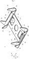
- Fig.1 shows a first embodiment of the earthing clamp 1.
- the earthing clamp has a rectangular plate 10 with a first and a second longitudinal edge 12, 14 in the longitudinal direction X, and a first and a second transverse edge 16, 18 in the transverse direction Y, perpendicular to the longitudinal direction X.
- the edges 12, 14, 16, 18 of the plate 10 are considered without the cable fastening areas 30, 32.
- the plate 10 can also have a square shape.
- the grounding clamp 1 is designed to accommodate one cable, preferably a coaxial cable, in each cable fastening area 30, 32.
- the first and second cable fastening areas 30, 32 extend along the first and second transverse edges 16, 18 of the plate 10.
- a crimping area 38a, b, c or d is arranged at each end of a cable fastening area 30, 32 in the transverse direction Y (see. Fig. 2 ).
- To attach a cable to the grounding clamp 1, the cable is aligned in the first or second cable attachment area 30, 32.
- a first or second cable guide 34, 36 simplifies the arrangement of the cable.
- the crimping areas 38a, b, c, d have a U-shaped or V-shaped taper to the cable guide 34, 36 of the respective first or second cable fastening area 30, 32.
- the taper is formed in each crimping area 38a, b, c, d by at least two opposing crimping tabs 37.
- a length of the crimping tabs 37 is preferably adapted to the cable thickness. The thicker the at least one cable to be fastened, the longer the corresponding crimping tabs 37 are.
- the crimping tabs of both crimping areas 38a, b or 38c, d are bent towards the center of the cable and the cable is crimped to the crimping tabs.
- the crimping areas 38a, b, c, d preferably have a structured surface in order to achieve a better, in particular more durable, fastening during crimping.
- the crimping firmly connects the cable to the grounding clamp 1.
- the crimped crimping tabs 37 can also have direct contact with a ground line of the cable.
- the cable's ground wire was stripped in the crimp areas 38a, b and 38c, d for this direct contact.
- the direct contact leads to an electrical connection between the cable's ground wire and the grounding clamp 1.
- the grounding clamp 1 can be attached to a separate body or surface via a fastening means, such as a screw or a bolt, which is guided through the opening 20 on the plate 10.
- the fastening means like the grounding clamp 1, is preferably electrically conductive and in particular made of metal. The electrical conductivity of the components makes it possible to establish an electrical connection between the cables attached to the grounding clamp 1, in particular the ground lines of the cables, and the surface to which the grounding clamp 1 is attached.
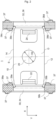
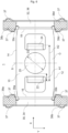
- Fig. 2 shows a plan view of the first embodiment of the earthing clamp 1.
- the earthing clamp 1 is symmetrical to a mirror axis S.
- the mirror axis S runs through the center of the opening 20 and is parallel to the two transverse edges 16, 18.
- the two cable fastening areas 30, 32 run parallel to each other at a distance that corresponds to the length of the first or second longitudinal edge 12, 14.
- the distance between the cable fastening areas 30, 32 is the maximum possible distance in relation to the plate 10.
- the opening 20 runs exactly in the middle of the plate 10, whereby a compact size of the earthing clamp 1 is achieved.
- the symmetrical design of the earthing clamp 1 also compensates for or prevents torques that may occur when tensile forces act on the cables and/or the distance between each cable and the opening 20 is different.
- Fig. 2 further shows an offset of opposite crimping tabs 37.
- This offset improves the result of the crimping and strengthens the attachment of the cables to the earthing clamp 1.
- a clearance 39a, b, c, d in the respective Crimping area 38a, b, c, d the result of crimping, as a flow of the material is allowed during the crimping process.
- the opening 20 has a diameter D2.
- the diameter D2 is adapted to the fastening means to be used and preferably accommodates the fastening means in a radially sealing manner.
- the diameter D2 of the first embodiment and the diameter D2 of a second embodiment can be different.
- the diameter D2 of the second embodiment is larger than the diameter D2 of the first embodiment. A larger diameter enables the insertion of a thicker fastening means, which is more stable with the same properties.
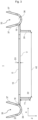
- Fig.3 shows a side view of the first embodiment of the earthing clamp 1, so that part of the underside U of the earthing clamp 1 is visible.
- the plate 10 has a thickness D1.
- the thickness D1 also corresponds to the thickness of the tabs 22 and 24.
- the tabs 22 and 24 are preferably formed by bending partial areas of the plate 10.
- the first and second tabs 22, 24 are identical. Both tabs protrude from the plate 10 with a depth T1, ie the length of the tabs 22, 24 in a direction Z on the underside U of the plate 10 corresponds to the depth T1.
- both tabs form a rectangular, flat shape with a first width B1 in the first embodiment and a second width B2 in a second embodiment.
- the first and second widths B1, B2 can be identical.
- the tabs 22, 24 preferably protrude perpendicularly from the plate 10. An inclination of the tabs 22, 24 of up to 10 degrees in both directions from the plate normal is possible in another embodiment.
- the first and second tabs 22, 24 are inserted into corresponding recesses in the separate surface.
- the recesses are essentially closed off by a tab, so that a tab cannot move or can only move insignificantly in the recess.
- the grounding clamp 1 thus sits securely on the separate surface in a way that prevents it from twisting.
- the grounding clamp is held securely in its position in a way that prevents it from twisting.
- the two tabs 22, 24 are bent directly at the respective transverse edge 16, 18 in the direction of the underside U of the plate 10.
- the distance between the first cable fastening area 30 and the first tab 22 in a first direction or longitudinal direction X is as small as possible.
- any horizontal tensile forces that may occur on the clamp are distributed over at least three points, ie the fastening means in the opening 20 and the two tabs 22, 24 in the corresponding recesses, which leads to a reduction in the load on the earthing clamp 1 and a longer service life.
- the first and second cable fastening area 30, 32 in Fig.3 has a U-shaped or V-shaped cross-section.
- the legs of the U- or V-shape are formed by at least two adjacent crimping tabs 37 in a crimping area 38a, b, c, d.
- a connecting piece between adjacent crimping tabs 37 at the level of the plate 10 forms a cable guide 34, 36 in the form of a groove.
- the groove facilitates the cable arrangement.
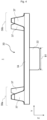
- the cable guide 34, 36 in the form of a groove connects the two crimping areas 38a, b and 38c, d to one another in each cable fastening area 30, 32 (see Fig.4 ).
- Fig.5 shows a second embodiment of the earthing clamp 1.
- the second embodiment differs from the first embodiment at least in that the first and second tabs 22, 24 are not formed directly on the first and second transverse edges 16, 18, respectively, but in the middle of the plate 10.
- the two tabs 22, 24 extend at a small first distance A1 parallel to an imaginary tangent on opposite sides of the opening 20, in a direction Z to the underside U of the plate 10.
- the two tabs 22, 24 are preferably formed by bending corresponding sections of the plate 10.
- the first distance A1 between a tab 22, 24 and the corresponding imaginary tangent of the opening 20 is selected such that a second distance A2 between the first and second tabs 22, 24 essentially corresponds to the edge diameter of a bolt nut onto which the grounding clamp 1 is arranged and fastened during assembly.
- the bolt nut is preferably an octagonal nut, in which the distance between two opposite edges essentially corresponds to the second distance A2 between the first and second tabs 22, 24.
- the length of the first and second longitudinal edges 12, 14 is preferably in the range of 15 - 25 mm, more preferably in the range of 19 - 21 mm.
- the length of the first and second transverse edges 16, 18 is preferably in the range of 10 - 15 mm, more preferably in the range of 12 - 14 mm.
- the second distance A2 between the first and second tabs 22, 24 is in the range of 16 - 22 mm, more preferably in the range of 18 - 20 mm. In the second embodiment, the second distance A2 between the first and second tabs 22, 24 is preferably in the range of 8 - 16 mm, more preferably in the range of 11 - 13 mm.
- the grounding clamp 1 of the first and second embodiments is preferably made of an electrically conductive material, in particular of metal.
- the grounding clamp 1 in both embodiments was made from one piece.
Landscapes
- Clamps And Clips (AREA)
- Engineering & Computer Science (AREA)
- Architecture (AREA)
- Civil Engineering (AREA)
- Structural Engineering (AREA)
- Connections Effected By Soldering, Adhesion, Or Permanent Deformation (AREA)
Claims (8)
- Collier de serrage de mise à la terre (1) servant à la fixation et à la mise en contact électrique d'au moins deux câbles sur une surface séparée, présentant :une plaque (10) dotée d'un premier bord longitudinal (12) et d'un deuxième bord longitudinal (14) opposé au premier bord longitudinal (12), les deux bords longitudinaux (12, 14) s'étendant dans une première direction (X) de la plaque (10), et d'un premier bord transversal (16) et d'un deuxième bord transversal (18) opposé au premier bord transversal (16), les deux bords transversaux (16, 18) s'étendant perpendiculairement au premier et au deuxième bord longitudinal (12, 14) dans une deuxième direction (Y) de la plaque (10) ;une première région de fixation de câble (30) servant à la fixation et à la mise en contact électrique d'un premier câble sur la plaque (10), la première région de fixation de câble (30) s'étendant le long du premier bord transversal (16) ;une deuxième région de fixation de câble (32) servant à la fixation et à la mise en contact électrique d'un deuxième câble séparé sur la plaque (10), la deuxième région de fixation de câble (32) s'étendant le long du deuxième bord transversal (18) ;une ouverture (20), disposée entre la première et la deuxième région de fixation de câble (30, 32), servant à l'insertion d'un moyen de fixation ;une première languette (22), qui s'étend entre la première et la deuxième région de fixation de câble (30, 32) parallèlement au premier bord transversal (16) et perpendiculairement au plan de plaque dans la direction (Z) d'un côté inférieur (U) de la plaque (10) ; etune deuxième languette (24), qui s'étend entre la première et la deuxième région de fixation de câble (30, 32) parallèlement au deuxième bord transversal (18) et perpendiculairement au plan de plaque dans la direction (Z) du côté inférieur (U) de la plaque (10).
- Collier de serrage de mise à la terre (1) selon la revendication 1, dans lequel la première languette (22) s'étend le long du premier bord transversal (16) et la deuxième languette (24) s'étend le long du deuxième bord transversal (18).
- Collier de serrage de mise à la terre (1) selon la revendication 1, dans lequel la première languette (22) s'étend à une première distance (A1) de l'ouverture (20), entre l'ouverture (20) et le premier bord transversal (16), et la deuxième languette (24) s'étend à la première distance (A1) de l'ouverture (20), entre l'ouverture (20) et le deuxième bord transversal (18), de sorte que le collier de serrage de mise à la terre (1) peut être disposé à l'aide de la première et de la deuxième languette (22, 24) de manière bloquée en rotation sur une partie d'un moyen de fixation qui peut être disposé dans l'ouverture (20).
- Collier de serrage de mise à la terre (1) selon l'une des revendications 1 à 3, dans lequel l'ouverture (20) est circulaire.
- Collier de serrage de mise à la terre (1) selon l'une des revendications 1 à 4, le collier de serrage de mise à la terre (1) présentant un matériau électro-conducteur, de sorte qu'une connexion électrique existe entre au moins un câble électrique pouvant être fixé et le moyen de fixation pouvant être inséré dans l'ouverture (20) .
- Collier de serrage de mise à la terre (1) selon l'une des revendications 1 à 5, le collier de serrage de mise à la terre (1) étant construit en symétrie miroir par rapport à un axe miroir (S), et l'axe miroir (S) s'étendant parallèlement au premier et au deuxième bord transversal (16, 18) à travers le centre de l'ouverture (20) .
- Collier de serrage de mise à la terre (1) selon l'une des revendications 1 à 6, la première et la deuxième région de fixation de câble (30, 32) présentant respectivement un guide de câble (34, 36) et au moins une première et une deuxième région de sertissage (38a, b, c, d), à des extrémités opposées du guide de câble (34, 36) respectif.
- Collier de serrage de mise à la terre (1) selon l'une des revendications 1 à 7, dans lequel la plaque (10) est une plaque allongée (10), et la première direction (X) est la direction longitudinale de la plaque (10) .
Applications Claiming Priority (1)
| Application Number | Priority Date | Filing Date | Title |
|---|---|---|---|
| DE202020106373.1U DE202020106373U1 (de) | 2020-11-06 | 2020-11-06 | Erdungsschelle mit Verdrehschutz |
Publications (3)
| Publication Number | Publication Date |
|---|---|
| EP3996207A1 EP3996207A1 (fr) | 2022-05-11 |
| EP3996207B1 true EP3996207B1 (fr) | 2024-06-26 |
| EP3996207C0 EP3996207C0 (fr) | 2024-06-26 |
Family
ID=73747310
Family Applications (1)
| Application Number | Title | Priority Date | Filing Date |
|---|---|---|---|
| EP21205022.3A Active EP3996207B1 (fr) | 2020-11-06 | 2021-10-27 | Collier de serrage de mise à la terre à protection contre la rotation |
Country Status (4)
| Country | Link |
|---|---|
| US (1) | US11728582B2 (fr) |
| EP (1) | EP3996207B1 (fr) |
| CN (1) | CN114447641B (fr) |
| DE (1) | DE202020106373U1 (fr) |
Families Citing this family (1)
| Publication number | Priority date | Publication date | Assignee | Title |
|---|---|---|---|---|
| FR3136322B1 (fr) * | 2022-06-02 | 2024-11-29 | Renault Sas | Borne de mise à la masse multiple modulaire |
Family Cites Families (11)
| Publication number | Priority date | Publication date | Assignee | Title |
|---|---|---|---|---|
| DE102005003193A1 (de) * | 2005-01-24 | 2006-08-10 | Robert Bosch Gmbh | Vorrichtung zum Klemmen mindestens eines elektrischen Leiters |
| JP4235185B2 (ja) | 2005-02-24 | 2009-03-11 | 矢崎総業株式会社 | アースプレート及びこれに同軸線を取り付けるための治具 |
| DE102007005964A1 (de) * | 2006-03-24 | 2008-10-30 | Icotek Project Gmbh & Co. Kg | Befestigungsvorrichtung |
| JP5699942B2 (ja) | 2012-01-12 | 2015-04-15 | 株式会社オートネットワーク技術研究所 | 端子付き電線 |
| DE102014200271A1 (de) * | 2014-01-10 | 2015-07-16 | MCQ TECH GmbH | Leiterplattenanschlussklemme |
| JP2016219221A (ja) * | 2015-05-19 | 2016-12-22 | ホシデン株式会社 | シールドケース及びこれを備えたコネクタ |
| DE102015115791B4 (de) * | 2015-09-18 | 2017-05-04 | Wago Verwaltungsgesellschaft Mbh | Leiteranschlusskontaktelement |
| JP6265963B2 (ja) | 2015-11-30 | 2018-01-24 | 矢崎総業株式会社 | 端子金具の接続方法 |
| JP6302452B2 (ja) | 2015-11-30 | 2018-03-28 | 矢崎総業株式会社 | 端子金具の接続構造 |
| DE102016222708B4 (de) * | 2016-11-18 | 2024-06-06 | Bayerische Motoren Werke Aktiengesellschaft | Aufnahmevorrichtung zur Aufnahme eines leitungsförmigen Bauteils |
| FR3074369B3 (fr) * | 2017-11-24 | 2019-12-20 | A Raymond Et Cie | Clip de mise a la terre muni de pointes de mise en contact electrique et assemblage de mise a la terre |
-
2020
- 2020-11-06 DE DE202020106373.1U patent/DE202020106373U1/de active Active
-
2021
- 2021-10-15 US US17/502,058 patent/US11728582B2/en active Active
- 2021-10-27 EP EP21205022.3A patent/EP3996207B1/fr active Active
- 2021-10-29 CN CN202111277339.2A patent/CN114447641B/zh active Active
Also Published As
| Publication number | Publication date |
|---|---|
| CN114447641B (zh) | 2025-09-09 |
| US11728582B2 (en) | 2023-08-15 |
| US20220149604A1 (en) | 2022-05-12 |
| EP3996207C0 (fr) | 2024-06-26 |
| DE202020106373U1 (de) | 2020-11-19 |
| CN114447641A (zh) | 2022-05-06 |
| EP3996207A1 (fr) | 2022-05-11 |
Similar Documents
| Publication | Publication Date | Title |
|---|---|---|
| DE102019128908B4 (de) | Leiteranschlussklemme | |
| EP2012400A2 (fr) | Boîte de connexion de câble | |
| DE102015110788B4 (de) | Anschlussverbindungsstruktur | |
| EP2091113B1 (fr) | Système de raccordement pour bandes lumineuses ou lampes | |
| EP3996207B1 (fr) | Collier de serrage de mise à la terre à protection contre la rotation | |
| DE60127600T2 (de) | Abzweigverbinder | |
| EP1744404B2 (fr) | Dispositif de connexion et système de connexion pour conducteurs électriques isolés | |
| DE102023110642A1 (de) | Steckverbindungssystem und elektrifiziertes kraftfahrzeug mit einem solchen steckverbindungssystem | |
| EP4002595B1 (fr) | Collier de mise à la terre pourvu de protection latérale contre la rotation | |
| EP0681343B1 (fr) | Système pour le raccordement à la masse de câbles électriques, en particulier à une carrosserie automobile | |
| DE102009016087A1 (de) | Sammelschienen-Anschlussklemmen-Konstruktion | |
| DE102018003391B4 (de) | Anschlussfeld, Anordnung mit demselben und elektrischer Antriebsstrang | |
| EP4038693B1 (fr) | Unité de raccordement dotée d'éléments d'actionnement et d'ouvertures de raccordement de conducteur agencés en deux rangées | |
| EP4097798B1 (fr) | Contact de mise à la terre de protection et borne de connexion de conducteur | |
| EP3183779B1 (fr) | Élément de contact et connecteur | |
| EP1587166B1 (fr) | Bloc de répartition | |
| WO2000062386A1 (fr) | Groupe d'appareils de commutation comportant un systeme de barres de distribution pourvu d'un encapsulage d'isolation | |
| EP4175074B1 (fr) | Borne de mise à la terre et ensemble de connexion | |
| EP4109684B1 (fr) | Agencement de contact | |
| EP4115475B1 (fr) | Appareil de connexion, et ensemble et dispositif électronique | |
| DE102024115467B4 (de) | Leiterseilklemme und Potentialausgleichsanordnung mit Leiterseilklemme | |
| EP3876362B1 (fr) | Pince de fixation | |
| DE102017011561A1 (de) | Stabilisierungselement für eine Streifensicherung | |
| EP4572025A1 (fr) | Connecteur électrique et système de connecteur électrique | |
| DE102018111050A1 (de) | Anschlusshalter, System mit solch einem Anschlusshalter und Verfahren zur Montage solch eines Systems |
Legal Events
| Date | Code | Title | Description |
|---|---|---|---|
| PUAI | Public reference made under article 153(3) epc to a published international application that has entered the european phase |
Free format text: ORIGINAL CODE: 0009012 |
|
| STAA | Information on the status of an ep patent application or granted ep patent |
Free format text: STATUS: THE APPLICATION HAS BEEN PUBLISHED |
|
| AK | Designated contracting states |
Kind code of ref document: A1 Designated state(s): AL AT BE BG CH CY CZ DE DK EE ES FI FR GB GR HR HU IE IS IT LI LT LU LV MC MK MT NL NO PL PT RO RS SE SI SK SM TR |
|
| STAA | Information on the status of an ep patent application or granted ep patent |
Free format text: STATUS: REQUEST FOR EXAMINATION WAS MADE |
|
| 17P | Request for examination filed |
Effective date: 20221111 |
|
| RBV | Designated contracting states (corrected) |
Designated state(s): AL AT BE BG CH CY CZ DE DK EE ES FI FR GB GR HR HU IE IS IT LI LT LU LV MC MK MT NL NO PL PT RO RS SE SI SK SM TR |
|
| GRAP | Despatch of communication of intention to grant a patent |
Free format text: ORIGINAL CODE: EPIDOSNIGR1 |
|
| STAA | Information on the status of an ep patent application or granted ep patent |
Free format text: STATUS: GRANT OF PATENT IS INTENDED |
|
| RIC1 | Information provided on ipc code assigned before grant |
Ipc: H01R 11/05 20060101ALN20240220BHEP Ipc: H01R 9/05 20060101ALN20240220BHEP Ipc: H01R 4/34 20060101ALN20240220BHEP Ipc: H01R 11/09 20060101ALI20240220BHEP Ipc: H01R 4/18 20060101AFI20240220BHEP |
|
| INTG | Intention to grant announced |
Effective date: 20240315 |
|
| GRAS | Grant fee paid |
Free format text: ORIGINAL CODE: EPIDOSNIGR3 |
|
| GRAA | (expected) grant |
Free format text: ORIGINAL CODE: 0009210 |
|
| STAA | Information on the status of an ep patent application or granted ep patent |
Free format text: STATUS: THE PATENT HAS BEEN GRANTED |
|
| AK | Designated contracting states |
Kind code of ref document: B1 Designated state(s): AL AT BE BG CH CY CZ DE DK EE ES FI FR GB GR HR HU IE IS IT LI LT LU LV MC MK MT NL NO PL PT RO RS SE SI SK SM TR |
|
| REG | Reference to a national code |
Ref country code: GB Ref legal event code: FG4D Free format text: NOT ENGLISH |
|
| REG | Reference to a national code |
Ref country code: CH Ref legal event code: EP |
|
| REG | Reference to a national code |
Ref country code: DE Ref legal event code: R096 Ref document number: 502021004102 Country of ref document: DE |
|
| U01 | Request for unitary effect filed |
Effective date: 20240626 |
|
| U07 | Unitary effect registered |
Designated state(s): AT BE BG DE DK EE FI FR IT LT LU LV MT NL PT SE SI Effective date: 20240704 |
|
| PG25 | Lapsed in a contracting state [announced via postgrant information from national office to epo] |
Ref country code: HR Free format text: LAPSE BECAUSE OF FAILURE TO SUBMIT A TRANSLATION OF THE DESCRIPTION OR TO PAY THE FEE WITHIN THE PRESCRIBED TIME-LIMIT Effective date: 20240626 |
|
| PG25 | Lapsed in a contracting state [announced via postgrant information from national office to epo] |
Ref country code: GR Free format text: LAPSE BECAUSE OF FAILURE TO SUBMIT A TRANSLATION OF THE DESCRIPTION OR TO PAY THE FEE WITHIN THE PRESCRIBED TIME-LIMIT Effective date: 20240927 |
|
| PG25 | Lapsed in a contracting state [announced via postgrant information from national office to epo] |
Ref country code: NO Free format text: LAPSE BECAUSE OF FAILURE TO SUBMIT A TRANSLATION OF THE DESCRIPTION OR TO PAY THE FEE WITHIN THE PRESCRIBED TIME-LIMIT Effective date: 20240926 Ref country code: HR Free format text: LAPSE BECAUSE OF FAILURE TO SUBMIT A TRANSLATION OF THE DESCRIPTION OR TO PAY THE FEE WITHIN THE PRESCRIBED TIME-LIMIT Effective date: 20240626 Ref country code: GR Free format text: LAPSE BECAUSE OF FAILURE TO SUBMIT A TRANSLATION OF THE DESCRIPTION OR TO PAY THE FEE WITHIN THE PRESCRIBED TIME-LIMIT Effective date: 20240927 Ref country code: RS Free format text: LAPSE BECAUSE OF FAILURE TO SUBMIT A TRANSLATION OF THE DESCRIPTION OR TO PAY THE FEE WITHIN THE PRESCRIBED TIME-LIMIT Effective date: 20240926 |
|
| U20 | Renewal fee for the european patent with unitary effect paid |
Year of fee payment: 4 Effective date: 20241031 |
|
| PG25 | Lapsed in a contracting state [announced via postgrant information from national office to epo] |
Ref country code: PL Free format text: LAPSE BECAUSE OF FAILURE TO SUBMIT A TRANSLATION OF THE DESCRIPTION OR TO PAY THE FEE WITHIN THE PRESCRIBED TIME-LIMIT Effective date: 20240626 |
|
| PG25 | Lapsed in a contracting state [announced via postgrant information from national office to epo] |
Ref country code: IS Free format text: LAPSE BECAUSE OF FAILURE TO SUBMIT A TRANSLATION OF THE DESCRIPTION OR TO PAY THE FEE WITHIN THE PRESCRIBED TIME-LIMIT Effective date: 20241026 |
|
| PG25 | Lapsed in a contracting state [announced via postgrant information from national office to epo] |
Ref country code: CZ Free format text: LAPSE BECAUSE OF FAILURE TO SUBMIT A TRANSLATION OF THE DESCRIPTION OR TO PAY THE FEE WITHIN THE PRESCRIBED TIME-LIMIT Effective date: 20240626 |
|
| PG25 | Lapsed in a contracting state [announced via postgrant information from national office to epo] |
Ref country code: RO Free format text: LAPSE BECAUSE OF FAILURE TO SUBMIT A TRANSLATION OF THE DESCRIPTION OR TO PAY THE FEE WITHIN THE PRESCRIBED TIME-LIMIT Effective date: 20240626 Ref country code: SK Free format text: LAPSE BECAUSE OF FAILURE TO SUBMIT A TRANSLATION OF THE DESCRIPTION OR TO PAY THE FEE WITHIN THE PRESCRIBED TIME-LIMIT Effective date: 20240626 |
|
| PG25 | Lapsed in a contracting state [announced via postgrant information from national office to epo] |
Ref country code: ES Free format text: LAPSE BECAUSE OF FAILURE TO SUBMIT A TRANSLATION OF THE DESCRIPTION OR TO PAY THE FEE WITHIN THE PRESCRIBED TIME-LIMIT Effective date: 20240626 Ref country code: SM Free format text: LAPSE BECAUSE OF FAILURE TO SUBMIT A TRANSLATION OF THE DESCRIPTION OR TO PAY THE FEE WITHIN THE PRESCRIBED TIME-LIMIT Effective date: 20240626 |
|
| PG25 | Lapsed in a contracting state [announced via postgrant information from national office to epo] |
Ref country code: SM Free format text: LAPSE BECAUSE OF FAILURE TO SUBMIT A TRANSLATION OF THE DESCRIPTION OR TO PAY THE FEE WITHIN THE PRESCRIBED TIME-LIMIT Effective date: 20240626 Ref country code: SK Free format text: LAPSE BECAUSE OF FAILURE TO SUBMIT A TRANSLATION OF THE DESCRIPTION OR TO PAY THE FEE WITHIN THE PRESCRIBED TIME-LIMIT Effective date: 20240626 Ref country code: RO Free format text: LAPSE BECAUSE OF FAILURE TO SUBMIT A TRANSLATION OF THE DESCRIPTION OR TO PAY THE FEE WITHIN THE PRESCRIBED TIME-LIMIT Effective date: 20240626 Ref country code: PL Free format text: LAPSE BECAUSE OF FAILURE TO SUBMIT A TRANSLATION OF THE DESCRIPTION OR TO PAY THE FEE WITHIN THE PRESCRIBED TIME-LIMIT Effective date: 20240626 Ref country code: IS Free format text: LAPSE BECAUSE OF FAILURE TO SUBMIT A TRANSLATION OF THE DESCRIPTION OR TO PAY THE FEE WITHIN THE PRESCRIBED TIME-LIMIT Effective date: 20241026 Ref country code: ES Free format text: LAPSE BECAUSE OF FAILURE TO SUBMIT A TRANSLATION OF THE DESCRIPTION OR TO PAY THE FEE WITHIN THE PRESCRIBED TIME-LIMIT Effective date: 20240626 Ref country code: CZ Free format text: LAPSE BECAUSE OF FAILURE TO SUBMIT A TRANSLATION OF THE DESCRIPTION OR TO PAY THE FEE WITHIN THE PRESCRIBED TIME-LIMIT Effective date: 20240626 |
|
| PLBE | No opposition filed within time limit |
Free format text: ORIGINAL CODE: 0009261 |
|
| STAA | Information on the status of an ep patent application or granted ep patent |
Free format text: STATUS: NO OPPOSITION FILED WITHIN TIME LIMIT |
|
| REG | Reference to a national code |
Ref country code: CH Ref legal event code: PL |
|
| 26N | No opposition filed |
Effective date: 20250327 |
|
| PG25 | Lapsed in a contracting state [announced via postgrant information from national office to epo] |
Ref country code: MC Free format text: LAPSE BECAUSE OF FAILURE TO SUBMIT A TRANSLATION OF THE DESCRIPTION OR TO PAY THE FEE WITHIN THE PRESCRIBED TIME-LIMIT Effective date: 20240626 |
|
| PG25 | Lapsed in a contracting state [announced via postgrant information from national office to epo] |
Ref country code: CH Free format text: LAPSE BECAUSE OF NON-PAYMENT OF DUE FEES Effective date: 20241031 |
|
| PG25 | Lapsed in a contracting state [announced via postgrant information from national office to epo] |
Ref country code: IE Free format text: LAPSE BECAUSE OF NON-PAYMENT OF DUE FEES Effective date: 20241027 |
|
| U20 | Renewal fee for the european patent with unitary effect paid |
Year of fee payment: 5 Effective date: 20251031 |
|
| PG25 | Lapsed in a contracting state [announced via postgrant information from national office to epo] |
Ref country code: CY Free format text: LAPSE BECAUSE OF FAILURE TO SUBMIT A TRANSLATION OF THE DESCRIPTION OR TO PAY THE FEE WITHIN THE PRESCRIBED TIME-LIMIT; INVALID AB INITIO Effective date: 20211027 |
|
| PG25 | Lapsed in a contracting state [announced via postgrant information from national office to epo] |
Ref country code: HU Free format text: LAPSE BECAUSE OF FAILURE TO SUBMIT A TRANSLATION OF THE DESCRIPTION OR TO PAY THE FEE WITHIN THE PRESCRIBED TIME-LIMIT; INVALID AB INITIO Effective date: 20211027 |