EP3997018B1 - Fördervorrichtung mit einem elektromotor - Google Patents
Fördervorrichtung mit einem elektromotor Download PDFInfo
- Publication number
- EP3997018B1 EP3997018B1 EP20736575.0A EP20736575A EP3997018B1 EP 3997018 B1 EP3997018 B1 EP 3997018B1 EP 20736575 A EP20736575 A EP 20736575A EP 3997018 B1 EP3997018 B1 EP 3997018B1
- Authority
- EP
- European Patent Office
- Prior art keywords
- flange
- hollow shaft
- conveyor according
- stator housing
- electric motor
- Prior art date
- Legal status (The legal status is an assumption and is not a legal conclusion. Google has not performed a legal analysis and makes no representation as to the accuracy of the status listed.)
- Active
Links
Images


Classifications
-
- H—ELECTRICITY
- H02—GENERATION; CONVERSION OR DISTRIBUTION OF ELECTRIC POWER
- H02K—DYNAMO-ELECTRIC MACHINES
- H02K7/00—Arrangements for handling mechanical energy structurally associated with dynamo-electric machines, e.g. structural association with mechanical driving motors or auxiliary dynamo-electric machines
- H02K7/003—Couplings; Details of shafts
-
- B—PERFORMING OPERATIONS; TRANSPORTING
- B65—CONVEYING; PACKING; STORING; HANDLING THIN OR FILAMENTARY MATERIAL
- B65G—TRANSPORT OR STORAGE DEVICES, e.g. CONVEYORS FOR LOADING OR TIPPING, SHOP CONVEYOR SYSTEMS OR PNEUMATIC TUBE CONVEYORS
- B65G23/00—Driving gear for endless conveyors; Belt- or chain-tensioning arrangements
- B65G23/22—Arrangements or mountings of driving motors
-
- H—ELECTRICITY
- H02—GENERATION; CONVERSION OR DISTRIBUTION OF ELECTRIC POWER
- H02K—DYNAMO-ELECTRIC MACHINES
- H02K1/00—Details of the magnetic circuit
- H02K1/06—Details of the magnetic circuit characterised by the shape, form or construction
- H02K1/12—Stationary parts of the magnetic circuit
-
- H—ELECTRICITY
- H02—GENERATION; CONVERSION OR DISTRIBUTION OF ELECTRIC POWER
- H02K—DYNAMO-ELECTRIC MACHINES
- H02K1/00—Details of the magnetic circuit
- H02K1/06—Details of the magnetic circuit characterised by the shape, form or construction
- H02K1/22—Rotating parts of the magnetic circuit
-
- H—ELECTRICITY
- H02—GENERATION; CONVERSION OR DISTRIBUTION OF ELECTRIC POWER
- H02K—DYNAMO-ELECTRIC MACHINES
- H02K5/00—Casings; Enclosures; Supports
- H02K5/04—Casings or enclosures characterised by the shape, form or construction thereof
-
- H—ELECTRICITY
- H02—GENERATION; CONVERSION OR DISTRIBUTION OF ELECTRIC POWER
- H02K—DYNAMO-ELECTRIC MACHINES
- H02K5/00—Casings; Enclosures; Supports
- H02K5/04—Casings or enclosures characterised by the shape, form or construction thereof
- H02K5/16—Means for supporting bearings, e.g. insulating supports or means for fitting bearings in the bearing-shields
- H02K5/161—Means for supporting bearings, e.g. insulating supports or means for fitting bearings in the bearing-shields radially supporting the rotary shaft at both ends of the rotor
-
- H—ELECTRICITY
- H02—GENERATION; CONVERSION OR DISTRIBUTION OF ELECTRIC POWER
- H02K—DYNAMO-ELECTRIC MACHINES
- H02K7/00—Arrangements for handling mechanical energy structurally associated with dynamo-electric machines, e.g. structural association with mechanical driving motors or auxiliary dynamo-electric machines
- H02K7/10—Structural association with clutches, brakes, gears, pulleys or mechanical starters
- H02K7/116—Structural association with clutches, brakes, gears, pulleys or mechanical starters with gears
-
- H—ELECTRICITY
- H02—GENERATION; CONVERSION OR DISTRIBUTION OF ELECTRIC POWER
- H02K—DYNAMO-ELECTRIC MACHINES
- H02K9/00—Arrangements for cooling or ventilating
- H02K9/22—Arrangements for cooling or ventilating by solid heat conducting material embedded in, or arranged in contact with, the stator or rotor, e.g. heat bridges
- H02K9/227—Heat sinks
Definitions
- the invention relates to a conveying device with an electric motor.
- a manufacturing method for a conveying device having a gear wheel connected to a shaft in a rotationally fixed manner, the teeth of which are in engagement with the teeth of another gear wheel for conveying conveying medium between a first channel region and a second channel region.
- a belt conveyor system is known from EP 2 562 102 A1.
- the invention is therefore based on the object of developing a conveying device that can be operated cost-effectively.
- the object is achieved in the conveying device according to the features specified in claim 1.
- the electric motor can be attached directly to the supporting part and is held by it.
- the hollow shaft can be connected directly to the solid shaft of the conveyor device that is to be driven, i.e. without an intermediate gear.
- a gear can be dispensed with and thus the conveyor device can be operated cost-effectively, in particular with lower energy losses.
- the electric motor In order to generate a sufficiently high torque, however, the electric motor must be designed as a synchronous motor.
- the starting torque of a conveyor device is high because the solid shaft drives a belt via a roller or a conveyor chain via a gear wheel and both the belt and the chain are tensioned. This results in high friction forces, so a high starting torque must be generated by the motor.
- the spring parts enable the flange to be connected to the second support part after the solid shaft has been connected to the hollow shaft, thus enabling the flange to be aligned with the
- the flange can also be shifted, although the spring parts generate an increasing counterforce with increasing displacement. In this way, the flange can be shifted, but a restoring force is also created if the displacement is too great.
- the spring parts ensure that a certain residual tension remains in the system when the axis of rotation of the solid shaft and/or hollow shaft deviates from its ideal position due to manufacturing tolerances, which prevents loose play.
- the bearings are also subjected to this residual tension and the parts of the system are elastically deflected. Overall, this is a small residual tension that can be absorbed by the system.
- the flange is therefore preferably made of a softer material than the second supporting part. In this way, the flange itself also absorbs part of the remaining stress.
- a second bearing for the rotatable mounting of the solid shaft is arranged in the first support part.
- the solid shaft can be mounted on both sides. On the one hand, it is mounted in the second bearing and on the other hand, via the hollow shaft, in the bearings of the motor.
- the spring part is made of an elastic material, in particular of an elastomer and/or rubber, and/or is ring-shaped, in particular, the spring part has a radially protruding collar which runs around the ring axis of the ring-shaped spring part in the circumferential direction, in particular which limits the spring part in the axial direction on the flange.
- the flange is made of a material, in one piece and/or in one part, whose modulus of elasticity is greater than the modulus of elasticity of the second supporting part.
- the hollow shaft has a centrally arranged recess in the form of a blind hole or has a bore that runs axially through the hollow shaft.
- the area covered by the hollow shaft in the axial direction comprises the area covered by the stator housing, in particular, so that the hollow shaft protrudes from the stator housing on both sides in and against the axial direction.
- the advantage here is that the hollow shaft protrudes on both sides and thus the solid shaft has a sufficiently long axial connection area available.
- the second supporting part is made of steel and the flange is made of aluminum.
- the advantage here is that the residual stress in the flange can be at least partially absorbed.
- the recesses that run axially through the flange part to accommodate the spring parts form a square hole pattern, especially when viewed in the axial direction.
- the advantage here is that the corner areas of the flange can be used.
- the flange is shaped as a truncated pyramid with a square base, in particular, a respective spring part is arranged in a respective corner area of the square.
- the vertical projection of the spring parts onto a plane whose normal direction is aligned parallel to the axis of rotation of the hollow shaft of the electric motor is spaced apart from the vertical projection of the stator housing onto this plane.
- a converter is connected to the stator housing,
- the vertical projection of the spring parts onto a plane whose normal direction is aligned parallel to the axis of rotation of the hollow shaft of the electric motor is spaced apart from the vertical projection of the converter onto this plane.
- cooling fins are formed on the flange.
- the cooling fins extend axially and are evenly spaced from one another in the circumferential direction relative to the axis of rotation of the solid shaft, although no cooling fins are arranged in the circumferential angle range covered by the respective spring part, in particular by its collar, but rather in the area covered by the cooling fins in the axial direction, the radial distance range covered by the flange is smaller than and/or spaced from the radial distance range covered by the spring parts. This keeps a space area free of cooling fins, which can be used to operate the screw parts.
- the conveying device has a solid shaft 4 which is rotatably mounted in a first supporting part 1 via a bearing, in particular a rolling bearing.
- a second bearing for the rotatable mounting of the solid shaft 4 is also arranged, wherein the solid shaft 4 protrudes on both sides of this second bearing.
- the electric motor is arranged on the side of the second support part 2 facing away from the first support part 1.
- a flange 5 of the electric motor is screwed to the second supporting part 2.
- a stator housing 7 of the electric motor is screwed to the flange 5.
- a rotor 20 is arranged on a hollow shaft 21 and connected thereto in a rotationally fixed manner.
- the hollow shaft 21 is rotatably supported by two bearings of the electric motor which are accommodated in the stator housing 7, in particular in two bearing flanges connected to the stator housing 7.
- the hollow shaft 21 is connected to the solid shaft 4 in a rotationally fixed manner, in particular in a force-fitting manner by means of a shrink screw.
- screw parts such as connecting screws or threaded bolts with screw nuts are used.
- the flange 5 has axially continuous recesses through which the screw parts protrude.
- a respective spring part 30, which is formed in a ring shape, is arranged in the respective recess.
- the respective screw part is passed through a respective spring part 30.
- the screw parts therefore do not touch the flange 5 directly.
- a respective spring part 30 is therefore arranged between each screw part.
- the spring parts 30 are designed as rubber grommets.
- the spring parts 30 center the electric motor. This is because the coaxial alignment of the solid shaft 4 to the hollow shaft 21 is important. First, the solid shaft 4 is connected to the hollow shaft 21 and only then are the screw parts screwed tight with nuts. Therefore, the spring parts 30 are already deformed before this screwing in order to compensate for tolerances.
- the spring parts 30 each have a circumferential collar in one of their axial end regions, so that they can only be inserted into the axial bore holes until the respective collar rests. The respective collar thus limits the respective axial insertion.
- a converter 6 is connected to the stator housing 7 so that the electric motor can be operated by the converter in a speed-controlled or torque-controlled manner.
- a roller 3 is connected in a rotationally fixed manner to the solid shaft 4.
- the roller 3 preferably drives a belt or a strap.
- the radial distance area covered by the flange 5 comprises the radial distance area covered by the roller 3. Preferably, it is radially extended further such that the screw parts can be connected radially outside the roller 3.
- the axial direction is aligned parallel to the axis of rotation of the solid shaft 4.
- the hollow shaft 21 is designed with a blind hole-like cavity. This means that the cavity of the hollow shaft 21 is not continuous, but rather blind hole-like.
- the hollow shaft 21 therefore has a solid shaft area at its end area facing away from the flange 5, which closes off the adjacent hollow shaft area. This means that an increased degree of protection can be achieved. No liquid can enter the interior of the motor from the cavity. In addition, an axial limitation is achieved for the solid shaft 4 inserted into the hollow shaft area.
- the lateral extension of the flange 5 is also greater than the extension of the converter 6 in this direction.
- the screw parts can be passed through the continuous recesses of the spring parts 30 and thus also through the axial bores of the flange 5 that accommodate the spring parts 30.
- the screw parts 30 can therefore be actuated by the converter 6 without interference or hindrance. It is therefore advantageous that the vertical projection of the spring parts 30 onto a plane whose normal direction is aligned parallel to the axis of rotation of the hollow shaft 21 of the electric motor is spaced from the vertical projection of the converter onto this plane, in particular and even from the vertical projection of the stator housing onto this plane.
- the flange 5 is made of a material that is softer, i.e. has a higher modulus of elasticity, than the material of the second support part 2, and harder, i.e. has a lower modulus of elasticity, than the spring parts 30.
- the material preferably has a higher thermal conductivity than steel. The heat flowing from the stator housing 7 into the flange 5 can thus be spread out in the flange 5 and passed on to the second support part 2, which can thus also be made of steel. This is because the spread out heat flow can be absorbed sufficiently well even by a poorer heat conductor and passed on to the environment.
- the flange 5 has cooling fins on its outer side which run in the axial direction.
- the hollow shaft 21 is axially guided through the center of the flange and thus protrudes axially on both sides.
- the flange 5 is pyramid-shaped with a square base.
- the outer circumference of the vertical projection of the flange 5 into a plane whose normal is aligned parallel to the axial direction, i.e. parallel to the axis of rotation of the hollow shaft 21, is a square.
- an axially continuous cavity is used instead of the blind hole-like cavity.
- the hollow shaft 21 then has an axially continuous cylindrical cavity, in particular the hollow shaft is then designed as a hollow cylinder. This enables a cost-effective design in which the insertion depth of the solid shaft 4 is not fixed.
- the axial end of the hollow shaft 21 is not arranged in the axial region covered by the rotor 20, but the axial region covered by the hollow shaft 21 even includes the entire axial region covered by the rotor 20.
- the hollow shaft protrudes from the electric motor, in particular from its stator housing 7, on the B side and on the A side.
- Heat from the stator housing can also be dissipated via the flange to the second supporting part 2. This allows for improved heat dissipation of the motor.
- the bearing accommodated in the second support part 2 i.e. the second bearing
- the bearings of the hollow shaft 21 arranged in the electric motor also take over the bearing of the solid shaft 4 after the solid shaft 4 is connected to the hollow shaft 21.
- the solid shaft 4 is then only supported via the first bearing, which is accommodated in the first support part 1, and via the bearings in the stator housing 7. This reduces losses and in particular the heat input into the second supporting part 2.
Landscapes
- Engineering & Computer Science (AREA)
- Power Engineering (AREA)
- Mechanical Engineering (AREA)
- Connection Of Motors, Electrical Generators, Mechanical Devices, And The Like (AREA)
- Motor Or Generator Frames (AREA)
Description
- Die Erfindung betrifft eine Fördervorrichtung mit einem Elektromotor.
- Es ist allgemein bekannt, dass Fließbänder von Getriebemotoren angetrieben werden.
- Aus der
DE 10 2015 210 641 A1 ist ein Elektromotor bekannt. - Aus der
US 2004 / 0 035 684 A1 ist eine Rollen-Fördervorrichtung bekannt. - Aus der
DE 10 2010 051 192 A1 ist ein Herstellverfahren für eine Fördervorrichtung, aufweisend ein auf einer Welle drehfest verbundenes Zahnrad, bekannt, dessen Verzahnung mit der Verzahnung eines anderen Zahnrades im Eingriff ist zur Förderung von Fördermittel zwischen einem ersten Kanalbereich und einem zweiten Kanalbereich. - Aus der
US 2017/267459 A1 ist eine Fördervorrichtung nach dem Oberbegriff des Anspruchs 1 - Der Erfindung liegt daher die Aufgabe zugrunde, eine Fördervorrichtung kostengünstig betreibbar weiterzubilden.
- Erfindungsgemäß wird die Aufgabe bei der Fördervorrichtung nach den in Anspruch 1 angegebenen Merkmalen gelöst.
- Wichtige Merkmale der Erfindung bei der Fördervorrichtung mit einem Elektromotor sind, dass der Elektromotor ein Statorgehäuse und einen Rotor aufweist,
- wobei der Rotor drehfest mit einer Hohlwelle verbunden ist, welche relativ zum Statorgehäuse drehbar gelagert ist,
- insbesondere wobei die Hohlwelle mittels eines ersten Lagers, das in einem Lagerflansch aufgenommen ist und mit dem Statorgehäuse verbunden ist, und mittels eines zweiten Lagers gelagert ist, das in einem zweiten Lagerflansch aufgenommen ist und mit dem Statorgehäuse auf der von dem ersten Lagerflansch abgewandten Seite des Statorgehäuses verbunden ist,
- wobei die Hohlwelle drehfest, insbesondere kraftschlüssig, mit einer Vollwelle verbunden ist, welche zumindest teilweise in eine Ausnehmung der Hohlwelle hineinragt,
- wobei das Statorgehäuse, insbesondere der erste, mit dem Statorgehäuse verbundene Lagerflansch, mit einem Flansch verbunden ist, welcher auf der vom Elektromotor abgewandten Seite mit einem zweiten Tragteil verbunden ist,
- wobei die Vollwelle durch eine Ausnehmung des zweiten Tragteils hindurchragt und in einem in einem ersten Tragteil aufgenommenen ersten Lager drehbar gelagert ist,
- wobei die Vollwelle mit einem Fördermittel, insbesondere Rolle oder Zahnrad, drehfest verbunden ist,
- wobei das Fördermittel zwischen dem ersten und dem zweiten Tragteil angeordnet ist,
- wobei der Flansch mittels durch Ausnehmungen des Flansches hindurchragender Schraubteile, insbesondere mittels durch Ausnehmungen des Flansches hindurchragende Gewindestangen oder mittels durch Ausnehmungen des Flansches hindurchragende Schraubenköpfe aufweisende Schrauben mit dem zweiten Tragteil verbunden ist,
- wobei jedes Schraubteil vom Flansch beabstandet ist und das jeweilige Schraubteil durch ein jeweiliges Federteil hindurchragt, das zwischen dem jeweiligen Schraubteil und dem Flansch angeordnet ist,
- insbesondere wobei das jeweilige Federteil in eine axial durch den Flansch durchgehende Ausnehmung eingesteckt ist.
- Von Vorteil ist dabei, dass der Elektromotor direkt an das Tragteil anbaubar ist und von diesem gehalten ist. Somit ist die Hohlwelle mit der anzutreibenden Vollwelle der Fördervorrichtung direkt verbindbar, also ohne zwischengeordnetes Getriebe. Auf diese Weise ist also ein Getriebe einsparbar und somit ein kostengünstiges Betreiben der Fördervorrichtung, insbesondere mit geringeren Verlustenergieen, ermöglicht.
- Um ein genügend großes Drehmoment zu erzeugen, muss der Elektromotor allerdings als Synchronmotor ausgeführt sein. Das Anlaufmoment einer Fördervorrichtung ist hoch, da die Vollwelle über eine Rolle ein Band antreibt oder über ein Zahnrad eine Förderkette und sowohl Band als auch Kette gespannt sind. Daher sind hohe Reibungskräfte bewirkt, also ein hohes Anlaufmoment vom Motor aufzubringen.
- Durch den direkten Anbau des Elektromotors über den Flansch am zweiten Tragteil ist auch Wärme ans Tragteil abführbar.
- Die Federteile ermöglichen, dass nach dem Verbinden der Vollwelle mit der Hohlwelle der Flansch mit dem zweiten Tragteil verbindbar ist und somit eine Ausrichtung des Flansches zur
- Drehachse ermöglicht ist. Wenn also die Drehachse der Hohlwelle etwas verschoben ist, ist der Flansch ebenfalls verschiebbar, wobei allerdings die Federteile bei zunehmender Verschiebung eine zunehmende Gegenkraft erzeugen. Auf diese Weise ist eine Verschiebung des Flansches ermöglicht, aber auch bei zu großer Verschiebung eine rückstellende Kraftwirkung. Die Federteile bewirken also im Gegensatz zu einer Ausführung ohne die Federteile, dass bei Fertigungstoleranzbedingten Abweichungen der Drehachse der Vollwelle und/oder Hohlwelle von ihrer Idealposition, eine gewisse restliche Spannung im System bleibt, was ein loses Spiel verhindert. Beispielsweise werden auch die Lager mit dieser restlichen Spannung beaufschlagt und die Teile des Systems elastisch ausgelenkt. Insgesamt handelt es sich hier um kleine restliche Spannung, die somit vom System aufnehmbar sind. Vorzugsweise wird also der Flansch aus einem weicheren Material als das zweite Tragteil gefertigt. Auf diese Weise nimmt auch der Flansch selbst einen Anteil der restlichen Spannung auf.
- Im Betrieb auftretenden mechanische Schwingungen bewirken wegen der restlichen Spannung des Systems somit auch geringere Amplituden.
- Bei einer vorteilhaften Ausgestaltung ist im ersten Tragteil ein zweites Lager zur drehbaren Lagerung der Vollwelle angeordnet. Von Vorteil ist dabei, dass die Vollwelle beidseitig lagerbar ist. Denn einerseits ist sie im zweiten Lager und andererseits über die Hohlwelle in den Lagern des Motors gelagert.
- Bei einer vorteilhaften Ausgestaltung ist das Federteil aus einem elastischen Material, insbesondere aus einem Elastomer und/oder aus Gummi, gefertigt ist und/oder ringförmig ausgebildet,
insbesondere wobei das Federteil einen in Umfangsrichtung um die Ringachse des ringförmig ausgebildeten Federteils umlaufenden, radial hervorragender Kragen aufweist, insbesondere welcher das Federteil in axialer Richtung am Flansch begrenzt. Von Vorteil ist dabei, dass die rückstellende Kraft nur gering ist und somit zwar eventuell vorhandenes Spiel im System überwunden ist, aber keine hohe Spannbelastung ins System eingebracht wird. - Bei einer vorteilhaften Ausgestaltung ist der Flansch aus einem Material, einstückig und/oder einteilig, hergestellt, dessen Elastizitätsmodul größer ist als das Elastizitätsmodul des zweiten Tragteils. Von Vorteil ist dabei, dass ein Teil der Restspannung im Flansch aufnehmbar ist, insbesondere durch elastisches Verspannen.
- Bei einer vorteilhaften Ausgestaltung weist die Hohlwelle eine mittig angeordnete, sacklochartig ausgeführte Ausnehmung auf oder weist eine axial durch die Hohlwelle durchgehende Bohrung auf. Von Vorteil ist dabei, dass die Vollwelle einsteckbar ist in die Hohlwelle, wobei ein Klemmring auf die Hohlwelle aufgeschoben ist, welcher bei Betätigung einer Spannschraube des Klemmrings die Hohlwelle auf die Vollwelle aufschrumpft.
- Bei einer alternativen Ausgestaltung umfasst der von der Hohlwelle in axialer Richtung überdeckte Bereich den von dem Statorgehäuse überdeckten Bereich,
insbesondere so, dass die Hohlwelle beidseitig in und entgegen der axialen Richtung aus dem Statorgehäuse hervorragt. Von Vorteil ist dabei, dass die Hohlwelle beidseitig hervorragt und somit der Vollwelle ein genügend langer axialer Verbindungsbereich zur Verfügung steht. - Bei einer vorteilhaften Ausgestaltung ist das zweite Tragteil aus Stahl und der Flansch aus Aluminium gefertigt. Von Vorteil ist dabei, dass die Restspannung im Flansch zumindest teilweise aufnehmbar ist.
- Bei einer vorteilhaften Ausgestaltung bilden die axial durch das Flanschteil durchgehenden Ausnehmungen zur Aufnahme der Federteile ein quadratisches Bohrbild, insbesondere bei Blickrichtung in axialer Richtung. Von Vorteil ist dabei, dass die Eckbereiche des Flansches nutzbar sind.
- Erfindungsgemäß ist der Flansch als Pyramidenstumpf mit einer quadratischen Grundfläche ausgeformt,
insbesondere wobei in einem jeweiligen Eckbereich des Quadrats ein jeweiliges Federteil angeordnet ist. Von Vorteil ist dabei, dass die Federteile auf hohem Radialabstand angeordnet sind und somit der Flansch beim Aufnehmen der Restspannung nur geringfügig verformt wird. - Bei einer vorteilhaften Ausgestaltung ist die senkrechte Projektion der Federteile auf eine Ebene, deren Normalenrichtung parallel zur Drehachse der Hohlwelle des Elektromotors ausgerichtet ist, beabstandet von der senkrechten Projektion des Statorgehäuses auf diese Ebene. Von Vorteil ist dabei, dass die durch die Federteile durchgeführten Schraubteile vom Statorgehäuse ungehindert betätigbar sind. Denn die von den Federteilen überdeckten Raumbereiche stehen radial über den vom Statorgehäuse überdeckten Raumbereich hervor.
- Bei einer vorteilhaften Ausgestaltung ist ein Umrichter mit dem Statorgehäuse verbunden, wobei die senkrechte Projektion der Federteile auf eine Ebene, deren Normalenrichtung parallel zur Drehachse der Hohlwelle des Elektromotors ausgerichtet ist, beabstandet ist von der senkrechten Projektion des Umrichters auf diese Ebene. Von Vorteil ist dabei, dass die durch die Federteile durchgeführten Schraubteile vom Umrichter ungehindert betätigbar sind. Denn die von den Federteilen überdeckten Raumbereiche stehen radial über den vom Umrichter überdeckten Raumbereich hervor.
- Bei einer vorteilhaften Ausgestaltung sind am Flansch Kühlrippen ausgeformt. Von Vorteil ist dabei, dass die vom Elektromotor zum zweiten Tragteil strömende Wärme schon auch während des Durchströmens des Flansches zumindest teilweise über die Kühlrippen an die Umgebung abgebbar ist.
- Vorzugsweise erstrecken sich die Kühlrippen axial und sind bezogen auf die Drehachse der Vollwelle in Umfangsrichtung gleichmäßig voneinander beabstandet, wobei allerdings in dem von dem jeweiligen Federteil, insbesondere von dessen Kragen, überdeckten Umfangswinkelbereich keine Kühlrippen angeordnet sind sondern in dem von den Kühlrippen in axialer Richtung überdeckten Bereich der vom Flansch überdeckte Radialabstandsbereich kleiner ist als und/oder beabstandet ist von dem von den Federteilen überdeckten Radialabstandsbereich. Somit ist ein Raumbereich freigehalten von Kühlrippen, der zum Betätigen der Schraubteile verwendbar ist.
- Weitere Vorteile ergeben sich aus den Unteransprüchen. Die Erfindung ist nicht auf die Merkmalskombination der Ansprüche beschränkt. Für den Fachmann ergeben sich weitere sinnvolle Kombinationsmöglichkeiten von Ansprüchen und/oder einzelnen Anspruchsmerkmalen und/oder Merkmalen der Beschreibung und/oder der Figuren, insbesondere aus der Aufgabenstellung und/oder der sich durch Vergleich mit dem Stand der Technik stellenden Aufgabe.
- Die Erfindung wird nun anhand von schematischen Abbildungen näher erläutert:
- In der
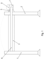
Figur 1 ist eine erfindungsgemäße Fördervorrichtung, insbesondere Bandfördereinrichtung oder Gurtförderer, mit einem direkt antreibenden Elektromotor schematisch dargestellt. - In der
Figur 2 ist ein Längsschnitt des Elektromotors schematisch dargestellt. - In der
Figur 3 ist eine Draufsicht auf den Elektromotor schematisch dargestellt. - Wie in den Figuren dargestellt, weist die Fördervorrichtung eine Vollwelle 4 auf, welche in einem ersten Tragteil 1 über ein Lager, insbesondere Wälzlager, drehbar gelagert ist.
- In einem vom ersten Tragteil 1 beabstandeten, zweiten Tragteil 2 ist ebenfalls ein zweites Lager zur drehbaren Lagerung der Vollwelle 4 angeordnet, wobei die Vollwelle 4 beidseitig dieses zweiten Lagers herausragt.
- Auf der vom ersten Tragteil 1 abgewandten Seite des zweiten Tragteils 2 ist der Elektromotor angeordnet.
- Hierzu ist ein Flansch 5 des Elektromotors mit dem zweiten Tragteil 2 schraubverbunden.
- An der vom zweiten Tragteil 2 abgewandten Seite ist ein Statorgehäuse 7 des Elektromotors mit dem Flansch 5 schraubverbunden.
- Ein Rotor 20 ist drehfest an einer Hohlwelle 21 angeordnet und mit ihr verbunden.
- Die Hohlwelle 21 ist über zwei im Statorgehäuse 7, insbesondere in zwei mit dem Statorgehäuse 7 verbundenen Lagerflanschen, aufgenommene Lager des Elektromotors drehbar gelagert.
- Die Hohlwelle 21 ist drehfest mit der Vollwelle 4 verbunden, insbesondere kraftschlüssig mittels einer Schrumpfschraube.
- Bei der Montage des mit dem Flansch 5 versehenen Elektromotors an das zweite Tragteil 2 werden Schraubteile, wie Verbindungsschrauben oder Gewindebolzen mit Schraubmuttern verwendet.
- Der Flansch 5 weist axial durchgehende Ausnehmungen auf, durch welche die Schraubteile hindurchragen. Allerdings ist in der jeweiligen Ausnehmung ein jeweiliges Federteil 30 angeordnet, das ringförmig ausgeformt ist. Das jeweilige Schraubteil ist durch ein jeweiliges Federteil 30 durchgeführt. Somit berühren die Schraubteile den Flansch 5 nicht direkt. Zwischen jedem schraubteil ist also ein jeweiliges Federteil 30 angeordnet.
- Vorzugsweise sind die Federteile 30 als Gummitülle ausgeführt.
- Bei der Montage des mit dem Flansch 5 versehenen Elektromotors an das zweite Tragteil 2 zentrieren die Federteile 30 den Elektromotor. Denn wichtig ist die koaxiale Ausrichtung der Vollwelle 4 zu der Hohlwelle 21. Zuerst wird also die Vollwelle 4 mit der Hohlwelle 21 verbunden und erst danach werden die Schraubteile mit Muttern festgeschraubt. Daher werden die Federteile 30 vor diesem Festschrauben schon verformt, um Toleranzen auszugleichen.
- Vorzugsweise weisen die Federteile 30 jeweils einen umlaufenden Kragen in einem ihrer axialen Endbereiche auf, so dass sie nur soweit in die axialen Bohrlöcher einsteckbar sind, bis der jeweilige Kragen anliegt. Somit begrenzt der jeweilige Kragen das jeweilige axiale Einstecken.
- Mit dem Statorgehäuse 7 ist ein Umrichter 6 verbunden, so dass der Elektromotor vom Umrichter drehzahlgeregelt oder drehmomentgeregelt betreibbar ist.
- Zwischen den beiden Tragteilen 1 und 2 ist eine Rolle 3 mit der Vollwelle 4 drehfest verbunden. Die Rolle 3 treibt vorzugsweise ein Band oder einen Gurt an.
- Der vom Flansch 5 überdeckte Radialabstandsbereich umfasst den von der Rolle 3 umfassten Radialabstandsbereich. Vorzugsweise ist er derart radial weiter ausgedehnt, dass die Schraubteile radial außerhalb der Rolle 3 verbindbar sind.
- Die axiale Richtung ist dabei parallel zur Drehachse der Vollwelle 4 ausgerichtet.
- Die Hohlwelle 21 mit einem Sackloch-artigen Hohlraum ausgeführt. Dies bedeutet, dass der Hohlraum der Hohlwelle 21 nicht durchgehend ausgeführt ist, sondern sacklochartig. Somit weist die Hohlwelle 21 an ihrem vom Flansch 5 abgewandten Endbereich einen Vollwellenbereich auf, der den angrenzenden Hohlwellenbereich verschließt. Somit ist eine erhöhte Schutzart erreichbar. Denn keinerlei Flüssigkeit kann aus dem Hohlraum in den Innenraum des Motors eintreten. Außerdem ist eine axiale Begrenzung für die in den Hohlwellenbereich eingesteckte Vollwelle 4 erreicht.
- Wie in
Figur 1 erkennbar, ist auch die seitliche Ausdehnung des Flansches 5 größer als die Ausdehnung des Umrichters 6 in dieser Richtung. Auf diese Weise sind die Schraubteile durch die durchgehenden Ausnehmungen der Federteile 30 und somit auch durch die die Federteile 30 aufnehmenden Axialbohrungen des Flansches 5 durchführbar. Die Betätigung der Schraubteile 30 ist daher vom Umrichter 6 ungestört und ungehindert ausführbar. Somit ist es vorteilhaft, dass die senkrechte Projektion der Federteile 30 auf eine Ebene, deren Normalenrichtung parallel zur Drehachse der Hohlwelle 21 des Elektromotors ausgerichtet ist, beabstandet ist von der senkrechten Projektion des Umrichters auf diese Ebene, insbesondere und sogar von der senkrechten Projektion des Statorgehäuses auf diese Ebene. - Vorzugsweise wird der Flansch 5 aus einem Material ausgeführt, das weicher ist, also ein höheres Elastizitätsmodul aufweist, als das Material des zweiten Tragteils 2 und härter ist, also ein niedrigeres Elastizitätsmodul aufweist, als die Federteile 30. Außerdem weist das Material bevorzugt eine höhere Wärmeleitfähigkeit auf als Stahl. Somit ist die vom Statorgehäuse 7 in den Flansch 5 fließende Wärme im Flansch 5 aufspreizbar und an das zweite Tragteil 2 weiterleitbar, das somit auch aus Stahl herstellbar ist. Denn der aufgespreizte Wärmestrom ist auch von einem schlechteren Wärmeleiter genügend gut aufnehmbar und an die Umgebung weiterleitbar.
- Vorzugsweise weist der Flansch 5 an seiner Außenseite Kühlrippen auf, die in axialer Richtung verlaufen.
- Die Hohlwelle 21 ist mittig durch den Flansch axial durchgeführt, ragt also axial beidseitig heraus.
- Der Flansch 5 ist dabei pyramidenförmig ausgeformt mit einer quadratischen Grundfläche.
- Wie in
Figur 3 gezeigt, ist der äußere Umfang der senkrechten Projektion des Flansches 5 in eine Ebene, deren Normale parallel zur axialen Richtung, also parallel zur Drehachse der Hohlwelle 21, ausgerichtet ist, ein Quadrat. - Bei weiteren erfindungsgemäßen Ausführungsbeispielen wird statt des sacklochartigen Hohlraums ein axial durchgehender Hohlraum verwendet. Die Hohlwelle 21 weist dann also einen axial durchgehenden zylindrischen Hohlraum auf, insbesondere wobei die Hohlwelle dann als Hohlzylinder ausgeführt ist. Somit ist eine kostengünstige Ausführung ermöglicht, bei welcher die Einstecktiefe der Vollwelle 4 nicht festgelegt ist.
- Bei weiteren erfindungsgemäßen Ausführungsbeispielen ist das axiale Ende der Hohlwelle 21 nicht in dem von dem Rotor 20 überdeckten axialen Bereich angeordnet, sondern der von der Hohlwelle 21 überdeckte axiale Bereich umfasst sogar den gesamten vom Rotor 20 überdeckten axialen Bereich. Insbesondere ragt also die Hohlwelle B-seitig insbesondere und A-seitig aus dem Elektromotor, insbesondere aus dessen Statorgehäuse 7, hervor.
- Wärme des Statorgehäuses ist über den Flansch auch ans zweite Tragteil 2 abführbar. Somit ist eine verbesserte Entwärmung des Motors erreichbar.
- Bei weiteren erfindungsgemäßen Ausführungsbeispielen wird das im zweiten Tragteil 2 aufgenommen Lager, also das zweite Lager, nicht vorgesehen, sondern die im Elektromotor angeordneten Lager der Hohlwelle 21 übernehmen nach Verbinden der Vollwelle 4 mit der Hohlwelle 21 auch die Lagerung der Vollwelle 4. Somit ist dann die Vollwelle 4 nur über das erste Lager, welches im ersten Tragteil 1 aufgenommen ist, und über die im Statorgehäuse 7 aufgenommenen Lager gelagert. Somit sind Verluste reduzierbar und insbesondere der Wärmeeintrag in das zweite Tragteil 2.
-
- 1 Tragteil
- 2 Tragteil
- 3 Rolle
- 4 Vollwelle
- 5 Flansch
- 6 Umrichter
- 7 Statorgehäuse
- 20 Rotor
- 21 Hohlwelle
- 30 Federteil, insbesondere Gummitülle
Claims (15)
- Fördervorrichtung mit einem ersten Tragteil (1), einem zweiten Tragteil (2), einem zwischen dem ersten und dem zweiten Tragteil (1, 2) angeordneten Fördermittel, insbesondere Rolle (3) oder Zahnrad, einer mit dem Fördermittel drehfest verbundenen Vollwelle (4) undeinem Elektromotor,wobei der Elektromotor ein Statorgehäuse (7) und einen Rotor (20) aufweist,wobei der Rotor (20) drehfest mit einer Hohlwelle (21) verbunden ist, welche relativ zum Statorgehäuse (7) drehbar gelagert ist,insbesondere wobei die Hohlwelle (21) mittels eines ersten Lagers, das in einem Lagerflansch aufgenommen ist und mit dem Statorgehäuse (7) verbunden ist, und mittels eines zweiten Lagers gelagert ist, das in einem zweiten Lagerflansch aufgenommen ist und mit dem Statorgehäuse (7) auf der von dem ersten Lagerflansch abgewandten Seite des Statorgehäuses (7) verbunden ist,wobei die Hohlwelle (21) drehfest, insbesondere kraftschlüssig, mit der Vollwelle (4) verbunden ist, welche zumindest teilweise in eine Ausnehmung der Hohlwelle (21) hineinragt,und wobei die Vollwelle (4) durch eine Ausnehmung des zweiten Tragteils (2) hindurchragt und in einem in dem ersten Tragteil (1) aufgenommenen ersten Lager drehbar gelagert ist,dadurch gekennzeichnet, dassdas Statorgehäuse (7), insbesondere der erste, mit dem Statorgehäuse (7) verbundene Lagerflansch, mit einem Flansch (5) verbunden ist, welcher auf der vom Elektromotor abgewandten Seite mit dem zweiten Tragteil (2) verbunden ist,dass der Flansch (5) mittels durch Ausnehmungen des Flansches (5) hindurchragender Schraubteile, insbesondere mittels durch Ausnehmungen des Flansches (5) hindurchragende Gewindestangen oder mittels durch Ausnehmungen des Flansches (5) hindurchragende Schraubenköpfe aufweisende Schrauben mit dem zweiten Tragteil (2) verbunden ist,dass jedes Schraubteil vom Flansch (5) beabstandet ist und das jeweilige Schraubteil durch ein jeweiliges Federteil (30) hindurchragt, das zwischen dem jeweiligen Schraubteil und dem Flansch (5) angeordnet ist,insbesondere wobei das jeweilige Federteil (30) in eine axial durch den Flansch (5) durchgehende Ausnehmung eingesteckt ist,und dass der Flansch (5) als Pyramidenstumpf mit einer quadratischen Grundfläche ausgeformt ist.
- Fördervorrichtung nach Anspruch 1, dadurch gekennzeichnet, dass der von der Hohlwelle (21) in axialer Richtung überdeckte Bereich den von dem Statorgehäuse (7) überdeckten Bereich umfasst.
- Fördervorrichtung nach Anspruch 1 oder 2,
dadurch gekennzeichnet, dass
im ersten Tragteil (1) ein zweites Lager zur drehbaren Lagerung der Vollwelle (4) angeordnet ist. - Fördervorrichtung nach einem der vorangegangenen Ansprüche,
dadurch gekennzeichnet, dass
das Federteil (30) aus einem elastischen Material, insbesondere aus einem Elastomer und/oder aus Gummi, gefertigt ist und/oder ringförmig ausgebildet ist. - Fördervorrichtung nach einem der vorangegangenen Ansprüche,
dadurch gekennzeichnet, dass
das Federteil (30) einen in Umfangsrichtung um die Ringachse des ringförmig ausgebildeten Federteils (30) umlaufenden, radial hervorragender Kragen aufweist, insbesondere radial am Federteil (30) hervorragenden Kragen. - Fördervorrichtung nach Anspruch 5
dadurch gekennzeichnet, dass
der Kragen das Federteil (30) in axialer Richtung am Flansch (5) begrenzt. - Fördervorrichtung nach einem der vorangegangenen Ansprüche,
dadurch gekennzeichnet, dass
der Flansch (5) aus einem Material, einstückig und/oder einteilig, hergestellt ist, dessen Elastizitätsmodul größer ist als das Elastizitätsmodul des zweiten Tragteils (2). - Fördervorrichtung nach einem der vorangegangenen Ansprüche,
dadurch gekennzeichnet, dass
die Hohlwelle (21) eine mittig angeordnete, sacklochartig ausgeführte Ausnehmung aufweist oder eine axial durch die Hohlwelle (21) durchgehende Bohrung aufweist. - Fördervorrichtung nach Anspruch 2, dadurch gekennzeichnet, dass die Hohlwelle (21) beidseitig in und entgegen der axialen Richtung aus dem Statorgehäuse (7) hervorragt.
- Fördervorrichtung nach einem der vorangegangenen Ansprüche,
dadurch gekennzeichnet, dass
das zweite Tragteil (2) aus Stahl und der Flansch (5) aus Aluminium gefertigt ist. - Fördervorrichtung nach einem der vorangegangenen Ansprüche,
dadurch gekennzeichnet, dass
die axial durch den Flansch (5) durchgehenden Ausnehmungen zur Aufnahme der Federteile (30) bilden ein quadratischen Bohrbild, insbesondere bei Blickrichtung in axialer Richtung. - Fördervorrichtung nach einem der vorangegangenen Ansprüche,
dadurch gekennzeichnet, dass
in einem jeweiligen Eckbereich des Quadrats ein jeweiliges Federteil (30) angeordnet ist. - Fördervorrichtung nach einem der vorangegangenen Ansprüche,
dadurch gekennzeichnet, dass
die senkrechte Projektion der Federteile (30) auf eine Ebene, deren Normalenrichtung parallel zur Drehachse der Hohlwelle (21) des Elektromotors ausgerichtet ist, beabstandet ist von der senkrechten Projektion des Statorgehäuses (7) auf diese Ebene. - Fördervorrichtung nach einem der vorangegangenen Ansprüche,
dadurch gekennzeichnet, dassein Umrichter (6) mit dem Statorgehäuse (7) verbunden ist,wobei die senkrechte Projektion der Federteile (30) auf eine Ebene, deren Normalenrichtung parallel zur Drehachse der Hohlwelle (21) des Elektromotors ausgerichtet ist, beabstandet ist von der senkrechten Projektion des Umrichters (6) auf diese Ebene. - Fördervorrichtung nach einem der vorangegangenen Ansprüche,
dadurch gekennzeichnet, dassam Flansch (5) Kühlrippen ausgeformt sind,
und/oder dassder Rotor (20) des Elektromotors mit Dauermagneten bestückt ist
und/oder dassder Elektromotor ein Synchronmotor ist,
und/oder dasssich die Kühlrippen des Flansches (5) axial erstrecken und bezogen auf die Drehachse der Vollwelle (4) in Umfangsrichtung gleichmäßig voneinander beabstandet sind,insbesondere wobei allerdings in dem von dem jeweiligen Federteil (30), insbesondere von dessen Kragen, überdeckten Umfangswinkelbereich keine Kühlrippen angeordnet sind sondern in dem von den Kühlrippen in axialer Richtung überdeckten Bereich der vom Flansch (5) überdeckte Radialabstandsbereich kleiner ist als und/oder beabstandet ist von dem von den Federteil (30)en überdeckten Radialabstandsbereich.
Applications Claiming Priority (3)
| Application Number | Priority Date | Filing Date | Title |
|---|---|---|---|
| US201962872931P | 2019-07-11 | 2019-07-11 | |
| DE102019005068 | 2019-07-22 | ||
| PCT/EP2020/025305 WO2021004656A1 (de) | 2019-07-11 | 2020-06-29 | Fördervorrichtung mit einem elektromotor |
Publications (3)
| Publication Number | Publication Date |
|---|---|
| EP3997018A1 EP3997018A1 (de) | 2022-05-18 |
| EP3997018C0 EP3997018C0 (de) | 2024-08-07 |
| EP3997018B1 true EP3997018B1 (de) | 2024-08-07 |
Family
ID=71465281
Family Applications (1)
| Application Number | Title | Priority Date | Filing Date |
|---|---|---|---|
| EP20736575.0A Active EP3997018B1 (de) | 2019-07-11 | 2020-06-29 | Fördervorrichtung mit einem elektromotor |
Country Status (6)
| Country | Link |
|---|---|
| US (1) | US12088178B2 (de) |
| EP (1) | EP3997018B1 (de) |
| CN (1) | CN114080747B (de) |
| CA (1) | CA3147511A1 (de) |
| DE (1) | DE102020003871A1 (de) |
| WO (1) | WO2021004656A1 (de) |
Family Cites Families (14)
| Publication number | Priority date | Publication date | Assignee | Title |
|---|---|---|---|---|
| US3918574A (en) * | 1974-10-07 | 1975-11-11 | Cutler Hammer Inc | Multiple D.C. permanent magnet motor drive for belt type conveyors |
| CN2452826Y (zh) | 2000-11-21 | 2001-10-10 | 欧阳建根 | 一种用于矿车的缓冲器 |
| JP2004083179A (ja) | 2002-08-26 | 2004-03-18 | Watanabe Kikai Seisakusho:Kk | 搬送装置 |
| US7537107B2 (en) * | 2006-11-17 | 2009-05-26 | Milwaukee Electronics Corporation | External direct drive for a roller conveyor |
| CN201713737U (zh) | 2010-05-28 | 2011-01-19 | 安徽省巢湖铸造厂有限责任公司 | 一种铁路高弹性减振降噪扣件 |
| DE102010051192B4 (de) | 2010-11-15 | 2012-12-06 | Sew-Eurodrive Gmbh & Co. Kg | Fördervorrichtung, Antrieb und Herstellverfahren für eine Fördervorrichtung |
| CN201925304U (zh) | 2011-02-17 | 2011-08-10 | 潘体森 | 一种螺塞 |
| PL2562102T3 (pl) | 2011-08-23 | 2014-09-30 | Siemens Ag | Przenośnik taśmowy, sposób jego eksploatacji oraz jego zastosowanie |
| DE102015210641A1 (de) | 2015-06-10 | 2016-12-15 | Baumüller Nürnberg GmbH | Antrieb |
| US10411562B2 (en) * | 2016-01-14 | 2019-09-10 | Honeywell International Inc. | Compact high speed generator having passageways for air and cooling oil |
| US10017325B2 (en) | 2016-03-21 | 2018-07-10 | Kamran Ramezani | Hollow shaft direct drive motor |
| CN207080477U (zh) | 2017-07-12 | 2018-03-09 | 泰州市得尔机电制造有限公司 | 一种接线箱下壳盖用防掉落螺栓总成 |
| TWI672892B (zh) * | 2018-06-22 | 2019-09-21 | 群光電能科技股份有限公司 | 馬達套筒及馬達裝置 |
| CN111824695B (zh) * | 2019-04-17 | 2024-09-06 | 梅特勒-托利多安全线有限公司 | 用于输送机系统的驱动辊组件和包括它的输送机系统 |
-
2020
- 2020-06-29 US US17/626,172 patent/US12088178B2/en active Active
- 2020-06-29 CN CN202080049900.9A patent/CN114080747B/zh active Active
- 2020-06-29 CA CA3147511A patent/CA3147511A1/en active Pending
- 2020-06-29 DE DE102020003871.9A patent/DE102020003871A1/de active Pending
- 2020-06-29 EP EP20736575.0A patent/EP3997018B1/de active Active
- 2020-06-29 WO PCT/EP2020/025305 patent/WO2021004656A1/de not_active Ceased
Also Published As
| Publication number | Publication date |
|---|---|
| WO2021004656A1 (de) | 2021-01-14 |
| US12088178B2 (en) | 2024-09-10 |
| US20220320952A1 (en) | 2022-10-06 |
| EP3997018A1 (de) | 2022-05-18 |
| CN114080747A (zh) | 2022-02-22 |
| CN114080747B (zh) | 2024-04-19 |
| DE102020003871A1 (de) | 2021-01-14 |
| EP3997018C0 (de) | 2024-08-07 |
| CA3147511A1 (en) | 2021-01-14 |
Similar Documents
| Publication | Publication Date | Title |
|---|---|---|
| EP2241781B2 (de) | Getriebe, insbesondere Planetengetriebe mit einem Flansch und einem Hohlrad | |
| DE10143386B4 (de) | Parksperre für ein Kraftfahrzeug | |
| DE102019209470B4 (de) | Parksperrenanordnung mit Parksperrenrad und Torsionsdämpfer | |
| DE102016219919A1 (de) | Elastisches Zahnrad eines Wellgetriebes | |
| DE102016216274A1 (de) | Riemenscheibenentkoppler mit Doppelnabe | |
| WO2020098859A1 (de) | Bremssystem, achsträgereinheit für ein fahrzeug, fahrzeug mit einer derartigen achsträgereinheit und antriebseinheit | |
| WO2014135246A1 (de) | Getriebemotoranordnung | |
| DE3104201C2 (de) | Riemenspannvorrichtung | |
| DE3827249A1 (de) | Nachgiebige mitnehmerscheibe | |
| DE102015115001B4 (de) | Riemenscheiben-Baugruppe | |
| EP3997018B1 (de) | Fördervorrichtung mit einem elektromotor | |
| DE102013210074A1 (de) | Antriebseinrichtung | |
| DE102011105020A1 (de) | Torsionsschwingungsdämpfer | |
| DE102012005529B4 (de) | Antrieb mit einer Welle | |
| EP3947998B1 (de) | Spannverbindung mit einem auf einer nabe, insbesondere hohlwellenabschnitt, aufgesteckten spannring mit schraube, insbesondere spannschraube | |
| DE102022129231A1 (de) | Antrieb und Verfahren zur Montage eines Antriebs | |
| DE102010062325A1 (de) | Riemenantrieb mit Torsionsdämpfer | |
| EP0826884A2 (de) | Lüfter | |
| WO2001055621A2 (de) | Mitnehmerscheibe zur moment-übertragung von einer antriebseinheit auf einen hydrodynamischen wandler | |
| EP3948000B1 (de) | Spannverbindung mit einem auf einer nabe, insbesondere hohlwellenabschnitt, aufgesteckten spannring mit schraube, insbesondere spannschraube | |
| EP4352374B1 (de) | Anordnung mit einer welle, einem auf die welle aufgesteckten innenring eines lagers und einer mit der welle verbundenen nabe | |
| EP0481268A1 (de) | Torsionsschwingungsdämpferanordnung | |
| DE102004014886B4 (de) | Transportsicherung für eine Brennkraftmaschine | |
| EP3947999A1 (de) | Spannverbindung mit einem auf einer nabe, insbesondere hohlwellenabschnitt, aufgesteckten spannring mit schraube, insbesondere spannschraube | |
| DE19653654A1 (de) | Lagerung einer Antriebsachse |
Legal Events
| Date | Code | Title | Description |
|---|---|---|---|
| STAA | Information on the status of an ep patent application or granted ep patent |
Free format text: STATUS: UNKNOWN |
|
| STAA | Information on the status of an ep patent application or granted ep patent |
Free format text: STATUS: THE INTERNATIONAL PUBLICATION HAS BEEN MADE |
|
| PUAI | Public reference made under article 153(3) epc to a published international application that has entered the european phase |
Free format text: ORIGINAL CODE: 0009012 |
|
| STAA | Information on the status of an ep patent application or granted ep patent |
Free format text: STATUS: REQUEST FOR EXAMINATION WAS MADE |
|
| 17P | Request for examination filed |
Effective date: 20220211 |
|
| AK | Designated contracting states |
Kind code of ref document: A1 Designated state(s): AL AT BE BG CH CY CZ DE DK EE ES FI FR GB GR HR HU IE IS IT LI LT LU LV MC MK MT NL NO PL PT RO RS SE SI SK SM TR |
|
| DAV | Request for validation of the european patent (deleted) | ||
| DAX | Request for extension of the european patent (deleted) | ||
| GRAP | Despatch of communication of intention to grant a patent |
Free format text: ORIGINAL CODE: EPIDOSNIGR1 |
|
| STAA | Information on the status of an ep patent application or granted ep patent |
Free format text: STATUS: GRANT OF PATENT IS INTENDED |
|
| INTG | Intention to grant announced |
Effective date: 20240320 |
|
| GRAS | Grant fee paid |
Free format text: ORIGINAL CODE: EPIDOSNIGR3 |
|
| GRAA | (expected) grant |
Free format text: ORIGINAL CODE: 0009210 |
|
| STAA | Information on the status of an ep patent application or granted ep patent |
Free format text: STATUS: THE PATENT HAS BEEN GRANTED |
|
| AK | Designated contracting states |
Kind code of ref document: B1 Designated state(s): AL AT BE BG CH CY CZ DE DK EE ES FI FR GB GR HR HU IE IS IT LI LT LU LV MC MK MT NL NO PL PT RO RS SE SI SK SM TR |
|
| REG | Reference to a national code |
Ref country code: GB Ref legal event code: FG4D Free format text: NOT ENGLISH |
|
| REG | Reference to a national code |
Ref country code: CH Ref legal event code: EP |
|
| REG | Reference to a national code |
Ref country code: DE Ref legal event code: R096 Ref document number: 502020008809 Country of ref document: DE |
|
| REG | Reference to a national code |
Ref country code: IE Ref legal event code: FG4D Free format text: LANGUAGE OF EP DOCUMENT: GERMAN |
|
| U01 | Request for unitary effect filed |
Effective date: 20240812 |
|
| U07 | Unitary effect registered |
Designated state(s): AT BE BG DE DK EE FI FR IT LT LU LV MT NL PT SE SI Effective date: 20240819 |
|
| PG25 | Lapsed in a contracting state [announced via postgrant information from national office to epo] |
Ref country code: NO Free format text: LAPSE BECAUSE OF FAILURE TO SUBMIT A TRANSLATION OF THE DESCRIPTION OR TO PAY THE FEE WITHIN THE PRESCRIBED TIME-LIMIT Effective date: 20241107 |
|
| PG25 | Lapsed in a contracting state [announced via postgrant information from national office to epo] |
Ref country code: GR Free format text: LAPSE BECAUSE OF FAILURE TO SUBMIT A TRANSLATION OF THE DESCRIPTION OR TO PAY THE FEE WITHIN THE PRESCRIBED TIME-LIMIT Effective date: 20241108 Ref country code: PL Free format text: LAPSE BECAUSE OF FAILURE TO SUBMIT A TRANSLATION OF THE DESCRIPTION OR TO PAY THE FEE WITHIN THE PRESCRIBED TIME-LIMIT Effective date: 20240807 |
|
| PG25 | Lapsed in a contracting state [announced via postgrant information from national office to epo] |
Ref country code: IS Free format text: LAPSE BECAUSE OF FAILURE TO SUBMIT A TRANSLATION OF THE DESCRIPTION OR TO PAY THE FEE WITHIN THE PRESCRIBED TIME-LIMIT Effective date: 20241207 |
|
| PG25 | Lapsed in a contracting state [announced via postgrant information from national office to epo] |
Ref country code: HR Free format text: LAPSE BECAUSE OF FAILURE TO SUBMIT A TRANSLATION OF THE DESCRIPTION OR TO PAY THE FEE WITHIN THE PRESCRIBED TIME-LIMIT Effective date: 20240807 |
|
| PG25 | Lapsed in a contracting state [announced via postgrant information from national office to epo] |
Ref country code: RS Free format text: LAPSE BECAUSE OF FAILURE TO SUBMIT A TRANSLATION OF THE DESCRIPTION OR TO PAY THE FEE WITHIN THE PRESCRIBED TIME-LIMIT Effective date: 20241107 Ref country code: ES Free format text: LAPSE BECAUSE OF FAILURE TO SUBMIT A TRANSLATION OF THE DESCRIPTION OR TO PAY THE FEE WITHIN THE PRESCRIBED TIME-LIMIT Effective date: 20240807 |
|
| PG25 | Lapsed in a contracting state [announced via postgrant information from national office to epo] |
Ref country code: RS Free format text: LAPSE BECAUSE OF FAILURE TO SUBMIT A TRANSLATION OF THE DESCRIPTION OR TO PAY THE FEE WITHIN THE PRESCRIBED TIME-LIMIT Effective date: 20241107 Ref country code: PL Free format text: LAPSE BECAUSE OF FAILURE TO SUBMIT A TRANSLATION OF THE DESCRIPTION OR TO PAY THE FEE WITHIN THE PRESCRIBED TIME-LIMIT Effective date: 20240807 Ref country code: NO Free format text: LAPSE BECAUSE OF FAILURE TO SUBMIT A TRANSLATION OF THE DESCRIPTION OR TO PAY THE FEE WITHIN THE PRESCRIBED TIME-LIMIT Effective date: 20241107 Ref country code: IS Free format text: LAPSE BECAUSE OF FAILURE TO SUBMIT A TRANSLATION OF THE DESCRIPTION OR TO PAY THE FEE WITHIN THE PRESCRIBED TIME-LIMIT Effective date: 20241207 Ref country code: HR Free format text: LAPSE BECAUSE OF FAILURE TO SUBMIT A TRANSLATION OF THE DESCRIPTION OR TO PAY THE FEE WITHIN THE PRESCRIBED TIME-LIMIT Effective date: 20240807 Ref country code: GR Free format text: LAPSE BECAUSE OF FAILURE TO SUBMIT A TRANSLATION OF THE DESCRIPTION OR TO PAY THE FEE WITHIN THE PRESCRIBED TIME-LIMIT Effective date: 20241108 Ref country code: ES Free format text: LAPSE BECAUSE OF FAILURE TO SUBMIT A TRANSLATION OF THE DESCRIPTION OR TO PAY THE FEE WITHIN THE PRESCRIBED TIME-LIMIT Effective date: 20240807 |
|
| PG25 | Lapsed in a contracting state [announced via postgrant information from national office to epo] |
Ref country code: SM Free format text: LAPSE BECAUSE OF FAILURE TO SUBMIT A TRANSLATION OF THE DESCRIPTION OR TO PAY THE FEE WITHIN THE PRESCRIBED TIME-LIMIT Effective date: 20240807 |
|
| PG25 | Lapsed in a contracting state [announced via postgrant information from national office to epo] |
Ref country code: CZ Free format text: LAPSE BECAUSE OF FAILURE TO SUBMIT A TRANSLATION OF THE DESCRIPTION OR TO PAY THE FEE WITHIN THE PRESCRIBED TIME-LIMIT Effective date: 20240807 |
|
| PG25 | Lapsed in a contracting state [announced via postgrant information from national office to epo] |
Ref country code: SK Free format text: LAPSE BECAUSE OF FAILURE TO SUBMIT A TRANSLATION OF THE DESCRIPTION OR TO PAY THE FEE WITHIN THE PRESCRIBED TIME-LIMIT Effective date: 20240807 |
|
| PLBE | No opposition filed within time limit |
Free format text: ORIGINAL CODE: 0009261 |
|
| STAA | Information on the status of an ep patent application or granted ep patent |
Free format text: STATUS: NO OPPOSITION FILED WITHIN TIME LIMIT |
|
| PGFP | Annual fee paid to national office [announced via postgrant information from national office to epo] |
Ref country code: GB Payment date: 20250508 Year of fee payment: 6 |
|
| 26N | No opposition filed |
Effective date: 20250508 |
|
| U20 | Renewal fee for the european patent with unitary effect paid |
Year of fee payment: 6 Effective date: 20250630 |
|
| REG | Reference to a national code |
Ref country code: CH Ref legal event code: H13 Free format text: ST27 STATUS EVENT CODE: U-0-0-H10-H13 (AS PROVIDED BY THE NATIONAL OFFICE) Effective date: 20260127 |
|
| PG25 | Lapsed in a contracting state [announced via postgrant information from national office to epo] |
Ref country code: MC Free format text: LAPSE BECAUSE OF FAILURE TO SUBMIT A TRANSLATION OF THE DESCRIPTION OR TO PAY THE FEE WITHIN THE PRESCRIBED TIME-LIMIT Effective date: 20240807 |
|
| PG25 | Lapsed in a contracting state [announced via postgrant information from national office to epo] |
Ref country code: IE Free format text: LAPSE BECAUSE OF NON-PAYMENT OF DUE FEES Effective date: 20250629 |
|
| PG25 | Lapsed in a contracting state [announced via postgrant information from national office to epo] |
Ref country code: RO Free format text: LAPSE BECAUSE OF FAILURE TO SUBMIT A TRANSLATION OF THE DESCRIPTION OR TO PAY THE FEE WITHIN THE PRESCRIBED TIME-LIMIT Effective date: 20240807 |