EP3997271B1 - Système et procédé d'inspection et de maintenance de pont - Google Patents
Système et procédé d'inspection et de maintenance de pont Download PDFInfo
- Publication number
- EP3997271B1 EP3997271B1 EP20758343.6A EP20758343A EP3997271B1 EP 3997271 B1 EP3997271 B1 EP 3997271B1 EP 20758343 A EP20758343 A EP 20758343A EP 3997271 B1 EP3997271 B1 EP 3997271B1
- Authority
- EP
- European Patent Office
- Prior art keywords
- bridge
- parts
- structures
- longitudinal axis
- maintenance
- Prior art date
- Legal status (The legal status is an assumption and is not a legal conclusion. Google has not performed a legal analysis and makes no representation as to the accuracy of the status listed.)
- Active
Links
Images



Classifications
-
- E—FIXED CONSTRUCTIONS
- E01—CONSTRUCTION OF ROADS, RAILWAYS, OR BRIDGES
- E01D—CONSTRUCTION OF BRIDGES, ELEVATED ROADWAYS OR VIADUCTS; ASSEMBLY OF BRIDGES
- E01D19/00—Structural or constructional details of bridges
- E01D19/10—Railings; Protectors against smoke or gases, e.g. of locomotives; Maintenance travellers; Fastening of pipes or cables to bridges
- E01D19/106—Movable inspection or maintenance platforms, e.g. travelling scaffolding or vehicles specially designed to provide access to the undersides of bridges
-
- E—FIXED CONSTRUCTIONS
- E04—BUILDING
- E04G—SCAFFOLDING; FORMS; SHUTTERING; BUILDING IMPLEMENTS OR AIDS, OR THEIR USE; HANDLING BUILDING MATERIALS ON THE SITE; REPAIRING, BREAKING-UP OR OTHER WORK ON EXISTING BUILDINGS
- E04G3/00—Scaffolds essentially supported by building constructions, e.g. adjustable in height
- E04G3/28—Mobile scaffolds; Scaffolds with mobile platforms
- E04G2003/283—Mobile scaffolds; Scaffolds with mobile platforms mobile horizontally
-
- E—FIXED CONSTRUCTIONS
- E04—BUILDING
- E04G—SCAFFOLDING; FORMS; SHUTTERING; BUILDING IMPLEMENTS OR AIDS, OR THEIR USE; HANDLING BUILDING MATERIALS ON THE SITE; REPAIRING, BREAKING-UP OR OTHER WORK ON EXISTING BUILDINGS
- E04G3/00—Scaffolds essentially supported by building constructions, e.g. adjustable in height
- E04G3/28—Mobile scaffolds; Scaffolds with mobile platforms
Definitions
- the present invention relates to a bridge inspection and maintenance system, comprising a mounted sliding platform below the bridge to be inspected.
- the platform further comprises one or more sensors for acquiring images of said bridge.
- the inspection of bridges generally takes place by monitoring the condition of the bridge parts, especially the parts below the bridge, using visual investigation methods and non-destructive testing, imaging means, such as cameras or the like, so that the processing of the acquired images allows to identify any structural defects or to predict breakages or damage to the bridge structure.
- the inspection of the bridge by visual inspection means is of great help for highlighting any damage in the initial phases of construction and during normal use of the bridge, but also for verifying the conformity of welds and geometry with respect to the project designs, immediately after construction.
- Some current systems provide for automated monitoring and inspection, using robotic means, presenting different solutions related to small or large systems.
- Some state-of-the-art robotic solutions include the development of a mobile and autonomous manipulator for the maintenance of steel bridges, which allows the removal of paint and rust.
- This system consists of a platform adapted to support the manipulator, a computer, a laser scanner and several sensors. In this way the system can inspect the bridge and detect any defects.
- the rails on which the platform moves are part of the system and not of the bridge, which has negative repercussions on portability. Furthermore, since the platform is connected to the ground and not to the bridge to be monitored, the vibrations due to the vehicle traffic transiting on the bridge generate incorrect images, which do not correspond to the actual situation of the bridge and which cannot be reprocessed for proper inspection and possible intervention.
- Lightweight and portable robots are also present in the state of the art, designed to allow the inspection of bridges.
- Such systems are designed so that operators can easily carry such robots and use them through the use of a lifting system, such as for example a ladder, a crane, at the point to be monitored.
- a lifting system such as for example a ladder, a crane, at the point to be monitored.
- These systems equipped with a high-resolution camera, provide the operator with rapid information that can be immediately used to assess the condition of the bridge.
- this type of solution cannot be used on very high bridges or those which are not easily accessible.
- the robotic system although capable of overcoming minimal obstacles, cannot bypass the bridge piers and, if necessary, must be moved manually.
- a continuous and systematic scan not only allows to plan maintenance when a problem is detected, but also to predict the formation of defects in the bridge structure, thanks to the analysis of the data collected.
- the present invention achieves the above aims by realizing a system as defined in claim 1, in which the platform is formed by two structures positioned symmetrically with respect to the longitudinal axis of the bridge.
- each structure comprises a first part configured to translate along a longitudinal axis of the bridge on a corresponding longitudinal guide integral with the bridge and a second part configured to transversely translate with respect to said longitudinal axis on the first part on a corresponding transverse guide.
- the two structures can be moved from a closed configuration, in which the corresponding second parts are coupled to each other at the central longitudinal axis of the bridge, to an open configuration, in which the two second parts are separated from each other in the opposite direction with respect to the centre of the central longitudinal axis of the bridge, until they are decoupled from each other, by a transverse translational movement.
- the system object of the present invention allows carrying out inspections of the areas below the bridges in a continuous and rapid manner.
- Imaging sensors such as cameras, therefore detect precise images of the bridge structure, so as not only to obtain constant and effective monitoring, but also to identify the current state of maintenance and obtain a prediction about future interventions, necessary to prevent possible damage.
- the system object of the present invention does not require any type of support structures for the mounting on the bridge or for the operation thereof: it is therefore possible to carry out continuous monitoring, also during normal use conditions of the bridge by vehicles.
- the two second parts form a single platform, capable of supporting further robotic means for the cleaning, thorough inspection and/or maintenance of the bridge.
- the two structures can switch from the closed configuration to the open configuration whenever they are located at a bridge pier or whenever necessary, so that the first parts can slide independently without the obstruction of the piers and without interrupting the monitoring of the bridge.
- system object of the present invention is preferably realized for automatic operation, possibly under the supervision of a user who controls the system remotely.
- the system is integral with the bridge, so in combination with the latter, it allows the realization of a sort of "smart bridge”, that is, a bridge which comprises sensors aimed at detecting structural anomalies and which can process structural information to allow the real-time monitoring of the bridge status and predict future damage.
- a sort of "smart bridge” that is, a bridge which comprises sensors aimed at detecting structural anomalies and which can process structural information to allow the real-time monitoring of the bridge status and predict future damage.
- each second part has an upper guide adapted to support robotic inspection and/or maintenance and/or cleaning means.
- the upper guides identify a single upper guide.
- the system object of the present invention is therefore able to collect data from the sensors incorporated into the structure on a very rapid regular basis when in open configuration, at the same time, it is able to offer support to other robotic devices which perform dedicated and more accurate inspections, maintenance and cleaning, when in closed configuration.
- Robotic vehicles can, of course, offer a wide range of machining which can be carried out on the bridge, depending on the tools which are provided on these robotic vehicles.
- the ends of said second parts facing the central longitudinal axis of the bridge have complementary profiles, so that in a coupled configuration of the two second parts, the profiles of the corresponding ends are in contact by shape coupling.
- a mechanical, shape coupling system is used, simple from a constructive point of view and particularly solid without the need to use electronic devices, which can be damaged during the movement of the parts or increase the risk of breakages or malfunctions of the entire system.
- one end has a convex profile along a vertical section plane in the direction of the centre of the bridge, while the other end has a concave profile along a vertical section plane in the direction of the centre of the bridge.
- the convex, or pointed, end encompasses the other as one second portion approaches the other.
- the interpenetration of one end with the other allows to obtain a perfect coupling of the parts, in order to achieve a precise alignment of the upper guides, for an easy transition from one part of the robotic means to the other.
- the longitudinal guides are arranged at the sides of the bridge.
- the second portions are arranged lower than the first portions.
- This configuration also facilitates the movement of the second parts, as their dimensions do not create obstacles to the movement of the same with respect to the first parts.
- the system in closed configuration, is able to use robotic means to perform specific machining and to obtain more accurate images.
- the present invention also relates to a method of bridge inspection and maintenance, as defined in claim 6 and which provides for the use of the system described above.
- the method object of the present invention comprises the following steps:
- the two structures which move separately in open configuration, can scan the parts below the bridge at high speed, collect these images and process them.
- the two structures can perform translations and imaging of the bridge at different times and/or in different bridge areas.
- the step a) of translation takes place so that the two structures can move independently and non-aligned, so as to monitor different sections of the bridge positioned along the longitudinal axis thereof.
- the first parts can therefore only deal with the movement of the structures, while the second parts deal with the detection of images, thanks to the presence of the sensors.
- the processing means may be provided integrated within the first or second portions, or may be provided remotely, connected to the structures via wireless communication.
- both structures may be positioned at said areas and the second parts may be coupled, so as to form a single platform.
- the method object of the present invention is a method of controlling the inspection system described above, whereby, according to this method, the transition from the open configuration to the closed configuration and vice versa is carried out not only to allow the formation of a single support platform for further robotic means operating on the parts below the bridge, but whenever the two structures are located at a pier.
- Such embodiments are therefore for illustrative purposes only and not limited to the inventive concept of the present invention, that is, of realizing a bridge inspection system, which allows a continuous monitoring of the bridge conditions and which allows an acquisition of images of the bridge to be inspected which are not affected by the traffic of vehicles transiting on the bridge, ensuring a rapid and effective acquisition.
- the bridge inspection and maintenance system 10 comprises two structures 1, 2 positioned symmetrically with respect to the longitudinal axis A of the bridge 10 which are slidably mounted below the bridge 10.
- the two structures 1, 2 further comprise one or more sensors for acquiring images of the bridge 10.
- Such sensors are not illustrated in the figure, but may consist of common imaging sensors, such as video cameras, photo cameras or the like, and are integrated within the two structures 1 and 2.
- Such sensors thus allow images of the bridge 10 to be acquired, in particular of the areas below the roadway of the bridge 10, which can be more easily damaged.
- the translation of the two structures 1 and 2 along the direction of the longitudinal axis A of the bridge 10 therefore allows to acquire images of the entire area below the roadway of the bridge 10.
- each structure is symmetrical with respect to the longitudinal axis A of the bridge, and each structure comprises a first part, respectively 11 and 21, and a second part, respectively 12 and 22.
- the first parts 11 and 21 are configured to move along a longitudinal axis of the bridge 10 on a corresponding longitudinal guide 13, 23, integral with the bridge 10.
- the longitudinal guides 13 and 23 are positioned at the sides of the bridge 10, as clearly illustrated in figures 1b and 2b .
- each second part 12 and 22 is configured to translate transversely with respect to the longitudinal axis A, on the corresponding first part 11, 21 through a transverse guide, illustrated and described below in figure 3 .
- each structure 1 and 2 moves in the directions indicated by arrows B and C of figures 1b and 2b .
- first parts 11 and 21 move along the entire length of the bridge 10, arrow B, while the second parts 12 and 22 provide for a mutual approach/distancing movement, arrow C.
- the movement of the second parts 12 and 22 allows to identify a closed configuration, in which the second parts 12 and 22 are in a configuration coupled to each other, to an open configuration, in which the two second parts 12 and 22, sliding transversely in the opposite direction with respect to the axis A, are decoupled from each other.
- FIGS 1a and 1b illustrate the open configuration, while figures 2a and 2b illustrate the closed configuration.
- one of the criteria for switching from the closed configuration to the open configuration is the presence of a pier 100 of the bridge 10.
- the two structures 1 and 2 are located at a pier 100: in order to allow the two structures to slide longitudinally, the two second parts 12 and 22 slide transversely towards the sides of the bridge 10, so that the two structures 1 and 2 can translate laterally with respect to the pier 100.
- the two structures 1 and 2 can be independently controlled, to monitor different parts of the bridge 10, positioned in a different longitudinal direction.
- first parts 11 and 21 preferably are small compared to the second parts 12 and 22.
- the first parts 11 and 21 act as a support for the second parts 12 and 22, with the sole purpose of allowing the latter to be dragged in the direction of the longitudinal axis A of the bridge 10.
- each second part 12, 22 instead comprise the imaging sensors and, according to a preferred embodiment, each second part 12, 22 has an upper guide adapted to support robotic means of inspection, and/or maintenance and/or cleaning.
- the upper guides identify a single upper guide.
- the longitudinal guides of the first parts 11, 21, the transverse guides of the second parts 12, 22 and the upper guides may be realized in any of the ways known in the state of the art.
- Figure 3 illustrates a possible embodiment of such guides.
- FIG 3 a view of one of the two structures is illustrated, e.g., of the structure 1, in which the first part 11 and the second part 12 are provided.
- the second part 12 has two transverse guides 122 adapted to allow the movement of the second part 12 with respect to the first part 11 (arrow C) and an upper guide 123 adapted to support robotic means of inspection, and/or maintenance and/or cleaning, not illustrated in the figure.
- the sliding of the first parts 11, 21 on the longitudinal guides positioned along the sides of the bridge 10 can take place thanks to standard means such as wheels or cables.
- the longitudinal guides can simply be realized with standard steel profiles.
- the robotic means slide through another rack 123 fixed to the second parts 12, 22, on which a sprocket connected to said robotic means is fixed.
- the robotic means can be of different nature: they can be dedicated to inspection tests, for example by providing additional cameras with respect to the sensors of the second parts, cleaning or other maintenance work.
- the robotic means are moved from one side to the other of the bridge 10 (i.e., the second parts 12, 22) in a standard manner, thanks to the perfect continuity of the upper guides 123 positioned on the second parts.
- the system object of the present invention is generally fully automatic, but is also manually operable, through specific tools, if the emergency recovery of the system is necessary.
- the system object of the present invention is fully automatic and/or operated remotely, and the remote supervision of one or more operators can be provided.
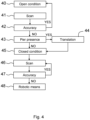
- FIG. 4 An embodiment of the bridge inspection method of the present invention is illustrated in figure 4 .
- This method involves the use of the system described above.
- step 40 these structures are moved, separately or in combination, in the area below the main roadway of the bridge to be inspected.
- the scan takes place, step 41, through the sensors positioned on the structures 1 and 2.
- the scan performed by the structures 1 and 2 in open configuration is carried out quickly, thanks to the speed of movement of the two structures 1 and 2.
- the data acquired during the scan, step 41, is collected and can be processed through artificial intelligence algorithms, which can be used both to identify the bridge status and to predict future interventions.
- step 42 an analysis of the data collected in step 41 is performed to verify the presence of problems which require more accurate maintenance or investigation. In the absence of these problems, the scanning continues on another area of the bridge always in open configuration.
- two different areas of the bridge can be inspected, speeding up the monitoring of the same, concentrating the inspection of both structures only at points identified as particularly deteriorated, or requiring maintenance.
- the second parts 12 and 22 are moved transversely, until they reach the coupled configuration and the corresponding closed configuration, step 45, of the structures 1 and 2.
- the two structures 1 and 2 must first be aligned, to allow the second parts to be configured in closed condition.
- step 46 Such configuration allows a single platform to be formed capable of supporting further robotic means, step 46, which perform more accurate inspections, maintenance and/or cleaning depending on the problems detected in step 42.
- step 45 the system detects if it is located at a pier, which would not allow the movement of the second parts towards the central longitudinal axis of the bridge.
- the detection of a pier may, for example, be carried out with proximity sensors.
- step 44 the two structures 1 and 2 are moved, step 44, up to a distance from the pier such that the second parts 12 and 22, step 45, can be coupled and then operated with robotic means, step 46.
- Step 48 relating to the use of robotic means is carried out not only to increase the accuracy of the images, but also if the previous scans of steps 41 and 46 have detected certain processes to be carried out on the bridge.
- Figures 5a and 5b illustrate two views of the second parts 12 and 22 in coupled configuration, with the detail of the ends of each second part facing the centre of the bridge.
- the second part 12 is realized in a manner completely similar to the second part 22, except for the contact ends in coupling configuration, which identify the interface 220.
- such ends of the said second parts have complementary profiles, so that in coupled configuration of the second parts 12 and 22, the profiles of the corresponding ends are in contact by shape coupling.
- the end of the second part 12 has a convex profile 222, along a vertical section plane, in the direction of the central longitudinal axis of the bridge 10, while the other end has a concave profile 221, along a vertical section plane, in the direction of the centre of the bridge 10.
- the profiles 221 and 222 therefore have a wedge-shaped section, such that, in the transition from the decoupled configuration to the coupled configuration, the outer walls of the profile 222 slide against the outer walls of the profile 221, up to the interpenetration of the vertex of the profile 222 into the seat formed by the concave profile 221.
- the variant just described makes it possible to realize a system which has a particularly slim structure and easy handling.
- the second parts 12 and 22 can slide on the first parts 11 and 21, which are hung on the guides 13 and 23 and do not require additional components for the correct maintenance in position of the second or first parts.
- the curved shape of the second parts 12 and 22 allows to limit the dimensions of the latter, also in open condition, when the second parts are more spaced apart from each other
- the curved shape of the second parts 21 and 22 also has advantageous aspects with respect to the translation, especially in combination with the presence of complementary surfaces as described with regard to figures 5a and 5b , as it facilitates the coupling of the two second parts 12 and 22.
- the translation along a curve, and not along a straight line, of the two second parts facilitates the sliding of the surface 222 on the surface 221, ensuring a solid coupling of the two second parts, even in the event of jolts in one or the other part, during the transition from the open condition to the closed condition.
Landscapes
- Engineering & Computer Science (AREA)
- Architecture (AREA)
- Civil Engineering (AREA)
- Structural Engineering (AREA)
- Bridges Or Land Bridges (AREA)
- Indicating And Signalling Devices For Elevators (AREA)
- Investigating Or Analyzing Materials By The Use Of Magnetic Means (AREA)
Claims (9)
- Système d'inspection et d'entretien de pont comprenant une plate-forme montée coulissante sous ledit pont (10),ladite plate-forme étant constituée de deux structures (1, 2) positionnées symétriquement par rapport à l'axe longitudinal (A) du pont (10),chaque structure (1, 2) comprenant une première partie (11, 21) configurée pour se déplacer le long d'un axe longitudinal du pont sur un guide longitudinal correspondant solidaire dudit pont (10) et une seconde partie (12, 22) configurée pour se translater transversalement par rapport audit axe longitudinal sur ladite première partie (11, 21) sur un guide transversal correspondant,les deux dites structures (1, 2) étant mobiles d'une configuration fermée, dans laquelle les secondes parties correspondantes (12, 22) sont couplées l'une à l'autre au niveau de l'axe longitudinal central du pont (10), à une configuration ouverte, dans laquelle les deux dites secondes parties (12, 22) sont séparées l'une de l'autre dans la direction opposée par rapport à l'axe longitudinal central du pont (10), jusqu'à ce qu'elles soient découplées l'une de l'autre, par un mouvement de translation transversale,caractérisé en ce que ladite plate-forme comprend un ou plusieurs capteurs pour acquérir des images dudit pont (10) et en ce quelesdits un ou plusieurs capteurs sont prévus sur chacune desdites secondes parties (12, 22),lesdites deux structures étant configurées pour être déplacées indépendamment le long du pont.
- Système selon la revendication 1, dans lequel chaque seconde partie (12, 22) présente un guide supérieur adapté pour supporter des moyens d'inspection et/ou d'entretien et/ou de nettoyage robotisés, les guides supérieurs identifiant un seul guide supérieur dans une configuration couplée desdites secondes parties (12, 22).
- Système selon la revendication 1, dans lequel les extrémités desdites secondes parties (12, 22) faisant face à l'axe longitudinal central du pont (10) ont des profils complémentaires, de sorte que dans une configuration couplée des deux secondes parties (12, 22), les profils des extrémités correspondantes sont en contact par couplage de forme.
- Système selon la revendication 3, dans lequel une extrémité a un profil convexe (222) le long d'un plan de section verticale dans la direction de l'axe longitudinal central du pont (10), tandis que l'autre extrémité a un profil concave (221) le long d'un plan de section verticale dans la direction de l'axe longitudinal central du pont (10).
- Système selon la revendication 1, dans lequel lesdits guides longitudinaux sont disposés sur les côtés du pont (10), lesdites secondes parties (12, 22) étant disposées plus bas que lesdites premières parties (11, 21).
- Procédé d'inspection et d'entretien de pont, lequel procédé implique l'utilisation du système selon une ou plusieurs des revendications 1 à 5,
caractérisé en ce qu'il comprend les étapes suivantes consistant à :a) traduire au moins une structure (1, 2) le long du pont (10) et acquérir des images du pont (10), par balayage par la seconde partie de ladite au moins une structure, les deux dites structures (1, 2) étant fournies en configuration ouverteb) traiter lesdites images,c) positionner les secondes parties (12, 22) dans une configuration ouverte ou fermée sur la base du traitement de l'étape b). - Procédé selon la revendication 6, dans lequel l'étape c) implique les sous-étapes suivantes consistant à :- identifier au moins un point sur le pont où une acquisition plus précise peut être faite qu'à l'étape a),- translater les deux structures (1, 2) audit point,- positionner les secondes parties (12, 22) en configuration fermée,- acquérir une ou plusieurs images audit point.
- Procédé selon la revendication 7, dans lequel l'étape c) comprend l'utilisation de moyens d'inspection, d'entretien et de nettoyage robotisés dédiés.
- Procédé selon la revendication 6, dans lequel l'étape c) implique le positionnement des secondes parties (12, 22) dans une configuration ouverte lorsque les deux dites structures (1, 2) sont situées au niveau d'une pile (100) dudit pont (10).
Applications Claiming Priority (2)
| Application Number | Priority Date | Filing Date | Title |
|---|---|---|---|
| IT102019000011295A IT201900011295A1 (it) | 2019-07-09 | 2019-07-09 | Sistema e metodo di ispezione e manutenzione di ponti |
| PCT/IB2020/056408 WO2021005521A1 (fr) | 2019-07-09 | 2020-07-08 | Système et procédé d'inspection et de maintenance de pont |
Publications (3)
| Publication Number | Publication Date |
|---|---|
| EP3997271A1 EP3997271A1 (fr) | 2022-05-18 |
| EP3997271B1 true EP3997271B1 (fr) | 2025-01-29 |
| EP3997271C0 EP3997271C0 (fr) | 2025-01-29 |
Family
ID=68426740
Family Applications (1)
| Application Number | Title | Priority Date | Filing Date |
|---|---|---|---|
| EP20758343.6A Active EP3997271B1 (fr) | 2019-07-09 | 2020-07-08 | Système et procédé d'inspection et de maintenance de pont |
Country Status (3)
| Country | Link |
|---|---|
| EP (1) | EP3997271B1 (fr) |
| IT (1) | IT201900011295A1 (fr) |
| WO (1) | WO2021005521A1 (fr) |
Families Citing this family (3)
| Publication number | Priority date | Publication date | Assignee | Title |
|---|---|---|---|---|
| JP7699533B2 (ja) * | 2021-12-14 | 2025-06-27 | 日鉄エンジニアリング株式会社 | 保護パネル |
| CN114571489A (zh) * | 2022-05-06 | 2022-06-03 | 中国铁道科学研究院集团有限公司铁道建筑研究所 | 一种应用于铁路桥梁的智能巡检机器人 |
| CN116219913B (zh) * | 2023-04-13 | 2023-09-19 | 河北高速公路集团有限公司承德分公司 | 一种公路桥梁维护装置 |
Citations (1)
| Publication number | Priority date | Publication date | Assignee | Title |
|---|---|---|---|---|
| DE8627536U1 (de) * | 1986-10-15 | 1988-02-18 | Moog, Alfons, 7774 Deggenhausertal | Brückenuntersichtvorrichtung |
Family Cites Families (4)
| Publication number | Priority date | Publication date | Assignee | Title |
|---|---|---|---|---|
| CN103306200B (zh) * | 2013-06-25 | 2015-07-29 | 长沙铁信交通科技有限公司 | 高速铁路高架桥梁检测及救援作业车 |
| US9695024B2 (en) * | 2015-01-23 | 2017-07-04 | Jeremy Herauf | Unique roadworthy sidewalk boom trailer, having on-site interchangeable boom, on-site interchangeable ladder, and on-site interchangeable catwalk sized to access narrow openings and nooks over and under bridges |
| JP6317686B2 (ja) * | 2015-02-17 | 2018-04-25 | 株式会社横河ブリッジ | 構造物点検装置及び構造物点検方法 |
| CN105507145B (zh) * | 2016-01-08 | 2017-03-22 | 长安大学 | 一种桥梁检测装置 |
-
2019
- 2019-07-09 IT IT102019000011295A patent/IT201900011295A1/it unknown
-
2020
- 2020-07-08 WO PCT/IB2020/056408 patent/WO2021005521A1/fr not_active Ceased
- 2020-07-08 EP EP20758343.6A patent/EP3997271B1/fr active Active
Patent Citations (1)
| Publication number | Priority date | Publication date | Assignee | Title |
|---|---|---|---|---|
| DE8627536U1 (de) * | 1986-10-15 | 1988-02-18 | Moog, Alfons, 7774 Deggenhausertal | Brückenuntersichtvorrichtung |
Also Published As
| Publication number | Publication date |
|---|---|
| EP3997271C0 (fr) | 2025-01-29 |
| IT201900011295A1 (it) | 2021-01-09 |
| EP3997271A1 (fr) | 2022-05-18 |
| WO2021005521A1 (fr) | 2021-01-14 |
Similar Documents
| Publication | Publication Date | Title |
|---|---|---|
| EP3997271B1 (fr) | Système et procédé d'inspection et de maintenance de pont | |
| KR101030229B1 (ko) | 이동식점검대차를 이용한 교량점검시스템 | |
| KR102091165B1 (ko) | 터널 균열 검사 장치 | |
| US11926481B2 (en) | Robot device, and method for inspection of components of a belt conveyor | |
| US20170019570A1 (en) | Solar row onsite automatic inspection system | |
| JP6355518B2 (ja) | 橋梁検査ロボットシステム | |
| CN107735643B (zh) | 摄像装置及摄像方法 | |
| KR102359154B1 (ko) | 전력설비 자율진단 로봇 | |
| KR20190081842A (ko) | 교량용 콘크리트 구조물의 균열보수 정보 검출장치 | |
| US11287073B2 (en) | Method and apparatus for frame assembly for RTR scanner assembly | |
| JP2016079614A (ja) | 橋梁検査ロボットシステム | |
| Van Nguyen et al. | A mobile robot for automated civil infrastructure inspection and evaluation | |
| CN109434800A (zh) | 一种无线巡检机器人系统以及控制方法 | |
| KR20230031459A (ko) | 360도 촬영이 가능한 로봇 장치를 이용한 터널 구조물의 디지털 안전 진단 시스템 | |
| CN106501260A (zh) | 桥梁自动检测系统及检测方法 | |
| KR20210007994A (ko) | 개선된 파이프 스프레더 | |
| US20180094920A1 (en) | Stationary automated signaling equipment inspection system using lidar | |
| KR102946912B1 (ko) | 기둥 구조물의 표면 검사 로봇장치 | |
| Jo et al. | A review of advanced bridge inspection technologies based on robotic systems and image processing | |
| KR102471482B1 (ko) | 도로교량 시설물의 스마트 무인점검 장치 | |
| KR102495006B1 (ko) | 와이어를 이용한 교량 하부 점검 장치 | |
| KR102108306B1 (ko) | 교각용 비파괴 검사장치 | |
| JP6962658B2 (ja) | 外観検査装置 | |
| KR100359386B1 (ko) | 비젼 시스템을 이용한 교량의 결함조사 방법 및 장치 | |
| KR20210010257A (ko) | 구조물의 벽체 안전진단용 로봇 |
Legal Events
| Date | Code | Title | Description |
|---|---|---|---|
| STAA | Information on the status of an ep patent application or granted ep patent |
Free format text: STATUS: UNKNOWN |
|
| STAA | Information on the status of an ep patent application or granted ep patent |
Free format text: STATUS: THE INTERNATIONAL PUBLICATION HAS BEEN MADE |
|
| PUAI | Public reference made under article 153(3) epc to a published international application that has entered the european phase |
Free format text: ORIGINAL CODE: 0009012 |
|
| STAA | Information on the status of an ep patent application or granted ep patent |
Free format text: STATUS: REQUEST FOR EXAMINATION WAS MADE |
|
| 17P | Request for examination filed |
Effective date: 20220207 |
|
| AK | Designated contracting states |
Kind code of ref document: A1 Designated state(s): AL AT BE BG CH CY CZ DE DK EE ES FI FR GB GR HR HU IE IS IT LI LT LU LV MC MK MT NL NO PL PT RO RS SE SI SK SM TR |
|
| DAV | Request for validation of the european patent (deleted) | ||
| DAX | Request for extension of the european patent (deleted) | ||
| STAA | Information on the status of an ep patent application or granted ep patent |
Free format text: STATUS: EXAMINATION IS IN PROGRESS |
|
| 17Q | First examination report despatched |
Effective date: 20230620 |
|
| GRAP | Despatch of communication of intention to grant a patent |
Free format text: ORIGINAL CODE: EPIDOSNIGR1 |
|
| STAA | Information on the status of an ep patent application or granted ep patent |
Free format text: STATUS: GRANT OF PATENT IS INTENDED |
|
| INTG | Intention to grant announced |
Effective date: 20240913 |
|
| GRAS | Grant fee paid |
Free format text: ORIGINAL CODE: EPIDOSNIGR3 |
|
| GRAA | (expected) grant |
Free format text: ORIGINAL CODE: 0009210 |
|
| STAA | Information on the status of an ep patent application or granted ep patent |
Free format text: STATUS: THE PATENT HAS BEEN GRANTED |
|
| AK | Designated contracting states |
Kind code of ref document: B1 Designated state(s): AL AT BE BG CH CY CZ DE DK EE ES FI FR GB GR HR HU IE IS IT LI LT LU LV MC MK MT NL NO PL PT RO RS SE SI SK SM TR |
|
| REG | Reference to a national code |
Ref country code: GB Ref legal event code: FG4D |
|
| REG | Reference to a national code |
Ref country code: CH Ref legal event code: EP |
|
| REG | Reference to a national code |
Ref country code: DE Ref legal event code: R096 Ref document number: 602020045517 Country of ref document: DE |
|
| REG | Reference to a national code |
Ref country code: IE Ref legal event code: FG4D |
|
| U01 | Request for unitary effect filed |
Effective date: 20250226 |
|
| U07 | Unitary effect registered |
Designated state(s): AT BE BG DE DK EE FI FR IT LT LU LV MT NL PT RO SE SI Effective date: 20250305 |
|
| PG25 | Lapsed in a contracting state [announced via postgrant information from national office to epo] |
Ref country code: RS Free format text: LAPSE BECAUSE OF FAILURE TO SUBMIT A TRANSLATION OF THE DESCRIPTION OR TO PAY THE FEE WITHIN THE PRESCRIBED TIME-LIMIT Effective date: 20250429 |
|
| PG25 | Lapsed in a contracting state [announced via postgrant information from national office to epo] |
Ref country code: PL Free format text: LAPSE BECAUSE OF FAILURE TO SUBMIT A TRANSLATION OF THE DESCRIPTION OR TO PAY THE FEE WITHIN THE PRESCRIBED TIME-LIMIT Effective date: 20250129 |
|
| PG25 | Lapsed in a contracting state [announced via postgrant information from national office to epo] |
Ref country code: ES Free format text: LAPSE BECAUSE OF FAILURE TO SUBMIT A TRANSLATION OF THE DESCRIPTION OR TO PAY THE FEE WITHIN THE PRESCRIBED TIME-LIMIT Effective date: 20250129 |
|
| PG25 | Lapsed in a contracting state [announced via postgrant information from national office to epo] |
Ref country code: IS Free format text: LAPSE BECAUSE OF FAILURE TO SUBMIT A TRANSLATION OF THE DESCRIPTION OR TO PAY THE FEE WITHIN THE PRESCRIBED TIME-LIMIT Effective date: 20250529 Ref country code: NO Free format text: LAPSE BECAUSE OF FAILURE TO SUBMIT A TRANSLATION OF THE DESCRIPTION OR TO PAY THE FEE WITHIN THE PRESCRIBED TIME-LIMIT Effective date: 20250429 |
|
| PG25 | Lapsed in a contracting state [announced via postgrant information from national office to epo] |
Ref country code: HR Free format text: LAPSE BECAUSE OF FAILURE TO SUBMIT A TRANSLATION OF THE DESCRIPTION OR TO PAY THE FEE WITHIN THE PRESCRIBED TIME-LIMIT Effective date: 20250129 |
|
| PG25 | Lapsed in a contracting state [announced via postgrant information from national office to epo] |
Ref country code: GR Free format text: LAPSE BECAUSE OF FAILURE TO SUBMIT A TRANSLATION OF THE DESCRIPTION OR TO PAY THE FEE WITHIN THE PRESCRIBED TIME-LIMIT Effective date: 20250430 |
|
| U20 | Renewal fee for the european patent with unitary effect paid |
Year of fee payment: 6 Effective date: 20250728 |
|
| PG25 | Lapsed in a contracting state [announced via postgrant information from national office to epo] |
Ref country code: SM Free format text: LAPSE BECAUSE OF FAILURE TO SUBMIT A TRANSLATION OF THE DESCRIPTION OR TO PAY THE FEE WITHIN THE PRESCRIBED TIME-LIMIT Effective date: 20250129 |
|
| PGFP | Annual fee paid to national office [announced via postgrant information from national office to epo] |
Ref country code: GB Payment date: 20250728 Year of fee payment: 6 |
|
| PG25 | Lapsed in a contracting state [announced via postgrant information from national office to epo] |
Ref country code: CZ Free format text: LAPSE BECAUSE OF FAILURE TO SUBMIT A TRANSLATION OF THE DESCRIPTION OR TO PAY THE FEE WITHIN THE PRESCRIBED TIME-LIMIT Effective date: 20250129 |
|
| PG25 | Lapsed in a contracting state [announced via postgrant information from national office to epo] |
Ref country code: SK Free format text: LAPSE BECAUSE OF FAILURE TO SUBMIT A TRANSLATION OF THE DESCRIPTION OR TO PAY THE FEE WITHIN THE PRESCRIBED TIME-LIMIT Effective date: 20250129 |
|
| PLBE | No opposition filed within time limit |
Free format text: ORIGINAL CODE: 0009261 |
|
| STAA | Information on the status of an ep patent application or granted ep patent |
Free format text: STATUS: NO OPPOSITION FILED WITHIN TIME LIMIT |
|
| REG | Reference to a national code |
Ref country code: CH Ref legal event code: L10 Free format text: ST27 STATUS EVENT CODE: U-0-0-L10-L00 (AS PROVIDED BY THE NATIONAL OFFICE) Effective date: 20251210 |
|
| 26N | No opposition filed |
Effective date: 20251030 |
|
| REG | Reference to a national code |
Ref country code: CH Ref legal event code: H13 Free format text: ST27 STATUS EVENT CODE: U-0-0-H10-H13 (AS PROVIDED BY THE NATIONAL OFFICE) Effective date: 20260224 |
|
| PG25 | Lapsed in a contracting state [announced via postgrant information from national office to epo] |
Ref country code: CH Free format text: LAPSE BECAUSE OF NON-PAYMENT OF DUE FEES Effective date: 20250731 |