EP3997337B1 - Dispositif de pompe - Google Patents
Dispositif de pompe Download PDFInfo
- Publication number
- EP3997337B1 EP3997337B1 EP20736625.3A EP20736625A EP3997337B1 EP 3997337 B1 EP3997337 B1 EP 3997337B1 EP 20736625 A EP20736625 A EP 20736625A EP 3997337 B1 EP3997337 B1 EP 3997337B1
- Authority
- EP
- European Patent Office
- Prior art keywords
- piston
- cylinder
- heat
- working fluid
- cylinders
- Prior art date
- Legal status (The legal status is an assumption and is not a legal conclusion. Google has not performed a legal analysis and makes no representation as to the accuracy of the status listed.)
- Active
Links
Images


Classifications
-
- F—MECHANICAL ENGINEERING; LIGHTING; HEATING; WEAPONS; BLASTING
- F04—POSITIVE - DISPLACEMENT MACHINES FOR LIQUIDS; PUMPS FOR LIQUIDS OR ELASTIC FLUIDS
- F04B—POSITIVE-DISPLACEMENT MACHINES FOR LIQUIDS; PUMPS
- F04B9/00—Piston machines or pumps characterised by the driving or driven means to or from their working members
- F04B9/08—Piston machines or pumps characterised by the driving or driven means to or from their working members the means being fluid
- F04B9/12—Piston machines or pumps characterised by the driving or driven means to or from their working members the means being fluid the fluid being elastic, e.g. steam or air
- F04B9/129—Piston machines or pumps characterised by the driving or driven means to or from their working members the means being fluid the fluid being elastic, e.g. steam or air having plural pumping chambers
- F04B9/131—Piston machines or pumps characterised by the driving or driven means to or from their working members the means being fluid the fluid being elastic, e.g. steam or air having plural pumping chambers with two mechanically connected pumping members
- F04B9/135—Piston machines or pumps characterised by the driving or driven means to or from their working members the means being fluid the fluid being elastic, e.g. steam or air having plural pumping chambers with two mechanically connected pumping members reciprocating movement of the pumping members being obtained by two single-acting elastic-fluid motors, each acting in one direction
-
- F—MECHANICAL ENGINEERING; LIGHTING; HEATING; WEAPONS; BLASTING
- F03—MACHINES OR ENGINES FOR LIQUIDS; WIND, SPRING, OR WEIGHT MOTORS; PRODUCING MECHANICAL POWER OR A REACTIVE PROPULSIVE THRUST, NOT OTHERWISE PROVIDED FOR
- F03G—SPRING, WEIGHT, INERTIA OR LIKE MOTORS; MECHANICAL-POWER PRODUCING DEVICES OR MECHANISMS, NOT OTHERWISE PROVIDED FOR OR USING ENERGY SOURCES NOT OTHERWISE PROVIDED FOR
- F03G6/00—Devices for producing mechanical power from solar energy
- F03G6/06—Devices for producing mechanical power from solar energy with solar energy concentrating means
- F03G6/062—Parabolic point or dish concentrators
-
- F—MECHANICAL ENGINEERING; LIGHTING; HEATING; WEAPONS; BLASTING
- F03—MACHINES OR ENGINES FOR LIQUIDS; WIND, SPRING, OR WEIGHT MOTORS; PRODUCING MECHANICAL POWER OR A REACTIVE PROPULSIVE THRUST, NOT OTHERWISE PROVIDED FOR
- F03G—SPRING, WEIGHT, INERTIA OR LIKE MOTORS; MECHANICAL-POWER PRODUCING DEVICES OR MECHANISMS, NOT OTHERWISE PROVIDED FOR OR USING ENERGY SOURCES NOT OTHERWISE PROVIDED FOR
- F03G6/00—Devices for producing mechanical power from solar energy
- F03G6/06—Devices for producing mechanical power from solar energy with solar energy concentrating means
- F03G6/068—Devices for producing mechanical power from solar energy with solar energy concentrating means having other power cycles, e.g. Stirling or transcritical, supercritical cycles; combined with other power sources, e.g. wind, gas or nuclear
-
- F—MECHANICAL ENGINEERING; LIGHTING; HEATING; WEAPONS; BLASTING
- F03—MACHINES OR ENGINES FOR LIQUIDS; WIND, SPRING, OR WEIGHT MOTORS; PRODUCING MECHANICAL POWER OR A REACTIVE PROPULSIVE THRUST, NOT OTHERWISE PROVIDED FOR
- F03G—SPRING, WEIGHT, INERTIA OR LIKE MOTORS; MECHANICAL-POWER PRODUCING DEVICES OR MECHANISMS, NOT OTHERWISE PROVIDED FOR OR USING ENERGY SOURCES NOT OTHERWISE PROVIDED FOR
- F03G6/00—Devices for producing mechanical power from solar energy
- F03G6/089—Devices for producing mechanical power from solar energy for pumping
-
- F—MECHANICAL ENGINEERING; LIGHTING; HEATING; WEAPONS; BLASTING
- F04—POSITIVE - DISPLACEMENT MACHINES FOR LIQUIDS; PUMPS FOR LIQUIDS OR ELASTIC FLUIDS
- F04B—POSITIVE-DISPLACEMENT MACHINES FOR LIQUIDS; PUMPS
- F04B1/00—Multi-cylinder machines or pumps characterised by number or arrangement of cylinders
- F04B1/02—Multi-cylinder machines or pumps characterised by number or arrangement of cylinders having two cylinders
-
- F—MECHANICAL ENGINEERING; LIGHTING; HEATING; WEAPONS; BLASTING
- F04—POSITIVE - DISPLACEMENT MACHINES FOR LIQUIDS; PUMPS FOR LIQUIDS OR ELASTIC FLUIDS
- F04B—POSITIVE-DISPLACEMENT MACHINES FOR LIQUIDS; PUMPS
- F04B17/00—Pumps characterised by combination with, or adaptation to, specific driving engines or motors
- F04B17/006—Solar operated
-
- Y—GENERAL TAGGING OF NEW TECHNOLOGICAL DEVELOPMENTS; GENERAL TAGGING OF CROSS-SECTIONAL TECHNOLOGIES SPANNING OVER SEVERAL SECTIONS OF THE IPC; TECHNICAL SUBJECTS COVERED BY FORMER USPC CROSS-REFERENCE ART COLLECTIONS [XRACs] AND DIGESTS
- Y02—TECHNOLOGIES OR APPLICATIONS FOR MITIGATION OR ADAPTATION AGAINST CLIMATE CHANGE
- Y02E—REDUCTION OF GREENHOUSE GAS [GHG] EMISSIONS, RELATED TO ENERGY GENERATION, TRANSMISSION OR DISTRIBUTION
- Y02E10/00—Energy generation through renewable energy sources
- Y02E10/40—Solar thermal energy, e.g. solar towers
- Y02E10/46—Conversion of thermal power into mechanical power, e.g. Rankine, Stirling or solar thermal engines
Definitions
- the invention relates to a pumping device, in particular for pumping water, with at least a first cylinder and a second cylinder, in each of which a piston with a piston rod connected thereto is slidably guided, each of the cylinders having a front end and a rear end, wherein the piston rods each emerge from the cylinders at the rear end and are coupled to one another in such a way that moving the piston of one of the cylinders towards the rear end of this cylinder causes the piston of the other cylinder to move towards its front end and vice versa, and in each case in Area of the rear end leads at least one line connection into each of the cylinders.
- Double piston pumps are well known and - unlike single piston pumps - ensure a substantially continuous flow of liquid when pumping a liquid.
- the piston rods connected to the pistons are moved back and forth in opposite directions via a drive.
- the drive can be done manually, for example by a hand lever mechanism, or via a motor, for example an electric motor.
- Pumps that can be operated autonomously, i.e. without being connected to a power grid, are used in a wide variety of areas. For example, they are used in irrigation systems where the pumps are used to draw water via a pipe system from a reservoir, such as a tank, a lake or groundwater. suck it in and deliver it to plants via a distribution device or distribute it over an area.
- a reservoir such as a tank, a lake or groundwater.
- Hand-operated pumps are essentially self-sufficient, although operating such pumps is physically demanding and requires the presence of a person operating the pump on site.
- Self-sufficient pumps powered by motors such as electric motors or internal combustion engines require an independent power supply, making them relatively unsuitable for continuous operation over several days or weeks.
- motors such as electric motors or internal combustion engines
- Such engines are prone to failure and therefore need to be serviced at regular intervals.
- the invention is therefore based on the object of providing a pump device of the type mentioned at the outset which does not have the disadvantages of the prior art.
- a pump suitable for continuous operation should be provided which can be operated automatically, but without the use of a fault-prone motor.
- a working fluid to which heat can be supplied via a heating device in the area of the front end, is accommodated in the cylinders between the piston and the front end, and that the supply of heat is controlled by a control device in such a way that Heat supply to the working fluid of one cylinder is interrupted is while heat is supplied to the working fluid of the other cylinder, and vice versa.
- the double pump can be operated without the help of an additional motor or a person operating the pump.
- control device is coupled to the pistons or piston rods in such a way that for each of the cylinders, when the piston guided therein is moved to the rear end, the heat supply to the working fluid of this cylinder is interrupted and when the piston is moved The heat supply to the front end of the piston is released.
- the pumping device can be operated in a substantially continuous pumping operation.
- control of the supply of heat can be independent of the position of the pistons.
- the heat supply can change between the cylinders periodically, i.e. following a specific time cycle.
- Embodiments in which the heating device provides the heat with the help of solar energy are particularly preferred. This allows the pumping device to be operated completely independently for longer periods of time. It is particularly advantageous if the pump device according to the invention is used in an irrigation system, since a lot of watering has to be done when there is strong sunlight, but at the same time there is enough solar energy available to cover the necessary energy requirements.
- Embodiments are also possible within the scope of the invention in which the heating device instead or additionally provides the heat with the help of wind power, for example via a wind turbine, and/or hydropower, for example via a water wheel, and/or geothermal energy.
- wind power for example via a wind turbine
- hydropower for example via a water wheel
- geothermal energy for example via a water wheel
- the heating device has an electrically operated heating element arranged at the front end of the respective cylinder, and that the power supply to the heating element can be interrupted or produced by the control device.
- This has the advantage that the power supply and therefore also heat supply can be interrupted quickly and without great design effort or additional moving components, for example via switches. Heating elements can heat up very quickly and also cool down quickly, so that a Pumping device according to this embodiment can be operated with a relatively high pumping frequency.
- the heating element has a heating coil arranged at or in the front end, which is fed with electrical current from outside the cylinder (e.g. generated with the help of solar cells) and which protrudes into the interior area of the cylinder filled with the working fluid.
- the heating element to supply heat to the working fluid using high-frequency vibration(s) (in particular ultrasound).
- the heating element has, for example, an oscillating element that can be arranged in the area of the working fluid or brought into contact with the working fluid and can be set into oscillation in such a way that heat is thereby supplied to the working fluid.
- the working fluid can be heated very effectively and quickly, for example by supplying electrical power obtained from solar energy.
- the heating device has a movable heating element which can be arranged at the front end or removed from the front end by the control device. Heat can thus be supplied to the working fluid from the heating element via the front end, whereby the supply of heat can be interrupted by removing the heating element.
- the heating element of a pump device designed in this way can be heated, for example, electrically (in particular via solar power) or thermally (in particular via water heated by solar radiation).
- the advantage of this embodiment is that the heating element does not have to be heated and cooled separately, and that heat can be supplied to the working fluid very quickly by arranging and removing the heating element at the front end or the heat supply can be interrupted.
- the heating device of each cylinder has at least one collecting element with which sun rays can be fed to the front end in a bundled or concentrated form. This causes the cylinder to heat up in the area of its front end and heat is supplied to the working fluid.
- the supply of solar rays - and thus the provision of heat to the working fluid - can be interrupted by the control device. What is particularly advantageous is that such an embodiment rarely requires maintenance because it is hardly susceptible to errors or defects.
- the collecting element is, for example, a concave mirror that focuses the sun's rays onto the front end. It is also conceivable that the collecting element is a lens that focuses the sun's rays onto the front end.
- the control device can place a shield or aperture between the mirror or lens and the front end, for example by pivoting the shield. However, it is also conceivable that the mirror or lens itself is adjusted, e.g. pivoted, so that the sun's rays are not directed towards the front end.
- the heating device can also have several mirrors or lenses or a combination of mirrors and lenses. Furthermore, the sun's rays do not necessarily have to be supplied directly to the front end, but can, for example, heat a liquid in a liquid circuit connected to the front end.
- control device can be coupled mechanically to the pistons or piston rods, in particular via a linkage and/or gears and/or belts and/or a cable pull.
- Such connections are particularly robust against environmental influences and have a long shelf life.
- the control device can also drive servomotors, which, for example, switch switches on or off or fold shields in or out.
- a cooling device is arranged at a distance from the front end on or around each of the cylinders, with which heat can be removed from the working fluid.
- the cooling device is spaced at least a quarter or a third of the total length of the cylinder from its front end.
- the piston must first travel a certain distance towards the rear end before the working fluid comes into contact with the section of the cylinder wall cooled by the cooling device.
- the cooling device allows heat to be removed particularly quickly from the heated and thereby expanded working fluid, so that it cools down more quickly and contracts more quickly or can be pressed together with less effort.
- the cooling device of each cylinder has, for example, at least one line surrounding the respective cylinder, through which a cooling liquid is passed.
- This cooling liquid can be part of the pump liquid, which is passed over the cooling devices when the pump liquid is pressed out of the cylinders. Additionally or instead, the cooling device can have cooling fins.
- Embodiments are preferred in which the working fluid is at least partially gaseous when heat is supplied and at least partially liquid when heat is removed.
- the working fluid can be a substance that is liquid at room temperature and that evaporates when heat is supplied and turns into a gaseous state.
- Such fluids have a high thermal expansion and can easily be filled into the cylinders or stored in the cylinders in the liquid state.
- the working fluid is essentially liquid when heat is supplied and removed or in which the working fluid is essentially gaseous when heat is supplied and removed.
- the working fluid can be a pure substance, for example a substantially pure substance that is liquid at room temperature, a pure gas or a mixture of two or more substances (gas mixture, dispersion, liquid mixture).
- a negative pressure in the cylinder between the piston and the front end when the piston of the respective cylinder is arranged in an end position in the area of the front end and the working fluid is in an unexpanded state.
- the negative pressure supports the movement of the piston towards the front end.
- the piston of this Cylinder is then not only influenced by the pressure force of the expanding working fluid of the other cylinder (transmitted to it via the piston of the other cylinder and the coupled piston rods), but also by the ambient pressure (which is higher than the negative pressure in the working chamber of the cylinder). moved from the rear to the front end of the cylinder.
- the pumping device can therefore be used to pump faster and more effectively.
- the piston is in its end position in the area of the front end - i.e. in a position in the cylinder in which the piston cannot be moved further towards the front end - not directly on the front end.
- an inner shoulder can be provided in the cylinder, against which the piston rests in its end position.
- the piston rod can only be retracted into the cylinder up to a certain length (e.g. due to a transverse flange arranged on it).
- the cylinders are aligned in the same way, in particular arranged next to one another.
- aligned in the same way means that the front end of one cylinder is arranged on the same side as the front end of the other cylinder. With such an arrangement, heat only needs to be supplied to the cylinders from one side.
- the cylinders are aligned in opposite directions, in particular arranged in a line.
- the piston rods can be coupled to one another particularly easily (e.g. directly).
- piston rods are coupled to one another via a movable linkage and/or gears and/or belts and/or a cable pull.
- a coupling enables the pistons or piston rods to be moved in opposite directions in a simple manner, particularly when cylinders are arranged next to one another.
- the piston rods are directly coupled to one another via a substantially rigid coupling or a rigid linkage or are each a partial section of a single piston rod connecting the pistons of both cylinders.
- a coupling mechanism with additional, moving parts can be dispensed with.
- the intermediate line can be connected (for example via a flow switch) to a supply line, via which a pump liquid can be sucked in, and a discharge line, via which the pump liquid can be drained away.
- a flow switch for example a flow switch
- a discharge line via which the pump liquid can be drained away.
- at least two line connections are present.
- one of the line connections can be connected to a supply line through which a pump liquid can be sucked in
- the other of the line connections can be connected to a discharge line through which the pump liquid can be drained away.
- a first check valve blocks the supply line when the piston is moved to the rear end
- a second check valve blocks the discharge line when the piston is moved to the front end.
- check valves are cheaper and require less maintenance than controlled valves.
- the valves can, for example - if present - be arranged in the intermediate line, in the outgoing and incoming lines or, if necessary, in the line connections.
- piston rods are mechanically connected to at least one further device in such a way that this further device can be driven or operated by the movement of the piston rods.
- the further device can be, for example, a rod pump, with the help of which water or another liquid can be conveyed to the surface from a great depth (for example from a depth of over 100 m). It is also conceivable that the further device is a generator for generating electrical current.
- the invention also relates to an irrigation device which has at least one pump device according to the invention. Furthermore, the irrigation device has at least one supply line via which the pumping device(s) can be connected to a water reservoir, at least one water distribution device and at least one discharge line via which the pumping device(s) is/are connected to the water distribution device(s).
- the water reservoir can be, for example, a pond, a lake, groundwater or an artificial tank or basin.
- the irrigation device has at least one solar panel for generating electrical current.
- the electricity generated can be used in particular to operate the Control device and/or the heating device, but also for monitoring or control electronics and/or for charging a buffer current storage device.
- a method for operating a pump device can also be provided, whereby this method can have selected or all features of a pump device according to the invention - as described above.
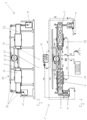
- the Fig. 1 and 2 show a pump device 1 according to the invention according to a first embodiment, in which the heat necessary to operate the pump device 1 is provided with the help of solar power.
- the pump device 1 has a first cylinder 2A and a second cylinder 2B, which are essentially aligned in the same way and arranged parallel to one another.
- a piston 3 is guided in each of the cylinders 2A, 2B and is connected to an associated piston rod 4.
- Each of the cylinders 2A, 2B has a front end 5 and a rear end 6, a working chamber 7 being formed between the piston 3 and the front end 5 and a pump chamber 8 being formed between the piston 3 and the rear end 6.
- a working fluid 9 is accommodated in the working chamber 7 of each cylinder 2A, 2B, which expands when heat is supplied, moves the respective piston 3 towards the rear end 6 and thus increases the volume of the working chamber 7.
- an inner shoulder 10 is formed in the cylinder 2A, 2B, against which the piston 3 rests in its end position - in which it cannot be pushed further towards the front end 5.
- the working chamber 7 of a cylinder 2A, 2B therefore has the smallest possible volume when the piston 3 is in the end position.
- Heat can be supplied to the working fluid 9 via a heating device 11 provided for this purpose in the area of the front end 5 of each cylinder 2A, 2B.
- the heating devices 11 have electrical heating elements, the heating coils 12 of which protrude into the working chambers 7.
- the heating devices 11 - and thus the heating coils 12 - are supplied with electrical current via power connections 13, so that the heating coils 12 through which the current flows supply heat to the working fluid 9.
- the power connections 13 are connected via power lines 14 to a solar panel 15, which generates solar power.
- the piston rods 4 of the cylinders 2A, 2B are coupled to one another via a pivotable linkage 16 in such a way that when one piston rod 4 is extended, the other piston rod 4 is automatically retracted and vice versa. Accordingly, the piston 3 of the first cylinder 2A also moves toward the front end 5 when the piston 3 of the second cylinder 2B is displaced toward the rear end 6 by the expanding working fluid 9 and vice versa.
- the pump chamber 8 of each cylinder 2A, 2B has two line connections 17.
- One of the line connections 17 is each connected via a supply line 18 to a liquid reservoir, in particular a water reservoir 19, of a pump liquid 20.
- the other line connection 17 is each connected via a discharge line 21 to a liquid distribution device, in particular a water distribution device 22, for distributing or dispensing the pump liquid 20.
- the line connection 17 connected to the supply line 18 has a check valve which prevents pump liquid 20 from flowing from the pump chamber 8 into the supply line 18.
- the line connection 17 connected to the drain line 21 has a check valve which prevents pump liquid 20 from being sucked out of the drain line 21 into the pump chamber 8.
- Each of the cylinders 2A, 2B is surrounded by a cooling device 23 which is spaced from the front end 5 of the cylinder 2A, 2B.
- the piston 3 must therefore first be moved a certain distance from the front end 5 to the rear end 6 of the cylinder 2A, 2B so that the working chamber 7 opens extends to the cooling device 23 and can be cooled by this.
- the cooling devices 23 are connected to the drain line 21 via a cooling line 24 or integrated directly into the drain line 21.
- An electrical control device 25 is coupled to the pistons 3 or piston rods 4, so that the power supply to the heating device 11 of each cylinder 2A, 2B is interrupted as soon as the piston 3 of this cylinder 2A, 2B is moved into the area of the rear end 6.
- the control device 25 can have sensors to measure how far the respective piston rod 4 has extended out of the cylinder 2A, 2B.
- a pumping process with the pumping device according to the invention proceeds, for example, as follows:
- the piston 3 of the first cylinder 2A is arranged in its end position at the front end 5 of the first cylinder 2A and rests on the inner shoulder 10.
- the working fluid 9 is in a liquid, substantially unexpanded state in which it does not exert pressure on the piston.
- Heat is supplied to the working fluid 9 of the first cylinder 2A via the heating device 11 of the first cylinder 2A, so that it at least partially evaporates and expands.
- the piston 3 of the first cylinder 2A is displaced towards the rear end 6 of the first cylinder 2A due to the excess pressure in the working chamber.
- the pump liquid 20 received in the pump chamber 8 is discharged from the pump chamber through the line connection 17 connected to the drain line 21 8 pressed out, and passed via the discharge line 21 and the cooling devices 23 to the water distribution device 22.
- the piston rod of the first cylinder 2A moves out of the first cylinder 2A, so that the control device 25 interrupts the power supply to the heating device 11 of the first cylinder 2A and thus also the heat supply to the working fluid 9 of the first cylinder 2A.
- the control device 25 restores the previously interrupted power supply to the heating device 11 of the second cylinder 2B.
- the 3 and 4 show the pump device 1 according to the invention according to a second embodiment, in which the heat necessary to operate the pump device 1 is generated with the help of solar rays 26.
- the pump devices 1 of the first and second embodiments are constructed essentially the same, but differ in the design of the heating device 11 and the control device 25.
- the heating devices 11 in the 3 and 4 Pump device 1 shown has lenses 27, with the help of which sun rays 26 can be bundled onto the front ends 5 of the cylinders 2A, 2B. At least one lens 27 is assigned to each cylinder 2A, 2B.
- the front end 5 of the cylinders 2A, 2B has a particularly high thermal conductivity, so that a large part of the heat generated by the bundling of the sun's rays 26 can be supplied to the working fluid 9 in the cylinders 2A, 2B.
- the control device 25 points in the 3 and 4 illustrated embodiment per cylinder 2A, 2B a control mechanism 28 coupled to the piston rods 4 and a pivotable shield 29.
- the respective Shield 29 is pivoted between the front end 5 of the cylinder 2A, 2B and the associated lens 27, so that no sun rays 26 can impinge on the front end 5 and heat it. The supply of heat to the working fluid 9 of the affected cylinder 2A, 2B is thus prevented.
- control mechanism 28 of each cylinder 2A, 2B comprises a linkage 28 coupled to the piston rods 4, which is moved in opposite directions to the piston rod 4 of the corresponding cylinder 2A, 2B with the aid of toothed rails 31 and a gear 32.
- the pump device 1 is shown as part of an irrigation device. However, it is also possible that the pump device 1 is part of another liquid system, for example a drinking water supply, an oil circuit, a bathing water circuit, etc.
- the 5 and 6 show the pump device 1 according to the invention according to a third embodiment.
- the cylinders 2A, 2B of the pump device 1 are aligned in a line and opposite to one another, so that the rear end 6 of each cylinder 2A, 2B points towards the rear end of the other cylinder 2B, 2A.
- the piston rods 4 of the pistons 3 guided in the cylinders 2A, 2B are connected to one another and form a single common piston rod 4.
- the control device 25 has a common control mechanism 28 coupled to the piston rod 4 and connected to the heating devices 11 of both cylinders 2A, 2B.
- the common control mechanism 28 of the cylinders 2A, 2B comprises a linkage 30 with chains coupled to the common piston rod 4, which is moved in opposite direction to the common piston rod 4 with the aid of toothed rails 31 and a gear 32.
- a pump device 1 in which the cylinders 2A, 2B as in the 5 and 6 illustrated embodiment are opposite and arranged in a line, an electrical control device 25, as in the Fig. 1 and 2 shown, have.
- the heating devices 11 are preferably permanently arranged at the front ends 5 of the cylinders 2A, 2B.
- the power supply to the heating devices 11 is interrupted or released by the electrical control device 25 - depending on the position of the common piston rod 4.
Landscapes
- Engineering & Computer Science (AREA)
- Chemical & Material Sciences (AREA)
- Combustion & Propulsion (AREA)
- Life Sciences & Earth Sciences (AREA)
- Sustainable Development (AREA)
- Sustainable Energy (AREA)
- Mechanical Engineering (AREA)
- General Engineering & Computer Science (AREA)
- Reciprocating Pumps (AREA)
Claims (15)
- Dispositif de pompage (1), en particulier pour pomper de l'eau, comprenant au moins un premier cylindre (2A) et un deuxième cylindre (2B), dans chacun desquels un piston (3) auquel est reliée une tige de piston (4) est guidé de manière coulissante, chacun des cylindres (2A, 2B) présentant une extrémité avant (5) et une extrémité arrière (6), les tiges de piston (4) sortant respectivement des cylindres (2A, 2B) à l'extrémité arrière (6) et étant couplées entre elles de telle sorte qu'un coulissement du piston (3) de l'un des cylindres (2A, 2B) vers l'extrémité arrière (6) de ce cylindre (2A, 2B) provoque un coulissement du piston (3) de l'autre cylindre (2B, 2A) vers son extrémité avant (5) et inversement, et au moins un raccord de conduite (17) menant dans chacun des cylindres (2A, 2B) chaque fois dans la zone de l'extrémité arrière (6), caractérisé en ce qu'un fluide de travail (9), auquel de la chaleur peut être amenée dans la zone de l'extrémité avant (5) par un moyen de chauffage (11), est contenu dans les cylindres (2A, 2B), chaque fois entre le piston (3) et l'extrémité avant (5), et en ce que l'amenée de la chaleur est commandée par un moyen de commande (25) de telle sorte que l'amenée de chaleur au fluide de travail (9) de l'un des cylindres (2A, 2B) est interrompue tandis que de la chaleur est amenée au fluide de travail (9) de l'autre cylindre (2B, 2A), et inversement.
- Dispositif de pompage selon la revendication 1, caractérisé en ce que le moyen de commande (25) est couplé aux pistons (3) ou aux tiges de piston (4) de telle sorte que, pour chacun des cylindres (2A, 2B), lorsque le piston (3) qui y est guidé coulisse vers l'extrémité arrière (6), l'amenée de chaleur au fluide de travail (9) de ce cylindre (2A, 2B) est interrompue et lorsque le piston (3) coulisse vers l'extrémité avant (5), l'amenée de chaleur est libérée.
- Dispositif de pompage selon la revendication 1 ou 2, caractérisé en ce que le moyen de chauffage (11) fournit la chaleur à l'aide d'énergie solaire.
- Dispositif de pompage selon l'une des revendications 1 à 3, caractérisé en ce que le moyen de chauffage (11) présente un élément chauffant fonctionnant électriquement disposé à l'extrémité avant (5) du cylindre respectif (2A, 2B), et en ce que l'alimentation en courant de l'élément chauffant peut être interrompue ou établie par le moyen de commande (25), en particulier en ce que l'élément chauffant présente une bobine chauffante (12) pouvant être chauffée à l'aide d'un courant électrique ou un élément oscillant pouvant être mis en oscillation à l'aide d'un courant électrique.
- Dispositif de pompage selon l'une des revendications 1 à 3, caractérisé en ce que le moyen de chauffage (11) présente un élément chauffant mobile qui peut être disposé à l'extrémité avant (5) par le moyen de commande (25), de sorte que la chaleur provenant de l'élément chauffant peut être amenée au fluide de travail (9) par l'extrémité avant (5), ou que l'amenée de chaleur peut être interrompue en enlevant l'élément chauffant, ou en ce que le moyen de chauffage (11) présente au moins un élément collecteur, par exemple un miroir concave ou une lentille (27), au moyen duquel des rayons solaires (26) peuvent être amenés à l'extrémité avant (5), de sorte que l'extrémité avant (5) se réchauffe et cède de la chaleur au fluide de travail (9), et que l'amenée de rayons solaires (26) peut être interrompue par le moyen de commande (25), en particulier en plaçant un écran (29) entre l'extrémité avant (5) et l'élément collecteur.
- Dispositif de pompage selon l'une des revendications 1 à 5, caractérisé en ce que le moyen de commande (25) est couplé mécaniquement, en particulier par une tringlerie (39) et/ou des roues dentées (32) et/ou des courroies et/ou un câble, ou électriquement ou électroniquement aux pistons (3) ou aux tiges de piston (4).
- Dispositif de pompage selon l'une des revendications 1 à 6, caractérisé en ce qu'à distance de l'extrémité avant (5), sur ou autour de chacun des cylindres (2A, 2B), est disposé un moyen de refroidissement (23) permettant de retirer de la chaleur au fluide de travail (9).
- Dispositif de pompage selon l'une des revendications 1 à 7, caractérisé en ce que le fluide de travail (9) est au moins partiellement gazeux lorsque de la chaleur lui est amenée et au moins partiellement liquide lorsque de la chaleur en est retirée, ou en ce que le fluide de travail (9) est sensiblement gazeux lorsque de la chaleur lui est amenée et en est retirée, ou en ce que le fluide de travail (9) est sensiblement liquide lorsque de la chaleur lui est amenée et en est retirée.
- Dispositif de pompage selon l'une des revendications 1 à 8, caractérisé en ce que dans chacun des cylindres (2A, 2B), il règne une dépression entre le piston (3) et l'extrémité avant (5) lorsque le piston (3) du cylindre respectif (2A, 2B) est disposé dans une position extrême dans la zone de l'extrémité avant (5) et que le fluide de travail (9) est dans un état non dilaté.
- Dispositif de pompage selon l'une des revendications 1 à 9, caractérisé en ce que les cylindres (2A, 2B) sont orientés dans le même sens, en particulier disposés côte à côte, ou orientés en sens inverse, en particulier disposés en ligne.
- Dispositif de pompage selon l'une des revendications 1 à 10, caractérisé en ce que les tiges de piston (4) sont couplées entre elles par une tringlerie mobile (16) et/ou des roues dentées et/ou des courroies et/ou un câble, ou en ce que les tiges de piston (4) sont couplées directement entre elles par un accouplement sensiblement rigide ou une tringlerie rigide, ou en ce que les tiges de piston (4) sont chacune un tronçon d'une seule tige de piston (4).
- Dispositif de pompage selon l'une des revendications 1 à 11, caractérisé en ce qu'il existe un seul raccord de conduite (17) par cylindre (2A, 2B), auquel est raccordée une conduite intermédiaire qui peut être reliée à une conduite d'alimentation (18) par laquelle un liquide à pomper (20) peut être aspiré, et à une conduite d'évacuation (21), par laquelle le liquide à pomper (29) peut être évacué, ou en ce qu'il existe au moins deux raccords de conduite (17), l'un des raccords de conduite (17) pouvant être relié à une conduite d'alimentation (18) par laquelle un liquide à pomper (20) peut être aspiré, et l'autre des raccords de conduite (17) pouvant être relié à une conduite d'évacuation (21) par laquelle le liquide à pomper (20) peut être évacué.
- Dispositif de pompage selon l'une des revendications 1 à 12, caractérisé en ce qu'un clapet anti-retour bloque la conduite d'alimentation (18) lors du coulissement du piston (3) vers l'extrémité arrière (6), et en ce qu'un autre clapet anti-retour bloque la conduite d'évacuation (21) lors du coulissement du piston (3) vers l'extrémité avant (5).
- Dispositif de pompage selon l'une des revendications 1 à 13, caractérisé en ce que les tiges de piston (4) sont reliées mécaniquement à au moins un autre moyen, par exemple une pompe à tiges ou un générateur, de telle sorte que cet autre moyen peut être entraîné ou actionné par le mouvement des tiges de piston (4).
- Dispositif d'irrigation, qui présente au moins un dispositif de pompage (1), au moins une conduite d'alimentation (18) par laquelle le(s) dispositif(s) de pompage (1) peut/peuvent être relié(s) à un réservoir d'eau (19), au moins un moyen de distribution d'eau (22) et au moins une conduite d'évacuation (21) par laquelle le(s) dispositif(s) de pompage (1) est/sont relié(s) au(x) moyen(s) de distribution d'eau (22) et qui présente de préférence au moins un panneau solaire (15) pour produire du courant électrique, caractérisé en ce que le(s) dispositif(s) de pompage (1) est/sont réalisé(s) selon l'une des revendications 1 à 14.
Applications Claiming Priority (3)
| Application Number | Priority Date | Filing Date | Title |
|---|---|---|---|
| AT2512019 | 2019-07-08 | ||
| ATA288/2019A AT522820B1 (de) | 2019-07-08 | 2019-09-05 | Pumpvorrichtung |
| PCT/EP2020/068477 WO2021004846A1 (fr) | 2019-07-08 | 2020-07-01 | Système de pompe |
Publications (3)
| Publication Number | Publication Date |
|---|---|
| EP3997337A1 EP3997337A1 (fr) | 2022-05-18 |
| EP3997337B1 true EP3997337B1 (fr) | 2024-03-13 |
| EP3997337C0 EP3997337C0 (fr) | 2024-03-13 |
Family
ID=71465312
Family Applications (1)
| Application Number | Title | Priority Date | Filing Date |
|---|---|---|---|
| EP20736625.3A Active EP3997337B1 (fr) | 2019-07-08 | 2020-07-01 | Dispositif de pompe |
Country Status (2)
| Country | Link |
|---|---|
| EP (1) | EP3997337B1 (fr) |
| WO (1) | WO2021004846A1 (fr) |
Family Cites Families (5)
| Publication number | Priority date | Publication date | Assignee | Title |
|---|---|---|---|---|
| US308509A (en) * | 1884-11-25 | moleod | ||
| FR32458E (fr) * | 1926-10-18 | 1928-01-24 | Pompe aspirante et foulante actionnée à distance par un fluide sous pression convenable et constante | |
| US4150923A (en) * | 1978-04-20 | 1979-04-24 | Wardman John C | Reciprocating pump powered by solar and wind energy |
| WO2014171934A1 (fr) * | 2013-04-17 | 2014-10-23 | International Truck Intellectual Property Company, Llc | Pompe à fonctionnement thermique |
| CN203272045U (zh) * | 2013-05-06 | 2013-11-06 | 肖怀东 | 推挽式太阳能水泵 |
-
2020
- 2020-07-01 WO PCT/EP2020/068477 patent/WO2021004846A1/fr not_active Ceased
- 2020-07-01 EP EP20736625.3A patent/EP3997337B1/fr active Active
Also Published As
| Publication number | Publication date |
|---|---|
| WO2021004846A1 (fr) | 2021-01-14 |
| EP3997337A1 (fr) | 2022-05-18 |
| EP3997337C0 (fr) | 2024-03-13 |
Similar Documents
| Publication | Publication Date | Title |
|---|---|---|
| DE2933213A1 (de) | Verfahren und vorrichtung zur umwandlung von waermeenergie in mechanische arbeit | |
| DE2232993A1 (de) | Schneidvorrichtung zum schneiden insbesondere von gestein mittels eines fluessigkeitsstrahls | |
| EP3997337B1 (fr) | Dispositif de pompe | |
| DE2744952C2 (de) | Solare Pumpanlage zum Pumpen von Flüssigkeiten | |
| DE2507330B2 (de) | Verfahren und Vorrichtung zur Umwandlung der Energie der Meereswellenbewegung in Nutzenergie | |
| AT522820B1 (de) | Pumpvorrichtung | |
| DE10231008A1 (de) | Drehbar gelagerte Hydro-Kompressorpumpe | |
| DE102019006695A1 (de) | Hydraulische Kolbeneinrichtung, welche mindestens zum Zwecke einer Gasverdichtung verwendbar ist, Druckgasenergiewandlungseinrichtung, Druckgasenergiewandlungs-Wärmetauscher-Einrichtung, Druckgasenergiewandlungs-Wärmetauscher-Einrichtungs-Vorstufeneinrichtung und Druckgasenergiewandlungsvorrichtung | |
| DE102019002370A1 (de) | Hydraulische Kolbeneinrichtung, welche mindestens zum Zwecke einer Gasverdichtung verwendbar ist, Druckgasenergiewandlungseinrichtung, Druckgasenenergiewandlungs-Wärmetauscher-Einrichtung, Druckgasenergiewandlungs-Wärmetauscher-Einrichtungs-Vorstufeneinrichtung und Druckgasenenergiewandlungsvorrichtung | |
| DE102010061846A1 (de) | Geothermieanlage und Verfahren zur Energiegewinnung aus Erdwärme | |
| DE3428653A1 (de) | Quergestroemter co(pfeil abwaerts)2(pfeil abwaerts)-laser | |
| DE102013201582B4 (de) | Verfahren zur Herstellung einer Kühlvorrichtung für eine Batterieeinheit, Kühlvorrichtung für eine Batterieeinheit sowie Batterieeinheit | |
| DE2636004A1 (de) | Verfahren zur umwandlung der waermeenergie einer fluessigkeit in mechanische energie und vorrichtung zur durchfuehrung dieses verfahrens | |
| DE2756093A1 (de) | Waermekraftmaschine | |
| DE102013113252B4 (de) | Einrichtung mit wenigstens einer Kraft- und/oder Arbeitsmaschine, Pumpspeicherkraftwerk, industrielle Anlage und Verfahren zu deren Betrieb | |
| DE102018201619B4 (de) | Wärmespeichervorrichtung, Arbeitsvorrichtung, Verfahren zum Betreiben einer Wärmespeichervorrichtung und Verfahren zum Betreiben einer Arbeitsvorrichtung | |
| EP2141420A2 (fr) | Dispositif de chauffage et/ou de refroidissement de bâtiment | |
| DE102004032615A1 (de) | Vorrichtung und Verfahren zur Energieerzeugung mittels Schwerkraft, Strömung und Auftriebskraft | |
| AT527260A1 (de) | Vorrichtung mit einer Wärmekraftmaschine und einer damit antreibbaren Pumpe | |
| DE8809188U1 (de) | Antriebsvorrichtung für taktweise arbeitende Schneidvorrichtungen | |
| DE2919263A1 (de) | Waermekraftmaschine | |
| DE2828491C2 (fr) | ||
| DE102011015371A1 (de) | Energiespeichervorrichtung mit Metallschaum im Arbeitsraum | |
| DE3005767A1 (de) | Verfahren und vorrichtung zur hydrostatisch-pneumatischen energiegewinnung | |
| DE2720021C2 (de) | Pumpanlage zum Kühlen von einem oder mehreren elektrischen Energiekabeln |
Legal Events
| Date | Code | Title | Description |
|---|---|---|---|
| STAA | Information on the status of an ep patent application or granted ep patent |
Free format text: STATUS: UNKNOWN |
|
| STAA | Information on the status of an ep patent application or granted ep patent |
Free format text: STATUS: THE INTERNATIONAL PUBLICATION HAS BEEN MADE |
|
| PUAI | Public reference made under article 153(3) epc to a published international application that has entered the european phase |
Free format text: ORIGINAL CODE: 0009012 |
|
| STAA | Information on the status of an ep patent application or granted ep patent |
Free format text: STATUS: REQUEST FOR EXAMINATION WAS MADE |
|
| 17P | Request for examination filed |
Effective date: 20220202 |
|
| AK | Designated contracting states |
Kind code of ref document: A1 Designated state(s): AL AT BE BG CH CY CZ DE DK EE ES FI FR GB GR HR HU IE IS IT LI LT LU LV MC MK MT NL NO PL PT RO RS SE SI SK SM TR |
|
| DAX | Request for extension of the european patent (deleted) | ||
| RAV | Requested validation state of the european patent: fee paid |
Extension state: TN Effective date: 20220202 Extension state: MA Effective date: 20220202 |
|
| GRAP | Despatch of communication of intention to grant a patent |
Free format text: ORIGINAL CODE: EPIDOSNIGR1 |
|
| RIC1 | Information provided on ipc code assigned before grant |
Ipc: F03G 6/06 20060101ALI20221018BHEP Ipc: F04B 17/00 20060101ALI20221018BHEP Ipc: F04B 1/02 20060101ALI20221018BHEP Ipc: F04B 9/135 20060101AFI20221018BHEP |
|
| STAA | Information on the status of an ep patent application or granted ep patent |
Free format text: STATUS: GRANT OF PATENT IS INTENDED |
|
| INTG | Intention to grant announced |
Effective date: 20221124 |
|
| GRAJ | Information related to disapproval of communication of intention to grant by the applicant or resumption of examination proceedings by the epo deleted |
Free format text: ORIGINAL CODE: EPIDOSDIGR1 |
|
| STAA | Information on the status of an ep patent application or granted ep patent |
Free format text: STATUS: REQUEST FOR EXAMINATION WAS MADE |
|
| GRAP | Despatch of communication of intention to grant a patent |
Free format text: ORIGINAL CODE: EPIDOSNIGR1 |
|
| STAA | Information on the status of an ep patent application or granted ep patent |
Free format text: STATUS: GRANT OF PATENT IS INTENDED |
|
| INTC | Intention to grant announced (deleted) | ||
| INTG | Intention to grant announced |
Effective date: 20230426 |
|
| GRAF | Information related to payment of grant fee modified |
Free format text: ORIGINAL CODE: EPIDOSCIGR3 |
|
| GRAS | Grant fee paid |
Free format text: ORIGINAL CODE: EPIDOSNIGR3 |
|
| GRAA | (expected) grant |
Free format text: ORIGINAL CODE: 0009210 |
|
| STAA | Information on the status of an ep patent application or granted ep patent |
Free format text: STATUS: THE PATENT HAS BEEN GRANTED |
|
| AK | Designated contracting states |
Kind code of ref document: B1 Designated state(s): AL AT BE BG CH CY CZ DE DK EE ES FI FR GB GR HR HU IE IS IT LI LT LU LV MC MK MT NL NO PL PT RO RS SE SI SK SM TR |
|
| REG | Reference to a national code |
Ref country code: GB Ref legal event code: FG4D Free format text: NOT ENGLISH |
|
| REG | Reference to a national code |
Ref country code: CH Ref legal event code: EP |
|
| REG | Reference to a national code |
Ref country code: DE Ref legal event code: R096 Ref document number: 502020007352 Country of ref document: DE |
|
| REG | Reference to a national code |
Ref country code: IE Ref legal event code: FG4D Free format text: LANGUAGE OF EP DOCUMENT: GERMAN |
|
| U01 | Request for unitary effect filed |
Effective date: 20240412 |
|
| U07 | Unitary effect registered |
Designated state(s): AT BE BG DE DK EE FI FR IT LT LU LV MT NL PT SE SI Effective date: 20240418 |
|
| PG25 | Lapsed in a contracting state [announced via postgrant information from national office to epo] |
Ref country code: GR Free format text: LAPSE BECAUSE OF FAILURE TO SUBMIT A TRANSLATION OF THE DESCRIPTION OR TO PAY THE FEE WITHIN THE PRESCRIBED TIME-LIMIT Effective date: 20240614 |
|
| PG25 | Lapsed in a contracting state [announced via postgrant information from national office to epo] |
Ref country code: RS Free format text: LAPSE BECAUSE OF FAILURE TO SUBMIT A TRANSLATION OF THE DESCRIPTION OR TO PAY THE FEE WITHIN THE PRESCRIBED TIME-LIMIT Effective date: 20240613 Ref country code: HR Free format text: LAPSE BECAUSE OF FAILURE TO SUBMIT A TRANSLATION OF THE DESCRIPTION OR TO PAY THE FEE WITHIN THE PRESCRIBED TIME-LIMIT Effective date: 20240313 |
|
| PG25 | Lapsed in a contracting state [announced via postgrant information from national office to epo] |
Ref country code: ES Free format text: LAPSE BECAUSE OF FAILURE TO SUBMIT A TRANSLATION OF THE DESCRIPTION OR TO PAY THE FEE WITHIN THE PRESCRIBED TIME-LIMIT Effective date: 20240313 |
|
| PG25 | Lapsed in a contracting state [announced via postgrant information from national office to epo] |
Ref country code: RS Free format text: LAPSE BECAUSE OF FAILURE TO SUBMIT A TRANSLATION OF THE DESCRIPTION OR TO PAY THE FEE WITHIN THE PRESCRIBED TIME-LIMIT Effective date: 20240613 Ref country code: NO Free format text: LAPSE BECAUSE OF FAILURE TO SUBMIT A TRANSLATION OF THE DESCRIPTION OR TO PAY THE FEE WITHIN THE PRESCRIBED TIME-LIMIT Effective date: 20240613 Ref country code: HR Free format text: LAPSE BECAUSE OF FAILURE TO SUBMIT A TRANSLATION OF THE DESCRIPTION OR TO PAY THE FEE WITHIN THE PRESCRIBED TIME-LIMIT Effective date: 20240313 Ref country code: GR Free format text: LAPSE BECAUSE OF FAILURE TO SUBMIT A TRANSLATION OF THE DESCRIPTION OR TO PAY THE FEE WITHIN THE PRESCRIBED TIME-LIMIT Effective date: 20240614 Ref country code: ES Free format text: LAPSE BECAUSE OF FAILURE TO SUBMIT A TRANSLATION OF THE DESCRIPTION OR TO PAY THE FEE WITHIN THE PRESCRIBED TIME-LIMIT Effective date: 20240313 |
|
| U20 | Renewal fee for the european patent with unitary effect paid |
Year of fee payment: 5 Effective date: 20240726 |
|
| PG25 | Lapsed in a contracting state [announced via postgrant information from national office to epo] |
Ref country code: IS Free format text: LAPSE BECAUSE OF FAILURE TO SUBMIT A TRANSLATION OF THE DESCRIPTION OR TO PAY THE FEE WITHIN THE PRESCRIBED TIME-LIMIT Effective date: 20240713 |
|
| PG25 | Lapsed in a contracting state [announced via postgrant information from national office to epo] |
Ref country code: SM Free format text: LAPSE BECAUSE OF FAILURE TO SUBMIT A TRANSLATION OF THE DESCRIPTION OR TO PAY THE FEE WITHIN THE PRESCRIBED TIME-LIMIT Effective date: 20240313 |
|
| PG25 | Lapsed in a contracting state [announced via postgrant information from national office to epo] |
Ref country code: CZ Free format text: LAPSE BECAUSE OF FAILURE TO SUBMIT A TRANSLATION OF THE DESCRIPTION OR TO PAY THE FEE WITHIN THE PRESCRIBED TIME-LIMIT Effective date: 20240313 |
|
| PG25 | Lapsed in a contracting state [announced via postgrant information from national office to epo] |
Ref country code: PL Free format text: LAPSE BECAUSE OF FAILURE TO SUBMIT A TRANSLATION OF THE DESCRIPTION OR TO PAY THE FEE WITHIN THE PRESCRIBED TIME-LIMIT Effective date: 20240313 |
|
| PG25 | Lapsed in a contracting state [announced via postgrant information from national office to epo] |
Ref country code: SK Free format text: LAPSE BECAUSE OF FAILURE TO SUBMIT A TRANSLATION OF THE DESCRIPTION OR TO PAY THE FEE WITHIN THE PRESCRIBED TIME-LIMIT Effective date: 20240313 |
|
| PG25 | Lapsed in a contracting state [announced via postgrant information from national office to epo] |
Ref country code: SM Free format text: LAPSE BECAUSE OF FAILURE TO SUBMIT A TRANSLATION OF THE DESCRIPTION OR TO PAY THE FEE WITHIN THE PRESCRIBED TIME-LIMIT Effective date: 20240313 Ref country code: SK Free format text: LAPSE BECAUSE OF FAILURE TO SUBMIT A TRANSLATION OF THE DESCRIPTION OR TO PAY THE FEE WITHIN THE PRESCRIBED TIME-LIMIT Effective date: 20240313 Ref country code: RO Free format text: LAPSE BECAUSE OF FAILURE TO SUBMIT A TRANSLATION OF THE DESCRIPTION OR TO PAY THE FEE WITHIN THE PRESCRIBED TIME-LIMIT Effective date: 20240313 Ref country code: PL Free format text: LAPSE BECAUSE OF FAILURE TO SUBMIT A TRANSLATION OF THE DESCRIPTION OR TO PAY THE FEE WITHIN THE PRESCRIBED TIME-LIMIT Effective date: 20240313 Ref country code: IS Free format text: LAPSE BECAUSE OF FAILURE TO SUBMIT A TRANSLATION OF THE DESCRIPTION OR TO PAY THE FEE WITHIN THE PRESCRIBED TIME-LIMIT Effective date: 20240713 Ref country code: CZ Free format text: LAPSE BECAUSE OF FAILURE TO SUBMIT A TRANSLATION OF THE DESCRIPTION OR TO PAY THE FEE WITHIN THE PRESCRIBED TIME-LIMIT Effective date: 20240313 |
|
| REG | Reference to a national code |
Ref country code: DE Ref legal event code: R097 Ref document number: 502020007352 Country of ref document: DE |
|
| PLBE | No opposition filed within time limit |
Free format text: ORIGINAL CODE: 0009261 |
|
| STAA | Information on the status of an ep patent application or granted ep patent |
Free format text: STATUS: NO OPPOSITION FILED WITHIN TIME LIMIT |
|
| PG25 | Lapsed in a contracting state [announced via postgrant information from national office to epo] |
Ref country code: MC Free format text: LAPSE BECAUSE OF FAILURE TO SUBMIT A TRANSLATION OF THE DESCRIPTION OR TO PAY THE FEE WITHIN THE PRESCRIBED TIME-LIMIT Effective date: 20240313 |
|
| 26N | No opposition filed |
Effective date: 20241216 |
|
| REG | Reference to a national code |
Ref country code: CH Ref legal event code: PL |
|
| GBPC | Gb: european patent ceased through non-payment of renewal fee |
Effective date: 20240701 |
|
| PG25 | Lapsed in a contracting state [announced via postgrant information from national office to epo] |
Ref country code: CH Free format text: LAPSE BECAUSE OF NON-PAYMENT OF DUE FEES Effective date: 20240731 |
|
| PG25 | Lapsed in a contracting state [announced via postgrant information from national office to epo] |
Ref country code: GB Free format text: LAPSE BECAUSE OF NON-PAYMENT OF DUE FEES Effective date: 20240701 |
|
| PG25 | Lapsed in a contracting state [announced via postgrant information from national office to epo] |
Ref country code: IE Free format text: LAPSE BECAUSE OF NON-PAYMENT OF DUE FEES Effective date: 20240701 |
|
| VS25 | Lapsed in a validation state [announced via postgrant information from nat. office to epo] |
Ref country code: MA Free format text: FAILURE TO ELECT DOMICILE IN THE NATIONAL COUNTRY Effective date: 20240614 |
|
| PG25 | Lapsed in a contracting state [announced via postgrant information from national office to epo] |
Ref country code: CY Free format text: LAPSE BECAUSE OF FAILURE TO SUBMIT A TRANSLATION OF THE DESCRIPTION OR TO PAY THE FEE WITHIN THE PRESCRIBED TIME-LIMIT; INVALID AB INITIO Effective date: 20200701 |
|
| U21 | Renewal fee for the european patent with unitary effect paid with additional fee |
Year of fee payment: 6 Effective date: 20260129 |
|
| PG25 | Lapsed in a contracting state [announced via postgrant information from national office to epo] |
Ref country code: HU Free format text: LAPSE BECAUSE OF FAILURE TO SUBMIT A TRANSLATION OF THE DESCRIPTION OR TO PAY THE FEE WITHIN THE PRESCRIBED TIME-LIMIT; INVALID AB INITIO Effective date: 20200701 |