EP3997400B1 - Corps adiabatique sous vide et réfrigérateur - Google Patents
Corps adiabatique sous vide et réfrigérateur Download PDFInfo
- Publication number
- EP3997400B1 EP3997400B1 EP20836297.0A EP20836297A EP3997400B1 EP 3997400 B1 EP3997400 B1 EP 3997400B1 EP 20836297 A EP20836297 A EP 20836297A EP 3997400 B1 EP3997400 B1 EP 3997400B1
- Authority
- EP
- European Patent Office
- Prior art keywords
- space
- cool air
- vacuum
- plate
- refrigerator
- Prior art date
- Legal status (The legal status is an assumption and is not a legal conclusion. Google has not performed a legal analysis and makes no representation as to the accuracy of the status listed.)
- Active
Links
Images














Classifications
-
- F—MECHANICAL ENGINEERING; LIGHTING; HEATING; WEAPONS; BLASTING
- F25—REFRIGERATION OR COOLING; COMBINED HEATING AND REFRIGERATION SYSTEMS; HEAT PUMP SYSTEMS; MANUFACTURE OR STORAGE OF ICE; LIQUEFACTION SOLIDIFICATION OF GASES
- F25D—REFRIGERATORS; COLD ROOMS; ICE-BOXES; COOLING OR FREEZING APPARATUS NOT OTHERWISE PROVIDED FOR
- F25D23/00—General constructional features
- F25D23/06—Walls
- F25D23/062—Walls defining a cabinet
- F25D23/063—Walls defining a cabinet formed by an assembly of panels
-
- F—MECHANICAL ENGINEERING; LIGHTING; HEATING; WEAPONS; BLASTING
- F16—ENGINEERING ELEMENTS AND UNITS; GENERAL MEASURES FOR PRODUCING AND MAINTAINING EFFECTIVE FUNCTIONING OF MACHINES OR INSTALLATIONS; THERMAL INSULATION IN GENERAL
- F16L—PIPES; JOINTS OR FITTINGS FOR PIPES; SUPPORTS FOR PIPES, CABLES OR PROTECTIVE TUBING; MEANS FOR THERMAL INSULATION IN GENERAL
- F16L59/00—Thermal insulation in general
- F16L59/06—Arrangements using an air layer or vacuum
- F16L59/065—Arrangements using an air layer or vacuum using vacuum
-
- F—MECHANICAL ENGINEERING; LIGHTING; HEATING; WEAPONS; BLASTING
- F25—REFRIGERATION OR COOLING; COMBINED HEATING AND REFRIGERATION SYSTEMS; HEAT PUMP SYSTEMS; MANUFACTURE OR STORAGE OF ICE; LIQUEFACTION SOLIDIFICATION OF GASES
- F25D—REFRIGERATORS; COLD ROOMS; ICE-BOXES; COOLING OR FREEZING APPARATUS NOT OTHERWISE PROVIDED FOR
- F25D11/00—Self-contained movable devices, e.g. domestic refrigerators
- F25D11/02—Self-contained movable devices, e.g. domestic refrigerators with cooling compartments at different temperatures
- F25D11/022—Self-contained movable devices, e.g. domestic refrigerators with cooling compartments at different temperatures with two or more evaporators
-
- F—MECHANICAL ENGINEERING; LIGHTING; HEATING; WEAPONS; BLASTING
- F25—REFRIGERATION OR COOLING; COMBINED HEATING AND REFRIGERATION SYSTEMS; HEAT PUMP SYSTEMS; MANUFACTURE OR STORAGE OF ICE; LIQUEFACTION SOLIDIFICATION OF GASES
- F25D—REFRIGERATORS; COLD ROOMS; ICE-BOXES; COOLING OR FREEZING APPARATUS NOT OTHERWISE PROVIDED FOR
- F25D17/00—Arrangements for circulating cooling fluids; Arrangements for circulating gas, e.g. air, within refrigerated spaces
- F25D17/04—Arrangements for circulating cooling fluids; Arrangements for circulating gas, e.g. air, within refrigerated spaces for circulating air, e.g. by convection
- F25D17/06—Arrangements for circulating cooling fluids; Arrangements for circulating gas, e.g. air, within refrigerated spaces for circulating air, e.g. by convection by forced circulation
- F25D17/062—Arrangements for circulating cooling fluids; Arrangements for circulating gas, e.g. air, within refrigerated spaces for circulating air, e.g. by convection by forced circulation in household refrigerators
- F25D17/065—Arrangements for circulating cooling fluids; Arrangements for circulating gas, e.g. air, within refrigerated spaces for circulating air, e.g. by convection by forced circulation in household refrigerators with compartments at different temperatures
-
- F—MECHANICAL ENGINEERING; LIGHTING; HEATING; WEAPONS; BLASTING
- F25—REFRIGERATION OR COOLING; COMBINED HEATING AND REFRIGERATION SYSTEMS; HEAT PUMP SYSTEMS; MANUFACTURE OR STORAGE OF ICE; LIQUEFACTION SOLIDIFICATION OF GASES
- F25D—REFRIGERATORS; COLD ROOMS; ICE-BOXES; COOLING OR FREEZING APPARATUS NOT OTHERWISE PROVIDED FOR
- F25D23/00—General constructional features
- F25D23/006—General constructional features for mounting refrigerating machinery components
-
- F—MECHANICAL ENGINEERING; LIGHTING; HEATING; WEAPONS; BLASTING
- F25—REFRIGERATION OR COOLING; COMBINED HEATING AND REFRIGERATION SYSTEMS; HEAT PUMP SYSTEMS; MANUFACTURE OR STORAGE OF ICE; LIQUEFACTION SOLIDIFICATION OF GASES
- F25D—REFRIGERATORS; COLD ROOMS; ICE-BOXES; COOLING OR FREEZING APPARATUS NOT OTHERWISE PROVIDED FOR
- F25D23/00—General constructional features
- F25D23/02—Doors; Covers
- F25D23/028—Details
-
- F—MECHANICAL ENGINEERING; LIGHTING; HEATING; WEAPONS; BLASTING
- F25—REFRIGERATION OR COOLING; COMBINED HEATING AND REFRIGERATION SYSTEMS; HEAT PUMP SYSTEMS; MANUFACTURE OR STORAGE OF ICE; LIQUEFACTION SOLIDIFICATION OF GASES
- F25D—REFRIGERATORS; COLD ROOMS; ICE-BOXES; COOLING OR FREEZING APPARATUS NOT OTHERWISE PROVIDED FOR
- F25D23/00—General constructional features
- F25D23/06—Walls
- F25D23/061—Walls with conduit means
-
- F—MECHANICAL ENGINEERING; LIGHTING; HEATING; WEAPONS; BLASTING
- F25—REFRIGERATION OR COOLING; COMBINED HEATING AND REFRIGERATION SYSTEMS; HEAT PUMP SYSTEMS; MANUFACTURE OR STORAGE OF ICE; LIQUEFACTION SOLIDIFICATION OF GASES
- F25D—REFRIGERATORS; COLD ROOMS; ICE-BOXES; COOLING OR FREEZING APPARATUS NOT OTHERWISE PROVIDED FOR
- F25D23/00—General constructional features
- F25D23/06—Walls
- F25D23/065—Details
-
- F—MECHANICAL ENGINEERING; LIGHTING; HEATING; WEAPONS; BLASTING
- F25—REFRIGERATION OR COOLING; COMBINED HEATING AND REFRIGERATION SYSTEMS; HEAT PUMP SYSTEMS; MANUFACTURE OR STORAGE OF ICE; LIQUEFACTION SOLIDIFICATION OF GASES
- F25D—REFRIGERATORS; COLD ROOMS; ICE-BOXES; COOLING OR FREEZING APPARATUS NOT OTHERWISE PROVIDED FOR
- F25D23/00—General constructional features
- F25D23/06—Walls
- F25D23/065—Details
- F25D23/068—Arrangements for circulating fluids through the insulating material
-
- F—MECHANICAL ENGINEERING; LIGHTING; HEATING; WEAPONS; BLASTING
- F25—REFRIGERATION OR COOLING; COMBINED HEATING AND REFRIGERATION SYSTEMS; HEAT PUMP SYSTEMS; MANUFACTURE OR STORAGE OF ICE; LIQUEFACTION SOLIDIFICATION OF GASES
- F25D—REFRIGERATORS; COLD ROOMS; ICE-BOXES; COOLING OR FREEZING APPARATUS NOT OTHERWISE PROVIDED FOR
- F25D23/00—General constructional features
- F25D23/06—Walls
- F25D23/069—Cooling space dividing partitions
-
- F—MECHANICAL ENGINEERING; LIGHTING; HEATING; WEAPONS; BLASTING
- F25—REFRIGERATION OR COOLING; COMBINED HEATING AND REFRIGERATION SYSTEMS; HEAT PUMP SYSTEMS; MANUFACTURE OR STORAGE OF ICE; LIQUEFACTION SOLIDIFICATION OF GASES
- F25D—REFRIGERATORS; COLD ROOMS; ICE-BOXES; COOLING OR FREEZING APPARATUS NOT OTHERWISE PROVIDED FOR
- F25D21/00—Defrosting; Preventing frosting; Removing condensed or defrost water
- F25D21/14—Collecting or removing condensed and defrost water; Drip trays
-
- F—MECHANICAL ENGINEERING; LIGHTING; HEATING; WEAPONS; BLASTING
- F25—REFRIGERATION OR COOLING; COMBINED HEATING AND REFRIGERATION SYSTEMS; HEAT PUMP SYSTEMS; MANUFACTURE OR STORAGE OF ICE; LIQUEFACTION SOLIDIFICATION OF GASES
- F25D—REFRIGERATORS; COLD ROOMS; ICE-BOXES; COOLING OR FREEZING APPARATUS NOT OTHERWISE PROVIDED FOR
- F25D2201/00—Insulation
- F25D2201/10—Insulation with respect to heat
- F25D2201/14—Insulation with respect to heat using subatmospheric pressure
-
- F—MECHANICAL ENGINEERING; LIGHTING; HEATING; WEAPONS; BLASTING
- F25—REFRIGERATION OR COOLING; COMBINED HEATING AND REFRIGERATION SYSTEMS; HEAT PUMP SYSTEMS; MANUFACTURE OR STORAGE OF ICE; LIQUEFACTION SOLIDIFICATION OF GASES
- F25D—REFRIGERATORS; COLD ROOMS; ICE-BOXES; COOLING OR FREEZING APPARATUS NOT OTHERWISE PROVIDED FOR
- F25D2317/00—Details or arrangements for circulating cooling fluids; Details or arrangements for circulating gas, e.g. air, within refrigerated spaces, not provided for in other groups of this subclass
- F25D2317/06—Details or arrangements for circulating cooling fluids; Details or arrangements for circulating gas, e.g. air, within refrigerated spaces, not provided for in other groups of this subclass with forced air circulation
- F25D2317/065—Details or arrangements for circulating cooling fluids; Details or arrangements for circulating gas, e.g. air, within refrigerated spaces, not provided for in other groups of this subclass with forced air circulation characterised by the air return
- F25D2317/0652—Details or arrangements for circulating cooling fluids; Details or arrangements for circulating gas, e.g. air, within refrigerated spaces, not provided for in other groups of this subclass with forced air circulation characterised by the air return through the corner
-
- F—MECHANICAL ENGINEERING; LIGHTING; HEATING; WEAPONS; BLASTING
- F25—REFRIGERATION OR COOLING; COMBINED HEATING AND REFRIGERATION SYSTEMS; HEAT PUMP SYSTEMS; MANUFACTURE OR STORAGE OF ICE; LIQUEFACTION SOLIDIFICATION OF GASES
- F25D—REFRIGERATORS; COLD ROOMS; ICE-BOXES; COOLING OR FREEZING APPARATUS NOT OTHERWISE PROVIDED FOR
- F25D2317/00—Details or arrangements for circulating cooling fluids; Details or arrangements for circulating gas, e.g. air, within refrigerated spaces, not provided for in other groups of this subclass
- F25D2317/06—Details or arrangements for circulating cooling fluids; Details or arrangements for circulating gas, e.g. air, within refrigerated spaces, not provided for in other groups of this subclass with forced air circulation
- F25D2317/065—Details or arrangements for circulating cooling fluids; Details or arrangements for circulating gas, e.g. air, within refrigerated spaces, not provided for in other groups of this subclass with forced air circulation characterised by the air return
- F25D2317/0654—Details or arrangements for circulating cooling fluids; Details or arrangements for circulating gas, e.g. air, within refrigerated spaces, not provided for in other groups of this subclass with forced air circulation characterised by the air return through the side
-
- F—MECHANICAL ENGINEERING; LIGHTING; HEATING; WEAPONS; BLASTING
- F25—REFRIGERATION OR COOLING; COMBINED HEATING AND REFRIGERATION SYSTEMS; HEAT PUMP SYSTEMS; MANUFACTURE OR STORAGE OF ICE; LIQUEFACTION SOLIDIFICATION OF GASES
- F25D—REFRIGERATORS; COLD ROOMS; ICE-BOXES; COOLING OR FREEZING APPARATUS NOT OTHERWISE PROVIDED FOR
- F25D2317/00—Details or arrangements for circulating cooling fluids; Details or arrangements for circulating gas, e.g. air, within refrigerated spaces, not provided for in other groups of this subclass
- F25D2317/06—Details or arrangements for circulating cooling fluids; Details or arrangements for circulating gas, e.g. air, within refrigerated spaces, not provided for in other groups of this subclass with forced air circulation
- F25D2317/067—Details or arrangements for circulating cooling fluids; Details or arrangements for circulating gas, e.g. air, within refrigerated spaces, not provided for in other groups of this subclass with forced air circulation characterised by air ducts
Definitions
- the present disclosure relates to a vacuum adiabatic body and a refrigerator.
- the present applicant has applied for Korean Patent Publication No. 10-2017-0016187 (Reference Document 4) that discloses a vacuum adiabatic body and a refrigerator.
- the present technology proposes a refrigerator in which both a main body and a door are provided with a vacuum adiabatic body.
- a return duct and an auxiliary return duct are embedded in a foam portion providing a wall of the refrigerator, and cool air returns to the evaporator through the ducts.
- the ducts are embedded in a sidewall of the refrigerator and the inside of a mullion.
- an inner space of the duct is reduced on the whole because it is difficult to thermally insulate the ducts to increase in a loss of cool air to the outside, and a thickness of the foam portion needs to increase so as to thermally insulate the ducts.
- a vacuum adiabatic body since an inner space of a vacuum space, which is an adiabatic space, is narrow and thin, it is impossible to embed the ducts in the first place.
- the vacuum adiabatic body includes a first plate member which defines at least a portion of a wall for a first space; a second plate member which defines at least a portion of a wall for a second space which has a different temperature from the first space; a sealing part which seals the first plate member and the second plate member so as to provide a third space which has a temperature between the temperature of the first space and the temperature of the second space and is a space in a vacuum state; a supporting unit which maintains the third space; a conductive resistance sheet which connects the first plate member and the second plate member to each other so as to reduce a heat transfer amount between the first plate member and the second plate member; an exhausting port which exhausts a gas in the third space; and a supporting block which is fastened to an outer surface of any one plate of the first plate member and the second plate member, the outer surface being placed on an outer part of a control space.
- Embodiments provide a refrigerator in which a limitation, in which a return duct through which cool air returns to an evaporator is not placed in a wall of a vacuum space of a vacuum adiabatic body, is solved. This is a further limitation because relatively high temperature air does not flow in the return duct.
- the vacuum pressure means any pressure state lower than the atmospheric pressure.
- the expression that a vacuum degree of A is higher than that of B means that a vacuum pressure of A is lower than that of B.
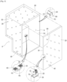
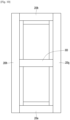
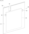
- Fig. 2 is a view schematically illustrating a vacuum adiabatic body used in the main body and the door of the refrigerator.
- a main body-side vacuum adiabatic body is illustrated in a state in which walls of top and side surfaces are removed
- a door-side vacuum adiabatic body is illustrated in a state in which a portion of a wall of a front surface is removed.
- sections of portions at conductive resistance sheets are provided are schematically illustrated for convenience of understanding.
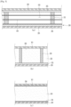
- the first plate 10 may define at least a portion of a wall for a first space provided thereto.
- the second plate 20 may define at least a portion of a wall for a second space provided thereto.
- the first space and the second space may be defined as spaces having different temperatures.
- the wall for each space may serve as not only a wall directly contacting the space but also a wall not contacting the space.
- the vacuum adiabatic body of the embodiment may also be applied to a product further having a separate wall contacting each space.
- a porous material 33 may be filled in the vacuum space 50.
- the porous material 33 may have a higher emissivity than that of the stainless material of the first and second plates 10 and 20. However, since the porous material 33 is filled in the vacuum space 50, the porous material 33 has a high efficiency for resisting the radiation heat transfer.
- the vacuum adiabatic body may be fabricated without the support 30. That is to say, the porous material 33 may perform the function of the radiation resistance sheet 32 and the function of the support 30 together.
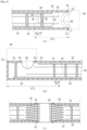
- a conductive resistance sheet proposed in Fig. 4a is applied to the main body-side vacuum adiabatic body.
- the first and second plates 10 and 20 are to be sealed so as to vacuum the inside of the vacuum adiabatic body.
- a conductive resistance sheet 60 is provided to prevent thermal conduction between different two kinds of plates.
- the conductive resistance sheet 60 In the door-side vacuum adiabatic body, it is difficult to place the conductive resistance sheet 60 on a front end of the vacuum space, i.e., an edge side surface of the vacuum space. This is because, unlike the main body, a corner edge of the door is exposed to the outside. In more detail, if the conductive resistance sheet 60 is placed on the front end of the vacuum space, the corner edge of the door is exposed to the outside, and hence there is a disadvantage in that a separate adiabatic portion has to be configured so as to thermally insulate the conductive resistance sheet 60.
- the vacuum space may resist to heat transfer by only the support 30.
- a porous material 33 may be filled with the support inside the vacuum space 50 to resist to the heat transfer.
- the heat transfer to the porous material may resist without applying the support.
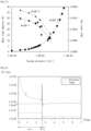
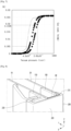
- Fig. 6 is a graph illustrating results obtained by observing a time and a pressure in a process of exhausting the inside of the vacuum adiabatic body when the support is used.
- a gas in the vacuum space 50 is exhausted by a vacuum pump while evaporating a latent gas remaining in the components of the vacuum space 50 through baking.
- the vacuum pressure reaches a certain level or more, there exists a point at which the level of the vacuum pressure does not increase any more ( ⁇ t 1 ).
- the getter is activated by disconnecting the vacuum space 50 from the vacuum pump and applying heat to the vacuum space 50 ( ⁇ t 2 ). If the getter is activated, the pressure in the vacuum space 50 decreases for a certain period of time, but then normalized to maintain a vacuum pressure having a certain level.
- the vacuum pressure that maintains the certain level after the activation of the getter is approximately 1.8 ⁇ 10 -6 Torr.
- the plate When one of the first plate and the second plate is disposed in an inner space of the third space, the plate may be represented as an inner plate. When the other one of the first plate and the second plate is disposed in an outer space of the third space, the plate may be represented as an outer plate.
- the inner space of the third space may be a storage room of the refrigerator.
- the outer space of the third space may be an outer space of the refrigerator.
- a thickness of the conductive resistance sheet may be thinner than at least one of the first plate or the second plate. The more the conductive resistance sheet decreases in thickness, the more heat transfer may decrease between the first plate and the second plate.
- One end of the conductive resistance sheet may be disposed to overlap at least a portion of the first plate. This is to provide a space for coupling one end of the conductive resistance sheet to the first plate.
- the coupling method may include welding.
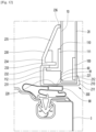
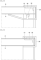
- Fig. 8 is a cross-sectional perspective view of an edge of the vacuum adiabatic body.
- a sealing frame 200 may be disposed on an outer surface of the conductive resistance sheet 60. According to the sealing frame 200, components of the door 3 or other components may not directly contact the conductive resistance sheet 60 but indirectly contact the conductive resistance sheet 60 through the sealing frame 200 to prevent the conductive resistance sheet 60 from being damaged. To allow the sealing frame 200 to prevent an impact from being applied to the conductive resistance sheet 60, the two portions may be spaced apart from each other, and a buffer may be interposed between the two portions.
- the embodiment of the vacuum adiabatic body illustrated in Fig. 8 may be preferably exemplify the vacuum adiabatic body on the main body. However, it does not exclude that it is provided to the door-side vacuum adiabatic body. Since a gasket is installed on the door 3, the sealing frame 200 may be disposed on the main body-side vacuum adiabatic body. In this case, the side surface 220 of the sealing frame 200 may further have an advantage that the gasket provides a sufficient width for the contact.
- the side surface 220 provides a wide gap corresponding to the contact area of the gasket, it is possible to effectively prevent the cool air from being lost through the contact interval between the main body 2 and the door 3. That is, when the contact width of the gasket is about 20 mm, even though the width of the side surface 220 may be about 20 mm or more, the side surface 220 may have a width about 20 mm or more to corresponding to the contact width of the gasket.
- a sealing surface 221 of the side surface having a sufficient width may be provided.
- the sealing surface 221 of the side surface may be defined as a contact surface on the side surface 220 which is in contact with the gasket sealing surface 81 when the gasket 80 contacts the side surface 220.
- the sealing surfaces 81 and 221 having a sufficient area irrespective of the adiabatic thickness of the vacuum adiabatic body. This is because even if the adiabatic thickness of the vacuum adiabatic body is narrow, and the adiabatic thickness of the vacuum adiabatic body is narrower than the gasket sealing surface 81, if the width of the side surface 220 increases, the sealing surface 221 of the side surface having the sufficient width may be obtained.
- the sealing surfaces 81 and 221 having the sufficient area may be ensured irrespective of the deformation of the portion, which may affect the deformation of the contact surface between the main body and the door. This is because it is possible to provide a predetermined clearance in and out of the side surface sealing surface 221 in designing the side surface 220 so that even if the slight deformation occurs between the sealing surfaces 81 and 221, the width and area may be maintained.
- the outward extension 211 may have a predetermined length to prevent the outer surface 210 from being separated by external weak force. That is to say, even though the outer surface 210 is forced to be pulled toward the door due to carelessness of the user, the outer surface 210 may not be completely separated from the second plate 20. However, if it is excessively long, there is difficulty in intentional removal at the time of repair, and it is preferable that the length is limited to a predetermined length because the coupling operation becomes difficult.
- the first portion coupling portion 232 and the second portion coupling portion 233 may be coupled to each other.
- the first and second portion coupling portions 232 and 233 may be provided as separate portions to be coupled to each other or may be provided as a single portion from the design stage.
- An inclined portion 235 that is inclined to the inside of the refrigerator (hereinafter, referred to as an inward inclined portion) is further provided.
- the inward inclined portion 235 may be provided so as to be inclined toward the end, that is, toward the first plate 10 toward the inside of the refrigerator.
- the inward inclined portion 235 may be provided so that a gap between the sealing frame and the first plate becomes smaller inward.
- a contact portion 236 within the refrigerator (hereinafter, referred to as an inside contact portion) is disposed on an inner end of the inward inclined portion 235.
- the inside contact portion 236 may be provided with a structure in which an end of the inward inclined portion 235 is slightly bent toward the inner surface of the second plate 10.
- the sealing due to the contact between the inner surface 230 and the second plate 10 may be completed to prevent foreign substances from being introduced.
- the second reinforcement 110 may move to the inside of the refrigerator without contacting the conductive resistance sheet 60 in order not to affect the high thermal conductive adiabatic performance of the conductive resistance sheet 60. This is done for achieving a function of a heat bridge of the conductive resistance sheet.
- the conductive resistance sheet 60 and the second reinforcement 110 do not contact each other so that the conductive adiabatic performance by the conductive resistance sheet and the strength reinforcement performance of the vacuum adiabatic body by the reinforcement are achieved at the same time.
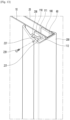
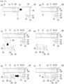
- Figs. 13 and 14 are partial cutaway perspective views illustrating the coupling of the two portions in the embodiment in which the inner surface is divided into two portions, wherein Fig. 13 is a state in which the coupling is completed, and Fig. 14 is a view illustrating the coupling process.
- a first portion coupling portion 232 is hooked with a protrusion 112 of a second reinforcement 110, and an outer surface 210 is supported by a second plate 20.
- a sealing frame 200 may be fixed to an edge of the vacuum adiabatic body.
- At least a portion of the second portion insertion recess 238 may have a size less than that of the first portion insertion portion 237.
- the two portions may be forcibly fitted.
- a protrusion and a groove may be respectively provided on/in any point after the predetermined depth.
- the two portions may be inserted further beyond the jaws to allow the two portions to be more firmly fixed.
- the worker may feel that he/she is correctly inserted through the feeling.
- the side surface 220 and the outer surface 210 rotate in the direction of the second plate 20 by using a connection point between the inner surface 230 and the side surface 220 as a rotation center. This operation may cause elastic deformation of the side surface 220.
- the component seating portion 250 on which the component 399 is seated is aligned in a predetermined direction so as to be coupled to the first portion providing the inner surface.
- the first portion coupling portion 232 and the second portion insertion recess 238 may be aligned with each other in the extension direction so that the first portion coupling portion 232 is inserted into the second portion insertion recess 238.
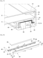
- a door coupling tool 260 is provided on the main body-side vacuum adiabatic body.
- the door coupling tool 260 may be provided in three.
- the door coupling tool 260 may be directly or indirectly fixed to the second plate 20 and/or the reinforcements 100 and 110 and/or a separate additional reinforcement (for example, an additional plate further provided on the outer surface of the second plate).
- the expression 'direct' may be referred to as a fusing method such as welding, and the expression 'indirect' may refer to a coupling method using an auxiliary coupling tool or the like instead of the fusion or the like.
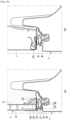
- the inward inclined portion 235 is provided to be inclined toward the inner surface of the first plate 10 at a predetermined angle ⁇ .
- the inward inclined portion may be inclined to a direction opposite to the predetermined angle ⁇ toward the inner space of the refrigerator to widely utilize a space that is close to the door. For example, more foods may be accommodated in the door, and more space for accommodating various components that are necessary for operation of the device may be defined.
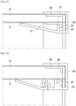
- the movement of the sealing frame 200 in the y-axis direction may be stopped through only the coupling of the inner surface 230 of the sealing frame 200 and the second reinforcement 110.
- a groove 277 is provided in the reinforcement base 276, and an end of the first portion coupling portion 232 is inserted into the groove 277 to align the sealing frame 200 with the vacuum adiabatic body.
- the sealing frame 200 may be coupled to the end of the vacuum adiabatic body.
- the movement of the sealing frame 200 in the y-axis direction may be stopped through only the coupling of the inner surface 230 of the sealing frame 200 and the second reinforcement 110.
- this embodiment is different from the above-described embodiment of Fig. 19 except that the base 111 is further provided with a reinforcement protrusion 278.
- the end of the first portion coupling portion 232 may be hooked on the reinforcement protrusion 278.
- the reinforcement protrusion 278 may be further disposed on an outer end of the base 111 to obtain a strength reinforcement effect of the main body-side vacuum adiabatic body.
- the reinforcement protrusion 278 may be applied because it provides a hook operation of the first portion coupling portion 232.
- the first reinforcement 100 is provided to reinforce the strength of the vacuum adiabatic body
- the second reinforcement 110 is not provided separately.
- an inner protrusion 281 may be provided on the inner surface of the first plate 10 so that the sealing frame 200 is coupled.
- the inner protrusion 281 may be coupled to the first plate 10 by welding or fitting. This embodiment may be applied to a case in which the sufficient strength of the main body-side vacuum adiabatic body is obtained only by the reinforcement provided in the first reinforcement 100, that is, the inside of the vacuum space 50, and the reinforcement is installed on a side of the second plate 20.
- first portion coupling groove 282 is not provided as compared with the embodiment illustrated in Fig. 22 .
- one end of the first portion coupling portion 232 may be supported by the inner protrusion 281 so that the position of the sealing frame 200 is supported.
- this embodiment may have a disadvantage in that the movement of the sealing frame 200 is stopped in only one direction, instead that the movement of the sealing frame 200 in the y-axis direction is stopped by the inner protrusion 281 and the first portion coupling groove 282 in both directions.
- an advantage that the worker conveniently works when the sealing frame 200 is coupled may be expected.
- a side of the first plate 10 is fixed, and a side of the second plate 20 is provided with a constituent in which the movement such as sliding or the like is allowed. That is to say, the second plate 20 and the outer surface 210 are allowed to be relatively slidable, and relative movement of the first plate 10 and the inner surface 230 is not allowed.
- Such the constituent may be configured opposite to each other. Hereinafter, such the constituent will be proposed.
- an outer protrusion 283 may be provided on the outer surface of the second plate 20, and an outer hook 213 may be provided on the outer surface 210 of the sealing frame 200.
- the outer hook 213 may be hooked to be supported by the outer protrusion 283.
- the inner surface 230 of the sealing frame 200 may be allowed to move with respect to the inner surface of the first plate 10 such as the sliding or the like.
- mounting and fixing of the sealing frame 200 are different only in the direction, and the same description may be applied.
- a second portion insertion recess 238 may be provided in the end of the first portion coupling portion 232 at a position corresponding to the first portion insertion portion 237 which is bent to extend to the inside of the refrigerator.
- the first portion insertion portion 237 and the second portion insertion recess 238 may be similar in size and shape to each other.
- the first portion insertion portion 237 may be inserted into the second portion insertion recess 238 and then be fitted and fixed.
- the first portion insertion portion 237 and the second portion insertion recess 238 may be coupled to each other by an additional internal cooling tool 239.
- the component fixing frame 400 may be directly coupled to the second reinforcement 110.
- Fig. 32 is a front view of the refrigerator according to an embodiment
- Fig. 33 is a rear perspective view of the refrigerator according to an embodiment.
- the cool air flowing along the cool air discharge pipe 502 passes through the mullion 300 to reach a lower end of a refrigerating compartment passage guide 550.
- the refrigerating compartment passage guide 550 may extend vertical in the refrigerating compartment R to evenly discharge the cool air inside the refrigerating compartment.
- a portion of the cool air discharged from the fan module 503 is guided along the rib 706 and discharged to freezing compartment discharge holes 703, 704, 705, and 7051.
- the cool air discharged from the freezing compartment discharge hole may be suctioned into the freezing compartment through first and second freezing compartment-side collection holes 7052 and 7053 after freezing articles within the freezing compartment.
- First and second collected cool air suction holes 707 and 708 are provided in rear upper sides of the first and second freezing compartment-side collection holes 7052 and 7053, respectively.
- the first and second freezing compartment-side collection holes 7052 and 7053 and the first and second collected cool air suction holes 707 and 708 may be provided in the freezing compartment passage guide 700 to provide paths through which the cool air used for the freezing in the freezing compartment F and the cool air used for the refrigerating in the refrigerating compartment R are introduced.
- first and second freezing compartment-side collection holes 7052 and 7053 and the first and second collected cool air suction holes 707 and 708 may be provided in a pair that are balanced at left and right sides of the evaporator.
- heat exchange efficiency of the evaporator may be improved.
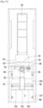
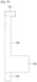
- Figs. 34 to 38 are views of the first cool air collection pipe, wherein Fig. 34 is a front view, Fig. 35 is a front view, Fig. 36 is a left view, Fig. 37 is a rear view, and Fig. 38 is a top view.
- an arrow represents a front direction.
- a flow of the cool air from the refrigerating compartment to the evaporator may sequentially include a downward flow, a lateral flow, and a backward flow.
- a rear side of the head 511 may be blocked, and an upper suction hole 518 is defined in a front side of the head 511 to receive the cool air of the refrigerating compartment.
- the upper suction hole 518 may be configured to be gradually inclined downward toward the front side. According to the head, there is no obstruction to suction the air inside the refrigerator.
- the first and second cool air collection pipes 501 and 5011 sequentially symmetrically perform the downward flow of the cool air, the lateral flow of the cool air, and the backward flow of the cool air. Accordingly, heat exchange by the evaporator may be symmetrically performed at both sides, and heat exchange efficiency may be improved.
- Fig. 41 is a view for explaining a flow of the cool air in the cool air collection pipe.
- Fig. 42 is a view for explaining a support relationship between the mullion seating frame and the cool air collection pipe
- Fig. 43 is a view for explaining a state in which the cool air collection pipe is placed in a state in which the mullion is illustrated by a virtual line.
- the cool air collection pipes 501 and 5011 may pass through the mullion 300 to extend downward.
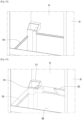
- the mullion hook protrusion 515 may be hooked on a top surface of the mullion 300 to support a weight of the mullion. It is preferable that the contact portion between the mullion and the cool air collection pipe is sealed so that an undesired heat loss due to heat exchange between the two spaces does not occur.
- cool air collection pipe according to another embodiment and a configuration of the cool air collection pipe will be described. Since the cool air collection pipe according to another embodiment and a configuration of the cool air collection pipe are similar to the cool air collection pipe and the component of the cool air collection pipe illustrated in Figs. 32 to 43 , the same description will be applied, and also, the description will be focused on differences.
- the side panel is spaced apart from both sides of the evaporator, and a rear end of the side panel may be disposed in slightly front of the evaporator for installation of the rail or the like.
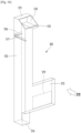
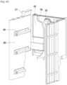
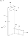
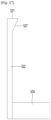
- Figs. 46 to 50 are views of the first cool air collection pipe 521, wherein Fig. 46 is a front perspective view, Fig. 47 is a front view, Fig. 48 is a rear view, Fig. 49 is a side view, and Fig. 50 is a top view.
- an arrow represents a front direction.
- a rear discharge hole 525 is provided in the rear of the side transfer portion 524 to guide the cool air to the rear side at which the evaporator is disposed.
- a flow of the cool air from the refrigerating compartment to the evaporator may sequentially include a downward flow, a first backward flow, a lateral flow, and the first backward flow.
- the first backward flow is to allow the first cool air collection pipe 521 to be led out toward a rear side of the side panel 800 so as to approach the evaporator. Accordingly, the cool air transfer duct does not occupy the inner space of the freezing compartment F, and the wider inner space of the freezing compartment F may be utilized.
- the lateral flow is performed immediately after the downward flow. This is done because the first cool air collection pipe 521 invades the inner space, or the side panel has to extend up to the side surface of the evaporator.
- the inside of the vertical transfer portion 522 may be provided to be long and narrow. This is done because the side panel 800 is provided narrowly to secure a wide inner space. As described above, the vertical transfer portion 522 is provided narrowly to correspond to the side panel 800, thereby maximally widely securing the inner space.
- the cool air in the refrigerating compartment which is suctioned through the upper suction hole 526, is transferred downward through the vertical transfer portion 522.
- the cool air may be transferred along the side panel.
- the vertical transfer portion 522 may be disposed inside the side panel 800. In some cases, the vertical transfer portion 522 is not provided separately, and an opened inner wall of the side panel 800 may provide a wall surface of the vertical transfer portion 522.
- the air transferred downward is guided backward toward the evaporator.
- the air guided backward is directed laterally toward the center of the evaporator.
- the air guided laterally is directed backward towards the evaporator.
- Figs. 52 and 53 are a cross-sectional perspective view and a cross-sectional view illustrating a relationship between the evaporator and the cool air collection pipe.
- the cool air may be transferred to the discharge pipe 502 by the fan module 503.
- the transferred cool air may pass through the mullion 300 along the cool air discharge pipe 502 to reach a lower end of the passage guide 550 of the second accommodation space.
- the reached cool air may be discharged to the second accommodation space along the passage guide 550 of the second accommodation space extending vertically from the second accommodation space.
- the discharged cool air may flow into the cool air collection pipe 501 and then be collected toward the evaporator.
- the cool air collection pipe 501 may include a head 511 having a suction hole through which the air is introduced to the second accommodation space.
- the cool air collection pipe 501 may be disposed at a side surface inside the first accommodation space.
- the cool air collection pipe 501 may further include a vertical transfer portion 512 extending vertically to transfer the air.
- the cool air collection pipe 501 may include a side transfer portion 513 extending in a lateral direction from a lower portion of the vertical transfer unit to transfer the air.
- the cool air collection pipe 501 may further include a rear discharge hole 519 provided in a rear surface of the side transfer unit to discharge the air to the evaporator.
- the cool air collection pipe is provided inside an adiabatic wall of the refrigerator.
- the wall of the first accommodation space is provided by the vacuum adiabatic body, it is difficult to form a component including the cool air duct inside the vacuum adiabatic body, that is, in the third space.
- the inner space of the first accommodation space is divided into a front space, a rear space, a side space, an upper space, and a lower space.
- the cool air collection pipe may be disposed in the other space of the front, rear, side, upper, and lower spaces.
- the cool air collection pipe may be disposed at a side of the first accommodation space.
- the cool air collection pipe is disposed in a space excluding the rear side of the first accommodation space.
- the cool air collection pipe is disposed behind the first accommodation space together with the evaporator, the cool air collection pipe or the evaporator may not be designed to be sufficiently large due to a space limitation. However, in the case of a small refrigerator having small cooling capacity, the cool air collection pipe may be disposed behind the first accommodation space together with the evaporator.
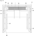
- the side panel 800 disposed on a side surface inside the first accommodation space may be further provided to cover at least a portion of the cool air collection pipe.
- the side panel When the cool air collection pipe is disposed inside the first accommodating space, the side panel may be disposed in consideration of aesthetics when the consumer uses the refrigerator.
- a component mounting portion to which components are coupled may be disposed on an outer surface of the side panel.
- the component mounting portion may include a space in which at least one of a shelf, a drawer, a temperature sensor, a lighting, a filter, a basket, an evaporator, a defrosting water tray, and a fan module is coupled.
- the side panel 800 in which at least a portion of the cool air collection pipe is provided may be provided.
- the component mounting portion to which the components are coupled may be provided on the outer surface of the side panel 800.
- a portion of the upper surface of the side panel 800 may be coupled to the mullion.
- each of the first plate and the second plate may be made of a metal material.
- the side panel may be made of a nonmetal material.
- Various components may be mounted on the side panel. At least a portion of the side panel may be mounted on an outer surface of at least one of the first plate or the second plate.
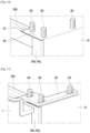
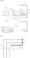
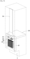
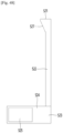
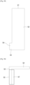
- Fig. 54 is a cross-sectional view for explaining coupling of the side panel and the vacuum adiabatic body.
- the side panel 800 may be coupled to the inner surface of the vacuum adiabatic body.
- a side coupling portion 901 may be provided on an inner surface of the first plate 10.
- the side panel 800 may be coupled to the side coupling portion 901 by using a coupling portion such as a screw.
- the side coupling portion 901 may be coupled to the first plate 10 by a method such as welding as a boss made of a metal material.
- the side coupling portion 901 may be provided on the side surface of the first plate 10.
- the side surface of the side panel 800 may be coupled to the side coupling portion 901.
- the side panel 800 may be coupled to the mullion 300.
- the side panel 800 may be coupled to the mullion seating frame 130.
- the mullion seating frame 130 may be coupled to the mullion 300 to provide a portion of the mullion.
- At least one of the shelf, the drawer, the temperature sensor, the lighting, the filter, the basket, the evaporator, the defrosting water tray, or the fan module may be coupled to the side panel 800.
- the freezing compartment passage guide 700 may be coupled to the side panel 800.
- At least one of the shelf, the drawer, the temperature sensor, the lighting, the filter, the basket, the evaporator, the defrosting water tray, or the fan module may be coupled to the freezing compartment passage guide 700.
- a rear coupling portion 902 may be further provided.
- the rear coupling portion 902 may be provided on the rear surface of the first plate 10.
- the rear surface of the side panel 800 may be coupled to the rear coupling portion 902.
- the coupling and the operation of the rear coupling portion 902 may be provided in the same manner as the side coupling portion 901.
- a rear panel may be further provided on the rear surface of the first accommodation space.
- the rear panel may provide an area for coupling various components.
- a configuration related to the rear panel will be described in detail.
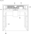
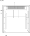
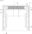
- Fig. 55 is a schematic view illustrating the inside of the refrigerator in which the rear panel is provided
- Fig. 56 is a perspective view of the rear panel.
- the side panel 800, the rail 801, and the mullion seating frame 130 are provided as in the previous embodiment.
- a rear panel 920 is coupled to the rear surface of the first accommodation space.
- the evaporator 7 and the freezing compartment passage guide 700 are further provided in front of the rear panel 920, but the illustration thereof is omitted.
- the rear panel 920 may be coupled to the inner surface of the vacuum adiabatic body, that is, the first plate 10. At least one of the shelf, the drawer, the temperature sensor, the lighting, the filter, the basket, evaporator, the defrosting water tray, the freezing compartment passage guide, or the fan module may be directly or indirectly coupled to the rear panel 920.
- At least one of the shelf, the drawer, the temperature sensor, the lighting, the filter, the basket, the evaporator, the defrosting water tray, or the fan module may be coupled to at least one of the side panel 800, the rear panel 920, or the freezing compartment passage guide 700.
- the rear panel 920 may include a rectangular flat frame 921 corresponding to an approximate shape of the rear surface of the freezing compartment and an upper bent portion 922 that is bent forward from an upper end of the flat frame 921.
- the rear surface of the flat frame 921 may be coupled to the first plate 10.
- a front surface of the flat frame 921 may be coupled to at least one of various components, which is exemplified by the evaporator.
- a refrigerant through portion 923 may be provided in the rear panel 920.
- a refrigerant pipe may pass through the refrigerant through portion 923.
- a refrigerant may flow forward and backward through the refrigerant through portion 923.
- the refrigerant condensed in a machine room 8 may flow forward through the refrigerant through portion 923 of the rear panel 920.
- the refrigerant evaporated from the evaporator 7 may flow backward through the refrigerant through portion 923 of the rear panel 920.
- the adiabatic sheet 930 may be provided between the rear panel 920 and the first plate 10.
- the adiabatic sheet 930 is illustrated as being provided only on a portion of the rear panel 920, but is not limited thereto.
- the adiabatic sheet 930 may be provided with respect to an entire surface of the rear panel 920 or may be provided on only a portion that is aligned forward and backward with the evaporator.
- the embodiments may propose the utilization method of each of the constituents of the refrigerator, which are partitioned from each other by mullions, when using the single vacuum adiabatic body.
Landscapes
- Engineering & Computer Science (AREA)
- General Engineering & Computer Science (AREA)
- Mechanical Engineering (AREA)
- Chemical & Material Sciences (AREA)
- Combustion & Propulsion (AREA)
- Physics & Mathematics (AREA)
- Thermal Sciences (AREA)
- Refrigerator Housings (AREA)
- Cold Air Circulating Systems And Constructional Details In Refrigerators (AREA)
- Thermal Insulation (AREA)
Claims (8)
- Corps adiabatique sous vide comportant :une première plaque (10) configurée pour définir au moins une partie d'une paroi pour un premier espace ;une seconde plaque (20) configurée pour définir au moins une partie d'une paroi pour un deuxième espace ayant une température différente de celle du premier espace ;un joint (61) configuré pour étanchéifier la première plaque (10) et la seconde plaque (20) de manière à fournir un troisième espace (50) qui a une température comprise entre une température du premier espace et une température du deuxième espace et est dans un état de vide ;un support (30) configuré pour maintenir le troisième espace (50) ;une tôle de résistance conductrice (60) configurée pour réduire une quantité de transfert de chaleur entre la première plaque (10) et la seconde plaque (20) ;un orifice d'échappement (40) configuré pour évacuer un gaz dans le troisième espace (50) ;une cloison (300) configurée pour diviser le premier espace en deux espaces ; etun tuyau de liaison (501) en appui sur la cloison (300) de manière à être fixé en position, le tuyau de liaison (501) étant configuré pour relier les deux espaces l'un à l'autre ;caractérisé en ce que :
le corps adiabatique sous vide comporte en outre un châssis d'appui de cloison (130) couplé à la première plaque (10) et configuré pour supporter la cloison (300), et dans lequel le tuyau de liaison (501) a une rainure (512, 516) avec laquelle le châssis d'appui de cloison (130) est accroché. - Réfrigérateur comportant :un premier espace de réception dans lequel un évaporateur (7) disposé le long d'une surface arrière, est disposé ;un second espace de réception dans lequel de l'air froid est introduit à partir du premier espace de réception ;un moteur de ventilateur disposé sur un côté de l'évaporateur (7) ;un tuyau d'évacuation (502) s'étendant à partir du premier espace de réception vers le second espace de réception ; etun tuyau de collecte d'air froid (501) s'étendant à partir du second espace de réception vers le premier espace de réception,dans lequel de l'air froid, après avoir été refroidi par l'évaporateur (7), est transféré vers le tuyau d'évacuation (502) par le moteur de ventilateur,l'air froid transféré passe à travers la cloison (300) le long du tuyau d'évacuation d'air froid pour atteindre une extrémité inférieure du guide de passage du second espace de réception,l'air froid obtenu est évacué vers le second espace de réception le long du guide de passage du second espace de réception, qui s'étend verticalement à partir du second espace de réception,l'air froid évacué est injecté dans le tuyau de collecte d'air froid (501) de manière à être collecté vers l'évaporateur (7), etle premier espace de réception est fourni sous la forme d'un corps adiabatique sous vide,dans lequel le corps adiabatique sous vide est selon la revendication 1, dans lequel les deux espaces divisés par la cloison (300) sont le premier espace de réception et le second espace de réception ;dans lequel le tuyau de collecte d'air froid (501) comporte :une tête (511) ayant un trou d'aspiration qui débouche vers le second espace de réception de sorte que l'air est introduit ;une partie de transfert verticale (512) disposée sur une surface latérale à l'intérieur du premier espace de réception, la partie de transfert verticale (512) s'étendant verticalement pour transférer de l'air ;une partie de transfert latérale (513) s'étendant latéralement à partir d'une partie inférieure de la partie de transfert verticale (512) pour transférer l'air ; etun trou d'évacuation arrière (519) défini dans une surface arrière de la partie de transfert latérale (513) pour évacuer l'air vers l'évaporateur (7).
- Réfrigérateur selon la revendication 2, comportant en outre un panneau latéral (800) disposé sur la surface latérale à l'intérieur du premier espace de réception pour couvrir au moins une partie du tuyau de collecte d'air froid (501).
- Réfrigérateur selon la revendication 2, comportant en outre un panneau latéral (800) sur lequel une partie de montage de composant ayant un intérieur, dans lequel au moins une partie du tuyau de collecte d'air froid (501) est disposée, et un extérieur, auquel un composant est couplé, est disposée.
- Réfrigérateur selon la revendication 3 ou 4, comportant en outre un guide de passage d'air froid sur un côté avant de l'évaporateur (7),dans lequel au moins un élément parmi l'évaporateur (7) ou un plateau d'eau de dégivrage est supporté sur le guide de passage d'air froid, etau moins une partie du guide de passage d'air froid est couplée au panneau latéral.
- Réfrigérateur selon la revendication 3 ou 4, dans lequel une partie d'une surface supérieure du panneau latéral est couplée à la cloison (300).
- Réfrigérateur selon la revendication 4, dans lequel la partie de montage de composant est pourvue d'un espace auquel au moins un élément parmi une tablette, un tiroir, un capteur de température, une lumière, un filtre, un balconnet, l'évaporateur (7), un plateau d'eau de dégivrage ou un module de ventilateur est couplé.
- Réfrigérateur selon la revendication 2, comportant en outre un panneau arrière (920) couplé à la surface arrière du premier espace de réception.
Priority Applications (1)
| Application Number | Priority Date | Filing Date | Title |
|---|---|---|---|
| EP25164334.2A EP4549799A3 (fr) | 2019-07-09 | 2020-07-08 | Corps adiabatique sous vide et réfrigérateur |
Applications Claiming Priority (2)
| Application Number | Priority Date | Filing Date | Title |
|---|---|---|---|
| KR1020190082641A KR102896113B1 (ko) | 2019-07-09 | 2019-07-09 | 진공단열체 및 냉장고 |
| PCT/KR2020/008966 WO2021006639A1 (fr) | 2019-07-09 | 2020-07-08 | Corps adiabatique sous vide et réfrigérateur |
Related Child Applications (1)
| Application Number | Title | Priority Date | Filing Date |
|---|---|---|---|
| EP25164334.2A Division EP4549799A3 (fr) | 2019-07-09 | 2020-07-08 | Corps adiabatique sous vide et réfrigérateur |
Publications (3)
| Publication Number | Publication Date |
|---|---|
| EP3997400A1 EP3997400A1 (fr) | 2022-05-18 |
| EP3997400A4 EP3997400A4 (fr) | 2023-07-12 |
| EP3997400B1 true EP3997400B1 (fr) | 2025-04-16 |
Family
ID=74114616
Family Applications (2)
| Application Number | Title | Priority Date | Filing Date |
|---|---|---|---|
| EP25164334.2A Pending EP4549799A3 (fr) | 2019-07-09 | 2020-07-08 | Corps adiabatique sous vide et réfrigérateur |
| EP20836297.0A Active EP3997400B1 (fr) | 2019-07-09 | 2020-07-08 | Corps adiabatique sous vide et réfrigérateur |
Family Applications Before (1)
| Application Number | Title | Priority Date | Filing Date |
|---|---|---|---|
| EP25164334.2A Pending EP4549799A3 (fr) | 2019-07-09 | 2020-07-08 | Corps adiabatique sous vide et réfrigérateur |
Country Status (6)
| Country | Link |
|---|---|
| US (2) | US12181210B2 (fr) |
| EP (2) | EP4549799A3 (fr) |
| KR (2) | KR102896113B1 (fr) |
| CN (1) | CN114080531B (fr) |
| AU (1) | AU2020311239B2 (fr) |
| WO (1) | WO2021006639A1 (fr) |
Families Citing this family (3)
| Publication number | Priority date | Publication date | Assignee | Title |
|---|---|---|---|---|
| KR20220163653A (ko) | 2021-06-03 | 2022-12-12 | 엘지전자 주식회사 | 냉장고 |
| CN115540457A (zh) * | 2022-08-18 | 2022-12-30 | 湖北美的电冰箱有限公司 | 风路组件及制冷设备 |
| DE102024107657A1 (de) | 2023-08-16 | 2025-02-20 | Liebherr-Hausgeräte Ochsenhausen GmbH | Hausgerät |
Family Cites Families (24)
| Publication number | Priority date | Publication date | Assignee | Title |
|---|---|---|---|---|
| JPH07269779A (ja) | 1994-03-28 | 1995-10-20 | Toshiba Corp | 断熱筐体及び真空断熱パネルの製造方法 |
| KR0156370B1 (ko) * | 1996-06-29 | 1999-01-15 | 배순훈 | 냉장고의 냉기순환장치 |
| CA2257703C (fr) * | 1999-01-04 | 2002-10-08 | Nedo Banicevic | Boitier d'evaporateur de refrigerateur |
| KR100343719B1 (ko) | 2000-01-14 | 2002-07-20 | 엘지전자주식회사 | 진공 단열재 패널을 구비한 냉장고 도어 |
| KR100414287B1 (ko) | 2001-11-23 | 2004-01-07 | 주식회사 엘지이아이 | 냉장고의 냉기공급장치 |
| KR100842387B1 (ko) | 2002-12-04 | 2008-07-01 | 엘지전자 주식회사 | 냉장고의 귀환덕트구조 |
| US20040226956A1 (en) | 2003-05-14 | 2004-11-18 | Jeff Brooks | Cryogenic freezer |
| KR20060006535A (ko) * | 2004-07-16 | 2006-01-19 | 삼성전자주식회사 | 냉장고 |
| KR20070042020A (ko) | 2005-10-17 | 2007-04-20 | 삼성전자주식회사 | 냉장고 |
| KR20070075835A (ko) * | 2006-01-16 | 2007-07-24 | 삼성전자주식회사 | 냉장고. |
| KR20110015322A (ko) * | 2009-08-07 | 2011-02-15 | 엘지전자 주식회사 | 진공단열재, 진공단열재를 구비한 냉장고 및 진공단열재의 제조방법 |
| JP5372878B2 (ja) | 2010-09-14 | 2013-12-18 | 日立アプライアンス株式会社 | 真空断熱材及びこれを備えた冷蔵庫 |
| JP6125163B2 (ja) | 2012-06-27 | 2017-05-10 | 東芝ライフスタイル株式会社 | 冷蔵庫 |
| KR20140009647A (ko) | 2012-07-12 | 2014-01-23 | 삼성전자주식회사 | 냉장고 및 냉장고의 제조방법 |
| KR102163292B1 (ko) | 2013-07-26 | 2020-10-08 | 삼성전자주식회사 | 진공단열재 및 이를 포함하는 냉장고 |
| KR102366410B1 (ko) * | 2014-10-16 | 2022-02-23 | 삼성전자주식회사 | 냉장고 및 이에 구비되는 진공 단열재 |
| KR102456642B1 (ko) | 2015-08-03 | 2022-10-19 | 엘지전자 주식회사 | 진공단열체 및 냉장고 |
| KR102525551B1 (ko) * | 2015-08-03 | 2023-04-25 | 엘지전자 주식회사 | 진공단열체 및 냉장고 |
| KR102604833B1 (ko) * | 2016-09-29 | 2023-11-22 | 엘지전자 주식회사 | 냉장고 |
| KR102632585B1 (ko) * | 2016-09-29 | 2024-02-02 | 엘지전자 주식회사 | 냉장고 |
| KR102671121B1 (ko) * | 2016-09-29 | 2024-05-31 | 엘지전자 주식회사 | 냉장고 |
| KR102511095B1 (ko) | 2017-12-13 | 2023-03-16 | 엘지전자 주식회사 | 진공단열체 및 냉장고 |
| KR102568737B1 (ko) | 2017-12-13 | 2023-08-21 | 엘지전자 주식회사 | 진공단열체 및 냉장고 |
| KR102530909B1 (ko) * | 2017-12-13 | 2023-05-11 | 엘지전자 주식회사 | 진공단열체 및 냉장고 |
-
2019
- 2019-07-09 KR KR1020190082641A patent/KR102896113B1/ko active Active
-
2020
- 2020-07-08 WO PCT/KR2020/008966 patent/WO2021006639A1/fr not_active Ceased
- 2020-07-08 EP EP25164334.2A patent/EP4549799A3/fr active Pending
- 2020-07-08 US US17/620,071 patent/US12181210B2/en active Active
- 2020-07-08 AU AU2020311239A patent/AU2020311239B2/en active Active
- 2020-07-08 CN CN202080049787.4A patent/CN114080531B/zh active Active
- 2020-07-08 EP EP20836297.0A patent/EP3997400B1/fr active Active
-
2024
- 2024-11-19 US US18/952,166 patent/US20250075969A1/en active Pending
-
2025
- 2025-12-01 KR KR1020250187214A patent/KR20260002353A/ko active Pending
Also Published As
| Publication number | Publication date |
|---|---|
| CN114080531A (zh) | 2022-02-22 |
| KR102896113B1 (ko) | 2025-12-05 |
| KR20210006701A (ko) | 2021-01-19 |
| EP3997400A1 (fr) | 2022-05-18 |
| EP3997400A4 (fr) | 2023-07-12 |
| EP4549799A2 (fr) | 2025-05-07 |
| EP4549799A3 (fr) | 2025-06-25 |
| WO2021006639A1 (fr) | 2021-01-14 |
| AU2020311239B2 (en) | 2026-02-12 |
| US20250075969A1 (en) | 2025-03-06 |
| US12181210B2 (en) | 2024-12-31 |
| AU2020311239A1 (en) | 2022-03-03 |
| US20220307760A1 (en) | 2022-09-29 |
| KR20260002353A (ko) | 2026-01-06 |
| CN114080531B (zh) | 2024-01-09 |
Similar Documents
| Publication | Publication Date | Title |
|---|---|---|
| EP3724568B1 (fr) | Refrigerateur avec un corps adiabatique | |
| US20250075969A1 (en) | Vacuum adiabatic body and refrigerator | |
| EP3775728B1 (fr) | Réfrigérateur | |
| EP4538621A2 (fr) | Corps adiabatique sous vide et réfrigérateur | |
| US12055342B2 (en) | Vacuum adiabatic body and refrigerator | |
| AU2022215241B2 (en) | Vacuum adiabatic body and refrigerator | |
| US12181096B2 (en) | Vacuum adiabatic body and refrigerator | |
| US20250035369A1 (en) | Vacuum adiabatic body and refrigerator | |
| US20240418435A1 (en) | Vacuum adiabatic body and refrigerator | |
| RU2837856C2 (ru) | Вакуумный адиабатический корпус и холодильник |
Legal Events
| Date | Code | Title | Description |
|---|---|---|---|
| STAA | Information on the status of an ep patent application or granted ep patent |
Free format text: STATUS: THE INTERNATIONAL PUBLICATION HAS BEEN MADE |
|
| PUAI | Public reference made under article 153(3) epc to a published international application that has entered the european phase |
Free format text: ORIGINAL CODE: 0009012 |
|
| STAA | Information on the status of an ep patent application or granted ep patent |
Free format text: STATUS: REQUEST FOR EXAMINATION WAS MADE |
|
| 17P | Request for examination filed |
Effective date: 20211220 |
|
| AK | Designated contracting states |
Kind code of ref document: A1 Designated state(s): AL AT BE BG CH CY CZ DE DK EE ES FI FR GB GR HR HU IE IS IT LI LT LU LV MC MK MT NL NO PL PT RO RS SE SI SK SM TR |
|
| DAV | Request for validation of the european patent (deleted) | ||
| DAX | Request for extension of the european patent (deleted) | ||
| A4 | Supplementary search report drawn up and despatched |
Effective date: 20230612 |
|
| RIC1 | Information provided on ipc code assigned before grant |
Ipc: F16L 59/12 20060101ALI20230605BHEP Ipc: F16L 59/065 20060101ALI20230605BHEP Ipc: F25D 23/00 20060101ALI20230605BHEP Ipc: F25D 17/06 20060101ALI20230605BHEP Ipc: F25D 23/04 20060101ALI20230605BHEP Ipc: F25D 23/08 20060101ALI20230605BHEP Ipc: F25D 23/06 20060101AFI20230605BHEP |
|
| GRAP | Despatch of communication of intention to grant a patent |
Free format text: ORIGINAL CODE: EPIDOSNIGR1 |
|
| STAA | Information on the status of an ep patent application or granted ep patent |
Free format text: STATUS: GRANT OF PATENT IS INTENDED |
|
| INTG | Intention to grant announced |
Effective date: 20241108 |
|
| GRAS | Grant fee paid |
Free format text: ORIGINAL CODE: EPIDOSNIGR3 |
|
| GRAA | (expected) grant |
Free format text: ORIGINAL CODE: 0009210 |
|
| STAA | Information on the status of an ep patent application or granted ep patent |
Free format text: STATUS: THE PATENT HAS BEEN GRANTED |
|
| AK | Designated contracting states |
Kind code of ref document: B1 Designated state(s): AL AT BE BG CH CY CZ DE DK EE ES FI FR GB GR HR HU IE IS IT LI LT LU LV MC MK MT NL NO PL PT RO RS SE SI SK SM TR |
|
| REG | Reference to a national code |
Ref country code: GB Ref legal event code: FG4D |
|
| REG | Reference to a national code |
Ref country code: CH Ref legal event code: EP Ref country code: DE Ref legal event code: R096 Ref document number: 602020049664 Country of ref document: DE |
|
| REG | Reference to a national code |
Ref country code: IE Ref legal event code: FG4D |
|
| REG | Reference to a national code |
Ref country code: NL Ref legal event code: MP Effective date: 20250416 |
|
| PG25 | Lapsed in a contracting state [announced via postgrant information from national office to epo] |
Ref country code: NL Free format text: LAPSE BECAUSE OF FAILURE TO SUBMIT A TRANSLATION OF THE DESCRIPTION OR TO PAY THE FEE WITHIN THE PRESCRIBED TIME-LIMIT Effective date: 20250416 |
|
| REG | Reference to a national code |
Ref country code: AT Ref legal event code: MK05 Ref document number: 1785932 Country of ref document: AT Kind code of ref document: T Effective date: 20250416 |
|
| PG25 | Lapsed in a contracting state [announced via postgrant information from national office to epo] |
Ref country code: ES Free format text: LAPSE BECAUSE OF FAILURE TO SUBMIT A TRANSLATION OF THE DESCRIPTION OR TO PAY THE FEE WITHIN THE PRESCRIBED TIME-LIMIT Effective date: 20250416 Ref country code: FI Free format text: LAPSE BECAUSE OF FAILURE TO SUBMIT A TRANSLATION OF THE DESCRIPTION OR TO PAY THE FEE WITHIN THE PRESCRIBED TIME-LIMIT Effective date: 20250416 Ref country code: PT Free format text: LAPSE BECAUSE OF FAILURE TO SUBMIT A TRANSLATION OF THE DESCRIPTION OR TO PAY THE FEE WITHIN THE PRESCRIBED TIME-LIMIT Effective date: 20250818 |
|
| PGFP | Annual fee paid to national office [announced via postgrant information from national office to epo] |
Ref country code: DE Payment date: 20250730 Year of fee payment: 6 |
|
| REG | Reference to a national code |
Ref country code: LT Ref legal event code: MG9D |
|
| PG25 | Lapsed in a contracting state [announced via postgrant information from national office to epo] |
Ref country code: NO Free format text: LAPSE BECAUSE OF FAILURE TO SUBMIT A TRANSLATION OF THE DESCRIPTION OR TO PAY THE FEE WITHIN THE PRESCRIBED TIME-LIMIT Effective date: 20250716 Ref country code: GR Free format text: LAPSE BECAUSE OF FAILURE TO SUBMIT A TRANSLATION OF THE DESCRIPTION OR TO PAY THE FEE WITHIN THE PRESCRIBED TIME-LIMIT Effective date: 20250717 |
|
| PG25 | Lapsed in a contracting state [announced via postgrant information from national office to epo] |
Ref country code: PL Free format text: LAPSE BECAUSE OF FAILURE TO SUBMIT A TRANSLATION OF THE DESCRIPTION OR TO PAY THE FEE WITHIN THE PRESCRIBED TIME-LIMIT Effective date: 20250416 |
|
| PG25 | Lapsed in a contracting state [announced via postgrant information from national office to epo] |
Ref country code: BG Free format text: LAPSE BECAUSE OF FAILURE TO SUBMIT A TRANSLATION OF THE DESCRIPTION OR TO PAY THE FEE WITHIN THE PRESCRIBED TIME-LIMIT Effective date: 20250416 |
|
| PGFP | Annual fee paid to national office [announced via postgrant information from national office to epo] |
Ref country code: GB Payment date: 20250724 Year of fee payment: 6 |
|
| PG25 | Lapsed in a contracting state [announced via postgrant information from national office to epo] |
Ref country code: HR Free format text: LAPSE BECAUSE OF FAILURE TO SUBMIT A TRANSLATION OF THE DESCRIPTION OR TO PAY THE FEE WITHIN THE PRESCRIBED TIME-LIMIT Effective date: 20250416 |
|
| PG25 | Lapsed in a contracting state [announced via postgrant information from national office to epo] |
Ref country code: AT Free format text: LAPSE BECAUSE OF FAILURE TO SUBMIT A TRANSLATION OF THE DESCRIPTION OR TO PAY THE FEE WITHIN THE PRESCRIBED TIME-LIMIT Effective date: 20250416 |
|
| PGFP | Annual fee paid to national office [announced via postgrant information from national office to epo] |
Ref country code: FR Payment date: 20250723 Year of fee payment: 6 |
|
| PG25 | Lapsed in a contracting state [announced via postgrant information from national office to epo] |
Ref country code: RS Free format text: LAPSE BECAUSE OF FAILURE TO SUBMIT A TRANSLATION OF THE DESCRIPTION OR TO PAY THE FEE WITHIN THE PRESCRIBED TIME-LIMIT Effective date: 20250716 |
|
| PG25 | Lapsed in a contracting state [announced via postgrant information from national office to epo] |
Ref country code: IS Free format text: LAPSE BECAUSE OF FAILURE TO SUBMIT A TRANSLATION OF THE DESCRIPTION OR TO PAY THE FEE WITHIN THE PRESCRIBED TIME-LIMIT Effective date: 20250816 |
|
| PG25 | Lapsed in a contracting state [announced via postgrant information from national office to epo] |
Ref country code: LV Free format text: LAPSE BECAUSE OF FAILURE TO SUBMIT A TRANSLATION OF THE DESCRIPTION OR TO PAY THE FEE WITHIN THE PRESCRIBED TIME-LIMIT Effective date: 20250416 |
|
| PG25 | Lapsed in a contracting state [announced via postgrant information from national office to epo] |
Ref country code: DK Free format text: LAPSE BECAUSE OF FAILURE TO SUBMIT A TRANSLATION OF THE DESCRIPTION OR TO PAY THE FEE WITHIN THE PRESCRIBED TIME-LIMIT Effective date: 20250416 Ref country code: SM Free format text: LAPSE BECAUSE OF FAILURE TO SUBMIT A TRANSLATION OF THE DESCRIPTION OR TO PAY THE FEE WITHIN THE PRESCRIBED TIME-LIMIT Effective date: 20250416 |
|
| REG | Reference to a national code |
Ref country code: DE Ref legal event code: R097 Ref document number: 602020049664 Country of ref document: DE |
|
| PG25 | Lapsed in a contracting state [announced via postgrant information from national office to epo] |
Ref country code: CZ Free format text: LAPSE BECAUSE OF FAILURE TO SUBMIT A TRANSLATION OF THE DESCRIPTION OR TO PAY THE FEE WITHIN THE PRESCRIBED TIME-LIMIT Effective date: 20250416 |
|
| PG25 | Lapsed in a contracting state [announced via postgrant information from national office to epo] |
Ref country code: EE Free format text: LAPSE BECAUSE OF FAILURE TO SUBMIT A TRANSLATION OF THE DESCRIPTION OR TO PAY THE FEE WITHIN THE PRESCRIBED TIME-LIMIT Effective date: 20250416 |
|
| PG25 | Lapsed in a contracting state [announced via postgrant information from national office to epo] |
Ref country code: SK Free format text: LAPSE BECAUSE OF FAILURE TO SUBMIT A TRANSLATION OF THE DESCRIPTION OR TO PAY THE FEE WITHIN THE PRESCRIBED TIME-LIMIT Effective date: 20250416 Ref country code: RO Free format text: LAPSE BECAUSE OF FAILURE TO SUBMIT A TRANSLATION OF THE DESCRIPTION OR TO PAY THE FEE WITHIN THE PRESCRIBED TIME-LIMIT Effective date: 20250416 |
|
| PG25 | Lapsed in a contracting state [announced via postgrant information from national office to epo] |
Ref country code: IT Free format text: LAPSE BECAUSE OF FAILURE TO SUBMIT A TRANSLATION OF THE DESCRIPTION OR TO PAY THE FEE WITHIN THE PRESCRIBED TIME-LIMIT Effective date: 20250416 |
|
| PLBE | No opposition filed within time limit |
Free format text: ORIGINAL CODE: 0009261 |
|
| STAA | Information on the status of an ep patent application or granted ep patent |
Free format text: STATUS: NO OPPOSITION FILED WITHIN TIME LIMIT |
|
| REG | Reference to a national code |
Ref country code: CH Ref legal event code: H13 Free format text: ST27 STATUS EVENT CODE: U-0-0-H10-H13 (AS PROVIDED BY THE NATIONAL OFFICE) Effective date: 20260224 |
|
| REG | Reference to a national code |
Ref country code: CH Ref legal event code: L10 Free format text: ST27 STATUS EVENT CODE: U-0-0-L10-L00 (AS PROVIDED BY THE NATIONAL OFFICE) Effective date: 20260225 |
|
| PG25 | Lapsed in a contracting state [announced via postgrant information from national office to epo] |
Ref country code: LU Free format text: LAPSE BECAUSE OF NON-PAYMENT OF DUE FEES Effective date: 20250708 |
|
| 26N | No opposition filed |
Effective date: 20260119 |
|
| REG | Reference to a national code |
Ref country code: BE Ref legal event code: MM Effective date: 20250731 |
|
| PG25 | Lapsed in a contracting state [announced via postgrant information from national office to epo] |
Ref country code: BE Free format text: LAPSE BECAUSE OF NON-PAYMENT OF DUE FEES Effective date: 20250731 |
|
| PG25 | Lapsed in a contracting state [announced via postgrant information from national office to epo] |
Ref country code: CH Free format text: LAPSE BECAUSE OF NON-PAYMENT OF DUE FEES Effective date: 20250731 |