EP3997974A1 - Rasenrad mit geringer stosswirkung - Google Patents
Rasenrad mit geringer stosswirkung Download PDFInfo
- Publication number
- EP3997974A1 EP3997974A1 EP21197942.2A EP21197942A EP3997974A1 EP 3997974 A1 EP3997974 A1 EP 3997974A1 EP 21197942 A EP21197942 A EP 21197942A EP 3997974 A1 EP3997974 A1 EP 3997974A1
- Authority
- EP
- European Patent Office
- Prior art keywords
- turf
- wheel
- wheel rim
- recited
- stem
- Prior art date
- Legal status (The legal status is an assumption and is not a legal conclusion. Google has not performed a legal analysis and makes no representation as to the accuracy of the status listed.)
- Pending
Links
Images



Classifications
-
- B—PERFORMING OPERATIONS; TRANSPORTING
- B60—VEHICLES IN GENERAL
- B60B—VEHICLE WHEELS; CASTORS; AXLES FOR WHEELS OR CASTORS; INCREASING WHEEL ADHESION
- B60B19/00—Wheels not otherwise provided for or having characteristics specified in one of the subgroups of this group
-
- A—HUMAN NECESSITIES
- A01—AGRICULTURE; FORESTRY; ANIMAL HUSBANDRY; HUNTING; TRAPPING; FISHING
- A01D—HARVESTING; MOWING
- A01D34/00—Mowers; Mowing apparatus of harvesters
- A01D34/01—Mowers; Mowing apparatus of harvesters characterised by features relating to the type of cutting apparatus
- A01D34/412—Mowers; Mowing apparatus of harvesters characterised by features relating to the type of cutting apparatus having rotating cutters
- A01D34/63—Mowers; Mowing apparatus of harvesters characterised by features relating to the type of cutting apparatus having rotating cutters having cutters rotating about a vertical axis
- A01D34/82—Other details
-
- B—PERFORMING OPERATIONS; TRANSPORTING
- B60—VEHICLES IN GENERAL
- B60B—VEHICLE WHEELS; CASTORS; AXLES FOR WHEELS OR CASTORS; INCREASING WHEEL ADHESION
- B60B15/00—Wheels or wheel attachments designed for increasing traction
- B60B15/02—Wheels with spade lugs
- B60B15/023—Wheels with spade lugs being of the broad form type
- B60B15/025—Wheels with spade lugs being of the broad form type with non-cylindrical shape
-
- B—PERFORMING OPERATIONS; TRANSPORTING
- B60—VEHICLES IN GENERAL
- B60B—VEHICLE WHEELS; CASTORS; AXLES FOR WHEELS OR CASTORS; INCREASING WHEEL ADHESION
- B60B15/00—Wheels or wheel attachments designed for increasing traction
- B60B15/02—Wheels with spade lugs
- B60B15/08—Wheels with spade lugs with spade lugs axially displaced relatively to the tread surface of the tyre
-
- A—HUMAN NECESSITIES
- A01—AGRICULTURE; FORESTRY; ANIMAL HUSBANDRY; HUNTING; TRAPPING; FISHING
- A01D—HARVESTING; MOWING
- A01D34/00—Mowers; Mowing apparatus of harvesters
- A01D34/006—Control or measuring arrangements
- A01D34/008—Control or measuring arrangements for automated or remotely controlled operation
-
- B—PERFORMING OPERATIONS; TRANSPORTING
- B60—VEHICLES IN GENERAL
- B60B—VEHICLE WHEELS; CASTORS; AXLES FOR WHEELS OR CASTORS; INCREASING WHEEL ADHESION
- B60B2900/00—Purpose of invention
- B60B2900/10—Reduction of
- B60B2900/111—Weight
-
- B—PERFORMING OPERATIONS; TRANSPORTING
- B60—VEHICLES IN GENERAL
- B60B—VEHICLE WHEELS; CASTORS; AXLES FOR WHEELS OR CASTORS; INCREASING WHEEL ADHESION
- B60B2900/00—Purpose of invention
- B60B2900/10—Reduction of
- B60B2900/112—Costs
-
- B—PERFORMING OPERATIONS; TRANSPORTING
- B60—VEHICLES IN GENERAL
- B60B—VEHICLE WHEELS; CASTORS; AXLES FOR WHEELS OR CASTORS; INCREASING WHEEL ADHESION
- B60B2900/00—Purpose of invention
- B60B2900/20—Avoidance of
- B60B2900/211—Soiling
-
- B—PERFORMING OPERATIONS; TRANSPORTING
- B60—VEHICLES IN GENERAL
- B60B—VEHICLE WHEELS; CASTORS; AXLES FOR WHEELS OR CASTORS; INCREASING WHEEL ADHESION
- B60B2900/00—Purpose of invention
- B60B2900/70—Adaptation for
- B60B2900/721—Use under adverse external conditions
Definitions
- the disclosed technology is generally directed to a wheel for mowers, and for other outdoor equipment having wheels.
- the disclosed technology relates to a low impact turf wheel to significantly reduce the adverse effects of frequent travel over turf by a lawn mower and provides resistance to build-up.
- Wheel marks and ruts in an area of mowed turf are unsightly and undesirable.
- the mower wheels carrying the full weight of the mower, compress the grass blades downward towards the underlying soil.
- the compressed grass blades cannot regain their upright posture quickly enough to be cut by the mower blade, resulting in an uneven cut.
- the turf can take on a streaked appearance. This is a particularly common problem when the grass is cut while damp or wet.
- robotic mowers operate in a random pattern spending significantly more time traveling across a lawn than in the case of a human controlled mower.
- the robotic mower travels many times over some of the same areas of a lawn, and any features of the mower that are in contact with the turf can create observable wear, and in many cases, observable damage to the turf.
- robotic mower cutting systems do not generally move as much air as conventional mowers. Without the air movement, grass that has been pushed down or laid over by the mower wheels is not drawn up into the mower cutting system.
- the disclosed technology generally described hereinafter provides for a low impact turf wheel which provides for a resistance to build-up.
- a low impact turf wheel is disclosed.
- the low impact turf wheel comprises a wheel rim having an inner and outer surface; a plurality of pegs extending radially outward from the outer surface of the wheel rim, wherein the plurality of pegs maintain the wheel rim above an area of turf; and a hub.
- the plurality of pegs provide a ground contacting tread comprising the plurality of pegs and tread voids.
- the ground contacting tread comprises less than about 50% of the surface area of the outer surface of the wheel rim.
- the ground contacting tread comprises between about 30% to 35% of the surface area of the outer surface of the wheel rim.
- the ground contacting tread comprises between about 10% to 50% of the surface area of the outer surface of the wheel rim.
- the plurality of pegs are evenly distributed about the outer surface of the wheel rim.
- the hub comprises a central hub, a branched network and a plurality of apertures.
- a turf wheel comprises a wheel rim having an inner and outer surface; a plurality of pegs extending radially outward from the outer surface of the wheel rim, wherein the peg comprises a stem, a collar and a lug, wherein the lug includes a limited surface area to provide a ground contacting tread; and a hub.
- the stem extends perpendicularly from the wheel rim.
- the collar creates an overhang extending perpendicularly outward from the stem.
- the overhang prevents build-up of turf material on or around the stem.
- the plurality of pegs maintain the wheel rim above an area of turf.
- the ground contacting tread comprises between about 10% to 50% of the total surface area of the outer surface of the wheel rim.
- the hub further comprises a central hub, a branched network and a plurality of apertures.
- a turf wheel in yet another aspect of the disclosed technology, comprises a wheel rim having an inner and outer surface; a plurality of pegs extending radially outward from the outer surface of the wheel rim, wherein the plurality of pegs maintain the wheel rim above an area of turf and provide a ground contacting tread; a non-continuous tread comprising the ground contacting tread and tread voids; and a hub.
- the ground contacting tread comprises about 30% and the tread voids comprise about 70% of the surface area of the outer surface of the wheel rim.
- the peg further comprises stem, a collar and a lug, wherein the lug includes a limited surface area of which to engage an area of turf.
- the turf wheel further comprising a contact surface ratio of about 1:3, wherein the contact surface ratio is the ratio of the ground contacting tread to the surface area of the outer surface of the wheel rim.
- the hub comprises a central portion and a branched network.
- the branched network extends radially outward from the central hub and is affixed to the wheel rim.
- the branched network includes a web structure separated by a plurality of apertures. In some embodiments, the web structure prevents a build-up of turf material in or around the central hub.
- a turf wheel comprises a wheel rim having an inner and outer surface; a plurality of pegs extending radially outward from the outer surface of the wheel rim, wherein the plurality of pegs each comprise a stem and a lug, wherein the plurality of pegs maintain the wheel rim above an area of turf and provide a ground contacting tread; a non-continuous tread comprising the ground contacting tread and tread voids; and a hub.
- the stem is substantially rectangular in shape. In some embodiments, the stem further comprises a stem surface. In some embodiments, the lug further comprises a lug face. In some embodiments, the lug face is T-shaped.
- low impact turf wheel As used herein, the terms “low impact turf wheel”, “turf wheel” and “wheel” are used interchangeably and refer to a wheel on most any autonomous mower.
- robot mower As used herein, the terms “robot mower”, “robotic mower” and “mower” are used interchangeably and refer to most any autonomous mower.
- turf As used herein, the terms “turf', “turf material”, and “material” are used interchangeably and refer to most any type of grass or turf, grass or turf clippings, wet grass or turf, leaves, small plants or branches, dirt and/or mud.
- area of turf refers to numerous types and varieties of grasses, such as those used on lawns, athletic fields, sports fields, and/or other soil, landscape or terrain.
- the disclosed technology generally described hereinafter provides for a low impact turf wheel 100.
- the tracks left by mower wheels are typically visible for an hour or more after a mowing session. Since many robotic mowers mow in a random pattern, these tracks in random directions can be objectionable to users. This effect is worsened when the soil is very wet, as the turf which is laid down by the wheels becomes coated in mud, making the track marks that much more evident.
- the low impact turf wheel 100 disclosed herein significantly reduces the adverse effects of frequent travel over turf by a robotic lawn mower.
- the features described herein reduce the long-term damage to areas of very high traffic (on-wire and in front of a charge station), and also reduce the short-term cosmetic effects that accompany conventional wheels used on existing products.
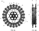
- the low impact turf wheel 100 comprises a wheel rim 2 having an inner surface 3 and an outer surface 4, a plurality of pegs 6, and a hub 8.
- the plurality of pegs 6 extend radially outward from the outer surface 4 of the wheel rim 2.
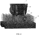
- the low impact turf wheel 100 is structured and operable to allow turf to pass through the plurality of pegs 6, yet maintain the wheel rim 2 above an area of turf, as the mower rolls across the ground without flattening, compressing or compacting the turf against the ground.
- the low impact turf wheel 100 may be an integrally-formed, one-piece member. It should be understood that the low impact turf wheel 100 can be formed of most any material sufficient to be rigid enough to provide support to the robotic mower, while also being substantially lightweight. In some embodiments, the low impact turf wheel 100 is made in one piece. In other embodiments, the wheel rim 2 is formed separately from the hub 8, wherein the wheel rim 2 and the hub 8 are attached or fixedly-attached to each other to form the turf wheel 100.
- the wheel rim 2 is substantially circular, having an inner surface 3 and an outer surface 4.
- the wheel rim 2 has a diameter and a circumference, where the outer surface 4 extends circumferentially about the wheel rim circumference.
- the plurality of pegs 6 are located on the outer surface 4 of the wheel rim 2. In some embodiments, the plurality of pegs 6 are evenly distributed about the outer surface 4 of the wheel rim 2.
- the plurality of pegs 6 are employed to maintain the outer surface 4 of the wheel rim 2 above an area of turf 10.
- To maintain the outer surface of the wheel rim above an area of turf should be understood to mean that the plurality of pegs 6 support the outer surface 4 of the wheel rim 2 in a position above the turf, so as it does not compress an area of turf, or where the outer surface 4 does not come in direct contact with the ground.
- the plurality of pegs 6 allow for turf to brush up against the outer surface 4 and to pass through the plurality of pegs 6, yet maintain the outer surface 4 of the wheel rim 2 above the turf, without flattening, compressing, or compacting an area of turf against the ground, or damaging the individual grass stems or an area of turf.
- the plurality of pegs 6 can be formed of the same or different material than that which comprises the wheel rim 2. It should also be understood that the size and quantity of pegs 6 is a function of the wheel rim 2 diameter, the mass of the object being supported (e.g. a robotic mower), and the composition of the area of turf where the low impact turf wheel 100 will be operating.
- the peg 6 comprises a stem 16, a collar 18, and a lug 20, located at the distal end of the peg 6.
- the plurality of pegs 6 provides superior traction in a number of adverse conditions due to the combination of the stem 16, collar 18, and lug 20. Traction is provided by the plurality of pegs 6, which extend radially outward from the outer surface 4 of the wheel rim 2.
- the plurality of pegs 6 may penetrate an area of turf 10, thus engaging more pegs 6 to further increase tractive forces.
- the stem 16 extends perpendicularly from the outer surface 4 of the wheel rim 2.
- the stem 16 is substantially rectangular in shape, wherein the length of the stem 16 is greater than its width. It should be understood that the stem 16 can be formed into any shape sufficient to maintain the wheel rim 2 above an area of turf 10, and also to obtain access to the turf with minimal disturbance or damage thereto.
- the collar 18 extends perpendicularly outward from the stem 16, thus creating an overhang 22.
- the collar 18 prevents turf material from slowly working up the sides of the stem 16. By preventing or minimizing turf material from building up on or around the stem 16, turf material is prevented from building up on or against the wheel rim 2, further preventing the turf wheel 100 from becoming impacted with turf material.
- the lug 20 abuttingly engages with the collar 18.
- the lug 20 is substantially trapezoidal in shape. It should be understood that the lug 20 can be any shape that will allow penetration of an area of turf to provide high grip capacity. It should also be understood that the lug 20 can be formed of the same or different material than that which comprises the stem 16.
- the lug 20 further includes a limited surface area on the lug face 24 of which directly contacts an area of turf 10.
- the lugs 20 provide a non-continuous tread surface that minimizes the impact of the wheels on the grass blades, thereby reducing or preventing damage to the turf.
- the lugs 20 lessen the number of grass blades that are compressed as the mower moves across the turf, thereby reducing wheel marks and strips of uncut grass.
- the lug face 24 can include a square, circular, triangular, rectangular, or most any other shaped frontal cross-section.
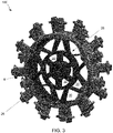
- the hub 8 is shown.
- the hub 8 comprises a central portion 26, a branched network 28 and a plurality of apertures 30.
- the central portion 26 provides for mounting of the turf wheel 100 to a robotic mower.
- the central portion 26 is configured for receiving and operatively connecting the hub 8 to a drive shaft, drive mechanism (e.g. motion drive such as a gear motor), wheel axle, or the like, (the previous list of which are not shown in figures).
- the hub 8 may only include the central portion 26.
- the branched network 28 extends radially outward from the central portion 26 and is affixed to the wheel rim 2.
- the branched network 28 comprises a web-like structure.
- the branched network 28 includes a plurality of apertures 30.
- the branched network 28 of the turf wheel 100 further reduces material costs, and provides a light-weight mower wheel.
- the turf wheel 100 provides a ground contacting tread 32 (as represented by dashed lines in FIG. 4A ).
- the ground contacting tread 32 comprises the combination of the surface area provided by the lug faces 24 that contact the ground.
- the plurality of pegs 6, which provide the lug 20 and the lug face 24, are offset from one another, yet evenly distributed about the outer surface 4, as shown in FIGS. 4A-4B .
- the plurality of pegs 6 comprises a first peg series 12 and a second peg series 14.
- the first peg series 12 and the second peg series 14 are offset from one another to provide the ground contacting tread 32.
- the ground contacting tread 32 further provides a non-continuous tread surface that prevent the turf or cut grass from joining together at the outer surface 4 of the wheel rim 2, and forming a continuous band of material. This allows the low impact turf wheel 100 to perform consistently through a range of conditions, provides resistance to build-up and reduces maintenance required of the user, and eliminates unsightly clumps of turf material in an area of turf.
- the turf wheel 100 comprises a contact surface ratio of about 1:3. It should be understood that the contact surface ratio provides the ratio of the ground contacting tread 32 (i.e. the limited ground contacting surface area provided by the combination of the lug faces 24) to the total surface area of the outer surface 4.
- tread voids 34 can include open areas of any suitable size and/or shape and in most any suitable arrangement and/or configuration.
- the ground contacting tread 32 comprises about 30% and the tread voids 34 comprise about 70% of the total surface area of the outer surface 4 of the wheel rim 2. In some embodiments, the ground contacting tread 32 includes between about 10% to 50% of the total surface area of the outer surface 4 of the wheel rim 2. In an embodiment, an appropriate contact surface ratio can be established based on the weight and/or mass of the mower, and the expected or actual turf conditions.
- the ground contacting tread 32 provides a non-continuous tread surface.
- the ground contacting tread 32 comprises between about 10% to 50% of the total surface area of the outer surface 4 of the wheel rim.
- the ground contacting tread 32 comprises between about 10% to 40% of the total surface area of the outer surface 4 of the wheel rim.
- the ground contacting tread 32 comprises about 30%-35% of the total surface area of the outer surface 4 of the wheel rim 2.
- a turf wheel 200 is shown, wherein like parts have like numerals to those in FIGS. 1-5 , plus 100.
- the low impact turf wheel 200 comprises a wheel rim 102 (not shown in figure) having an inner surface 103 (not shown in figure), an outer surface 104, and a plurality of pegs 106, wherein the plurality of pegs 106 extend radially outward from the outer surface 104.
- the peg 106 comprises a stem 116 and a lug 120, wherein the lug 120 includes a lug face 124.
- the configuration of the stem 116 and the lug 120 provides increased surface area in order to prevent the turf wheel 200 from sinking into wet, moist, or muddy soil while traversing the ground/terrain, and yet still provides superior traction.
- the stem 116 extends perpendicularly from the outer surface 104.
- the stem 116 is substantially rectangular in shape, wherein the length of the stem 116 is greater than its width.
- the stem 116 further comprises a stem surface 117, wherein the lug 120 extends radially outward from the stem surface 117.
- the stem surface 117 provides adequate support to the turf wheel 200 in order to maintain the outer surface 104 above an area of turf without sinking, becoming stuck or fixed within the wet, moist or muddy soil, or preventing a decrease in traction or efficiency.
- the stem surface 117 can support the mass of the mower without sinking into the soil.
- the lug 120 is T-shaped.
- the T-shaped lug includes a transverse rib to increase tractive force in the tangential direction.
- the lug 120 can be of most any shape that provides increased tractive force to allow the turf wheel 200 to traverse wet, moist or muddy soil/terrain.
- the ground contacting tread 132 comprises a plurality of the tread lugs 120 and lug faces 124, providing a non-continuous tread surface.
- the ground contacting tread 132 comprises between about 30% to 50% of the total surface area of the outer surface 104 of the wheel rim.
- the ground contacting tread 132 comprises between about 30% to 35% of the total surface area of the outer surface 104 of the wheel rim, in other embodiments, between about 35% to 45% of the total surface area of the outer surface 104 of the wheel rim, and in other embodiments, about 45% to 50% of the total surface area of the outer surface 104 of the wheel rim.
- the invention may comprise a low impact turf wheel according to any of the following paragraphs:
Landscapes
- Engineering & Computer Science (AREA)
- Mechanical Engineering (AREA)
- Life Sciences & Earth Sciences (AREA)
- Environmental Sciences (AREA)
- Tires In General (AREA)
Applications Claiming Priority (3)
| Application Number | Priority Date | Filing Date | Title |
|---|---|---|---|
| US201762591277P | 2017-11-28 | 2017-11-28 | |
| EP18816443.8A EP3716749B1 (de) | 2017-11-28 | 2018-11-27 | Rasenrad mit geringer einwirkung |
| PCT/US2018/062530 WO2019108505A1 (en) | 2017-11-28 | 2018-11-27 | Low impact turf wheel |
Related Parent Applications (1)
| Application Number | Title | Priority Date | Filing Date |
|---|---|---|---|
| EP18816443.8A Division EP3716749B1 (de) | 2017-11-28 | 2018-11-27 | Rasenrad mit geringer einwirkung |
Publications (1)
| Publication Number | Publication Date |
|---|---|
| EP3997974A1 true EP3997974A1 (de) | 2022-05-18 |
Family
ID=64664525
Family Applications (2)
| Application Number | Title | Priority Date | Filing Date |
|---|---|---|---|
| EP21197942.2A Pending EP3997974A1 (de) | 2017-11-28 | 2018-11-27 | Rasenrad mit geringer stosswirkung |
| EP18816443.8A Active EP3716749B1 (de) | 2017-11-28 | 2018-11-27 | Rasenrad mit geringer einwirkung |
Family Applications After (1)
| Application Number | Title | Priority Date | Filing Date |
|---|---|---|---|
| EP18816443.8A Active EP3716749B1 (de) | 2017-11-28 | 2018-11-27 | Rasenrad mit geringer einwirkung |
Country Status (6)
| Country | Link |
|---|---|
| US (3) | US10899171B2 (de) |
| EP (2) | EP3997974A1 (de) |
| CN (1) | CN111432625B (de) |
| AU (1) | AU2018374814A1 (de) |
| CA (1) | CA3080933A1 (de) |
| WO (1) | WO2019108505A1 (de) |
Cited By (1)
| Publication number | Priority date | Publication date | Assignee | Title |
|---|---|---|---|---|
| WO2026119776A1 (fr) | 2024-12-03 | 2026-06-11 | Assistance Publique – Hôpitaux De Marseille (Aphm) | Dispositif et procédé d'homogénéisation régionale de la pression trans-thoraco-pulmonaire |
Families Citing this family (15)
| Publication number | Priority date | Publication date | Assignee | Title |
|---|---|---|---|---|
| SE541243C2 (en) * | 2017-02-21 | 2019-05-14 | Husqvarna Ab | Autonomous self-propelled robotic lawnmower comprising cambered wheels |
| EP3997974A1 (de) | 2017-11-28 | 2022-05-18 | MTD Products Inc | Rasenrad mit geringer stosswirkung |
| CA3140907A1 (en) | 2019-05-24 | 2020-12-03 | Mtd Products Inc | Low impact turf wheel and wheel cleaning system |
| CA3142028A1 (en) | 2019-05-28 | 2020-12-03 | Mtd Products Inc | Calibration of power equipment utilizing objective data of equipment output |
| US12690518B2 (en) | 2021-03-10 | 2026-07-28 | Techtronic Cordless Gp | Lawnmower with airflow boost system |
| US12677737B2 (en) | 2021-03-10 | 2026-07-14 | Techtronic Cordless Gp | Lawnmowers |
| US12296694B2 (en) | 2021-03-10 | 2025-05-13 | Techtronic Cordless Gp | Lawnmowers |
| CA3181601A1 (en) | 2021-11-10 | 2023-05-10 | Techtronic Cordless Gp | Robotic lawn mowers |
| AU2023200381A1 (en) | 2022-01-31 | 2023-08-17 | Techtronic Cordless Gp | Robotic garden tool |
| CN116636380A (zh) | 2022-02-22 | 2023-08-25 | 创科无线普通合伙 | 具有刀片盖罩的园艺工具 |
| AU2023202361A1 (en) | 2022-04-20 | 2023-11-09 | Techtronic Cordless Gp | Garden tool power source compartment having drainage |
| EP4270138B1 (de) | 2022-04-28 | 2026-07-15 | Techtronic Cordless GP | Erzeugung einer virtuellen grenze für ein robotisches gartenwerkzeug |
| US12472611B2 (en) | 2022-05-31 | 2025-11-18 | Techtronic Cordless Gp | Peg driver |
| AU2023204696A1 (en) | 2022-07-19 | 2024-02-08 | Techtronic Cordless Gp | Display for controlling robotic tool |
| EP4340296B1 (de) | 2022-07-29 | 2025-04-09 | Techtronic Cordless GP | Erzeugung eines kryptoschlüssels für ein robotisches gartenwerkzeug |
Citations (8)
| Publication number | Priority date | Publication date | Assignee | Title |
|---|---|---|---|---|
| US1930835A (en) * | 1931-06-12 | 1933-10-17 | Toro Mfg Company | Lawn mower wheel |
| BE1009522A3 (nl) * | 1995-07-26 | 1997-04-01 | Den Bossche Jozef August Van | Wiel voor gazonmachines. |
| US7198333B1 (en) * | 2003-03-06 | 2007-04-03 | Ernie Freeman | Compactor cleat for land vehicles |
| GB2467956A (en) * | 2009-02-21 | 2010-08-25 | Eva Plas Injection Moulding Lt | Tyres |
| CN201980011U (zh) * | 2011-04-07 | 2011-09-21 | 谢睿旻 | 割草机用轮 |
| GB2513113A (en) * | 2013-02-26 | 2014-10-22 | Balbinder Singh Sehmi | Tyres |
| USD776169S1 (en) * | 2015-06-05 | 2017-01-10 | Mtd Products Inc | Robotic mower |
| USD794089S1 (en) * | 2015-06-05 | 2017-08-08 | Mtd Products Inc | Wheel |
Family Cites Families (21)
| Publication number | Priority date | Publication date | Assignee | Title |
|---|---|---|---|---|
| AT42352B (de) | 1909-03-08 | 1910-05-25 | Robert Nacke | Stachelwalze. |
| US3241887A (en) * | 1964-07-21 | 1966-03-22 | Samuel G Winters | Tiller drive wheel |
| US3650185A (en) * | 1970-08-12 | 1972-03-21 | Raygo Inc | Foot for compacting roller |
| US3630257A (en) * | 1970-09-15 | 1971-12-28 | Nandor Goldberger | Wheel frame with molded plastic tongues |
| US3907370A (en) | 1974-05-01 | 1975-09-23 | Creatron Ind Inc | Plastic wheel construction for utility vehicles |
| US4059229A (en) * | 1976-04-16 | 1977-11-22 | L. R. Nelson Corporation | Traveling sprinkler guide wheel assembly |
| US5769507A (en) * | 1995-10-19 | 1998-06-23 | Terra Compactor Wheel Corp. | Compactor wheel axle guard system |
| JPH1095201A (ja) * | 1996-09-25 | 1998-04-14 | Aguri Techno Yazaki Kk | ラグ付車輪 |
| CN2295620Y (zh) * | 1997-07-21 | 1998-10-28 | 孙登宁 | 一种新式车轮 |
| US5906090A (en) | 1998-01-27 | 1999-05-25 | Knudsen; Morris | Lawn mower mounted aerator wheel |
| US6334630B1 (en) | 1999-07-12 | 2002-01-01 | Randall C. Barros, Sr. | Device and method to prevent grass buildup on lawnmower wheels |
| DE102005026761A1 (de) | 2005-06-09 | 2006-12-21 | Martin Brielmaier | Fahrzeug |
| GB2470743B (en) | 2009-06-03 | 2014-04-30 | Powakaddy Internat Ltd | Winter wheel |
| IT1394979B1 (it) | 2009-07-30 | 2012-08-07 | Bernini | Ruota a contatto variabile |
| US20140047812A1 (en) | 2011-04-27 | 2014-02-20 | Husqvarna Ab | Lawn Mower Wheel and Lawn Mower with such a Wheel |
| US20150314643A1 (en) | 2014-04-30 | 2015-11-05 | Textron, Inc. | Controlled contact turf wheel for turf-care vehicle |
| CN203945900U (zh) * | 2014-07-16 | 2014-11-19 | 尹全权 | 微耕机轮胎 |
| JP6612020B2 (ja) | 2014-08-21 | 2019-11-27 | 本田技研工業株式会社 | 作業車の駆動輪 |
| CN204894970U (zh) * | 2015-07-17 | 2015-12-23 | 湖南大学 | 一种适应多种地形的多功能探测车车轮 |
| EP3997974A1 (de) * | 2017-11-28 | 2022-05-18 | MTD Products Inc | Rasenrad mit geringer stosswirkung |
| CA3140907A1 (en) * | 2019-05-24 | 2020-12-03 | Mtd Products Inc | Low impact turf wheel and wheel cleaning system |
-
2018
- 2018-11-27 EP EP21197942.2A patent/EP3997974A1/de active Pending
- 2018-11-27 US US16/201,047 patent/US10899171B2/en active Active
- 2018-11-27 AU AU2018374814A patent/AU2018374814A1/en not_active Abandoned
- 2018-11-27 EP EP18816443.8A patent/EP3716749B1/de active Active
- 2018-11-27 CN CN201880076589.XA patent/CN111432625B/zh not_active Expired - Fee Related
- 2018-11-27 WO PCT/US2018/062530 patent/WO2019108505A1/en not_active Ceased
- 2018-11-27 CA CA3080933A patent/CA3080933A1/en active Pending
-
2019
- 2019-06-27 US US16/454,253 patent/US10730344B2/en active Active
-
2020
- 2020-12-11 US US17/119,109 patent/US11691454B2/en active Active
Patent Citations (8)
| Publication number | Priority date | Publication date | Assignee | Title |
|---|---|---|---|---|
| US1930835A (en) * | 1931-06-12 | 1933-10-17 | Toro Mfg Company | Lawn mower wheel |
| BE1009522A3 (nl) * | 1995-07-26 | 1997-04-01 | Den Bossche Jozef August Van | Wiel voor gazonmachines. |
| US7198333B1 (en) * | 2003-03-06 | 2007-04-03 | Ernie Freeman | Compactor cleat for land vehicles |
| GB2467956A (en) * | 2009-02-21 | 2010-08-25 | Eva Plas Injection Moulding Lt | Tyres |
| CN201980011U (zh) * | 2011-04-07 | 2011-09-21 | 谢睿旻 | 割草机用轮 |
| GB2513113A (en) * | 2013-02-26 | 2014-10-22 | Balbinder Singh Sehmi | Tyres |
| USD776169S1 (en) * | 2015-06-05 | 2017-01-10 | Mtd Products Inc | Robotic mower |
| USD794089S1 (en) * | 2015-06-05 | 2017-08-08 | Mtd Products Inc | Wheel |
Cited By (1)
| Publication number | Priority date | Publication date | Assignee | Title |
|---|---|---|---|---|
| WO2026119776A1 (fr) | 2024-12-03 | 2026-06-11 | Assistance Publique – Hôpitaux De Marseille (Aphm) | Dispositif et procédé d'homogénéisation régionale de la pression trans-thoraco-pulmonaire |
Also Published As
| Publication number | Publication date |
|---|---|
| CN111432625A (zh) | 2020-07-17 |
| CN111432625B (zh) | 2023-02-17 |
| US20190322130A1 (en) | 2019-10-24 |
| WO2019108505A1 (en) | 2019-06-06 |
| US11691454B2 (en) | 2023-07-04 |
| AU2018374814A1 (en) | 2020-06-04 |
| EP3716749A1 (de) | 2020-10-07 |
| US20190160864A1 (en) | 2019-05-30 |
| US10730344B2 (en) | 2020-08-04 |
| EP3716749B1 (de) | 2021-09-22 |
| US20210094346A1 (en) | 2021-04-01 |
| CA3080933A1 (en) | 2019-06-06 |
| US10899171B2 (en) | 2021-01-26 |
Similar Documents
| Publication | Publication Date | Title |
|---|---|---|
| US11691454B2 (en) | Low impact turf wheel | |
| US12220940B2 (en) | Low impact turf wheel and wheel cleaning system | |
| SE544228C2 (en) | Lawnmower cutting deck, lawnmower and method of mowing a lawn | |
| KR102194296B1 (ko) | 개량된 수평 제초유닛을 갖는 자주형 복합 제초장치 | |
| US20140047812A1 (en) | Lawn Mower Wheel and Lawn Mower with such a Wheel | |
| US5546739A (en) | Radial rake device | |
| US3681903A (en) | Blade structure for mowers and edgers | |
| US3948026A (en) | Lawn mower | |
| US20080209881A1 (en) | Bauer blade | |
| US5209050A (en) | Mower wheel assembly | |
| US2901878A (en) | Lawn trimmer | |
| KR102194298B1 (ko) | 개량된 직립 제초유닛을 갖는 자주형 복합 제초장치 | |
| US20150314643A1 (en) | Controlled contact turf wheel for turf-care vehicle | |
| US11547047B2 (en) | Lawn maintenance device having offset wheels | |
| WO2022234428A1 (en) | Grass cutting tool | |
| US9622414B2 (en) | Dual purpose pivot row crop tire guard | |
| CA3101745A1 (en) | Lawn maintenance device having offset wheels | |
| CN210502110U (zh) | 一种割草机车轮 | |
| US20050034440A1 (en) | Turf bumper for turf grass mowing equipment | |
| CN207321913U (zh) | 一种手持式割草机刀片组 | |
| JPH10178846A (ja) | 野菜収穫機の車輪 | |
| JPS5844321B2 (ja) | シバヨウカンリソウチ | |
| CN111183971A (zh) | 一种风聚式除草机 | |
| KR20170028690A (ko) | 제초기 | |
| WO2016024860A1 (en) | Mowing machine |
Legal Events
| Date | Code | Title | Description |
|---|---|---|---|
| PUAI | Public reference made under article 153(3) epc to a published international application that has entered the european phase |
Free format text: ORIGINAL CODE: 0009012 |
|
| STAA | Information on the status of an ep patent application or granted ep patent |
Free format text: STATUS: THE APPLICATION HAS BEEN PUBLISHED |
|
| AC | Divisional application: reference to earlier application |
Ref document number: 3716749 Country of ref document: EP Kind code of ref document: P |
|
| AK | Designated contracting states |
Kind code of ref document: A1 Designated state(s): AL AT BE BG CH CY CZ DE DK EE ES FI FR GB GR HR HU IE IS IT LI LT LU LV MC MK MT NL NO PL PT RO RS SE SI SK SM TR |
|
| STAA | Information on the status of an ep patent application or granted ep patent |
Free format text: STATUS: REQUEST FOR EXAMINATION WAS MADE |
|
| 17P | Request for examination filed |
Effective date: 20221117 |
|
| RBV | Designated contracting states (corrected) |
Designated state(s): AL AT BE BG CH CY CZ DE DK EE ES FI FR GB GR HR HU IE IS IT LI LT LU LV MC MK MT NL NO PL PT RO RS SE SI SK SM TR |
|
| STAA | Information on the status of an ep patent application or granted ep patent |
Free format text: STATUS: EXAMINATION IS IN PROGRESS |
|
| 17Q | First examination report despatched |
Effective date: 20241202 |