EP3998010B1 - Selbstverriegelnde vorrichtung für ein endoskop - Google Patents
Selbstverriegelnde vorrichtung für ein endoskop Download PDFInfo
- Publication number
- EP3998010B1 EP3998010B1 EP20848945.0A EP20848945A EP3998010B1 EP 3998010 B1 EP3998010 B1 EP 3998010B1 EP 20848945 A EP20848945 A EP 20848945A EP 3998010 B1 EP3998010 B1 EP 3998010B1
- Authority
- EP
- European Patent Office
- Prior art keywords
- toggle
- bump
- support
- endoscope
- self
- Prior art date
- Legal status (The legal status is an assumption and is not a legal conclusion. Google has not performed a legal analysis and makes no representation as to the accuracy of the status listed.)
- Active
Links
Images



Classifications
-
- A—HUMAN NECESSITIES
- A61—MEDICAL OR VETERINARY SCIENCE; HYGIENE
- A61B—DIAGNOSIS; SURGERY; IDENTIFICATION
- A61B1/00—Instruments for performing medical examinations of the interior of cavities or tubes of the body by visual or photographical inspection, e.g. endoscopes; Illuminating arrangements therefor
- A61B1/00002—Operational features of endoscopes
-
- A—HUMAN NECESSITIES
- A61—MEDICAL OR VETERINARY SCIENCE; HYGIENE
- A61B—DIAGNOSIS; SURGERY; IDENTIFICATION
- A61B1/00—Instruments for performing medical examinations of the interior of cavities or tubes of the body by visual or photographical inspection, e.g. endoscopes; Illuminating arrangements therefor
- A61B1/005—Flexible endoscopes
- A61B1/0051—Flexible endoscopes with controlled bending of insertion part
- A61B1/0052—Constructional details of control elements, e.g. handles
-
- A—HUMAN NECESSITIES
- A61—MEDICAL OR VETERINARY SCIENCE; HYGIENE
- A61B—DIAGNOSIS; SURGERY; IDENTIFICATION
- A61B1/00—Instruments for performing medical examinations of the interior of cavities or tubes of the body by visual or photographical inspection, e.g. endoscopes; Illuminating arrangements therefor
- A61B1/00002—Operational features of endoscopes
- A61B1/00039—Operational features of endoscopes provided with input arrangements for the user
- A61B1/00042—Operational features of endoscopes provided with input arrangements for the user for mechanical operation
-
- A—HUMAN NECESSITIES
- A61—MEDICAL OR VETERINARY SCIENCE; HYGIENE
- A61B—DIAGNOSIS; SURGERY; IDENTIFICATION
- A61B1/00—Instruments for performing medical examinations of the interior of cavities or tubes of the body by visual or photographical inspection, e.g. endoscopes; Illuminating arrangements therefor
- A61B1/00147—Holding or positioning arrangements
Definitions
- the present invention relates to the technical field of endoscopes, and more particularly, to a self-locking device of an endoscope.
- endoscopes are widely used in the medical field.
- medical workers control the position of the lens of the endoscope in the human body through the toggle handle, but they often cannot let go of their hands that operate the toggle handle while observing the internal structure of the human body.
- the present invention is provided in view of the problems as mentioned above and/or existing in the prior art.
- An objective of the present invention is to provide a self-locking device of an endoscope.
- the endoscope includes: a housing, being provided outside the endoscope and hollow inside; and a toggle assembly, including a toggle support, an elastic support and a toggle handle, where the toggle handle is sleeved on the toggle support and is movable along a sleeving direction; a shaft of the toggle support passes through the housing and is connected to a first end of the elastic support on the other side; an inner side of the toggle support is provided with a toggle lever and a friction piece; a first end of the toggle lever is hinged to the toggle handle, and the other end of the toggle lever is not connected to the friction piece; the toggle lever has an L-shaped cross section, with a middle bend fixed to the toggle support; the toggle lever is hinged to the toggle support through a first pin; and when being stressed, the toggle lever is rotatable around the first pin, so as to push the friction piece to move.
- a second end of the toggle lever is provided with a fitting bump, and a first end of the friction piece is provided with a fitted bump; and a first plane is opposite a second plane, wherein the fitting bump is located on the first plane and the fitted bump is located on the second plane, wherein the fitting bump and the fitted bump are fit with each other.
- the fitting bump and the fitted bump may respectively have smooth curved surfaces.
- the toggle lever and the toggle handle may be hinged through a second pin; the first end of the toggle lever may be provided with a long oval hole; wherein the first end of the toggle lever is a connecting end; and the second pin may pass through the long oval hole to be fit with the toggle support.
- the second end of the friction piece may be fixed to a second end of the elastic support through a long shaft.
- the number of the fitting bump may be identical to the number of the fitted bump.
- the present invention has the following beneficial effects.
- the toggle handle is moved to drive the toggle lever to move along with the toggle handle, and the tail end of the toggle lever is in contact with the friction piece.
- the friction piece moves back and forth, such that the elastic support is close to and away from the housing, such that the self-locking of the toggle handle is realized through the contact between the friction piece and the tail end of the toggle lever.
- the self-locking of the endoscope is achieved by making the elastic support close to and away from the housing.
- the present invention features simple structure, low production cost and high work efficiency.
- one embodiment or “embodiments” herein refers to a particular feature, structure or characteristic that may be included in at least one implementation of the present invention.
- the "in one embodiment” appearing in different places in the specification does not refer to the same embodiment, nor is it a separate or selective embodiment mutually exclusive with other embodiments.
- a first embodiment of the present invention provides a self-locking device of an endoscope.
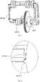
- the endoscope includes a housing 100 and a toggle assembly 200.
- the toggle assembly 200 is located outside the housing 100 and performs relative rotational motion.
- the housing 100 is provided outside the endoscope.
- the housing 100 is hollow inside to accommodate internal components and cords of the endoscope.
- the toggle assembly 200 includes a toggle support 201, an elastic support 202 and a toggle handle 203.
- the toggle handle 203 is sleeved on the toggle support 201 and is movable along a sleeving direction.
- a shaft of the toggle support 201 passes through the housing 100 and is connected to the elastic support 202 on the other side. That is to say, the toggle handle 203 is sleeved on the toggle support 201, and it is movable left and right along the toggle support 201.
- the toggle support 201 is provided with a toggle lever 201a and a friction piece 201b.
- the toggle lever 201a has an L-shaped cross section, with a middle bend fixed to the toggle support 201.
- the toggle lever 201a is hinged to the toggle support 201 through a first pin 301. When being stressed, the toggle lever 201a is rotatable around the first pin 301, so as to push the friction piece 201b to move.
- toggle lever 201a and the toggle handle 203 are hinged through a second pin 302, a connecting end of the toggle lever 201a is provided with a long oval hole, and the toggle handle 203 passes through the long oval hole to be fit with the toggle support 201. Therefore, when the toggle handle 203 moves on the toggle support 201, the toggle lever 201a provided with the long oval hole is movable up and down and left and right around the second pin 302. The left-right direction is perpendicular to the toggle support 201.
- One end of the toggle lever 201a is provided with a fitting bump 201a-1, and one end of the friction piece 201b is provided with a fitted bump 201b-1.
- a plane on which the fitting bump 201a-1 is located is opposite to a plane on which the fitted bump 201b-1 is located, so that the fitting bump and the fitted bump are fit with each other.
- the fitting bump 201a-1 and the fitted bump 201b-1 respectively have smooth curved surfaces.
- the fitting bump 201a-1 and the fitted bump 201b-1 have semicircular cross sections.
- the number of the fitting bump 201a-1 is identical to the number of the fitted bump 201b-1.
- a working principle of the self-locking device of the endoscope is as follows.
- the toggle handle 203 is placed on a left side of the toggle support 201.
- the toggle handle 203 is manually toggled to move from the left side of the toggle support 201 to a right side of the toggle support 201, and it stays at the right side of the toggle support 201.
- one end of the long oval hole of the toggle lever 201a moves relative to the second pin 302, such that the toggle lever 201a rotates around the first pin 301.
- the fitting bump 201a-1 is placed under the fitted bump 201b-1.
- the fitting bump 201a-1 is placed above the fitted bump 201b-1.
- a second embodiment of the present disclosure provides a self-locking device of an endoscope. Different from the first embodiment, in the second embodiment, one end of the friction piece 201b is fixed to the other end of the elastic support 202 through a long shaft 303.
- the endoscope includes a housing 100 and a toggle assembly 200.
- the toggle assembly 200 is located outside the housing 100 and performs relative rotational motion.
- the housing 100 is provided outside the endoscope.
- the housing 100 is hollow inside to accommodate internal components and cords of the endoscope.
- the toggle assembly 200 includes a toggle support 201, an elastic support 202 and a toggle handle 203.
- the toggle handle 203 is sleeved on the toggle support 201 and is movable along a sleeving direction.
- a shaft of the toggle support 201 passes through the housing 100 and is connected to the elastic support 202 on the other side. That is to say, the toggle handle 203 is sleeved on the toggle support 201, and it is movable left and right along the toggle support 201.
- the toggle support 201 is provided with a toggle lever 201a and a friction piece 201b.
- the toggle lever 201a has an L-shaped cross section, with a middle bend fixed to the toggle support 201.
- the toggle lever 201a is hinged to the toggle support 201 through a first pin 301. When being stressed, the toggle lever 201a is rotatable around the first pin 301, so as to push the friction piece 201b to move.
- toggle lever 201a and the toggle handle 203 are hinged through a second pin 302, a connecting end of the toggle lever 201a is provided with a long oval hole, and the toggle handle 203 passes through the long oval hole to be fit with the toggle support 201. Therefore, when the toggle handle 203 moves on the toggle support 201, the toggle lever 201a provided with the long oval hole is movable up and down and left and right around the second pin 302. The left-right direction is perpendicular to the toggle support 201.
- one end of the toggle lever 201a is provided with a fitting bump 201a-1
- one end of the friction piece 201b is provided with a fitted bump 201b-1.
- a plane on which the fitting bump 201a-1 is located is opposite to a plane on which the fitted bump 201b-1 is located, so that the fitting bump and the fitted bump are fit with each other.
- the fitting bump 201a-1 and the fitted bump 201b-1 respectively have smooth curved surfaces.
- the fitting bump 201a-1 and the fitted bump 201b-1 have semicircular cross sections.
- the number of the fitting bump 201a-1 is identical to the number of the fitted bump 201b-1.
- a working principle of the self-locking device of the endoscope is as follows.
- the toggle handle 203 is placed on a left side of the toggle support 201.
- the toggle handle 203 is manually toggled to move from the left side of the toggle support 201 to a right side of the toggle support 201, and it stays at the right side of the toggle support 201.
- one end of the long oval hole of the toggle lever 201a moves relative to the second pin 302, such that the toggle lever 201a rotates around the first pin 301.
- the fitting bump 201a-1 is placed under the fitted bump 201b-1.
- the fitting bump 201a-1 is placed above the fitted bump 201b-1.
- one end of the friction piece 201b is fixed to the other end of the elastic support 202 through the long shaft 303.
- the elastic support 202 is in contact with the housing 100, so the resistance of pulling a tail end of a cord through the toggle assembly 200 is very large.
- the tail end of the cord is self-locking without external force, and it is difficult to be pulled by the toggle assembly 200.
- the fitting bump 201a-1 moves from below the fitted bump 201b- 1 to above the fitted bump 201b-1
- the friction piece 201b pushes the long shaft 303 such that the elastic support 202 does not contact the housing 100. In this way, the resistance of pulling the tail end of the cord through the toggle assembly 200 is reduced, such that the tail end of the cord can move freely through the toggle assembly 200.
- the friction piece 201b includes a first gear 201b-2, a second gear 201b-3, a rubber sheet 201b-4, a nut 201b-5 and a bolt 201b-6.
- the bolt 201b-6 passes through the second gear 201b-3 and the rubber sheet 201b-4, and is fixed to the nut 201b-5 at the other end.
- a spring is provided between the first gear 201b-2 and the second gear 201b-3, such that the first gear 201b-2 and the second gear 201b-3 can be reset without external force.
- the fitted bump 201b-1 is provided on the first gear 201b-2.
- a working principle of the self-locking device of the endoscope is as follows.
- the toggle handle 203 is placed on a left side of the toggle support 201.
- the toggle handle 203 is manually toggled to move from the left side of the toggle support 201 to a right side of the toggle support 201, and it stays at the right side of the toggle support 201.
- the toggle handle 203 moves from the left side of the toggle support 201 to the right side of the toggle support 201, one end of the long oval hole of the toggle lever 201a moves relative to the second pin 302, such that the toggle lever 201a rotates around the first pin 301.
- the fitting bump 201a-1 is placed under the fitted bump 201b-1.
- the first gear 201b-2 meshes with the second gear 201b-3, and the adjusting nut 201b-5 is in close contact with the housing 100.
- the resistance of pulling a tail end of a cord through the toggle assembly 200 is very large.
- the tail end of the cord is self-locking without external force, and it is difficult to be pulled by the toggle assembly 200.
- the adjusting nut 201b-5 is in loose contact with the housing 100, the resistance of the toggle assembly 200 to pull the tail end of the cord is reduced, and the toggle assembly 200 can easily pull the tail end of the cord.
Landscapes
- Life Sciences & Earth Sciences (AREA)
- Health & Medical Sciences (AREA)
- Surgery (AREA)
- Engineering & Computer Science (AREA)
- Biophysics (AREA)
- Medical Informatics (AREA)
- Nuclear Medicine, Radiotherapy & Molecular Imaging (AREA)
- Optics & Photonics (AREA)
- Pathology (AREA)
- Radiology & Medical Imaging (AREA)
- Veterinary Medicine (AREA)
- Biomedical Technology (AREA)
- Heart & Thoracic Surgery (AREA)
- Physics & Mathematics (AREA)
- Molecular Biology (AREA)
- Animal Behavior & Ethology (AREA)
- General Health & Medical Sciences (AREA)
- Public Health (AREA)
- Mechanical Engineering (AREA)
- Instruments For Viewing The Inside Of Hollow Bodies (AREA)
- Endoscopes (AREA)
Claims (5)
- Selbstverriegelungsvorrichtung eines Endoskops, wobei das Endoskop umfasstein Gehäuse (100), das an der Außenseite des Endoskop bereitgestellt ist und im Inneren hohl ist; undeine Umschaltbaugruppe (200), umfassend einen Umschaltträger (201), einen elastischen Träger (202) und einen Umschaltgriff (203), wobeider Umschaltgriff (203) auf den Umschaltträger (201) gesetzt ist und der Umschaltgriff (203) in Aufsetzrichtung bewegbar ist; undein Schaft des Umschaltträgers (201) durch das Gehäuse (100) verläuft und der Schaft des Umschaltträgers (201) auf einer anderen Seite mit einem ersten Ende des elastischen Trägers (202) verbunden ist;dadurch gekennzeichnet, dasseine Innenseite des Umschaltträgers (201) mit einem Umschalthebel (201a) und einem Reibstück (201b) versehen ist und ein erstes Ende des Umschalthebels (201a) drehbar am Umschaltgriff (203) angebracht ist;der Umschalthebel (201a) einen L-förmigen Querschnitt aufweist, wobei ein mittlerer Biegungsteil am Umschaltträger (201) fixiert ist; der Umschalthebel (201a) durch einen ersten Stift (301) drehbar am Umschaltträger (201) angebracht ist; und der Umschalthebel (201a) bei Belastung um den ersten Stift (301) drehbar ist, wodurch das Reibstück (201b) bewegt wird; undein zweites Ende des Umschalthebels (201a) mit einem Eingriffshöcker (201a-1) versehen ist und ein erstes Ende des Reibstücks (201b) mit einem in Eingriff genommenen Höcker (201b-1) versehen ist; wobei eine erste Ebene einer zweiten Ebene gegenüberliegt, wobei der Eingriffshöcker (201a-1) in der ersten Ebene liegt und der in Eingriff genommene Höcker (201b-1) in der zweiten Ebene liegt, wobei der Eingriffshöcker und der in Eingriff genommene Höcker miteinander in Eingriff stehen.
- Selbstverriegelungsvorrichtung eines Endoskops nach Anspruch 1, dadurch gekennzeichnet, dass der Eingriffshöcker (201a-1) und der in Eingriff genommene Höcker (201b-1) jeweils glatte gekrümmte Flächen aufweisen.
- Selbstverriegelungsvorrichtung eines Endoskops nach Anspruch 2, dadurch gekennzeichnet, dass der Umschalthebel (201a) und der Umschaltgriff (203) durch einen zweiten Stift (302) drehbar angebracht sind; wobei das erste Ende des Umschalthebels (201a) mit einem langen ovalen Loch versehen ist, wobei das erste Ende des Umschalthebels (201a) ein Verbindungsende ist; und wobei der zweite Stift (302) für den Eingriff mit dem Umschaltträger (201) durch das lange ovale Loch verläuft.
- Selbstverriegelungsvorrichtung eines Endoskops nach einem der Ansprüche 1 bis 3, dadurch gekennzeichnet, dass ein zweites Ende des Reibstücks (201b) durch einen langen Schaft (303) an einem zweiten Ende des elastischen Trägers (202) fixiert ist.
- Selbstverriegelungsvorrichtung eines Endoskops nach Anspruch 4, dadurch gekennzeichnet, dass eine Anzahl des Eingriffshöckers (201a-1) gleich einer Anzahl des in Eingriff genommenen Höckers (201b-1) ist.
Applications Claiming Priority (2)
| Application Number | Priority Date | Filing Date | Title |
|---|---|---|---|
| CN201910726342.4A CN110432853B (zh) | 2019-08-07 | 2019-08-07 | 一种内窥镜的自锁装置 |
| PCT/CN2020/089658 WO2021022859A1 (zh) | 2019-08-07 | 2020-05-11 | 一种内窥镜的自锁装置 |
Publications (3)
| Publication Number | Publication Date |
|---|---|
| EP3998010A1 EP3998010A1 (de) | 2022-05-18 |
| EP3998010A4 EP3998010A4 (de) | 2022-09-14 |
| EP3998010B1 true EP3998010B1 (de) | 2023-03-15 |
Family
ID=68433732
Family Applications (1)
| Application Number | Title | Priority Date | Filing Date |
|---|---|---|---|
| EP20848945.0A Active EP3998010B1 (de) | 2019-08-07 | 2020-05-11 | Selbstverriegelnde vorrichtung für ein endoskop |
Country Status (6)
| Country | Link |
|---|---|
| US (1) | US11969146B2 (de) |
| EP (1) | EP3998010B1 (de) |
| JP (1) | JP7127925B2 (de) |
| CN (1) | CN110432853B (de) |
| ES (1) | ES2942304T3 (de) |
| WO (1) | WO2021022859A1 (de) |
Families Citing this family (7)
| Publication number | Priority date | Publication date | Assignee | Title |
|---|---|---|---|---|
| CN110432853B (zh) | 2019-08-07 | 2024-03-19 | 湖南省华芯医疗器械有限公司 | 一种内窥镜的自锁装置 |
| CN111012288B (zh) * | 2019-12-30 | 2025-01-07 | 湖南省华芯医疗器械有限公司 | 一体式复合管 |
| CN111202488B (zh) * | 2020-03-12 | 2025-01-07 | 湖南省华芯医疗器械有限公司 | 一种适用于内窥镜的自锁装置 |
| CN111803010B (zh) * | 2020-07-29 | 2025-01-28 | 湖南省华芯医疗器械有限公司 | 一种内窥镜自锁装置及内窥镜 |
| CN111803008B (zh) * | 2020-07-29 | 2025-01-28 | 湖南省华芯医疗器械有限公司 | 一种内窥镜自锁装置及内窥镜 |
| CN222444059U (zh) * | 2024-04-26 | 2025-02-11 | 湖南省华芯医疗器械有限公司 | 一种牵引轮自锁组件、内窥镜手柄及内窥镜 |
| CN118402745B (zh) * | 2024-06-28 | 2024-09-06 | 湖南省华芯医疗器械有限公司 | 内窥镜及其操作手柄、牵引机构 |
Family Cites Families (14)
| Publication number | Priority date | Publication date | Assignee | Title |
|---|---|---|---|---|
| DE3729131C1 (de) | 1987-09-01 | 1989-03-30 | Wolf Gmbh Richard | Steuervorrichtung zum Ablenken des distalen Endes eines Endoskopes |
| DE19650721C2 (de) * | 1996-12-06 | 1999-08-12 | Wolf Gmbh Richard | Steuervorrichtung zum Lenken des distalen Endes eines Endoskops |
| JP2004267419A (ja) | 2003-03-07 | 2004-09-30 | Pentax Corp | 電子内視鏡 |
| US8366604B2 (en) | 2009-06-03 | 2013-02-05 | Gyrus Acmi Inc. | Endoscope combined deflection control and lock |
| JP5189228B2 (ja) * | 2011-04-28 | 2013-04-24 | オリンパスメディカルシステムズ株式会社 | 内視鏡 |
| CN103654693B (zh) * | 2013-12-25 | 2016-08-17 | 武汉佑康科技有限公司 | 用于内窥镜的改进型角度调整机构 |
| CN104523321B (zh) * | 2014-12-30 | 2017-06-13 | 杭州光典医疗器械有限公司 | 带状态切换功能的锁卡装置及手术器械 |
| ES2686899T3 (es) * | 2015-06-02 | 2018-10-22 | Youcare Technology Co., Ltd. (Wuhan) | Endoscopio capaz de girar en múltiples direcciones |
| US10617283B2 (en) | 2015-06-02 | 2020-04-14 | Youcare Technology Co., Ltd. (Wuhan) | Self-locking angle adjustment mechanism for endoscope |
| US11559322B2 (en) | 2017-08-03 | 2023-01-24 | Biosense Webster (Israel) Ltd. | Multi-functional ENT tool |
| CN109077696B (zh) | 2018-08-03 | 2020-11-13 | 苏州中科先进技术研究院有限公司 | 一种内窥镜及其内窥镜蛇骨调节装置 |
| CN110432853B (zh) | 2019-08-07 | 2024-03-19 | 湖南省华芯医疗器械有限公司 | 一种内窥镜的自锁装置 |
| CN210990136U (zh) * | 2019-08-07 | 2020-07-14 | 湖南省华芯医疗器械有限公司 | 一种内窥镜的自锁装置 |
| CN110367907B (zh) | 2019-08-07 | 2024-04-12 | 湖南省华芯医疗器械有限公司 | 一种内窥镜的手持端 |
-
2019
- 2019-08-07 CN CN201910726342.4A patent/CN110432853B/zh active Active
-
2020
- 2020-05-11 US US17/633,497 patent/US11969146B2/en active Active
- 2020-05-11 JP JP2022502472A patent/JP7127925B2/ja active Active
- 2020-05-11 ES ES20848945T patent/ES2942304T3/es active Active
- 2020-05-11 WO PCT/CN2020/089658 patent/WO2021022859A1/zh not_active Ceased
- 2020-05-11 EP EP20848945.0A patent/EP3998010B1/de active Active
Also Published As
| Publication number | Publication date |
|---|---|
| JP7127925B2 (ja) | 2022-08-30 |
| US11969146B2 (en) | 2024-04-30 |
| ES2942304T3 (es) | 2023-05-31 |
| CN110432853A (zh) | 2019-11-12 |
| US20220287547A1 (en) | 2022-09-15 |
| JP2022536193A (ja) | 2022-08-12 |
| WO2021022859A1 (zh) | 2021-02-11 |
| EP3998010A4 (de) | 2022-09-14 |
| EP3998010A1 (de) | 2022-05-18 |
| CN110432853B (zh) | 2024-03-19 |
Similar Documents
| Publication | Publication Date | Title |
|---|---|---|
| EP3998010B1 (de) | Selbstverriegelnde vorrichtung für ein endoskop | |
| EP4018912B1 (de) | Selbstverriegelnde vorrichtung für ein endoskop | |
| CN109176586B (zh) | 一种基于扭转弹簧的自适应柔性手爪及机器人 | |
| US7765897B2 (en) | Ratchet wrench | |
| US20140260755A1 (en) | Multi-jointed arm assembly | |
| CN103659825B (zh) | 弯曲自锁气动欠驱动机器人手指装置 | |
| CN108555959B (zh) | 一种两自由度联动关节段与柔性机械臂 | |
| TW202009117A (zh) | 彎曲構造體及使用該構造體的關節功能部 | |
| CN104723357B (zh) | 机器人臂及包括该机器人臂的机器人 | |
| CN114052624A (zh) | 一种内窥镜的操作装置及内窥镜 | |
| KR20190131214A (ko) | 그리퍼 장치 | |
| US20150080908A1 (en) | Energy balance mechanism for flexure joint | |
| CN112518781A (zh) | 机械手及其机械手指 | |
| CN210990136U (zh) | 一种内窥镜的自锁装置 | |
| CN119567299A (zh) | 灵巧手手指、灵巧手和机器人 | |
| CN118769279A (zh) | 一种仿真机器人用机械手 | |
| CN219661757U (zh) | 调节组件及控制手柄 | |
| CN106881726B (zh) | 一种平动式机器人柔性手爪 | |
| WO2023095861A1 (ja) | 屈曲構造体及びその半製品 | |
| DE19816953A1 (de) | Anordnung zum Erzeugen von Schwenkbewegungen | |
| CN107225567A (zh) | 柔性臂的驱动装置 | |
| CN115886892A (zh) | 一种调弯装置及腕转器械 | |
| CN218934932U (zh) | 一种用于工件连接的锥套结构 | |
| DE202013103086U1 (de) | Antriebsvorrichtung mit magnetischer Anziehung | |
| CN113733072B (zh) | 一种缩放环模式的半柔性机械手 |
Legal Events
| Date | Code | Title | Description |
|---|---|---|---|
| STAA | Information on the status of an ep patent application or granted ep patent |
Free format text: STATUS: THE INTERNATIONAL PUBLICATION HAS BEEN MADE |
|
| PUAI | Public reference made under article 153(3) epc to a published international application that has entered the european phase |
Free format text: ORIGINAL CODE: 0009012 |
|
| STAA | Information on the status of an ep patent application or granted ep patent |
Free format text: STATUS: REQUEST FOR EXAMINATION WAS MADE |
|
| 17P | Request for examination filed |
Effective date: 20220210 |
|
| AK | Designated contracting states |
Kind code of ref document: A1 Designated state(s): AL AT BE BG CH CY CZ DE DK EE ES FI FR GB GR HR HU IE IS IT LI LT LU LV MC MK MT NL NO PL PT RO RS SE SI SK SM TR |
|
| A4 | Supplementary search report drawn up and despatched |
Effective date: 20220812 |
|
| RIC1 | Information provided on ipc code assigned before grant |
Ipc: A61B 1/005 20060101ALI20220808BHEP Ipc: A61B 1/00 20060101AFI20220808BHEP |
|
| DAV | Request for validation of the european patent (deleted) | ||
| DAX | Request for extension of the european patent (deleted) | ||
| GRAP | Despatch of communication of intention to grant a patent |
Free format text: ORIGINAL CODE: EPIDOSNIGR1 |
|
| STAA | Information on the status of an ep patent application or granted ep patent |
Free format text: STATUS: GRANT OF PATENT IS INTENDED |
|
| INTG | Intention to grant announced |
Effective date: 20221130 |
|
| GRAS | Grant fee paid |
Free format text: ORIGINAL CODE: EPIDOSNIGR3 |
|
| GRAA | (expected) grant |
Free format text: ORIGINAL CODE: 0009210 |
|
| STAA | Information on the status of an ep patent application or granted ep patent |
Free format text: STATUS: THE PATENT HAS BEEN GRANTED |
|
| AK | Designated contracting states |
Kind code of ref document: B1 Designated state(s): AL AT BE BG CH CY CZ DE DK EE ES FI FR GB GR HR HU IE IS IT LI LT LU LV MC MK MT NL NO PL PT RO RS SE SI SK SM TR |
|
| REG | Reference to a national code |
Ref country code: CH Ref legal event code: EP Ref country code: GB Ref legal event code: FG4D |
|
| REG | Reference to a national code |
Ref country code: DE Ref legal event code: R096 Ref document number: 602020008928 Country of ref document: DE |
|
| REG | Reference to a national code |
Ref country code: IE Ref legal event code: FG4D |
|
| REG | Reference to a national code |
Ref country code: AT Ref legal event code: REF Ref document number: 1553507 Country of ref document: AT Kind code of ref document: T Effective date: 20230415 |
|
| REG | Reference to a national code |
Ref country code: ES Ref legal event code: FG2A Ref document number: 2942304 Country of ref document: ES Kind code of ref document: T3 Effective date: 20230531 |
|
| REG | Reference to a national code |
Ref country code: LT Ref legal event code: MG9D |
|
| REG | Reference to a national code |
Ref country code: NL Ref legal event code: MP Effective date: 20230315 |
|
| PG25 | Lapsed in a contracting state [announced via postgrant information from national office to epo] |
Ref country code: RS Free format text: LAPSE BECAUSE OF FAILURE TO SUBMIT A TRANSLATION OF THE DESCRIPTION OR TO PAY THE FEE WITHIN THE PRESCRIBED TIME-LIMIT Effective date: 20230315 Ref country code: NO Free format text: LAPSE BECAUSE OF FAILURE TO SUBMIT A TRANSLATION OF THE DESCRIPTION OR TO PAY THE FEE WITHIN THE PRESCRIBED TIME-LIMIT Effective date: 20230615 Ref country code: LV Free format text: LAPSE BECAUSE OF FAILURE TO SUBMIT A TRANSLATION OF THE DESCRIPTION OR TO PAY THE FEE WITHIN THE PRESCRIBED TIME-LIMIT Effective date: 20230315 Ref country code: LT Free format text: LAPSE BECAUSE OF FAILURE TO SUBMIT A TRANSLATION OF THE DESCRIPTION OR TO PAY THE FEE WITHIN THE PRESCRIBED TIME-LIMIT Effective date: 20230315 Ref country code: HR Free format text: LAPSE BECAUSE OF FAILURE TO SUBMIT A TRANSLATION OF THE DESCRIPTION OR TO PAY THE FEE WITHIN THE PRESCRIBED TIME-LIMIT Effective date: 20230315 |
|
| REG | Reference to a national code |
Ref country code: AT Ref legal event code: MK05 Ref document number: 1553507 Country of ref document: AT Kind code of ref document: T Effective date: 20230315 |
|
| PG25 | Lapsed in a contracting state [announced via postgrant information from national office to epo] |
Ref country code: SE Free format text: LAPSE BECAUSE OF FAILURE TO SUBMIT A TRANSLATION OF THE DESCRIPTION OR TO PAY THE FEE WITHIN THE PRESCRIBED TIME-LIMIT Effective date: 20230315 Ref country code: NL Free format text: LAPSE BECAUSE OF FAILURE TO SUBMIT A TRANSLATION OF THE DESCRIPTION OR TO PAY THE FEE WITHIN THE PRESCRIBED TIME-LIMIT Effective date: 20230315 Ref country code: GR Free format text: LAPSE BECAUSE OF FAILURE TO SUBMIT A TRANSLATION OF THE DESCRIPTION OR TO PAY THE FEE WITHIN THE PRESCRIBED TIME-LIMIT Effective date: 20230616 Ref country code: FI Free format text: LAPSE BECAUSE OF FAILURE TO SUBMIT A TRANSLATION OF THE DESCRIPTION OR TO PAY THE FEE WITHIN THE PRESCRIBED TIME-LIMIT Effective date: 20230315 |
|
| PG25 | Lapsed in a contracting state [announced via postgrant information from national office to epo] |
Ref country code: SM Free format text: LAPSE BECAUSE OF FAILURE TO SUBMIT A TRANSLATION OF THE DESCRIPTION OR TO PAY THE FEE WITHIN THE PRESCRIBED TIME-LIMIT Effective date: 20230315 Ref country code: RO Free format text: LAPSE BECAUSE OF FAILURE TO SUBMIT A TRANSLATION OF THE DESCRIPTION OR TO PAY THE FEE WITHIN THE PRESCRIBED TIME-LIMIT Effective date: 20230315 Ref country code: PT Free format text: LAPSE BECAUSE OF FAILURE TO SUBMIT A TRANSLATION OF THE DESCRIPTION OR TO PAY THE FEE WITHIN THE PRESCRIBED TIME-LIMIT Effective date: 20230717 Ref country code: EE Free format text: LAPSE BECAUSE OF FAILURE TO SUBMIT A TRANSLATION OF THE DESCRIPTION OR TO PAY THE FEE WITHIN THE PRESCRIBED TIME-LIMIT Effective date: 20230315 Ref country code: CZ Free format text: LAPSE BECAUSE OF FAILURE TO SUBMIT A TRANSLATION OF THE DESCRIPTION OR TO PAY THE FEE WITHIN THE PRESCRIBED TIME-LIMIT Effective date: 20230315 Ref country code: AT Free format text: LAPSE BECAUSE OF FAILURE TO SUBMIT A TRANSLATION OF THE DESCRIPTION OR TO PAY THE FEE WITHIN THE PRESCRIBED TIME-LIMIT Effective date: 20230315 |
|
| PG25 | Lapsed in a contracting state [announced via postgrant information from national office to epo] |
Ref country code: SK Free format text: LAPSE BECAUSE OF FAILURE TO SUBMIT A TRANSLATION OF THE DESCRIPTION OR TO PAY THE FEE WITHIN THE PRESCRIBED TIME-LIMIT Effective date: 20230315 Ref country code: PL Free format text: LAPSE BECAUSE OF FAILURE TO SUBMIT A TRANSLATION OF THE DESCRIPTION OR TO PAY THE FEE WITHIN THE PRESCRIBED TIME-LIMIT Effective date: 20230315 Ref country code: IS Free format text: LAPSE BECAUSE OF FAILURE TO SUBMIT A TRANSLATION OF THE DESCRIPTION OR TO PAY THE FEE WITHIN THE PRESCRIBED TIME-LIMIT Effective date: 20230715 |
|
| REG | Reference to a national code |
Ref country code: DE Ref legal event code: R097 Ref document number: 602020008928 Country of ref document: DE |
|
| REG | Reference to a national code |
Ref country code: CH Ref legal event code: PL |
|
| PG25 | Lapsed in a contracting state [announced via postgrant information from national office to epo] |
Ref country code: MC Free format text: LAPSE BECAUSE OF FAILURE TO SUBMIT A TRANSLATION OF THE DESCRIPTION OR TO PAY THE FEE WITHIN THE PRESCRIBED TIME-LIMIT Effective date: 20230315 |
|
| PLBE | No opposition filed within time limit |
Free format text: ORIGINAL CODE: 0009261 |
|
| STAA | Information on the status of an ep patent application or granted ep patent |
Free format text: STATUS: NO OPPOSITION FILED WITHIN TIME LIMIT |
|
| REG | Reference to a national code |
Ref country code: BE Ref legal event code: MM Effective date: 20230531 |
|
| PG25 | Lapsed in a contracting state [announced via postgrant information from national office to epo] |
Ref country code: SI Free format text: LAPSE BECAUSE OF FAILURE TO SUBMIT A TRANSLATION OF THE DESCRIPTION OR TO PAY THE FEE WITHIN THE PRESCRIBED TIME-LIMIT Effective date: 20230315 Ref country code: MC Free format text: LAPSE BECAUSE OF FAILURE TO SUBMIT A TRANSLATION OF THE DESCRIPTION OR TO PAY THE FEE WITHIN THE PRESCRIBED TIME-LIMIT Effective date: 20230315 Ref country code: LU Free format text: LAPSE BECAUSE OF NON-PAYMENT OF DUE FEES Effective date: 20230511 Ref country code: LI Free format text: LAPSE BECAUSE OF NON-PAYMENT OF DUE FEES Effective date: 20230531 Ref country code: DK Free format text: LAPSE BECAUSE OF FAILURE TO SUBMIT A TRANSLATION OF THE DESCRIPTION OR TO PAY THE FEE WITHIN THE PRESCRIBED TIME-LIMIT Effective date: 20230315 Ref country code: CH Free format text: LAPSE BECAUSE OF NON-PAYMENT OF DUE FEES Effective date: 20230531 |
|
| 26N | No opposition filed |
Effective date: 20231218 |
|
| REG | Reference to a national code |
Ref country code: IE Ref legal event code: MM4A |
|
| PG25 | Lapsed in a contracting state [announced via postgrant information from national office to epo] |
Ref country code: IE Free format text: LAPSE BECAUSE OF NON-PAYMENT OF DUE FEES Effective date: 20230511 |
|
| PG25 | Lapsed in a contracting state [announced via postgrant information from national office to epo] |
Ref country code: IE Free format text: LAPSE BECAUSE OF NON-PAYMENT OF DUE FEES Effective date: 20230511 |
|
| PG25 | Lapsed in a contracting state [announced via postgrant information from national office to epo] |
Ref country code: BE Free format text: LAPSE BECAUSE OF NON-PAYMENT OF DUE FEES Effective date: 20230531 |
|
| P01 | Opt-out of the competence of the unified patent court (upc) registered |
Effective date: 20240430 |
|
| PG25 | Lapsed in a contracting state [announced via postgrant information from national office to epo] |
Ref country code: BG Free format text: LAPSE BECAUSE OF FAILURE TO SUBMIT A TRANSLATION OF THE DESCRIPTION OR TO PAY THE FEE WITHIN THE PRESCRIBED TIME-LIMIT Effective date: 20230315 |
|
| PG25 | Lapsed in a contracting state [announced via postgrant information from national office to epo] |
Ref country code: BG Free format text: LAPSE BECAUSE OF FAILURE TO SUBMIT A TRANSLATION OF THE DESCRIPTION OR TO PAY THE FEE WITHIN THE PRESCRIBED TIME-LIMIT Effective date: 20230315 |
|
| PGFP | Annual fee paid to national office [announced via postgrant information from national office to epo] |
Ref country code: DE Payment date: 20250513 Year of fee payment: 6 |
|
| PGFP | Annual fee paid to national office [announced via postgrant information from national office to epo] |
Ref country code: GB Payment date: 20250521 Year of fee payment: 6 Ref country code: ES Payment date: 20250610 Year of fee payment: 6 |
|
| PGFP | Annual fee paid to national office [announced via postgrant information from national office to epo] |
Ref country code: IT Payment date: 20250508 Year of fee payment: 6 |
|
| PGFP | Annual fee paid to national office [announced via postgrant information from national office to epo] |
Ref country code: FR Payment date: 20250530 Year of fee payment: 6 |
|
| PG25 | Lapsed in a contracting state [announced via postgrant information from national office to epo] |
Ref country code: CY Free format text: LAPSE BECAUSE OF FAILURE TO SUBMIT A TRANSLATION OF THE DESCRIPTION OR TO PAY THE FEE WITHIN THE PRESCRIBED TIME-LIMIT; INVALID AB INITIO Effective date: 20200511 |
|
| PG25 | Lapsed in a contracting state [announced via postgrant information from national office to epo] |
Ref country code: HU Free format text: LAPSE BECAUSE OF FAILURE TO SUBMIT A TRANSLATION OF THE DESCRIPTION OR TO PAY THE FEE WITHIN THE PRESCRIBED TIME-LIMIT; INVALID AB INITIO Effective date: 20200511 |
|
| PG25 | Lapsed in a contracting state [announced via postgrant information from national office to epo] |
Ref country code: TR Free format text: LAPSE BECAUSE OF FAILURE TO SUBMIT A TRANSLATION OF THE DESCRIPTION OR TO PAY THE FEE WITHIN THE PRESCRIBED TIME-LIMIT Effective date: 20230315 |