EP3998032B1 - Hochfrequenzwärmeablationssystem - Google Patents
Hochfrequenzwärmeablationssystem Download PDFInfo
- Publication number
- EP3998032B1 EP3998032B1 EP20837136.9A EP20837136A EP3998032B1 EP 3998032 B1 EP3998032 B1 EP 3998032B1 EP 20837136 A EP20837136 A EP 20837136A EP 3998032 B1 EP3998032 B1 EP 3998032B1
- Authority
- EP
- European Patent Office
- Prior art keywords
- radio frequency
- heating coil
- wpc
- thermal ablation
- frequency
- Prior art date
- Legal status (The legal status is an assumption and is not a legal conclusion. Google has not performed a legal analysis and makes no representation as to the accuracy of the status listed.)
- Active
Links
Images


Classifications
-
- A—HUMAN NECESSITIES
- A61—MEDICAL OR VETERINARY SCIENCE; HYGIENE
- A61B—DIAGNOSIS; SURGERY; IDENTIFICATION
- A61B18/00—Surgical instruments, devices or methods for transferring non-mechanical forms of energy to or from the body
- A61B18/04—Surgical instruments, devices or methods for transferring non-mechanical forms of energy to or from the body by heating
- A61B18/12—Surgical instruments, devices or methods for transferring non-mechanical forms of energy to or from the body by heating by passing a current through the tissue to be heated, e.g. high-frequency current
-
- A—HUMAN NECESSITIES
- A61—MEDICAL OR VETERINARY SCIENCE; HYGIENE
- A61B—DIAGNOSIS; SURGERY; IDENTIFICATION
- A61B18/00—Surgical instruments, devices or methods for transferring non-mechanical forms of energy to or from the body
- A61B18/04—Surgical instruments, devices or methods for transferring non-mechanical forms of energy to or from the body by heating
- A61B18/08—Surgical instruments, devices or methods for transferring non-mechanical forms of energy to or from the body by heating by means of electrically-heated probes
- A61B18/082—Probes or electrodes therefor
-
- A—HUMAN NECESSITIES
- A61—MEDICAL OR VETERINARY SCIENCE; HYGIENE
- A61B—DIAGNOSIS; SURGERY; IDENTIFICATION
- A61B18/00—Surgical instruments, devices or methods for transferring non-mechanical forms of energy to or from the body
- A61B18/04—Surgical instruments, devices or methods for transferring non-mechanical forms of energy to or from the body by heating
- A61B18/08—Surgical instruments, devices or methods for transferring non-mechanical forms of energy to or from the body by heating by means of electrically-heated probes
- A61B18/10—Power sources therefor
-
- A—HUMAN NECESSITIES
- A61—MEDICAL OR VETERINARY SCIENCE; HYGIENE
- A61B—DIAGNOSIS; SURGERY; IDENTIFICATION
- A61B17/00—Surgical instruments, devices or methods
- A61B2017/00017—Electrical control of surgical instruments
- A61B2017/00115—Electrical control of surgical instruments with audible or visual output
- A61B2017/00119—Electrical control of surgical instruments with audible or visual output alarm; indicating an abnormal situation
- A61B2017/00123—Electrical control of surgical instruments with audible or visual output alarm; indicating an abnormal situation and automatic shutdown
-
- A—HUMAN NECESSITIES
- A61—MEDICAL OR VETERINARY SCIENCE; HYGIENE
- A61B—DIAGNOSIS; SURGERY; IDENTIFICATION
- A61B18/00—Surgical instruments, devices or methods for transferring non-mechanical forms of energy to or from the body
- A61B2018/00571—Surgical instruments, devices or methods for transferring non-mechanical forms of energy to or from the body for achieving a particular surgical effect
- A61B2018/00577—Ablation
-
- A—HUMAN NECESSITIES
- A61—MEDICAL OR VETERINARY SCIENCE; HYGIENE
- A61B—DIAGNOSIS; SURGERY; IDENTIFICATION
- A61B18/00—Surgical instruments, devices or methods for transferring non-mechanical forms of energy to or from the body
- A61B2018/00636—Sensing and controlling the application of energy
- A61B2018/00642—Sensing and controlling the application of energy with feedback, i.e. closed loop control
-
- A—HUMAN NECESSITIES
- A61—MEDICAL OR VETERINARY SCIENCE; HYGIENE
- A61B—DIAGNOSIS; SURGERY; IDENTIFICATION
- A61B18/00—Surgical instruments, devices or methods for transferring non-mechanical forms of energy to or from the body
- A61B2018/00636—Sensing and controlling the application of energy
- A61B2018/00666—Sensing and controlling the application of energy using a threshold value
- A61B2018/00672—Sensing and controlling the application of energy using a threshold value lower
-
- A—HUMAN NECESSITIES
- A61—MEDICAL OR VETERINARY SCIENCE; HYGIENE
- A61B—DIAGNOSIS; SURGERY; IDENTIFICATION
- A61B18/00—Surgical instruments, devices or methods for transferring non-mechanical forms of energy to or from the body
- A61B2018/00636—Sensing and controlling the application of energy
- A61B2018/00666—Sensing and controlling the application of energy using a threshold value
- A61B2018/00678—Sensing and controlling the application of energy using a threshold value upper
-
- A—HUMAN NECESSITIES
- A61—MEDICAL OR VETERINARY SCIENCE; HYGIENE
- A61B—DIAGNOSIS; SURGERY; IDENTIFICATION
- A61B18/00—Surgical instruments, devices or methods for transferring non-mechanical forms of energy to or from the body
- A61B2018/00636—Sensing and controlling the application of energy
- A61B2018/00696—Controlled or regulated parameters
- A61B2018/00702—Power or energy
-
- A—HUMAN NECESSITIES
- A61—MEDICAL OR VETERINARY SCIENCE; HYGIENE
- A61B—DIAGNOSIS; SURGERY; IDENTIFICATION
- A61B18/00—Surgical instruments, devices or methods for transferring non-mechanical forms of energy to or from the body
- A61B2018/00636—Sensing and controlling the application of energy
- A61B2018/00696—Controlled or regulated parameters
- A61B2018/00732—Frequency
-
- A—HUMAN NECESSITIES
- A61—MEDICAL OR VETERINARY SCIENCE; HYGIENE
- A61B—DIAGNOSIS; SURGERY; IDENTIFICATION
- A61B18/00—Surgical instruments, devices or methods for transferring non-mechanical forms of energy to or from the body
- A61B2018/00636—Sensing and controlling the application of energy
- A61B2018/00773—Sensed parameters
- A61B2018/00827—Current
-
- A—HUMAN NECESSITIES
- A61—MEDICAL OR VETERINARY SCIENCE; HYGIENE
- A61B—DIAGNOSIS; SURGERY; IDENTIFICATION
- A61B18/00—Surgical instruments, devices or methods for transferring non-mechanical forms of energy to or from the body
- A61B2018/00636—Sensing and controlling the application of energy
- A61B2018/00773—Sensed parameters
- A61B2018/00869—Phase
-
- A—HUMAN NECESSITIES
- A61—MEDICAL OR VETERINARY SCIENCE; HYGIENE
- A61B—DIAGNOSIS; SURGERY; IDENTIFICATION
- A61B18/00—Surgical instruments, devices or methods for transferring non-mechanical forms of energy to or from the body
- A61B2018/00636—Sensing and controlling the application of energy
- A61B2018/00773—Sensed parameters
- A61B2018/00875—Resistance or impedance
-
- A—HUMAN NECESSITIES
- A61—MEDICAL OR VETERINARY SCIENCE; HYGIENE
- A61B—DIAGNOSIS; SURGERY; IDENTIFICATION
- A61B18/00—Surgical instruments, devices or methods for transferring non-mechanical forms of energy to or from the body
- A61B2018/00636—Sensing and controlling the application of energy
- A61B2018/00773—Sensed parameters
- A61B2018/00892—Voltage
-
- A—HUMAN NECESSITIES
- A61—MEDICAL OR VETERINARY SCIENCE; HYGIENE
- A61B—DIAGNOSIS; SURGERY; IDENTIFICATION
- A61B18/00—Surgical instruments, devices or methods for transferring non-mechanical forms of energy to or from the body
- A61B2018/00988—Means for storing information, e.g. calibration constants, or for preventing excessive use, e.g. usage, service life counter
-
- A—HUMAN NECESSITIES
- A61—MEDICAL OR VETERINARY SCIENCE; HYGIENE
- A61B—DIAGNOSIS; SURGERY; IDENTIFICATION
- A61B90/00—Instruments, implements or accessories specially adapted for surgery or diagnosis and not covered by any of the groups A61B1/00 - A61B50/00, e.g. for luxation treatment or for protecting wound edges
- A61B90/06—Measuring instruments not otherwise provided for
- A61B2090/064—Measuring instruments not otherwise provided for for measuring force, pressure or mechanical tension
- A61B2090/065—Measuring instruments not otherwise provided for for measuring force, pressure or mechanical tension for measuring contact or contact pressure
Definitions
- This application generally relates to ablation technology, and more particularly, to radio frequency thermal ablation technology.
- Radio frequency ablation is a widely used minimally invasive technology.
- radio frequency ablation has been applied to a variety of diseases such as arrhythmia, cancer tumors, and even skin defects.
- radio frequency thermal ablation technology radio frequency energy is not directly applied onto the human body, but is converted into heat energy inside the device, and then transferred to the human body to produce thermal ablation effects. Because this technology has less trauma to the human body and the ablation method can be precisely controlled by an electronic system, it has become a technology that is commonly used in powered minimally invasive surgery.
- radio frequency ablation catheters are currently used to ablate bronchial nerves to treat asthma, to ablate prostate tissue through the urethra to treat enlarged prostate, to ablate peripheral blood vessels to shrink them, to ablate surface tissues of the esophagus to treat esophageal cancer, and to ablate surface tissues of uterus to treat uterine cancer, etc.
- These organs of the human body such as blood vessels, bronchi, urethra, esophagus, uterus, etc., are basically slender and tubular structures, and they have similar requirements on the appearance, function and performance of a radio frequency catheter.
- Radio frequency thermal ablation probes mostly use closed and insulated resistive heating elements, such as patents US7837677 , EP1906853 , US2017/0202600A1 , EP2662044 , and US10357305 . These methods do not create an electric current circulation into human tissue. Therefore, the common practice in this field is to ignore the influence of external tissues on the characteristics of resistive windings and only rely on simple temperature feedback control for treatment.
- US2017/238991A1 describes an electrosurgical element with an electrically conductive sheet is laminated to an electrically insulative sheet. An electrode is formed on the electrically conductive sheet. An electrically insulative layer is formed on a tissue contacting surface of the electrode. The individual electrodes are separated from the laminated electrically insulative sheet and the electrically conductive sheet.
- a flexible circuit is vacuum formed to create a desired profile. The vacuum formed flexible circuit is trimmed. The trimmed vacuum formed flexible circuit is attached to a jaw member of a clamp jaw assembly.
- EP3093626A1 relates to a telemetry system for the wireless measurement of a quantity, comprising at least a passive transducer sensitive to a variation of said quantity and a reading unit coupled to said passive transducer and suitable to detect, condition and process information of a measurement coming from the passive transducer.
- Each passive transducer comprises a resistive transduction sensitive element, a calibration capacitor, suitable to define a working frequency of the system, and a first coupling inductor.
- the reading unit comprises a second coupling inductor suitable to realize an inductive coupling with said first coupling inductor, and detection means suitable to detect a variation of amplitude of the real part of the impedance of the assembly constituted by the passive transducer and the second coupling inductor, at the working frequency, said amplitude of the real part of the impedance depending on the resistance value of the sensitive element.
- the area heated by thermal ablation is generally not just a point, but an area.
- the most typical failure is that the organ wall is tightly attached to the heating winding surface due to accidental high temperature when the sensing means are insufficient, and the treatment continues due to the lack of effective sensing means, resulting in stickiness and even carbonization, and even medical accidents.
- the purpose of this application is to provide a radio frequency thermal ablation system, which can use the parasitic capacitance between turns of the closed winding to monitor the state of the aperture shrinkage of the tubular organ during the thermal ablation process, and then configure the monitoring by designing the winding sensitivity operation point, enhance the sensitivity of detecting the inter-turn winding parasitic capacitance (WPC), thereby effectively control the treatment process and make key treatment parameters such as the distance of the organ tube wall controllable in the thermal ablation process.
- WPC inter-turn winding parasitic capacitance
- This invention discloses a radio frequency thermal ablation system comprising:
- said WPC detecting device monitors said change of WPC by monitoring the vector voltage and current on the said heating coil.
- said control device computes the WPC value based on the detected vector voltage and current of said heating coil, and extracting the impedance phase of the WPC combined with the coil inductance; if said phase is within a specified range, said control method stops said radio frequency generator from outputting radio frequency power.
- the output frequency of said control device is continuously adjustable, and said control device searches and adjusts the frequency of the radio frequency power output from said radio frequency generator in a preset frequency range, so that the difference between said frequency and the resonant frequency of said complex impedance is less than a preset threshold.
- the operating frequency range includes the frequency range in which the phase of the complex impedance of the heating coil shifts from -90 degrees to 90 degrees after said parasitic capacitance is cancelled.
- said inter-turn spacing of the heating coil satisfies the following condition: the resonance frequency caused by the inductance of said heating coil and expected WPC is within said frequency range, wherein said expected WPC is the inter-turn parasitic capacitance of said heating coil when the distance between blood vessel tissue and said thermal ablation catheter is within a pre-set range.
- said radio frequency thermal ablation system comprises flash memory for storing pre-calibrated resonant frequency that is readable as the target resonant frequency to said control device.
- a control method of a thermal ablation system comprises said thermal ablation catheter that further comprises an insulated inductive heating coil; said control method configures the operating frequency, and enhances the sensitivity of WPC detection, based on the inductivity of the heating coil;
- Said monitoring the change of WPC further may comprise: monitoring said change of WPC by monitoring the vector voltage and current on the said heating coil; said method of controlling the output radio frequency power from said radio frequency generator, based on the detected change in WPC, which further comprises: computing the WPC value based on the detected vector voltage and current of said heating coil, and extracting the impedance phase of the WPC combined with the coil inductance; if said phase is within a specified range, said control method stops said radio frequency generator from outputting radio frequency power.
- said control method may further comprise: in the pre-set operating frequency range, searching and adjusting the output frequency from said radio frequency generator, reducing the difference between said operating frequency and the resonant frequency of said complex impedance to be less than a pre-set threshold.
- the first step is to design an inductive insulated heating coil based on the WPC variation range during treatment.
- This inductive insulated heating coil is wound to centralize the inductance, where the inductance of the insulated heating coil is centralized instead of separated.
- the centralized design enables focused sensing while heating.
- parasitic capacitance exists due to the wall of the tubular organ and the coagulating blood liquid.
- WPC parasitic capacitance
- the WPC gradually increases to resonate with the inductance, and the phase variation of the overall complex impedance with respect to frequency increases. This boosts the sensitivity of detecting the phase of the overall complex impedance, and therefore boosts the sensitivity of deriving WPC based on the impedance phase.
- the capability of measuring the WPC in real time is enhanced. Therefore, it can be more accurately monitored and controlled WPC, and then detected and controlled the degree of organ wall approaching the thermal ablation catheter or the degree of surrounding body fluid coagulation based on monitoring the change of complex impedance of said inductive insulated heating coil in the thermal ablation treatment process.
- the thermal ablation treatment process can be controlled and optimized according to the monitoring results. For example, when the complex impedance is close to the preset value, it can be judged that the tubular organ wall atrophy closing to the ablation catheter, and the control device can reduce the power output and the shrinkage of the wall, so as to control the treatment effect more smoothly and accurately.
- this application is implemented as searching and adjusting the output frequency of said radio frequency generator over the preset frequency range, reducing the difference between said operating frequency and the resonant frequency of said complex impedance to be less than a pre-set threshold.
- the inter-tern spacing of the insulated heating coil is adjusted to have the resonant frequency of said inductance of the insulated heating coil and the expected WPC combined to be in said operating frequency range, wherein the expected WPC is the parasitic capacitance when the distance from the wall of the tubular organ to the catheter is within a preset range.
- vascular thermal ablation technology generally relies on adjusting the heating time at a certain temperature to control the degree of vessel shrinkage. Therefore, the current treatment devices on the market generally control two parameters: heating temperature and heating time. These two are indirectly related to the parameters that need to be controlled during treatment, such as the degree of tubular wall contraction or the degree of body fluid coagulation. Simply put, the longer the heating time, the higher the degree of wall shrinkage of the tubular organ. However, because of the different shapes and sizes of organs, heating time and temperature cannot uniquely determine the degree of tubular wall contraction or body fluid condensation. Empirically controlling the heating temperature and time can lead to differences in therapeutic effects or even out of control.
- the heating temperature and time are controlled, if the tube wall shrinks faster than expected, continued heating may cause damage and carbonization of the tubular organ, or make the ablation catheter stick to the inner wall of the tubular organ and cannot be pulled out, causing medical accidents; and when the heating time is too short It will lead to inadequate treatment, incomplete closure of blood vessels, failure to accomplish the purpose of surgery.
- the blood vessel's own condition and surrounding environment are different and variable during the treatment. For example, although the surgeons will try to expel the blood in the blood vessel to be treated through pressing and tumescent anesthesia, there still is certain amount of blood left in the blood vessel, surrounding the heating element, forming an additional load and cooling the heating element.
- the first embodiment of this application involves a radio frequency thermal ablation system, the structure of which is shown in FIG. 1 .
- the radio frequency thermal ablation system comprises a thermal ablation catheter and a radio frequency generator, wherein the thermal ablation catheter comprises an insulated inductive heating coil.
- the radio frequency generator outputs radio frequency power to the insulated heating coil for heating.
- the inductance is used to configure the frequency operating point during detection to enhance the sensitivity of detecting parasitic capacitance between winding turns.
- the exemplary radio frequency thermal ablation catheter in FIG. 2 , it comprises a strain relief ring 205 and an ablation body 201 as an effective treatment segment.
- the ablation body 201 comprises a heating element 202, a tubing 203 and a movable positioner 204, wherein the heating element 202 is a closed, insulated inductive coil connected to the tubing 203.
- the movable positioner 204 is installed on the tubing 203.
- the insulated heating coil prevents electrical current from flowing into human tissue. It shall be understood that the connection between the insulated inductive heating coil and the tubing 203 in this embodiment can be a fixed connection or can be any other reliable forms of connection.
- the exemplary radio frequency thermal ablation can also comprise a strain relief ring 205, a handle button 206, a handle 207, an inner tube connector 208, a wire 209, and a wire connector 210 etc.
- the exemplary radio frequency thermal ablation catheter can be a modified and improved design of any known radio frequency thermal ablation catheter.
- the insulated heating coil with inductance characteristics is a weakly inductive coil.
- the weakly inductive insulated heating coil can be realized in various ways.
- the insulated heating coil can comprise an inductive coil 302 consisting of a first part of two overlapping helixes, an inductive coil 301 consisting of a second part of the single helix, and an inductive coil 302 consisting of the third part of the single helix.
- This centralized winding makes the distribution of coil inductance more concentrated, and can focus the sensing to a specific segment during heating. Compared with the winding in the left half of FIG.
- the inductance distribution of the latter is relatively spread, basically covering the whole heating element with less selectivity.
- the number and arrangement of inductive and resistive windings may be set according to specific needs on sensing selectivity.
- the radio frequency thermal ablation system comprises a WPC detecting device that monitors the change of the WPC during the heating process. Then the shrinkage of the wall of the tubular organ and the coagulation of surrounding body fluid can be estimated.
- the WPC detecting device takes advantage of the resonance of the insulated heating coil and WPC, locates the operating frequency near the resonance frequency to boost sensitivity. The WPC detecting device then calculates WPC value through the phase difference between voltage and current applied on the winding.
- the corresponding relationship between WPC value with the degree of tubular wall shrinkage and coagulation of surrounding body fluid can be calibrated in advance with experiments.
- the detection sensitivity can therefore be improved by setting a preset L value to configure the frequency operating point of detecting the WPC to be near the resonant point.
- the WPC detecting device may be a separate component or may be combined with other components, for example, it can be a part of the radio frequency generator by combination.
- the causes for the change in the complex impedance of the insulated heating coil of the thermal ablation catheter covered in this application comprise one or plural following factors: 1 the tubular organ wall being thermally ablated shrinks and its wall moves close to the ablation catheter; 2 the body fluid outside the thermal ablation catheter gradually coagulates during the heating process.
- the WPC can be formed by the capacitance between the tubular organ wall or coagulated body fluid and aforesaid exemplary inductive winding as the tubular organ shrinks and the body liquid coagulates.
- the WPC gradually increases to resonate with the inductance.
- the complex impedance of the insulated heating coil experiences a change from being inductive to resistive on the complex plane. Therefore, the WPC detecting device can estimate and control the degree of treatment during the heating process by monitoring the change of the process.
- the inductance of the insulated heating coil can be preset as required.
- the inductance of the insulated inductive heating coil can be preset by the following formula (2): L loop ⁇ N 2 ⁇ 0 ⁇ r D 2 ⁇ ln 8 ⁇ D d ⁇ 2 wherein, N represents the number of turns of the coil, D represents the diameter of the coil, d represents the diameter of the wire, ⁇ 0 represents the permeability of vacuum, ⁇ r represents the relative permeability, which is close to 1 in the body fluid. Therefore, the inductance value can be controlled by controlling the conductor diameter d and the gap between coil windings.
- the inter-turn spacing of the heating coil can satisfy the following condition: the resonance frequency caused by the inductance of said heating coil and expected WPC is within said frequency range, wherein said expected WPC is the inter-turn parasitic capacitance of said heating coil when the distance between blood vessel tissue and said thermal ablation catheter is within a pre-set range.
- the radio frequency thermal ablation system further comprises flash memory for storing pre-calibrated resonant frequency that is readable as the target resonant frequency to said control device.
- flash memory for storing pre-calibrated resonant frequency that is readable as the target resonant frequency to said control device.
- a common average value can be used, or each thermal ablation catheter can be calibrated separately and finally stored in the memory.
- FIG. 12 shows an embodiment with calibration process. In the calibration process, the actual resonant frequency when the wall of the tubular organ reaches the catheter is stored as the target resonance frequency f r for use by the control device after the calibration.
- Varies types of the memory can be used to store the calibration data.
- it could be EEPROM, or it could be FLASH memory, etc.
- example A a cross-section of the far-end of the radio frequency thermal ablation catheter is shown in FIG. 4 .
- the exemplary thermal ablation catheter comprises a LED 401, catheter tip glue 402, a coil winding tubing 403, an insulated heating coil 404, an insulated casing 405, UV glue 406, a far-end sealing tubing 407, an inner chamber tubing 408, a casing of catheter body 409 and LED wires 410.
- FIG. 4 a cross-section of the far-end of the radio frequency thermal ablation catheter is shown in FIG. 4 .
- the exemplary thermal ablation catheter comprises a LED 401, catheter tip glue 402, a coil winding tubing 403, an insulated heating coil 404, an insulated casing 405, UV glue 406, a far-end sealing tubing 407, an inner chamber tubing 408, a casing of catheter body 409 and LED wires 410.
- FIG. 4 shows one possible implementation of the closed and the insulated heating coil, in which the coil current does not flow into the surrounding tissues.
- the wall of the tubular organ shrinks and approaches the surface of the insulated heating coil.
- the body liquid such as blood in the tubular organ 503 outside the insulated heating coil gradually coagulates.
- the WPC 602 is formed by the tubular organ wall 601, the coagulated body fluid, and the exemplary inductive winding of the insulated heating coil. Therefore, the shrinkage of the tubular organ wall and/or body fluid coagulation can be deduced with the variation of the WPC 602.
- the insulated casing 405 is between insulated heating coil 404 and the wall of the tubular organ (502 or 602) and is not shown in Fig 6 .
- the WPC resonates with the insulated heating coil.
- the phase change rate of complex impedance near the resonant point is higher and the detection is more sensitive.
- the impedance trajectory of the exemplary insulated heating coil is shown in Fig 7 . In the complex space the impedance of the exemplary insulated heating coil is at position 701 when the treatment starts, and as the treatment finishes, the resonant impedance moves to a resistive position 702.
- said WPC detecting device monitors the change of WPC between insulated heating coil by detecting the voltage and current vectors on the heating coil.
- a possible embodiment is to sample 32 points of the current and voltage waveform of the insulation heating winding with a fixed phase, which can be distributed over the period at equal intervals, or to assemble sampling signals of one period by sampling in several adjacent periods with varied phases.
- the conventional method is to sample at 32f.
- the oversampling can be replaced with a sampling rate of 32f/7, with the sampling rate reduced by 7 times.
- the samples of one period is expanded to 7 periods, generating 32 samples from S1 to S32.
- sampling rate varies with the master clock.
- the relative sampling rate remains unchanged and synchronized with the radio frequency output signal when the output frequency changes.
- Sk is a square wave with the same frequency with the radio frequency signal and with phase 0.
- Ck is a square wave with the same frequency and with phase 90 degrees.
- the phase difference PH can be computed in real time by using the sampled voltage and current signals in one to several signal cycles, and then the WPC can be estimated.
- the radio frequency thermal ablation system comprises a control device.
- the control device regulates the radio frequency power delivered into the insulated heating coil, based on the complex impedance variation detected by the WPC detecting device. For example, when the complex impedance is close to the pre-set value, the control device assumes that the tubular organ wall is close to the ablation catheter, and it reduces the power to avoid overheating and make the treatment smooth and accurate.
- the control device can be a separate component or it can be combined with other components. For example, it can be integrated with the WPC detecting device and the radio frequency generator.
- control device is also used to calculate the complex impedance according to the voltage vector and current vector on the insulated heating coil detected by WPC detecting device.
- the control device computes the phase of the complex impedance and obtains the WPC of the insulated heating coil. Then the distance of tubular wall and the degree of coagulation of surrounding body fluid can be detected. If the WPC of the insulated heating coil is within a specified range, the radio frequency generator is controlled to reduce the power output, thus reduce the shrinkage of the wall of the organs.
- the controller indicates that the target is reached and ceases the delivery of radio frequency power into the insulated heating coil.
- the control device is also used to search and adjust the frequency of the radio frequency power output from said radio frequency generator in a preset frequency range, so that the difference between said frequency and the resonant frequency of said complex impedance is less than a preset threshold.
- the sensing circuit performs with better sensitivity when the phase is near 0 degree.
- the operating frequency shall be close, if not equal to the resonance frequency of the complex impedance. Because the resonance frequency changes with the WPC, perfect equalization is difficult.
- a more practical method is to ensure the difference between the operating frequency and the resonant frequency of said complex impedance to be less than a preset threshold. For example, in a practical application dynamic tracking control can stably keep the difference less than 2 degrees. With the output power and heating, the wall of the tubular organ shrinks and the resonant frequency moves. The output frequency can follow the movement to obtain the best sensitivity until the WPC enters the preset interval and the controller decreases power output until it is zero.
- the operating frequency range comprises the frequency range in which the phase of the complex impedance of the insulated heating coil shifts from - 90 degrees to 90 degrees after said parasitic capacitance is cancelled.
- the inductance of the designed insulated heating coil resonates with the WPC.
- the WPC and the inductance of the insulated heating coil are relatively weak.
- the parasitic impedance other than the insulated heating coil can be calibrated in advance, and the parasitic impedance can be cancelled in real-time WPC monitoring with software.
- the WPC and inductance of the insulated heating coil are relatively weak, the parasite capacitance (circuit capacitance) of the instrument circuit and wire is generally greater than the WPC.
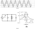
- the capacitance of the circuit directly affects the measured frequency characteristics of the complex impedance curve as shown in FIG 8 , which causes a phase drift over the operating frequency range. Consequently the criterion using 0 degree as the target is no longer valid.
- a coupled switch in the catheter handle as shown in Fig 11 provides a mechanism to effectively offset circuit capacitance.
- a precision calibration resistor is embedded in the handle. The coupling switch controls both the output switch and the calibration switch.
- the coupling switch 1 When the coupling switch 1 is disconnected, the coupling switch 2 is closed, and the precision calibration resistor is connected to the power output circuit, and the catheter coil is disconnected at the same time.
- the sampling circuit measures the precision calibration resistance with known resistance and the parasite capacitance of the circuit with unknown value.
- the coupling switch 1 When the coupling switch 1 is closed, the coupling switch 2 is disconnected, and the parasitic capacitance of the circuit is connected to the power output circuit together with the catheter coil. the DSP thus cancels the influence of the parasitic capacitance of the circuit with software.
- FIG 9 shows the impedance characteristics near the resonance caused by the inductance of the insulated heating coil and WPC.
- the control device can fine-tune the operating frequency of the radio frequency generator according to the test results generated by the WPC detecting device. By doing so the control device maintains the frequency operating point at the target control point 801 of the impedance of exemplary insulated heating coil as shown in FIG 8 , until the operating frequency is close to the initial operating frequency of the insulated heating coil.
- FIG. 10 is a diagram of the radio frequency thermal ablation system using the exemplary radio frequency generator circuitry.
- the components and details in the block diagram of the exemplary radio frequency generator are only one of the many possible implementations.
- the present invention is not limited to what has been particularly shown and described hereinabove. Variations on hardware or software may be made in the construction and relation of parts without departing from the scope of the invention described herein.
- the radio frequency thermal ablation system comprises a thermal ablation catheter and a radio frequency generator, the thermal ablation catheter comprises an inductive insulated heating coil.
- the radio frequency generator outputs radio frequency power to the insulated heating coil for heating.
- the inductance is designed to configure the operating frequency when detecting the parasitic capacitance between winding turns, and enhance the detecting sensitivity.
- the radio frequency thermal ablation system referred to in this embodiment is the radio frequency thermal ablation system of the first embodiment, and the technical details of the radio frequency thermal ablation system of the first embodiment may be applied.
- FIG. 11 is a process diagram of the control method of above-mentioned radio frequency thermal ablation system.
- the control method of the radio frequency thermal ablation system can specifically comprise the following steps: In step 1001, the radio frequency generator outputs the radio frequency power for heating to the insulated heating coil.
- the radio frequency generator monitors the change of WPC caused by the tubular organ wall approaching the insulated heating windings and/or the coagulation of body fluid during the heating process.
- the WPC can be calculated by monitoring the change of phase of voltage and current on the heating coil.
- the causes for the change in the complex impedance of the insulated heating coil of the thermal ablation catheter covered in this application comprise one or a combination of the following: 1 the wall of the tubular organ shrinks during thermal ablation, and moves towards the ablation catheter; 2 the body fluid outside the thermal ablation catheter gradually coagulates during the heating process.
- control method further comprises the following steps: in the pre-set operating frequency range, search and adjust the output frequency from said radio frequency generator, reduce the difference between said operating frequency and the resonant frequency of said complex impedance to be less than a pre-set threshold.
- the operating frequency range includes the frequency range in which the phase of the complex impedance of the insulated heating coil shifts from -90 degrees to 90 degrees.
- the parasitic impedance other than the insulated heating coil can be calibrated in advance during production or use, and then offset with software algorithm when monitor the WPC in real-time.
- the parasitic capacitance of the circuit calibrated during production is Cp, and Cp is in parallel with the insulated heating coil in the calculation model.
- I p ⁇ V o ⁇ 1 jwC p
- Vo output voltage
- Ip the current of the parasitic capacitance
- Io total output current
- the WPC after offsetting the influence of parasitic capacitance of the circuit can be calculated from the range of 90 degrees to -90 degrees according to the relationship between Ih and Vo.
- step 1003 the control device that controls the amount of radio frequency power output from said radio frequency generator to said heating coil according to the change of WPC (In other words, the shrink of the organ wall and/or body fluid coagulation can be deduced from the variation of the WPC).
- the control algorithm can adopt the common PID (proportional integral difference) control method and so on, and obtain the continuous and smooth control effect based on the treatment parameters like the shrinking degree of the organ wall and/or body fluid coagulation.
- the process described in above steps 1002-1003 on monitoring the change of complex impedance of the insulated heating coil, calculating WPC of the heating coil based on the detected change of the phase of the complex impedance, deducing the shrinking degree of the organ wall and/or body fluid coagulation, and controlling the radio frequency power output to the insulation heating coil can further comprise the following steps from i to iii:
- the inter-turn spacing of the heating coil satisfies the following condition: the resonance frequency caused by the inductance of said heating coil and expected WPC is within said frequency range, wherein said expected WPC is the inter-turn parasitic capacitance of said heating coil when the distance between blood vessel tissue and said thermal ablation catheter is within a pre-set range.
- resonant frequency can be pre-calibrated. Because of the corresponding relationship between WPC and resonant frequency, the resonant frequency can be indirectly used as a target for detection and control.
- FIG. 13 shows a test calibration process for an embodiment. After the calibration, the resonant frequency when the actual tubular organ is shrunk to the catheter is stored in memory as the target resonant frequency f r for use by the control device.
- FIG. 14 (A) is the case of the thermal ablation catheter with memory.
- the target output frequency of said radio frequency generator during treatment is the target resonant frequency fr stored during calibration, fr is the resonant frequency when the actual tubular organ is shrunk to the catheter.
- FIG. 14 (B) illustrates the process of the catheter without memory. A unified target frequency is used as the target frequency of the radio frequency generator during treatment.
- references in this application to an act performed according to an element mean the act is performed at least according to that element, which includes two cases: the act is performed in accordance with that element alone, and the act is performed in according to that element and other elements.
- 'Plural' means 2 or more than 2.
Landscapes
- Health & Medical Sciences (AREA)
- Surgery (AREA)
- Engineering & Computer Science (AREA)
- Life Sciences & Earth Sciences (AREA)
- Biomedical Technology (AREA)
- Otolaryngology (AREA)
- Nuclear Medicine, Radiotherapy & Molecular Imaging (AREA)
- Plasma & Fusion (AREA)
- Physics & Mathematics (AREA)
- Heart & Thoracic Surgery (AREA)
- Medical Informatics (AREA)
- Molecular Biology (AREA)
- Animal Behavior & Ethology (AREA)
- General Health & Medical Sciences (AREA)
- Public Health (AREA)
- Veterinary Medicine (AREA)
- Surgical Instruments (AREA)
Claims (6)
- Hochfrequenzwärmeablationssystem, umfassend:einen Wärmeablationskatheter, der eine induktive isolierte Heizspule (404) umfasst, wobei die Induktivität ausgelegt ist, die Betriebsfrequenz zu konfigurieren, wenn eine parasitäre Kapazität zwischen Wicklungswindungen erfasst wird, und die Erfassungsempfindlichkeit zu verbessern;einen Hochfrequenzgenerator, der Hochfrequenzleistung zum Erhitzen der Heizspule (404) zuführt;eine Erfassungsvorrichtung für parasitäre Wicklungskapazität, WPC (Winding Parasitic Capacitance), die die Änderung der WPC (602) zwischen den Isolierheizwicklungen überwacht, die durch Annäherung der Hohlorganwand (502) an die isolierten Heizwicklungen und/oder Koagulation von Körperflüssigkeit während des Erhitzungsprozesses verursacht wird, wobei die WPC-Erfassungsvorrichtung die Änderung von WPC (602) zwischen Heizspulenwicklungswindungen durch Erfassen der Spannungs- und Stromvektoren an der Heizspule (404) überwacht;eine Steuervorrichtung, die die Menge an Hochfrequenzleistung, die von dem Hochfrequenzgenerator an die Heizspule (404) ausgegeben wird, entsprechend der Änderung der WPC (602) zwischen den Wicklungen, die von der WPC-Erfassungsvorrichtung erfasst wird, steuert.
- Hochfrequenzwärmeablationssystem nach Anspruch 1, wobei die Steuervorrichtung weiter die parasitäre Kapazität zwischen den Heizspulenwicklungswindungen basierend auf der Vektorspannung und dem Vektorstrom der Heizspule (404) berechnet, die von der WPC-Erfassungsvorrichtung erfasst werden, und die Steuervorrichtung die Phase der kombinierten Impedanz der parasitären Kapazität zwischen den Heizspulenwicklungswindungen und der Spuleninduktivität extrahiert; wenn die Phase in einem voreingestellten Intervall ist, die Steuervorrichtung Ausgeben von Hochfrequenzleistung an die Heizspule (404) stoppt.
- Hochfrequenzwärmeablationssystem nach Anspruch 2, wobei die Ausgegebene Frequenz der Steuervorrichtung kontinuierlich einstellbar ist und die Steuervorrichtung die Frequenz der Hochfrequenzleistung, die von dem Hochfrequenzgenerator ausgegeben wird, in einem voreingestellten Frequenzbereich sucht und einstellt, sodass der Unterschied zwischen der Frequenz und der Resonanzfrequenz der komplexen Impedanz kleiner als ein voreingestellter Schwellenwert ist.
- Hochfrequenzwärmeablationssystem nach Anspruch 3, wobei der Betriebsfrequenzbereich den Frequenzbereich enthält, in dem die Phase der komplexen Impedanz der Heizspule -90 Grad bis 90 Grad verschoben ist, nachdem die parasitäre Kapazität aufgehoben worden ist.
- Hochfrequenzwärmeablationssystem nach Anspruch 3, wobei der Abstand zwischen Windungen der Heizspule (404) die folgende Bedingung erfüllt; die Resonanzfrequenz, die durch die Induktivität der Heizspule (404) und erwartete WPC (602) verursacht wird, ist innerhalb des Frequenzbereichs, wobei die erwartete WPC (602) die parasitäre Kapazität zwischen Windungen der Heizspule (404) ist, wenn der Abstand zwischen Blutgefäßgewebe und dem Wärmeablationskatheter innerhalb eines voreingestellten Bereichs ist.
- Hochfrequenzwärmeablationssystem nach Anspruch 5, weiter umfassend einen Flash-Speicher zum Speichern einer vorab kalibrierten Resonanzfrequenz, die als die Soll-Resonanzfrequenz für die Steuereinheit lesbar ist.
Applications Claiming Priority (3)
| Application Number | Priority Date | Filing Date | Title |
|---|---|---|---|
| CN201910611775 | 2019-07-08 | ||
| CN201910796082.8A CN111803204B (zh) | 2019-07-08 | 2019-09-16 | 射频热消融系统及其控制方法 |
| PCT/CN2020/093767 WO2021004196A1 (zh) | 2019-07-08 | 2020-06-01 | 射频热消融系统及其控制方法 |
Publications (4)
| Publication Number | Publication Date |
|---|---|
| EP3998032A1 EP3998032A1 (de) | 2022-05-18 |
| EP3998032A4 EP3998032A4 (de) | 2023-08-02 |
| EP3998032B1 true EP3998032B1 (de) | 2024-09-11 |
| EP3998032C0 EP3998032C0 (de) | 2024-09-11 |
Family
ID=72844516
Family Applications (1)
| Application Number | Title | Priority Date | Filing Date |
|---|---|---|---|
| EP20837136.9A Active EP3998032B1 (de) | 2019-07-08 | 2020-06-01 | Hochfrequenzwärmeablationssystem |
Country Status (5)
| Country | Link |
|---|---|
| EP (1) | EP3998032B1 (de) |
| CN (1) | CN111803204B (de) |
| ES (1) | ES2997247T3 (de) |
| HU (1) | HUE069340T2 (de) |
| WO (1) | WO2021004196A1 (de) |
Families Citing this family (5)
| Publication number | Priority date | Publication date | Assignee | Title |
|---|---|---|---|---|
| CN112244993B (zh) * | 2020-10-31 | 2022-03-15 | 杭州诺生医疗科技有限公司 | 射频消融仪 |
| CN114681042B (zh) * | 2020-12-28 | 2025-04-08 | 上海美杰医疗科技有限公司 | 射频消融测控系统 |
| CN113288410B (zh) * | 2021-07-08 | 2022-09-30 | 昆山雷盛医疗科技有限公司 | 腔体器官射频热消融系统 |
| CN114191708B (zh) * | 2021-12-15 | 2023-12-05 | 广东花至美容科技有限公司 | 美容仪射频输出功率控制方法、存储介质及电子设备 |
| CN115500934B (zh) * | 2022-11-23 | 2023-03-10 | 昆山雷盛医疗科技有限公司 | 射频热消融系统及其分段功率控制方法 |
Family Cites Families (19)
| Publication number | Priority date | Publication date | Assignee | Title |
|---|---|---|---|---|
| US4094320A (en) * | 1976-09-09 | 1978-06-13 | Valleylab, Inc. | Electrosurgical safety circuit and method of using same |
| US5152762A (en) * | 1990-11-16 | 1992-10-06 | Birtcher Medical Systems, Inc. | Current leakage control for electrosurgical generator |
| CA2106409A1 (en) * | 1991-11-08 | 1993-05-09 | Stuart D. Edwards | Radiofrequency ablation with phase sensitive power detection |
| GB0030929D0 (en) * | 2000-12-19 | 2001-01-31 | Inverness Medical Ltd | Analyte measurement |
| EP2662043A3 (de) | 2005-07-21 | 2016-03-16 | Covidien LP | Systeme und Verfahren zur Behandlung einer hohlen anatomischen Struktur |
| US20070179575A1 (en) | 2005-07-21 | 2007-08-02 | Esch Brady D | Thermal therapeutic catheter with location detection enhancement |
| WO2008023321A2 (en) * | 2006-08-22 | 2008-02-28 | Koninklijke Philips Electronics N.V. | Interventional device for rf ablation for use in rf fields |
| US10660690B2 (en) * | 2007-12-28 | 2020-05-26 | St. Jude Medical, Atrial Fibrillation Division, Inc. | System and method for measurement of an impedance using a catheter such as an ablation catheter |
| CN101862219B (zh) * | 2010-06-01 | 2011-12-21 | 谭伟 | 射频消融探头 |
| US9005192B2 (en) * | 2010-11-08 | 2015-04-14 | Biosense Webster (Israel) Ltd. | Simultaneous ablation by multiple electrodes |
| JP5259883B2 (ja) * | 2011-02-10 | 2013-08-07 | オリンパスメディカルシステムズ株式会社 | 高周波手術装置及び手術装置 |
| US9687289B2 (en) * | 2012-01-04 | 2017-06-27 | Biosense Webster (Israel) Ltd. | Contact assessment based on phase measurement |
| CN106659874B (zh) | 2014-03-26 | 2021-01-05 | 文科罗斯公司 | 静脉疾病治疗 |
| US10709492B2 (en) * | 2014-10-14 | 2020-07-14 | Biosense Webster (Israel) Ltd. | Effective parasitic capacitance minimization for micro ablation electrode |
| EP3093626B1 (de) * | 2015-05-12 | 2022-10-26 | Universita' degli studi di Brescia | System und verfahren zur messung von grössen |
| CN108366819B (zh) * | 2015-08-13 | 2021-05-28 | 柯惠股份公司 | 电动外科手术发生器及方法 |
| US20170202600A1 (en) | 2016-01-15 | 2017-07-20 | Cook Medical Technologies Llc | Medical device |
| US10555769B2 (en) * | 2016-02-22 | 2020-02-11 | Ethicon Llc | Flexible circuits for electrosurgical instrument |
| CN107317484B (zh) * | 2017-08-20 | 2023-12-12 | 昆山雷盛医疗科技有限公司 | 通用型有源手术器械功率发生器及其控制方法 |
-
2019
- 2019-09-16 CN CN201910796082.8A patent/CN111803204B/zh active Active
-
2020
- 2020-06-01 HU HUE20837136A patent/HUE069340T2/hu unknown
- 2020-06-01 EP EP20837136.9A patent/EP3998032B1/de active Active
- 2020-06-01 ES ES20837136T patent/ES2997247T3/es active Active
- 2020-06-01 WO PCT/CN2020/093767 patent/WO2021004196A1/zh not_active Ceased
Also Published As
| Publication number | Publication date |
|---|---|
| ES2997247T3 (en) | 2025-02-14 |
| HUE069340T2 (hu) | 2025-03-28 |
| CN111803204B (zh) | 2022-07-01 |
| CN111803204A (zh) | 2020-10-23 |
| EP3998032C0 (de) | 2024-09-11 |
| WO2021004196A1 (zh) | 2021-01-14 |
| EP3998032A1 (de) | 2022-05-18 |
| EP3998032A4 (de) | 2023-08-02 |
Similar Documents
| Publication | Publication Date | Title |
|---|---|---|
| EP3998032B1 (de) | Hochfrequenzwärmeablationssystem | |
| US12599433B2 (en) | Apparatus and method for intra-cardiac mapping and ablation | |
| US10016592B2 (en) | Control system and process for application of energy to airway walls and other mediums | |
| US8834388B2 (en) | Method and apparatus to regulate a tissue temperature | |
| US9119634B2 (en) | Apparatus and method for intra-cardiac mapping and ablation | |
| CN100396251C (zh) | 消融导管 | |
| EP1440665B1 (de) | Gerät zur therapeutischen Kauterisation von vorbestimmten Volumen biologischen Gewebes | |
| AU2008202047A1 (en) | Adjustable impedance electrosurgical electrodes | |
| US11389232B2 (en) | Apparatus and method for intra-cardiac mapping and ablation | |
| CN112384165A (zh) | 用于微波消融及在消融期间测量温度的系统 | |
| US20170202601A1 (en) | Medical device | |
| JP3611799B2 (ja) | 多目的アブレーション用バルーンカテーテル | |
| EP3192465A2 (de) | Medizinische vorrichtung | |
| WO2025160555A1 (en) | System, devices, and methods for delivering radiofrequency current for tissue perforation | |
| CN103347456B (zh) | 用于心律失常融除治疗的导管系统 | |
| EP3210558B1 (de) | Medizinische vorrichtung | |
| Ahmad et al. | On Electromagnetic Ablation of Biological Tissues: A Review |
Legal Events
| Date | Code | Title | Description |
|---|---|---|---|
| STAA | Information on the status of an ep patent application or granted ep patent |
Free format text: STATUS: THE INTERNATIONAL PUBLICATION HAS BEEN MADE |
|
| PUAI | Public reference made under article 153(3) epc to a published international application that has entered the european phase |
Free format text: ORIGINAL CODE: 0009012 |
|
| STAA | Information on the status of an ep patent application or granted ep patent |
Free format text: STATUS: REQUEST FOR EXAMINATION WAS MADE |
|
| 17P | Request for examination filed |
Effective date: 20220203 |
|
| AK | Designated contracting states |
Kind code of ref document: A1 Designated state(s): AL AT BE BG CH CY CZ DE DK EE ES FI FR GB GR HR HU IE IS IT LI LT LU LV MC MK MT NL NO PL PT RO RS SE SI SK SM TR |
|
| DAV | Request for validation of the european patent (deleted) | ||
| DAX | Request for extension of the european patent (deleted) | ||
| A4 | Supplementary search report drawn up and despatched |
Effective date: 20230705 |
|
| RIC1 | Information provided on ipc code assigned before grant |
Ipc: A61B 18/10 20060101ALI20230629BHEP Ipc: A61B 18/08 20060101ALI20230629BHEP Ipc: A61B 18/12 20060101AFI20230629BHEP |
|
| GRAP | Despatch of communication of intention to grant a patent |
Free format text: ORIGINAL CODE: EPIDOSNIGR1 |
|
| STAA | Information on the status of an ep patent application or granted ep patent |
Free format text: STATUS: GRANT OF PATENT IS INTENDED |
|
| INTG | Intention to grant announced |
Effective date: 20240424 |
|
| GRAS | Grant fee paid |
Free format text: ORIGINAL CODE: EPIDOSNIGR3 |
|
| GRAA | (expected) grant |
Free format text: ORIGINAL CODE: 0009210 |
|
| STAA | Information on the status of an ep patent application or granted ep patent |
Free format text: STATUS: THE PATENT HAS BEEN GRANTED |
|
| AK | Designated contracting states |
Kind code of ref document: B1 Designated state(s): AL AT BE BG CH CY CZ DE DK EE ES FI FR GB GR HR HU IE IS IT LI LT LU LV MC MK MT NL NO PL PT RO RS SE SI SK SM TR |
|
| REG | Reference to a national code |
Ref country code: GB Ref legal event code: FG4D |
|
| REG | Reference to a national code |
Ref country code: CH Ref legal event code: EP |
|
| REG | Reference to a national code |
Ref country code: DE Ref legal event code: R096 Ref document number: 602020037680 Country of ref document: DE |
|
| REG | Reference to a national code |
Ref country code: IE Ref legal event code: FG4D |
|
| U01 | Request for unitary effect filed |
Effective date: 20240925 |
|
| U07 | Unitary effect registered |
Designated state(s): AT BE BG DE DK EE FI FR IT LT LU LV MT NL PT RO SE SI Effective date: 20241018 |
|
| PG25 | Lapsed in a contracting state [announced via postgrant information from national office to epo] |
Ref country code: NO Free format text: LAPSE BECAUSE OF FAILURE TO SUBMIT A TRANSLATION OF THE DESCRIPTION OR TO PAY THE FEE WITHIN THE PRESCRIBED TIME-LIMIT Effective date: 20241211 |
|
| PG25 | Lapsed in a contracting state [announced via postgrant information from national office to epo] |
Ref country code: GR Free format text: LAPSE BECAUSE OF FAILURE TO SUBMIT A TRANSLATION OF THE DESCRIPTION OR TO PAY THE FEE WITHIN THE PRESCRIBED TIME-LIMIT Effective date: 20241212 |
|
| PG25 | Lapsed in a contracting state [announced via postgrant information from national office to epo] |
Ref country code: HR Free format text: LAPSE BECAUSE OF FAILURE TO SUBMIT A TRANSLATION OF THE DESCRIPTION OR TO PAY THE FEE WITHIN THE PRESCRIBED TIME-LIMIT Effective date: 20240911 |
|
| PG25 | Lapsed in a contracting state [announced via postgrant information from national office to epo] |
Ref country code: RS Free format text: LAPSE BECAUSE OF FAILURE TO SUBMIT A TRANSLATION OF THE DESCRIPTION OR TO PAY THE FEE WITHIN THE PRESCRIBED TIME-LIMIT Effective date: 20241211 |
|
| PG25 | Lapsed in a contracting state [announced via postgrant information from national office to epo] |
Ref country code: RS Free format text: LAPSE BECAUSE OF FAILURE TO SUBMIT A TRANSLATION OF THE DESCRIPTION OR TO PAY THE FEE WITHIN THE PRESCRIBED TIME-LIMIT Effective date: 20241211 Ref country code: NO Free format text: LAPSE BECAUSE OF FAILURE TO SUBMIT A TRANSLATION OF THE DESCRIPTION OR TO PAY THE FEE WITHIN THE PRESCRIBED TIME-LIMIT Effective date: 20241211 Ref country code: HR Free format text: LAPSE BECAUSE OF FAILURE TO SUBMIT A TRANSLATION OF THE DESCRIPTION OR TO PAY THE FEE WITHIN THE PRESCRIBED TIME-LIMIT Effective date: 20240911 Ref country code: GR Free format text: LAPSE BECAUSE OF FAILURE TO SUBMIT A TRANSLATION OF THE DESCRIPTION OR TO PAY THE FEE WITHIN THE PRESCRIBED TIME-LIMIT Effective date: 20241212 |
|
| REG | Reference to a national code |
Ref country code: ES Ref legal event code: FG2A Ref document number: 2997247 Country of ref document: ES Kind code of ref document: T3 Effective date: 20250214 |
|
| REG | Reference to a national code |
Ref country code: HU Ref legal event code: AG4A Ref document number: E069340 Country of ref document: HU |
|
| PG25 | Lapsed in a contracting state [announced via postgrant information from national office to epo] |
Ref country code: IS Free format text: LAPSE BECAUSE OF FAILURE TO SUBMIT A TRANSLATION OF THE DESCRIPTION OR TO PAY THE FEE WITHIN THE PRESCRIBED TIME-LIMIT Effective date: 20250111 |
|
| PG25 | Lapsed in a contracting state [announced via postgrant information from national office to epo] |
Ref country code: SM Free format text: LAPSE BECAUSE OF FAILURE TO SUBMIT A TRANSLATION OF THE DESCRIPTION OR TO PAY THE FEE WITHIN THE PRESCRIBED TIME-LIMIT Effective date: 20240911 |
|
| PG25 | Lapsed in a contracting state [announced via postgrant information from national office to epo] |
Ref country code: PL Free format text: LAPSE BECAUSE OF FAILURE TO SUBMIT A TRANSLATION OF THE DESCRIPTION OR TO PAY THE FEE WITHIN THE PRESCRIBED TIME-LIMIT Effective date: 20240911 Ref country code: CZ Free format text: LAPSE BECAUSE OF FAILURE TO SUBMIT A TRANSLATION OF THE DESCRIPTION OR TO PAY THE FEE WITHIN THE PRESCRIBED TIME-LIMIT Effective date: 20240911 |
|
| PG25 | Lapsed in a contracting state [announced via postgrant information from national office to epo] |
Ref country code: SK Free format text: LAPSE BECAUSE OF FAILURE TO SUBMIT A TRANSLATION OF THE DESCRIPTION OR TO PAY THE FEE WITHIN THE PRESCRIBED TIME-LIMIT Effective date: 20240911 |
|
| PGFP | Annual fee paid to national office [announced via postgrant information from national office to epo] |
Ref country code: HU Payment date: 20250620 Year of fee payment: 6 |
|
| PLBE | No opposition filed within time limit |
Free format text: ORIGINAL CODE: 0009261 |
|
| STAA | Information on the status of an ep patent application or granted ep patent |
Free format text: STATUS: NO OPPOSITION FILED WITHIN TIME LIMIT |
|
| PGFP | Annual fee paid to national office [announced via postgrant information from national office to epo] |
Ref country code: TR Payment date: 20250529 Year of fee payment: 6 |
|
| U20 | Renewal fee for the european patent with unitary effect paid |
Year of fee payment: 6 Effective date: 20250627 |
|
| 26N | No opposition filed |
Effective date: 20250612 |
|
| PGFP | Annual fee paid to national office [announced via postgrant information from national office to epo] |
Ref country code: ES Payment date: 20250731 Year of fee payment: 6 |
|
| REG | Reference to a national code |
Ref country code: CH Ref legal event code: H13 Free format text: ST27 STATUS EVENT CODE: U-0-0-H10-H13 (AS PROVIDED BY THE NATIONAL OFFICE) Effective date: 20260127 |
|
| PG25 | Lapsed in a contracting state [announced via postgrant information from national office to epo] |
Ref country code: MC Free format text: LAPSE BECAUSE OF FAILURE TO SUBMIT A TRANSLATION OF THE DESCRIPTION OR TO PAY THE FEE WITHIN THE PRESCRIBED TIME-LIMIT Effective date: 20240911 |
|
| GBPC | Gb: european patent ceased through non-payment of renewal fee |
Effective date: 20250601 |
|
| PG25 | Lapsed in a contracting state [announced via postgrant information from national office to epo] |
Ref country code: GB Free format text: LAPSE BECAUSE OF NON-PAYMENT OF DUE FEES Effective date: 20250601 |
|
| PG25 | Lapsed in a contracting state [announced via postgrant information from national office to epo] |
Ref country code: IE Free format text: LAPSE BECAUSE OF NON-PAYMENT OF DUE FEES Effective date: 20250601 |
|
| PG25 | Lapsed in a contracting state [announced via postgrant information from national office to epo] |
Ref country code: CH Free format text: LAPSE BECAUSE OF NON-PAYMENT OF DUE FEES Effective date: 20250630 |