EP3998192B1 - Structure de longeron d'aile - Google Patents
Structure de longeron d'aile Download PDFInfo
- Publication number
- EP3998192B1 EP3998192B1 EP21158246.5A EP21158246A EP3998192B1 EP 3998192 B1 EP3998192 B1 EP 3998192B1 EP 21158246 A EP21158246 A EP 21158246A EP 3998192 B1 EP3998192 B1 EP 3998192B1
- Authority
- EP
- European Patent Office
- Prior art keywords
- spar
- wing
- cap
- structure according
- connection portion
- Prior art date
- Legal status (The legal status is an assumption and is not a legal conclusion. Google has not performed a legal analysis and makes no representation as to the accuracy of the status listed.)
- Active
Links
Images

Classifications
-
- B—PERFORMING OPERATIONS; TRANSPORTING
- B64—AIRCRAFT; AVIATION; COSMONAUTICS
- B64C—AEROPLANES; HELICOPTERS
- B64C3/00—Wings
- B64C3/18—Spars; Ribs; Stringers
- B64C3/185—Spars
-
- B—PERFORMING OPERATIONS; TRANSPORTING
- B64—AIRCRAFT; AVIATION; COSMONAUTICS
- B64C—AEROPLANES; HELICOPTERS
- B64C1/00—Fuselages; Constructional features common to fuselages, wings, stabilising surfaces or the like
- B64C1/26—Attaching the wing or tail units or stabilising surfaces
Definitions
- the invention relates to a wing spar structure for an aircraft and an aircraft comprising such a wing spar structure.
- wingbox which is an integral part of the fuselage.
- the wingbox thus takes and transfers the wing bending loads.
- a wing box has a high structural integrity, but is one of the heaviest components of the aircraft.
- Smaller aircraft are usually constructed without a wing box by directly connecting the main spars of the left and right wings to one another. In such spar-to-spar connection, the bending moments from a load along the vertical Z-axis (leading to a moment about the longitudinal X-axis) are transferred through a force couple in lateral y-direction.
- a wing spar structure which allows to transfer bending moments between the wings without the use of a wing box, wherein the structure has a low weight, a high structural integrity, improved load distribution as well as advantages in assembly and maintenance.
- this object is achieved by a wing spar structure according to claim 1, in which a left spar is connected to the right spar by directly connecting the spar cap of the left wing to the spar cap of the right wing at a spar connection portion.
- a left spar is connected to the right spar by directly connecting the spar cap of the left wing to the spar cap of the right wing at a spar connection portion.
- the spar cap of the left spar and the spar cap of the right spar are connected via a bolt connection.
- a material with higher structural strength can be used for the bolts, whereas the spars may be designed with a lower structural strength.
- Bolts may be threaded to engage with a corresponding counter thread in one of the spar caps or with a threaded nut.
- press-fitted bolts or positively-locking form fitted bolts may be used.
- At least one bolt may be mounted such as to extend in a direction substantially parallel to the web portion.
- direct forces may be efficiently transferred between the cap portions through a positive-locking fit via the bolts.
- the bolt connection may comprise a plurality of bolts, preferably arranged in a symmetrical pattern to a vertical median plane of the right spar and/or the left spar such as to achieve symmetric fastening forces.
- each of the left and right spars has at least one spar cap.
- the web portion extends in a vertical direction of the aircraft.
- One upper spar cap may be provided at an upper portion of the web portion such as to extend orthogonally to the web portion in cross-section.
- two or more upper spar caps may be provided at the upper portion of the web portion, which both extend in parallel to one another and orthogonally to the web portion.
- the plurality of upper spar caps may be aligned in vertical direction, such as to be laminated on top of one another, or they may be aligned in horizontal direction (with equal vertical positions) such as to extend side-by-side.
- the upper spar caps may be glued or otherwise bonded together at their mating surfaces (in the case of vertical stacking) and/or at their adjacent longitudinal edges. By providing a plurality of upper spar caps, structural redundancy is achieved to further improve reliability and strength of the wing spar structure.
- one or more lower spar caps may be provided at a lower portion of the web portion such as to extend orthogonally to the web portion in cross-section. If two or more lower spar caps are provided, they may be configured as described above for the upper spar caps. If a spar has both upper and lower spar caps, a symmetric I-shape or double-T-shape can be implemented to take bending moments most efficiently.
- the wing spar structure further comprises at least one shear pin adapted to be fixed to a fuselage of the aircraft such as to transmit shear forces from the wing to the fuselage, said shear pin preferably being fixed to a wing root portion or a root rib attached to the left spar or the right spar.
- Shear pins allow to absorb shear forces originating from lift, for example, by transmitting the shear forces into the fuselage. Therefore, portions of the spars in a region within the fuselage receive lower or even no shear forces.
- the main spar web may have an additional fuselage attachment point, such that forces are transmitted from the wing to the fuselage through the shear pin and through the additional fuselage attachment point.
- two shear pins are associated to each wing, wherein one of the two shear pins is provided at a leading edge of the wing and the other one of the two shear pins is provided close to the trailing edge of the wing. In this way, torsion of the wing around the lateral axis as well as a moment around the vertical axis, such as from thrust in cruise-flight, for example, may efficiently and reliably be absorbed by the fuselage.
- a thickness of a portion of the spar cap adjacent to the spar connection portion may be larger, preferably more than 1.5 times larger, than a thickness of a portion of the spar cap at a distance from the spar connection portion. Therefore, the structural strength of the spar connection portion is enhanced to compensate for any material weakening due to the connection mean, such as through holes for receiving the bolts. Therefore, the weight of the wing spar structure may be reduced.
- the increase of the thickness towards the spar connection portion may be formed as a linear shape, in steps or as a curve.
- the spar caps of the right and the left wings may be connected at the connection portion in an overlapping manner.
- the spar cap of the right spar or the spar cap of the left spar may be formed in an U-shape (or fork shape) for receiving the spar cap of the respective other spar. In this manner, additional stabilization of the spars be mutual positive-locking fit may be achieved.
- the spar connection portion may be formed by a loop connection, which comprises a loop provided on at least one of the spars and a loop engaging structure, for example a pin or a bolt, arranged to pass through the loop.
- a simple loop connection is realized by a through hole within the spar cap of one of the spars and a loop engaging structure, for example a pin or a bolt, provided at the spar cap of the other one of the spars, such that the loop engaging structure engages with the loop.
- a loop connection can be constructed without weakening the material.
- fibers of the fiber material may extend in a loop shape at the spar connection portion around a central pin such as to form the loop.
- the web portion of the left spar and the web portion of the right spar have recesses arranges at their ends facing one another such as to jointly form a through hole.
- This through-hole may allow a cabin or cargo space to be arranged within the fuselage a position intersecting the spars, and saves weight.
- the web portion may be provided with light weight construction measures, preferably a recess portion without material.
- light weight construction measures preferably a recess portion without material.
- the wing spar structure may further comprise a second right spar and a second left spar, wherein the second right and left spars are connected to one another by connecting a spar cap of the left spar to a spar cap of the right spar at a second spar connection portion.
- the efficient spar connection according to the present invention may be applied to other spars of the wing structure to achieve the same effects.
- the spar cap of the left spar may be connected to the spar cap of the right spar in a fuselage region of the aircraft at the spar connection portion and wherein a height of the web portion in vertical direction may increase towards the spar connection portion.
- an aircraft comprising a wing spar structure according to any embodiment of the first aspect.
- an aircraft of the second aspect of the invention has a lightweight construction with a high structural strength, in particular in view of the direct transfer of bending moments between the spar caps of the left and right spars.
- the spars may be made of composite material, preferably fiber-reinforced material, most preferably carbon fiber reinforced material or glass fiber reinforced material.
- a wing may be any kind of airfoil, e.g. a conventional wing, a canard or the like.
- the invention may be adapted to any kinds of aircraft, including manned and unmanned aircraft, passenger and freight carriers.
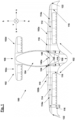
- an aircraft is generally denoted by reference numeral 100.
- the aircraft 100 comprises wings 102 and a fuselage 104.
- the aircraft 100 elongates from a front portion 106 to a rear portion 108 in a horizontal direction h (X-axis or longitudinal axis), which is equivalent to a heading direction h.
- the wings 102 protrude, viewed from the rear 108 to the front 106, in a lateral direction s towards left and right, respectively.
- the aircraft 100 comprises a right wing 102a and a left wing 102b arranged at the rear 108.
- a right canard 102c and a left canard 102d are arranged.
- Both the wings 102a, 102b and the canards 102c, 102d may be equipped with a wing spar structure 110.
- a wing spar structure 110 is shown for the right wing 102a and the left wing 102b only. This is indicated by dashed lines.
- the wing spar structure 110 may be adapted to any other type of wing, e.g. canard 102c, 102d.
- the invention is not limited to this embodiment.
- the aircraft 100 may have a standard configuration with a wing and a tailplane, or a blended wing body configuration.
- the wing spar structure 110 comprises a right spar 112 and a left spar 114 associated to the right wing 102a and the left wing 102b, respectively, in a well know manner.
- Substantially orthogonal to the spar 112, 114 a plurality of ribs 116 protrude from the spar 112, 114, adjusted to a width 117 of the wing 102a, 102b.
- the root rib 118 is mounted to the fuselage 104 with at least one shear pin 120.
- the shear pin 120 is adapted to transfer shear forces from the spar 112, 114 into the fuselage 104.
- the spars 112, 114 have substantially the same length in the lateral direction s as the wing from a peripheral portion 122 to a fuselage region 124.
- the length of the right wing 102a and the left wing 102b and a lateral size of the fuselage 104 form a wingspan.
- the wingspan may be more than 10 meter.
- the wings spar structure 110 may further comprise a second right spar 112a and a second left spar 114a, connected by connecting a spar cap 32 (not shown) of the left wing 102b to a spar cap 32 (not shown) of the right wing 102a at a second spar connection portion 140a.
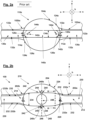
- Figure 2a shows a wing spar structure 110z according to the prior art in a cross sectional view from a front towards a rear of an aircraft. Analogous parts are provided with the same reference numerals as in Figure 1 , but followed with a z.
- the wing spar structure 110z comprises a right spar 112z associated to a right wing 102az and a left spar 114z associated to a left wing 102bz.
- the right wing 112z and the left wing 114z are mounted to the fuselage 104z in a fuselage region 124z.
- Each spar 112z, 114z projects into the fuselage portion and ends with a spar end portion 126z within the fuselage region 124z.
- a shear pin 120z is provided, which is fixed to the fuselage 104z such as to transmit shear forces from the wing to the fuselage 104z.
- Each spar 112z, 114z has a web portion 130z extending in a substantial vertical direction v, which is orthogonal to the horizontal direction h and the lateral direction s. On each end of the web portion, a spar cap 132z is provided.
- a height 134z of the web portion 130z of the spars 112z, 114z is substantially constant from a peripheral portion 122z to a spar connection portion 140z within the fuselage 104z.
- the right spar 112z and the left spar 114z are connected in an overlapping manner.
- the web portion 130z of right spar 112z is overlapped by the web portion 130z of the left spar 114z, which is indicated by a dashed line.
- the web portion 130z of the right spar 112z and web portions 130z of the left spar 114z are connected with a bolt connection 142z via a bolt 144z extending in horizontal direction h.
- FIG. 2b an embodiment of a wing spar structure 210 according to the invention is shown in Figure 2b .
- Analogous parts are provided with the same reference numerals as in Figure 1 and Figure 2a but increased by 100 and without the following z.
- the wing spar structure 210 comprises a left wing 202a and a right wing 202b. To the left wing 202a a left spar 214 and to the right wing 202b a right spar 212 is associated. Each spar 212, 214 has a web portion 230 and at least one spar cap 232 extending substantially orthogonal from the web portion 230 in horizontal direction h.
- a spar cap 232a of the right spar 212 and a spar cap 232b of the left spar 214 are connected at a spar connection portion 240 via bolt connection 242.
- the right spar cap 232a and the left spar cap 232b are provided with a hole, e.g., drilled or formed with split layers.
- the bolt 244 may be a bolt secured with a spring at its end, a screw-nut connection, a press fitted bolt, a friction welding bolt, a bolt-in-bolt connection, a pin-in-pin connection or the like.
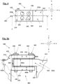
- the spar caps 232a, 232b are provided with an internal thread and the bolt 244 is provided with an external thread. Variants of such bolt connection 242 according to the present invention will by described further below with reference to the Figures 4, 5a and 5b .
- a height 234 of the web portion 230 increases towards the spar connection portion 240.
- a through-hole portion 248, for reducing weight is provided, which may for example be formed by recesses provided in the web portions 230 of the left and right spars, respectively, such as to face on another.
- a shear pin 220 is preferably provided, which is fixed to the fuselage 204 such as to transmit shear forces from the wing to the fuselage 104.
- two shear pins are associated to each wing, wherein one of the two shear pins is provided at a leading edge of the wing and the other one of the two shear pins is provided at the trailing edge of the wing.
- a wing spar structure 310 ( Figure 2c ) is provided with additional light weight construction measures 350 formed by a plurality of recess portions 350 arranged on a lateral axis 352 with a central through-hole portion 348, for example.
- the wing spar structure 310 corresponds mainly with the wing spar structure 210 as shown in Figure 2b . Analogous parts are provided with the same reference numerals as in Figure 2b , but increased by 100 (e.g. spar connection portion 240 corresponds to spar connection portion 340). Further, the wing spar structure 310 is only described in the following insofar as it differs from the wing spar structure of Figure 2b .
- shear pins 320 are provided.
- the shear pins 320 may be a bolt secured with a spring or a linkage system.
- Two shear pins are preferably associated to each wing, one at a leading edge of the wing and the other one at the trailing edge of the wing, such as to efficiently transfer torsion of the wing around the lateral axis as well as a moment around the vertical axis from the wing to the fuselage.
- a cross section of the right spar 212 cut along an axis III-III viewed as indicated in Figure 2b is provided in Figure 3 .
- the right spar 212 may be formed with an essentially I-shaped cross section, but could also be formed with an O-shaped cross section (box-spar).
- the spar has a web portion 230 elongating in substantially vertical direction. Said web portion 230 assumes a height 234 in vertical direction v and web width 260 in horizontal direction h.
- the web width 260 may be essentially constant.
- two spar caps 232 are arranged in an essentially horizontal direction h.
- the spar caps 232 have a spar cap width 262 in horizontal direction and a thickness 264 in vertical direction.
- the thickness 264 may increase at the spar connection portion 240.
- the spar cap width 262 may be scaled with respect to a width of the wing 117 (see Figure 1 ), but usually the spar cap width 262 is essentially constant.
- the I-shaped cross section of the spar is symmetrical to a vertical median plane 266, but can have different spar cap cross-sections depending on the loading conditions.
- the web portion 230 may be arranged essentially in the center of the spar caps 232.
- other embodiments are also feasibly, e.g. a C-shaped cross section, a non-symmetrical I-shape or a rectangular shape.
- the spar caps 232 and the web portion 230 are integrally connected with each other.
- the spar caps 232 are first produced, e.g. by laying a plurality of fiber reinforced layers into a form until the desired spar cap height 264 and spar cap width 262 are achieved.
- the spar cap 232 is treated for example with a resin material in order to join different layers, to be stabilized and to be protected of environmental influences.
- the web portion 230 is manufactured in a similar way. As the web portion 230 is manufactured independently from the spar caps 232, it can assume any form, e.g. an increasing height 234.
- the web portion 230 and the spar caps 232 are joined, e.g. via a glue connection and with support of another form or by using a not fully dried, for example dried overnight, resin material as joining material.
- the spars 212, 214 are manufactured, more components are added, e.g. wing membranes, flaps, light system, fuel conduct system if available and the like, until the wing 202a, 202b is fully assembled.
- the right wing 202a and the left wing 202b are supplied to a fuselage 204 and the at least one spar 212, 214 are introduced into the fuselage 204 at a fuselage region 224.
- the wings 202a, 202b are connected to the fuselage 204 at the spar connection portion 240.
- the right spar 212 and the left spar 214 may have two spar caps 232.
- Each left spar cap 232b is connected to the respective right spar cap 232a and they form an upper connection portion 240a and a lower spar connection portion 240b, respectively.
- the upper spar connection portion 240a and the lower spar connection portion 240b may be formed in a similar manner. Nevertheless, it is obvious for those skilled in the art, that the each spar connection portion may be formed in a different manner.
- the at least one right spar cap 232a of the right spar 212 and the at least one left spar cap 232b of the left spar 214 are connected to each other in an overlapping manner.
- the right spar cap 232a and the left spar cap 232b are connected via a bolt connection 242.
- the bolt connection may comprise a plurality of bolts 244. At least one bolt 244 may be arranged in a substantially vertical direction v, which is substantially parallel to the direction of the web portion 230. The plurality of bolts 242 may be arranged in a symmetrical pattern with respect to the vertical median plane 266 of the right spar 212 and the left spar 214.
- a spar connection portion 440 according to a first variant is shown in Figure 5a in a cross sectional view according to a line V-V in Figure 4 .
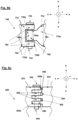
- a right spar cap 432a of a right spar 412 and a left spar cap 432b of a left spar 414 are connected with a bolt connection 442, wherein a bolt 444 is arranged in a direction substantially parallel to a web portion 430, i.e. in vertical direction v.
- the left spar cap 432b is formed in a U-shape 470, wherein a first leg 472 is above as second leg 474 and the U-shape 470 is open in lateral direction.
- An opening 476 of the U-shape 470, or fork, is adapted to receive the right spar cap 432a, or a tongue of the right spar 412.
- the left spar cap 432b may form a tongue and the left spar may form a fork.
- web portion 430 may have a recess 480 which allows the left and right spar caps 432a, 432b to overlap each other.
- Each spar cap 432 may have a thickness 464 which increases towards the spar connection portion 440.
- a thickness 464a of the spar cap 432a or tongue or right spar 412 may be thicker than a thickness 464b of each of the first and second legs 472, 474.
- the sum of the thicknesses 464b of the first and second legs 472, 474 may be equal to or larger than a thickness 464c of left spar cap 432b at a distance from the spar connection portion 440.
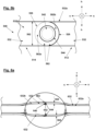
- a left spar cap 532b of a left spar 514 may form a single left spar cap loop 582b
- a right spar cap 532a of a right spar 512 may form a single right spar cap loop 582a, respectively.
- Said spar cap loops 582a, 582b may be manufactured with split layers of a multilayer material and may be integrally formed by the respective spar caps 532a, 532b.
- a width 562 of the spar caps may be constant as shown in Figure 5b , but may alternatively increase towards the spar connection portion 540.
- the spar cap loops 582a, 582b are axially aligned and receive a bolt 544 in vertical direction for connecting the spar caps 532 and forming a bolt connection 542.
- Bolt 544 may be a threaded bolt engaging a counter thread within one or both spar caps or within a threaded nut.
- the bolt may comprise a first hollow pin which receives a second pin, such as to have structural redundancy.
- Figure 6a shows a third variant of a spar connection portion.
- Each spar cap 632 is provided with a loop 682.
- a right spar cap 632a and a left spar cap 632b are connected via the loops 682 with a bolt connection 642 at a connection portion 640. Therefore, the loop 682 of the right spar cap 632a and the loop 682 of the left spar cap 632b are arranged in an aligned, overlapping manner.
- a bolt 644 is arranged, in particular essentially in heading direction h.
- a thickness 664 of the right spar cap 632a and the left spar cap 632b may increase towards the spar connection portion 640 such as to secure sufficient material for providing the bolt connection 642.
- FIG. 6b and Figure 6c show different embodiments of a bolt connection 742 and 842, which may both be used for the third variant of the spar connection portion 640 as shown in Figure 6a .
- Each bolt connection 742, 842 comprises a bolt 744, 844.
- Said bolt 744, 844 may be arranged in a direction substantially equal to the heading direction h.
- a spar cap 732b is provided with a clevis 784 at a spar end portion 726b. Said clevis 784 receives a spar end portion 726a of another spar cap 732a, formed as a lug 786. For receiving the bolt 744, each spar cap 732a, 732b is formed with a spar cap loop 782 at the spar end portion 726a, 726b.
- a width 764a, 764b in heading direction h of at least one of the spar caps 732 adjacent to a spar connection portion 740 may differ from a width 764 in heading direction h at a distance from the spar connection portion 740.
- the right spar cap 732a may be tapered towards the spar connection portion 740.
- a spar end portion 826a, 826b of each spar cap 832 may be formed in a fork shape comprising a plurality of fork teeth 890 and a plurality of gaps 892 between the fork teeth 890.
- the gaps 892 may have bottom portions 894 and side portions 896 adapted to the shape of the fork teeth 890 to allow engagement of the fork teeth 890 within the gaps 892.
- the spar caps 832 are connected with a bolt 844 extending in heading direction h through axially aligned holes 882 provided in each of the fork teeth 890.
Landscapes
- Engineering & Computer Science (AREA)
- Mechanical Engineering (AREA)
- Aviation & Aerospace Engineering (AREA)
- Connection Of Plates (AREA)
Claims (13)
- Structure de longeron d'aile (110, 210, 310) pour un avion (100), comprenant une aile gauche et une aile droite, dans laquelle un longeron gauche (114, 214, 414, 514, 614) est associé à l'aile gauche (102b, 202b) de l'avion et un longeron droit (112, 212, 412, 512, 612) est associé à l'aile droite (102a, 202a) de l'avion,dans laquelle chaque longeron (112, 114, 212, 214, 412, 414, 512, 514, 612, 614) a une partie âme (230, 430, 630) et au moins une semelle de longeron (232, 232a, 232b, 432, 432a, 432b, 532, 532a, 532b, 632, 632a, 632b), dans laquelle, dans une section transversale orthogonale à l'axe longitudinal des longerons, la partie âme s'étend dans une direction sensiblement verticale (V) et la au moins une semelle de longeron (232, 232a, 232b, 432, 432a, 432b, 532, 532a, 532b, 632, 632a, 632b) s'étend dans une direction sensiblement orthogonale à la partie âme (230, 430, 830),dans laquelle le longeron gauche (114, 214, 414, 514, 614) est relié au longeron droit (112, 212, 412, 512, 612) par liaison de la semelle de longeron (232b, 432b, 532b, 632b) du longeron gauche à la semelle de longeron (232a, 432a, 532a, 632a) du longeron droit au niveau d'une partie de liaison de longerons (140, 240, 240a, 240b, 340, 440, 540, 640),caractérisée en ce que la semelle de longeron (232b, 432b, 532b, 632b) du longeron gauche (114, 214, 414, 514, 614) et la semelle de longeron (232a, 432a, 532a, 632a) du longeron droit (112, 212, 412, 512, 612) sont reliées directement via une liaison par boulons (242, 442, 542, 642), et en ce qu'elle comprend en outre au moins une broche de cisaillement adaptée pour être fixée à un fuselage de l'avion de manière à transmettre les forces de cisaillement de la structure de longeron d'aile au fuselage, ladite broche de cisaillement étant de préférence fixée à une partie d'emplanture d'aile ou à une nervure d'emplanture fixée au longeron gauche ou au longeron droit.
- Structure de longeron d'aile selon la revendication 1,
dans laquelle au moins un boulon (244, 444, 544, 684) est disposé dans une direction sensiblement parallèle à la partie âme (230, 430, 630). - Structure de longeron d'aile selon la revendication 1 ou 2,
dans laquelle la liaison par boulons (242, 442, 542, 642) comprend une pluralité de boulons (244, 444, 544, 684), disposés de préférence selon un motif symétrique par rapport à un plan médian vertical (266) du longeron droit (112, 212, 412, 512, 612) et/ou du longeron gauche (114, 214, 414, 514, 614). - Structure de longeron d'aile selon l'une quelconque des revendications 1 à 3,
dans laquelle, dans au moins l'un parmi le longeron gauche et le longeron droit, une épaisseur (464, 464a, 664, 664a, 664b) d'une partie de la semelle de longeron adjacente à la partie de liaison de longerons (140, 240, 240a, 240b, 340, 440, 540, 640) est plus grande, de préférence plus de 1,5 fois plus grande, qu'une épaisseur (464) d'une partie de la semelle de longeron à une distance de la partie de liaison de longerons. - Structure de longeron d'aile selon l'une quelconque des revendications 1 à 4,
dans laquelle la semelle de longeron (232a, 432a, 532a, 632a) du longeron droit (112, 212, 412, 512, 612) ou la semelle de longeron (232b, 432b, 532b, 632b) du longeron gauche (114, 214, 414, 514, 614) est formée en une forme en U (470) pour recevoir la semelle de longeron (232, 232a, 232b, 432, 432a, 432b, 532, 532a, 532b, 632, 632a, 632b) de l'autre longeron respectif (112, 114, 212, 214, 412, 414, 512, 514, 612, 614). - Structure de longeron d'aile selon la revendication 5,
dans laquelle une branche (472) de la forme en U (470) est disposée au-dessus d'une autre branche (474) de la forme en U dans la direction verticale (v). - Structure de longeron d'aile selon l'une quelconque des revendications 1 à 6,
dans laquelle la partie de liaison de longerons est formée par une liaison en boucle comprenant une boucle (582, 582a, 582b, 682) disposée sur au moins l'un des longerons et une structure d'engagement de boucle, par exemple une broche ou un boulon, disposée pour traverser la boucle. - Structure de longeron d'aile selon la revendication 7,
dans laquelle les longerons gauche et droit sont formés à partir d'un matériau fibreux et dans laquelle, au niveau de la partie de liaison de longerons, les fibres du matériau fibreux s'étendent en forme de boucle de manière à former la boucle (582, 582a, 582b, 682). - Structure de longeron d'aile selon l'une quelconque des revendications 1 à 8,
dans laquelle la partie âme (230, 430, 630) du longeron gauche et la partie âme du longeron droit ont des évidements disposés à leurs extrémités tournées l'une vers l'autre de manière à former conjointement un trou traversant (248, 348). - Structure de longeron d'aile selon l'une quelconque des revendications 1 à 9,
dans laquelle la partie âme (230, 430, 630) est munie de mesures de construction légères (350), de préférence une partie évidée sans matériau. - Structure de longeron d'aile selon l'une quelconque des revendications 1 à 10,
comprenant en outre un deuxième longeron droit (112a) et un deuxième longeron gauche (114a), dans laquelle les deuxièmes longerons droit et gauche (112a, 114a) sont reliés l'un à l'autre par liaison d'une semelle de longeron (32) du deuxième longeron gauche à une semelle de longeron du deuxième longeron droit au niveau d'une deuxième partie de liaison de longerons (140a). - Structure de longeron d'aile (110, 210, 310) selon l'une quelconque des revendications 1 à 11,dans laquelle la semelle de longeron (232b) du longeron gauche (114, 214, 414, 514, 614) est reliée à la semelle de longeron (232a) du longeron droit (112, 212, 412, 512, 612), lorsqu'ils sont utilisés, dans une région de fuselage (124, 224, 324) de l'avion, au niveau de la partie de liaison de longerons (140, 240, 240a, 240b, 340, 440, 540, 640),dans laquelle une hauteur (234) de la partie âme (230, 430, 630) dans la direction verticale (v) augmente vers la partie de liaison de longerons (140, 240, 240a, 240b, 340, 440, 540, 640).
- Avion comprenant une structure de longeron d'aile selon au moins l'une des revendications 1 à 12.
Priority Applications (1)
| Application Number | Priority Date | Filing Date | Title |
|---|---|---|---|
| EP21158246.5A EP3998192B1 (fr) | 2021-02-19 | 2021-02-19 | Structure de longeron d'aile |
Applications Claiming Priority (1)
| Application Number | Priority Date | Filing Date | Title |
|---|---|---|---|
| EP21158246.5A EP3998192B1 (fr) | 2021-02-19 | 2021-02-19 | Structure de longeron d'aile |
Publications (2)
| Publication Number | Publication Date |
|---|---|
| EP3998192A1 EP3998192A1 (fr) | 2022-05-18 |
| EP3998192B1 true EP3998192B1 (fr) | 2024-03-20 |
Family
ID=74672235
Family Applications (1)
| Application Number | Title | Priority Date | Filing Date |
|---|---|---|---|
| EP21158246.5A Active EP3998192B1 (fr) | 2021-02-19 | 2021-02-19 | Structure de longeron d'aile |
Country Status (1)
| Country | Link |
|---|---|
| EP (1) | EP3998192B1 (fr) |
Families Citing this family (1)
| Publication number | Priority date | Publication date | Assignee | Title |
|---|---|---|---|---|
| CN115626310B (zh) * | 2022-09-19 | 2025-07-04 | 航天时代飞鹏有限公司 | 一种货运无人机翼身连接结构及连接方法 |
Citations (1)
| Publication number | Priority date | Publication date | Assignee | Title |
|---|---|---|---|---|
| US3519228A (en) * | 1967-09-29 | 1970-07-07 | Dow Chemical Co | Airfoil structure |
Family Cites Families (9)
| Publication number | Priority date | Publication date | Assignee | Title |
|---|---|---|---|---|
| FR543443A (fr) * | 1921-11-10 | 1922-09-02 | Mode d'assemblage des longerons dans les voilures d'aéroplanes | |
| US3159228A (en) * | 1961-02-27 | 1964-12-01 | Mcculloch Corp | Dynamic seal for air suspension vehicle |
| GB1348826A (en) * | 1972-07-03 | 1974-03-27 | British Aircraft Corp Ltd | Aircraft |
| US4535958A (en) * | 1982-12-13 | 1985-08-20 | Hutchison Gary A | Aluminum composite spar wing structure and method of assembly |
| FR2576279A1 (fr) * | 1985-01-21 | 1986-07-25 | Metz Jean Francois | Avion leger comportant deux demi-ailes en materiaux composites |
| GB2435457B (en) * | 2006-02-28 | 2011-03-09 | Hal Errikos Calamvokis | Aircraft wings and their assembly |
| JP4657191B2 (ja) * | 2006-11-02 | 2011-03-23 | 本田技研工業株式会社 | 飛行機の主翼構造 |
| WO2011071939A2 (fr) * | 2009-12-07 | 2011-06-16 | Global Aerosystems, Llc | Joint de montage de longeron d'aile |
| RU2481243C1 (ru) * | 2012-01-31 | 2013-05-10 | Закрытое акционерное общество "Гражданские самолеты Сухого" | Крыло самолета и узел стыка его консолей |
-
2021
- 2021-02-19 EP EP21158246.5A patent/EP3998192B1/fr active Active
Patent Citations (1)
| Publication number | Priority date | Publication date | Assignee | Title |
|---|---|---|---|---|
| US3519228A (en) * | 1967-09-29 | 1970-07-07 | Dow Chemical Co | Airfoil structure |
Also Published As
| Publication number | Publication date |
|---|---|
| EP3998192A1 (fr) | 2022-05-18 |
Similar Documents
| Publication | Publication Date | Title |
|---|---|---|
| US9580164B2 (en) | Apparatus and methods for joining aircraft composite structures | |
| EP1999013B1 (fr) | Element d'aeronef | |
| US9751608B2 (en) | Composite material structure, and aircraft wing and aircraft fuselage provided therewith | |
| US9108718B2 (en) | Composite-material structure and aircraft main wing and aircraft fuselage provided with the same | |
| US9145197B2 (en) | Vertically integrated stringers | |
| KR101914671B1 (ko) | 조인트 | |
| US20120234978A1 (en) | Load transfer devices at a stringer run-out | |
| US10875625B2 (en) | Co-cured spar and stringer center wing box | |
| JP2012162147A5 (fr) | ||
| US20160325820A1 (en) | Structural component | |
| US12077289B2 (en) | Aircraft assembly having an integral spar-cover | |
| EP3998192B1 (fr) | Structure de longeron d'aile | |
| US8118260B2 (en) | Fitting for trimming a horizontal stabilizer of an aircraft | |
| EP4282751B1 (fr) | Système d'introduction de charge et procédé de fabrication d'un système d'introduction de charge |
Legal Events
| Date | Code | Title | Description |
|---|---|---|---|
| PUAI | Public reference made under article 153(3) epc to a published international application that has entered the european phase |
Free format text: ORIGINAL CODE: 0009012 |
|
| STAA | Information on the status of an ep patent application or granted ep patent |
Free format text: STATUS: THE APPLICATION HAS BEEN PUBLISHED |
|
| AK | Designated contracting states |
Kind code of ref document: A1 Designated state(s): AL AT BE BG CH CY CZ DE DK EE ES FI FR GB GR HR HU IE IS IT LI LT LU LV MC MK MT NL NO PL PT RO RS SE SI SK SM TR |
|
| STAA | Information on the status of an ep patent application or granted ep patent |
Free format text: STATUS: REQUEST FOR EXAMINATION WAS MADE |
|
| 17P | Request for examination filed |
Effective date: 20221117 |
|
| RBV | Designated contracting states (corrected) |
Designated state(s): AL AT BE BG CH CY CZ DE DK EE ES FI FR GB GR HR HU IE IS IT LI LT LU LV MC MK MT NL NO PL PT RO RS SE SI SK SM TR |
|
| GRAP | Despatch of communication of intention to grant a patent |
Free format text: ORIGINAL CODE: EPIDOSNIGR1 |
|
| STAA | Information on the status of an ep patent application or granted ep patent |
Free format text: STATUS: GRANT OF PATENT IS INTENDED |
|
| INTG | Intention to grant announced |
Effective date: 20230929 |
|
| GRAS | Grant fee paid |
Free format text: ORIGINAL CODE: EPIDOSNIGR3 |
|
| GRAA | (expected) grant |
Free format text: ORIGINAL CODE: 0009210 |
|
| STAA | Information on the status of an ep patent application or granted ep patent |
Free format text: STATUS: THE PATENT HAS BEEN GRANTED |
|
| AK | Designated contracting states |
Kind code of ref document: B1 Designated state(s): AL AT BE BG CH CY CZ DE DK EE ES FI FR GB GR HR HU IE IS IT LI LT LU LV MC MK MT NL NO PL PT RO RS SE SI SK SM TR |
|
| REG | Reference to a national code |
Ref country code: GB Ref legal event code: FG4D |
|
| REG | Reference to a national code |
Ref country code: CH Ref legal event code: EP |
|
| REG | Reference to a national code |
Ref country code: IE Ref legal event code: FG4D |
|
| REG | Reference to a national code |
Ref country code: DE Ref legal event code: R096 Ref document number: 602021010543 Country of ref document: DE |
|
| REG | Reference to a national code |
Ref country code: NL Ref legal event code: FP |
|
| PG25 | Lapsed in a contracting state [announced via postgrant information from national office to epo] |
Ref country code: LT Free format text: LAPSE BECAUSE OF FAILURE TO SUBMIT A TRANSLATION OF THE DESCRIPTION OR TO PAY THE FEE WITHIN THE PRESCRIBED TIME-LIMIT Effective date: 20240320 |
|
| REG | Reference to a national code |
Ref country code: LT Ref legal event code: MG9D |
|
| PG25 | Lapsed in a contracting state [announced via postgrant information from national office to epo] |
Ref country code: GR Free format text: LAPSE BECAUSE OF FAILURE TO SUBMIT A TRANSLATION OF THE DESCRIPTION OR TO PAY THE FEE WITHIN THE PRESCRIBED TIME-LIMIT Effective date: 20240621 |
|
| PG25 | Lapsed in a contracting state [announced via postgrant information from national office to epo] |
Ref country code: RS Free format text: LAPSE BECAUSE OF FAILURE TO SUBMIT A TRANSLATION OF THE DESCRIPTION OR TO PAY THE FEE WITHIN THE PRESCRIBED TIME-LIMIT Effective date: 20240620 Ref country code: HR Free format text: LAPSE BECAUSE OF FAILURE TO SUBMIT A TRANSLATION OF THE DESCRIPTION OR TO PAY THE FEE WITHIN THE PRESCRIBED TIME-LIMIT Effective date: 20240320 |
|
| PG25 | Lapsed in a contracting state [announced via postgrant information from national office to epo] |
Ref country code: RS Free format text: LAPSE BECAUSE OF FAILURE TO SUBMIT A TRANSLATION OF THE DESCRIPTION OR TO PAY THE FEE WITHIN THE PRESCRIBED TIME-LIMIT Effective date: 20240620 Ref country code: NO Free format text: LAPSE BECAUSE OF FAILURE TO SUBMIT A TRANSLATION OF THE DESCRIPTION OR TO PAY THE FEE WITHIN THE PRESCRIBED TIME-LIMIT Effective date: 20240620 Ref country code: LT Free format text: LAPSE BECAUSE OF FAILURE TO SUBMIT A TRANSLATION OF THE DESCRIPTION OR TO PAY THE FEE WITHIN THE PRESCRIBED TIME-LIMIT Effective date: 20240320 Ref country code: HR Free format text: LAPSE BECAUSE OF FAILURE TO SUBMIT A TRANSLATION OF THE DESCRIPTION OR TO PAY THE FEE WITHIN THE PRESCRIBED TIME-LIMIT Effective date: 20240320 Ref country code: GR Free format text: LAPSE BECAUSE OF FAILURE TO SUBMIT A TRANSLATION OF THE DESCRIPTION OR TO PAY THE FEE WITHIN THE PRESCRIBED TIME-LIMIT Effective date: 20240621 Ref country code: FI Free format text: LAPSE BECAUSE OF FAILURE TO SUBMIT A TRANSLATION OF THE DESCRIPTION OR TO PAY THE FEE WITHIN THE PRESCRIBED TIME-LIMIT Effective date: 20240320 Ref country code: BG Free format text: LAPSE BECAUSE OF FAILURE TO SUBMIT A TRANSLATION OF THE DESCRIPTION OR TO PAY THE FEE WITHIN THE PRESCRIBED TIME-LIMIT Effective date: 20240320 |
|
| REG | Reference to a national code |
Ref country code: AT Ref legal event code: MK05 Ref document number: 1667615 Country of ref document: AT Kind code of ref document: T Effective date: 20240320 |
|
| PG25 | Lapsed in a contracting state [announced via postgrant information from national office to epo] |
Ref country code: SE Free format text: LAPSE BECAUSE OF FAILURE TO SUBMIT A TRANSLATION OF THE DESCRIPTION OR TO PAY THE FEE WITHIN THE PRESCRIBED TIME-LIMIT Effective date: 20240320 Ref country code: LV Free format text: LAPSE BECAUSE OF FAILURE TO SUBMIT A TRANSLATION OF THE DESCRIPTION OR TO PAY THE FEE WITHIN THE PRESCRIBED TIME-LIMIT Effective date: 20240320 |
|
| P01 | Opt-out of the competence of the unified patent court (upc) registered |
Free format text: CASE NUMBER: APP_44525/2024 Effective date: 20240731 |
|
| PG25 | Lapsed in a contracting state [announced via postgrant information from national office to epo] |
Ref country code: IS Free format text: LAPSE BECAUSE OF FAILURE TO SUBMIT A TRANSLATION OF THE DESCRIPTION OR TO PAY THE FEE WITHIN THE PRESCRIBED TIME-LIMIT Effective date: 20240720 |
|
| PG25 | Lapsed in a contracting state [announced via postgrant information from national office to epo] |
Ref country code: SM Free format text: LAPSE BECAUSE OF FAILURE TO SUBMIT A TRANSLATION OF THE DESCRIPTION OR TO PAY THE FEE WITHIN THE PRESCRIBED TIME-LIMIT Effective date: 20240320 Ref country code: PT Free format text: LAPSE BECAUSE OF FAILURE TO SUBMIT A TRANSLATION OF THE DESCRIPTION OR TO PAY THE FEE WITHIN THE PRESCRIBED TIME-LIMIT Effective date: 20240722 |
|
| PG25 | Lapsed in a contracting state [announced via postgrant information from national office to epo] |
Ref country code: ES Free format text: LAPSE BECAUSE OF FAILURE TO SUBMIT A TRANSLATION OF THE DESCRIPTION OR TO PAY THE FEE WITHIN THE PRESCRIBED TIME-LIMIT Effective date: 20240320 |
|
| PG25 | Lapsed in a contracting state [announced via postgrant information from national office to epo] |
Ref country code: CZ Free format text: LAPSE BECAUSE OF FAILURE TO SUBMIT A TRANSLATION OF THE DESCRIPTION OR TO PAY THE FEE WITHIN THE PRESCRIBED TIME-LIMIT Effective date: 20240320 Ref country code: EE Free format text: LAPSE BECAUSE OF FAILURE TO SUBMIT A TRANSLATION OF THE DESCRIPTION OR TO PAY THE FEE WITHIN THE PRESCRIBED TIME-LIMIT Effective date: 20240320 |
|
| PG25 | Lapsed in a contracting state [announced via postgrant information from national office to epo] |
Ref country code: AT Free format text: LAPSE BECAUSE OF FAILURE TO SUBMIT A TRANSLATION OF THE DESCRIPTION OR TO PAY THE FEE WITHIN THE PRESCRIBED TIME-LIMIT Effective date: 20240320 |
|
| PG25 | Lapsed in a contracting state [announced via postgrant information from national office to epo] |
Ref country code: PL Free format text: LAPSE BECAUSE OF FAILURE TO SUBMIT A TRANSLATION OF THE DESCRIPTION OR TO PAY THE FEE WITHIN THE PRESCRIBED TIME-LIMIT Effective date: 20240320 |
|
| PG25 | Lapsed in a contracting state [announced via postgrant information from national office to epo] |
Ref country code: SK Free format text: LAPSE BECAUSE OF FAILURE TO SUBMIT A TRANSLATION OF THE DESCRIPTION OR TO PAY THE FEE WITHIN THE PRESCRIBED TIME-LIMIT Effective date: 20240320 |
|
| PG25 | Lapsed in a contracting state [announced via postgrant information from national office to epo] |
Ref country code: SM Free format text: LAPSE BECAUSE OF FAILURE TO SUBMIT A TRANSLATION OF THE DESCRIPTION OR TO PAY THE FEE WITHIN THE PRESCRIBED TIME-LIMIT Effective date: 20240320 Ref country code: SK Free format text: LAPSE BECAUSE OF FAILURE TO SUBMIT A TRANSLATION OF THE DESCRIPTION OR TO PAY THE FEE WITHIN THE PRESCRIBED TIME-LIMIT Effective date: 20240320 Ref country code: RO Free format text: LAPSE BECAUSE OF FAILURE TO SUBMIT A TRANSLATION OF THE DESCRIPTION OR TO PAY THE FEE WITHIN THE PRESCRIBED TIME-LIMIT Effective date: 20240320 Ref country code: PT Free format text: LAPSE BECAUSE OF FAILURE TO SUBMIT A TRANSLATION OF THE DESCRIPTION OR TO PAY THE FEE WITHIN THE PRESCRIBED TIME-LIMIT Effective date: 20240722 Ref country code: PL Free format text: LAPSE BECAUSE OF FAILURE TO SUBMIT A TRANSLATION OF THE DESCRIPTION OR TO PAY THE FEE WITHIN THE PRESCRIBED TIME-LIMIT Effective date: 20240320 Ref country code: IS Free format text: LAPSE BECAUSE OF FAILURE TO SUBMIT A TRANSLATION OF THE DESCRIPTION OR TO PAY THE FEE WITHIN THE PRESCRIBED TIME-LIMIT Effective date: 20240720 Ref country code: ES Free format text: LAPSE BECAUSE OF FAILURE TO SUBMIT A TRANSLATION OF THE DESCRIPTION OR TO PAY THE FEE WITHIN THE PRESCRIBED TIME-LIMIT Effective date: 20240320 Ref country code: EE Free format text: LAPSE BECAUSE OF FAILURE TO SUBMIT A TRANSLATION OF THE DESCRIPTION OR TO PAY THE FEE WITHIN THE PRESCRIBED TIME-LIMIT Effective date: 20240320 Ref country code: CZ Free format text: LAPSE BECAUSE OF FAILURE TO SUBMIT A TRANSLATION OF THE DESCRIPTION OR TO PAY THE FEE WITHIN THE PRESCRIBED TIME-LIMIT Effective date: 20240320 Ref country code: AT Free format text: LAPSE BECAUSE OF FAILURE TO SUBMIT A TRANSLATION OF THE DESCRIPTION OR TO PAY THE FEE WITHIN THE PRESCRIBED TIME-LIMIT Effective date: 20240320 |
|
| PG25 | Lapsed in a contracting state [announced via postgrant information from national office to epo] |
Ref country code: IT Free format text: LAPSE BECAUSE OF FAILURE TO SUBMIT A TRANSLATION OF THE DESCRIPTION OR TO PAY THE FEE WITHIN THE PRESCRIBED TIME-LIMIT Effective date: 20240320 |
|
| REG | Reference to a national code |
Ref country code: DE Ref legal event code: R097 Ref document number: 602021010543 Country of ref document: DE |
|
| PG25 | Lapsed in a contracting state [announced via postgrant information from national office to epo] |
Ref country code: IT Free format text: LAPSE BECAUSE OF FAILURE TO SUBMIT A TRANSLATION OF THE DESCRIPTION OR TO PAY THE FEE WITHIN THE PRESCRIBED TIME-LIMIT Effective date: 20240320 |
|
| PG25 | Lapsed in a contracting state [announced via postgrant information from national office to epo] |
Ref country code: DK Free format text: LAPSE BECAUSE OF FAILURE TO SUBMIT A TRANSLATION OF THE DESCRIPTION OR TO PAY THE FEE WITHIN THE PRESCRIBED TIME-LIMIT Effective date: 20240320 |
|
| PLBE | No opposition filed within time limit |
Free format text: ORIGINAL CODE: 0009261 |
|
| STAA | Information on the status of an ep patent application or granted ep patent |
Free format text: STATUS: NO OPPOSITION FILED WITHIN TIME LIMIT |
|
| PG25 | Lapsed in a contracting state [announced via postgrant information from national office to epo] |
Ref country code: DK Free format text: LAPSE BECAUSE OF FAILURE TO SUBMIT A TRANSLATION OF THE DESCRIPTION OR TO PAY THE FEE WITHIN THE PRESCRIBED TIME-LIMIT Effective date: 20240320 |
|
| 26N | No opposition filed |
Effective date: 20241223 |
|
| PG25 | Lapsed in a contracting state [announced via postgrant information from national office to epo] |
Ref country code: SI Free format text: LAPSE BECAUSE OF FAILURE TO SUBMIT A TRANSLATION OF THE DESCRIPTION OR TO PAY THE FEE WITHIN THE PRESCRIBED TIME-LIMIT Effective date: 20240320 |
|
| REG | Reference to a national code |
Ref country code: DE Ref legal event code: R082 Ref document number: 602021010543 Country of ref document: DE Representative=s name: TER MEER STEINMEISTER & PARTNER PATENTANWAELTE, DE Ref country code: DE Ref legal event code: R082 Ref document number: 602021010543 Country of ref document: DE Representative=s name: FINNEGAN, HENDERSON, FARABOW, GARRETT & DUNNER, DE |
|
| REG | Reference to a national code |
Ref country code: DE Ref legal event code: R082 Ref document number: 602021010543 Country of ref document: DE Representative=s name: TER MEER STEINMEISTER & PARTNER PATENTANWAELTE, DE Ref country code: DE Ref legal event code: R082 Ref document number: 602021010543 Country of ref document: DE Representative=s name: FINNEGAN, HENDERSON, FARABOW, GARRETT & DUNNER, DE |
|
| PG25 | Lapsed in a contracting state [announced via postgrant information from national office to epo] |
Ref country code: MC Free format text: LAPSE BECAUSE OF FAILURE TO SUBMIT A TRANSLATION OF THE DESCRIPTION OR TO PAY THE FEE WITHIN THE PRESCRIBED TIME-LIMIT Effective date: 20240320 |
|
| REG | Reference to a national code |
Ref country code: CH Ref legal event code: PL |
|
| PG25 | Lapsed in a contracting state [announced via postgrant information from national office to epo] |
Ref country code: LU Free format text: LAPSE BECAUSE OF NON-PAYMENT OF DUE FEES Effective date: 20250219 |
|
| PG25 | Lapsed in a contracting state [announced via postgrant information from national office to epo] |
Ref country code: CH Free format text: LAPSE BECAUSE OF NON-PAYMENT OF DUE FEES Effective date: 20250228 |
|
| REG | Reference to a national code |
Ref country code: BE Ref legal event code: MM Effective date: 20250228 |
|
| PG25 | Lapsed in a contracting state [announced via postgrant information from national office to epo] |
Ref country code: BE Free format text: LAPSE BECAUSE OF NON-PAYMENT OF DUE FEES Effective date: 20250228 |
|
| PG25 | Lapsed in a contracting state [announced via postgrant information from national office to epo] |
Ref country code: IE Free format text: LAPSE BECAUSE OF NON-PAYMENT OF DUE FEES Effective date: 20250219 |
|
| REG | Reference to a national code |
Ref country code: GB Ref legal event code: 732E Free format text: REGISTERED BETWEEN 20260129 AND 20260204 |
|
| PGFP | Annual fee paid to national office [announced via postgrant information from national office to epo] |
Ref country code: NL Payment date: 20260223 Year of fee payment: 6 |
|
| REG | Reference to a national code |
Ref country code: DE Ref legal event code: R082 Ref document number: 602021010543 Country of ref document: DE Representative=s name: FINNEGAN, HENDERSON, FARABOW, GARRETT & DUNNER, DE |
|
| PGFP | Annual fee paid to national office [announced via postgrant information from national office to epo] |
Ref country code: GB Payment date: 20260224 Year of fee payment: 6 |
|
| PGFP | Annual fee paid to national office [announced via postgrant information from national office to epo] |
Ref country code: DE Payment date: 20260213 Year of fee payment: 6 |
|
| PGFP | Annual fee paid to national office [announced via postgrant information from national office to epo] |
Ref country code: FR Payment date: 20260227 Year of fee payment: 6 |