EP3998193A1 - Couvercle d'accès de réservoir de carburant d'aile d'avion et structure de zone périphérique de couvercle d'accès - Google Patents
Couvercle d'accès de réservoir de carburant d'aile d'avion et structure de zone périphérique de couvercle d'accès Download PDFInfo
- Publication number
- EP3998193A1 EP3998193A1 EP20894945.3A EP20894945A EP3998193A1 EP 3998193 A1 EP3998193 A1 EP 3998193A1 EP 20894945 A EP20894945 A EP 20894945A EP 3998193 A1 EP3998193 A1 EP 3998193A1
- Authority
- EP
- European Patent Office
- Prior art keywords
- filler cap
- fuel tank
- lower panel
- wing
- inner filler
- Prior art date
- Legal status (The legal status is an assumption and is not a legal conclusion. Google has not performed a legal analysis and makes no representation as to the accuracy of the status listed.)
- Granted
Links
Images


Classifications
-
- B—PERFORMING OPERATIONS; TRANSPORTING
- B64—AIRCRAFT; AVIATION; COSMONAUTICS
- B64D—EQUIPMENT FOR FITTING IN OR TO AIRCRAFT; FLIGHT SUITS; PARACHUTES; ARRANGEMENT OR MOUNTING OF POWER PLANTS OR PROPULSION TRANSMISSIONS IN AIRCRAFT
- B64D37/00—Arrangements in connection with fuel supply for power plant
- B64D37/02—Tanks
- B64D37/06—Constructional adaptations thereof
-
- B—PERFORMING OPERATIONS; TRANSPORTING
- B64—AIRCRAFT; AVIATION; COSMONAUTICS
- B64C—AEROPLANES; HELICOPTERS
- B64C1/00—Fuselages; Constructional features common to fuselages, wings, stabilising surfaces or the like
- B64C1/14—Windows; Doors; Hatch covers or access panels; Surrounding frame structures; Canopies; Windscreens accessories therefor, e.g. pressure sensors, water deflectors, hinges, seals, handles, latches, windscreen wipers
- B64C1/1407—Doors; surrounding frames
- B64C1/1446—Inspection hatches
-
- B—PERFORMING OPERATIONS; TRANSPORTING
- B64—AIRCRAFT; AVIATION; COSMONAUTICS
- B64C—AEROPLANES; HELICOPTERS
- B64C3/00—Wings
- B64C3/34—Tanks constructed integrally with wings, e.g. for fuel or water
-
- B—PERFORMING OPERATIONS; TRANSPORTING
- B64—AIRCRAFT; AVIATION; COSMONAUTICS
- B64D—EQUIPMENT FOR FITTING IN OR TO AIRCRAFT; FLIGHT SUITS; PARACHUTES; ARRANGEMENT OR MOUNTING OF POWER PLANTS OR PROPULSION TRANSMISSIONS IN AIRCRAFT
- B64D37/00—Arrangements in connection with fuel supply for power plant
- B64D37/02—Tanks
- B64D37/04—Arrangement thereof in or on aircraft
-
- Y—GENERAL TAGGING OF NEW TECHNOLOGICAL DEVELOPMENTS; GENERAL TAGGING OF CROSS-SECTIONAL TECHNOLOGIES SPANNING OVER SEVERAL SECTIONS OF THE IPC; TECHNICAL SUBJECTS COVERED BY FORMER USPC CROSS-REFERENCE ART COLLECTIONS [XRACs] AND DIGESTS
- Y02—TECHNOLOGIES OR APPLICATIONS FOR MITIGATION OR ADAPTATION AGAINST CLIMATE CHANGE
- Y02T—CLIMATE CHANGE MITIGATION TECHNOLOGIES RELATED TO TRANSPORTATION
- Y02T50/00—Aeronautics or air transport
- Y02T50/40—Weight reduction
Definitions
- the present invention relates to the technical field of aviation, and in particular to an aircraft wing fuel tank filler cap and a structure in a circumferential region of the filler cap.
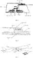
- a first compression-ring-type metal filler cap is mainly composed of an inner filler cap and a compression ring, as shown in Fig. 1 , the filler cap and the compression ring are made of aluminum alloy, the filler cap is formed by combining two parts between which a cavity is formed, a nut is fixedly disposed in the cavity and cooperates with a screw for connecting the compression ring to the filler cap to form a certain clamping force with a lower panel, and a sealing ring is disposed at a side where the outside of the filler cap is connected with the inside of the lower panel so that a sealing demand of the filler cap is met.
- a second compression-ring-type metal filler cap is mainly composed of an inner filler cap and a compression ring, as shown in Fig. 2 , the filler cap and the compression ring are made of aluminum alloy, the filler cap is machined, the middle of the filler cap is provided with a reinforcing rib, an anchor nut is fixedly disposed at the upper side of the filler cap and cooperates with a screw for connecting the compression ring to the filler cap to form a certain clamping force with the lower panel, and a sealing ring is disposed at a side where the outside of the filler cap is connected with the inside of the lower panel so that a sealing demand of the filler cap is met.
- the present invention provides an aircraft wing fuel tank filler cap and a structure in a circumferential region of the filler cap so as to realize the design and manufacture of a composite filler cap, avoid galvanic corrosion brought by single aluminum alloy filler cap, improve the rigidity of the inner filler cap and also reduce the weight of the wing filler cap.
- the present invention provides an aircraft wing fuel tank filler cap, comprising an inner filler cap, an outer filler cap, a sandwich layer, a fixing piece and a fastener;
- the aircraft wing fuel tank filler cap further comprises a sealing strip as well as an inner filler cap interior skin and a sunken inner filler cap skin on the inner filler cap;
- the sandwich layer is of a composite honeycomb sandwich structure or a foam sandwich structure.
- the outer filler cap is of a titanium alloy structure or an aluminum alloy structure.
- the fastener is an adhesive rivetless floating anchor self-locking nut; and the fixing piece is a bolt.
- the sealing strip is a silicon rubber sealing strip
- the silicon rubber sealing strip is embedded between the wing lower panel and the inner filler cap interior skin; and the silicon rubber sealing strip is M-shaped or O-shaped.
- the sealing strip is a polytetrafluoroethylene sealing strip
- the polytetrafluoroethylene sealing strip is attached to a junction of the wing lower panel and the inner filler cap interior skin.
- the bolt passes through the fixing hole in the outer filler cap and the sunken inner filler cap skin and is connected with the adhesive rivetless floating anchor self-locking nut.
- the inner filler cap further comprises an L-shaped piece or a U-shaped piece, and the L-shaped piece or the U-shaped piece is connected with the inner filler cap through a hot melt adhesive film.
- a structure in a circumferential region of an aircraft wing fuel tank filler cap comprises the above-mentioned aircraft wing fuel tank filler cap, wherein the wing lower panel comprises an intercalation sunken region at filler cap of wing lower panel and a plurality of stringers;
- the present invention can achieve the following technical effects: the titanium alloy or aluminum alloy outer filler cap is disposed to guarantee the demands on the shock resistance and lightning protection of the fuel tank filler cap, play a role in protecting a composite inner filler cap and improve the rigidity of the fuel tank filler cap; the composite inner filler cap is capable of effectively reducing the weight of a fuel tank filler cap assembly and also reducing the weight of a wing, so that galvanic corrosion brought by a single aluminum alloy filler cap is avoided; the wing lower panel is provided with the intercalation sunken region at filler cap of wing lower panel, this region is designed to provide a flat mounting region for the composite inner filler cap, also guarantee fitting of the outer filler cap and the lower panel, avoid filler caps from protruding and effectively increase the aerodynamic efficiency of the wing; the composite inner filler cap is formed by co-cementing, the sandwich layer adopts a honeycomb structure or a foam structure, thereby providing a certain rigidity, guaranteeing the demand on oil pressure
- the present invention provides an aircraft wing fuel tank filler cap and a structure in a circumferential region of the filler cap, as shown in Fig. 3 to Fig. 4 , mainly comprising a wing lower panel 5, a first stringer 4, a second stringer 8, a composite inner filler cap 7, a metal outer filler cap 9, a sealing strip 72 and the like. As shown in Fig. 5 to Fig.
- the wing lower panel 5 is provided with an intercalation sunken region at filler cap of wing lower panel 6, this region provides a flat mounting region for the composite inner filler cap 7 and also guarantees fitting of the outer filler cap 9 and the wing lower panel 5 and avoids the phenomenon that the outer filler cap 9 protrudes to affect the aerodynamic efficiency of a wing; and when the wing lower panel 5 is manufactured, the wing lower panel 5 and the intercalation sunken region at filler cap of wing lower panel 6 are integrally formed.
- An inner filler cap 7 can also be referred to as the composite inner filler cap 7, and an outer filler cap 9 can also be referred to as the metal outer filler cap 9.
- wing lower panel 5 can be generally provided with a plurality of stringers, and two stringers described herein can be understood for the purpose of clearer illustration.
- the composite inner filler cap 7 is composed of an inner filler cap interior skin 71, a sunken inner filler cap skin 76, a sandwich layer 73 and an adhesive rivetless floating anchor self-locking nut 74 (fastener).
- the sandwich layer 73 can adopt a honeycomb sandwich structure or a foam sandwich structure, thereby providing a certain rigidity, guaranteeing the demand on oil pressure of a fuel tank, and also guaranteeing the manufacture feasibility and the service performance and meeting the sealing and detaching demands of the inner filler cap.
- the honeycomb interlayer structure or the honeycomb sandwich structure refers to a laminated composite sandwiched with a lightweight core material between two thin skins.
- the honeycomb interlayer structure or the honeycomb sandwich structure is similar to an I-section beam visible on a steel rail. That is, two flanges of an I-section material correspond to the skins to bear a bending stress, a web plate of the I-section material corresponds to a core material to specially bear lateral shear, and therefore, their functions are divided clearly.
- the foam sandwich structure is a composite structure composed of two rigid panels and a foam core sandwiched therebetween.
- the panels are lightweight high-strength aluminum alloy plates or carbon fiber, glass fiber and aramid composite laminates; and the foam core is made of foamed plastics such as thermosetting phenolic, epoxy and acrylic acid and foamed plastics such as thermoplastic polyurethane, polystyrene and polyvinyl chloride.
- the foamed interlayer structure has the characteristics of high flexural rigidity, light weight, sufficient utilization of material strength and good low temperature resistance, but has lower shearing strength than a Nomex honeycomb interlayer structure under the same density.
- one of the methods comprises that a foam core material is firstly manufactured by machining according to the shape of a part and is then bonded with a skin material, wherein the skin can be a rigid plate, or a fiber (fabric)-impregnated resin is prepared into a prepreg to be laid on the core material; and the other method comprises that panels are firstly manufactured to be fixed to surrounding bulkheads, a foam material is placed in a space defined by the panels and the bulkheads, and the foam material is capable of filling the space to manufacture the interlayer structure.
- the overall performance of the material depends on the materials of the panels and the core material, for example, the interlayer structure made of a rigid polyurethane or acrylic foam core can be used as a bearing structural member, but a flexible foam interlayer structure made of thermoplastic resin is great in deformation when bearing a force so as to be used as a damping and sound insulating part.
- the foam interlayer structure is most applied to aircrafts, ships, sports and medical instruments, for example, the foam interlayer structure is used for manufacturing cabin doors of aircrafts, rudders, helicopter rotors, panels of aircrafts and ships, snowboards and surfboards in sports goods, medical CT couches and the like.
- the metal outer filler cap 9 is made of a metal material and is provided with a bevel edge matched with the wing lower panel 5, so that an assembly demand is met; a certain bolt hole (fixing hole) is provided to guarantee the assembly of the inner filler cap 7 and the outer filler cap 9, so that a certain clamping force is formed; and a non-bearing filler cap solution is provided to meet the functional demand of the filler cap.
- a bolt 77 fixing piece passes through the bolt hole in the outer filler cap 9 and the sunken inner filler cap skin 76 at the lower part of the inner filler cap and is connected with the adhesive rivetless floating anchor self-locking nut 74.
- the self-locking nut generally works by virtue of a friction force according to a principle of pressing embossed teeth into a preset hole of a metal plate, and generally, the pore diameter of the preset hole is slightly smaller than that of a clinch nut.
- the nut is connected with a locking mechanism, when the nut is screwed, a ruler body is locked by the locking mechanism, and a ruler frame is incapable of freely moving, so that a locking purpose is achieved; and when the nut is unscrewed, the ruler body is unlocked by the locking mechanism, and the ruler frame moves along the ruler body.
- a high-strength self-locking nut which serves as a kind of self-locking nut and has high strength and high reliability
- a nylon self-locking nut which is a novel anti-loose fastening part with high vibration resistance and can be applied to various machines and electrical products with the temperatures of -50 to 100°C
- a floating self-locking nut which is a double-lug sealing and floating self-locking nut composed of four parts comprising a sealing cover, a self-locking nut, a pressing ring and a sealing ring
- a spring self-locking nut which is a spring clamp self-locking nut composed of an S-shaped spring clamp and a self-locking nut.
- the self-locking nut is applied to the fields of railway casting, rail traffic, driving systems, mining equipment, highways, military application, oil extraction machinery, automobile industry, communal facilities, subways, engines, building machinery, aerospace, drilling equipment, bridges, generators, agricultural machinery, ship industry, metallurgical equipment, trains, compressors, medical instruments, signal systems and wind power generation.
- the sealing strip 72 can adopt an O-shaped or M-shaped silicon rubber sealing strip and is embedded into the inner filler cap 7 to play a sealing role.
- the sealing strip can also adopt an in-line sealing strip which is made of a polytetrafluoroethylene material and is attached between the inner filler cap 7 and the skin of the wing lower panel 5 to play a sealing role.
- the wing lower panel 5 is provided with the intercalation sunken region at filler cap of wing lower panel 6, this region is designed to provide a flat mounting region for the composite inner filler cap, also guarantee fitting of the outer filler cap 9 and the wing lower panel 5, avoid the outer filler cap 9 from protruding and effectively increase the aerodynamic efficiency of the wing.
- the inner filler cap 7 is pressurized to 3-6 atmospheric pressures during curing, which can result in the situation that a composite foam sandwich or a honeycomb sandwich is incapable of tightly fitting to the fastener (such as the adhesive rivetless floating anchor self-locking nut 74), and furthermore, there is a risk of local collapse; if there is such a situation, an L-shaped piece 78 or a U-shaped piece can be additionally disposed on a fastener (such as the adhesive rivetless floating anchor self-locking nut 74), the L-shaped piece 78 or U-shaped piece can be a composite piece or a metal piece; if the L-shaped piece 78 or U-shaped piece is the metal piece, it is possible to generate the problem of galvanic corrosion, glass-fiber fabric has to be locally laid for preventing galvanic corrosion; and the
- a hot melt adhesive film is a film product with or without release paper and can be conveniently subjected to continuous or intermittent operation so as to be widely applied to adhesion of various fabrics, sheets of paper, polymer materials and metals.
- the present embodiment provides a new solution of an aircraft wing fuel tank filler cap and a structure in a circumferential region of the filler cap.
- the periphery of a filler cap opening in a wing lower panel 5 is reinforced by intercalation and is set to be sunken to a certain extent to form an intercalation sunken region at filler cap of wing lower panel 6, the filler cap is designed to be a double-layer filler cap.
- an inner filler cap 7 is of a composite honeycomb sandwich or foam sandwich structure
- an outer filler cap 9 adopts a titanium alloy or aluminum alloy structure
- the inner filler cap 7 is formed by co-cementing
- a sunken inner filler cap skin 76 is firstly formed
- an adhesive rivetless floating anchor self-locking nut 74 is adhered to an appropriate position by using an adhesive 75, after curing is completed, the adhesive rivetless floating anchor self-locking nut 74 is filled with a honeycomb sandwich or foam sandwich and is co-cemented with an inner filler cap interior skin 71
- the outer ring of the inner filler cap 7 is provided with a silicon rubber or polytetrafluoroethylene sealing ring rubber strip to guarantee a demand on the sealing between the filler cap and the wing lower panel 5.
- a silicon rubber sealing strip is embedded between the intercalation sunken region at filler cap of wing lower panel 6 and the inner filler cap interior skin 71; and a polytetrafluoroethylene sealing strip is attached to a junction of the intercalation sunken region at filler cap of wing lower panel 6 and the inner filler cap interior skin 71.
- the outer filler cap 9 is designed according to the shape of the intercalation sunken region at filler cap of wing lower panel 6 and the position of the adhesive rivetless floating anchor self-locking nut 74, so that the demands on the shock resistance and lightning protection of the filler cap are guaranteed. As shown in Fig.
- a bolt passes through a bolt hole in the outer filler cap 9 and the sunken inner filler cap skin 76 and is connected with the adhesive rivetless floating anchor self-locking nut 76.
- the wing lower panel 5 is provided with the intercalation sunken region at filler cap of wing lower panel 6, this region is designed to provide a flat mounting region for the composite inner filler cap, also guarantee fitting of the outer filler cap 9 and the wing lower panel 5, avoid the outer filler cap 9 from protruding and effectively increase the aerodynamic efficiency of the wing.
- the titanium alloy or aluminum alloy outer filler cap is disposed to guarantee the demands on the shock resistance and lightning protection of the fuel tank filler cap, play a role in protecting a composite inner filler cap and improve the rigidity of the fuel tank filler cap;
- the composite inner filler cap is capable of effectively reducing the weight of a fuel tank filler cap assembly and also reducing the weight of a wing, so that galvanic corrosion brought by a single aluminum alloy filler cap is avoided;
- the wing lower panel is provided with the intercalation sunken region at filler cap of wing lower panel, this region is designed to provide a flat mounting region for the composite inner filler cap, also guarantee fitting of the outer filler cap and the wing lower panel, avoid filler caps from protruding and effectively increase the aerodynamic efficiency of the wing;
- the composite inner filler cap is formed by co-cementing, the sandwich layer adopts a honeycomb structure or a foam structure, thereby providing a certain rigidity, guaranteeing the demand on oil pressure of a fuel tank, and also
Landscapes
- Engineering & Computer Science (AREA)
- Aviation & Aerospace Engineering (AREA)
- Mechanical Engineering (AREA)
- Laminated Bodies (AREA)
Applications Claiming Priority (2)
| Application Number | Priority Date | Filing Date | Title |
|---|---|---|---|
| CN202010969236.1A CN111924113A (zh) | 2020-09-15 | 2020-09-15 | 一种飞机机翼油箱口盖及口盖周侧区域的结构 |
| PCT/CN2020/135997 WO2022057115A1 (fr) | 2020-09-15 | 2020-12-14 | Couvercle d'accès de réservoir de carburant d'aile d'avion et structure de zone périphérique de couvercle d'accès |
Publications (3)
| Publication Number | Publication Date |
|---|---|
| EP3998193A1 true EP3998193A1 (fr) | 2022-05-18 |
| EP3998193A4 EP3998193A4 (fr) | 2022-10-26 |
| EP3998193B1 EP3998193B1 (fr) | 2024-11-06 |
Family
ID=73334865
Family Applications (1)
| Application Number | Title | Priority Date | Filing Date |
|---|---|---|---|
| EP20894945.3A Active EP3998193B1 (fr) | 2020-09-15 | 2020-12-14 | Couvercle d'accès de réservoir de carburant d'aile d'avion et structure de zone périphérique de couvercle d'accès |
Country Status (3)
| Country | Link |
|---|---|
| EP (1) | EP3998193B1 (fr) |
| CN (1) | CN111924113A (fr) |
| WO (1) | WO2022057115A1 (fr) |
Cited By (1)
| Publication number | Priority date | Publication date | Assignee | Title |
|---|---|---|---|---|
| US12325517B2 (en) | 2023-05-08 | 2025-06-10 | Embraer S.A. | Access cover panel assemblies especially useful to cover aircraft fuel tank access openings |
Families Citing this family (8)
| Publication number | Priority date | Publication date | Assignee | Title |
|---|---|---|---|---|
| CN111924113A (zh) * | 2020-09-15 | 2020-11-13 | 中国商用飞机有限责任公司北京民用飞机技术研究中心 | 一种飞机机翼油箱口盖及口盖周侧区域的结构 |
| CN112896532A (zh) * | 2021-01-13 | 2021-06-04 | 中国商用飞机有限责任公司 | 油箱口盖及其制造工艺 |
| CN112918687B (zh) * | 2021-01-29 | 2022-08-02 | 东华大学 | 一种整体密封舱及其制备方法 |
| CN116654239B (zh) * | 2023-04-21 | 2026-03-20 | 中国直升机设计研究所 | 一种适用于具有水上迫降功能机型的快卸密封口盖组件 |
| CN117283907B (zh) * | 2023-10-08 | 2026-04-03 | 国营芜湖机械厂 | 一种飞机座舱盖破孔损伤快速密封修理装置及使用方法 |
| CN117416500A (zh) * | 2023-10-18 | 2024-01-19 | 中国商用飞机有限责任公司 | 用于飞机机翼油箱的抗冲击口盖 |
| CN117508557A (zh) * | 2023-11-22 | 2024-02-06 | 中航通飞华南飞机工业有限公司 | 一种满足水密舱要求的地板快卸口盖 |
| CN118560734B (zh) * | 2024-08-05 | 2024-12-06 | 中航(成都)无人机系统股份有限公司 | 一种无人机机翼整体油箱结构及制造方法 |
Family Cites Families (17)
| Publication number | Priority date | Publication date | Assignee | Title |
|---|---|---|---|---|
| US4291816A (en) * | 1980-07-09 | 1981-09-29 | Canadair Limited | Fuel tank access door for aircraft |
| US4579248A (en) * | 1983-11-10 | 1986-04-01 | The Boeing Company | Access panel assembly for aircraft fuel tank |
| ES2335837B1 (es) * | 2007-06-29 | 2011-02-18 | Airbus España, Sl. | Cubierta para boca de acceso de aeronave. |
| GB0817921D0 (en) * | 2008-10-01 | 2008-11-05 | Airbus Uk Ltd | Aircraft skin panel with ultrasonic gauge |
| GB201103190D0 (fr) * | 2011-02-24 | 2011-04-13 | Airbus Operations Ltd | |
| EP2746150B1 (fr) * | 2012-12-21 | 2017-04-05 | Airbus Operations S.L. | Couvercle d'accès de réservoir de carburant externe, aile et avion comprenant un tel couvercle |
| CN103470592B (zh) * | 2013-09-18 | 2015-05-13 | 贵州航天精工制造有限公司 | 一种用镶嵌件在软基材料上的连接固定方法 |
| CN105173056B (zh) * | 2015-08-12 | 2018-06-29 | 中国商用飞机有限责任公司北京民用飞机技术研究中心 | 一种机翼油箱防护口盖及其成型工艺 |
| CN204937461U (zh) * | 2015-08-12 | 2016-01-06 | 中国商用飞机有限责任公司北京民用飞机技术研究中心 | 一种机翼油箱防护口盖 |
| CN205076027U (zh) * | 2015-08-13 | 2016-03-09 | 中国航空工业集团公司西安飞机设计研究所 | 一种长桁上带有串气孔的机翼整体结构油箱 |
| FR3043062B1 (fr) * | 2015-10-28 | 2017-11-24 | Aviacomp | Porte d'acces au reservoir de carburant ou a une zone seche d'un aeronef |
| CN105889273A (zh) * | 2016-05-18 | 2016-08-24 | 贵州精立航太科技有限公司 | 一种游动自锁螺母组件及其无铆粘接方法 |
| CN106585957B (zh) * | 2016-12-14 | 2023-03-31 | 中航通飞研究院有限公司 | 一种复合材料机翼整体油箱及其制造方法 |
| CN207191447U (zh) * | 2017-08-31 | 2018-04-06 | 中国航空工业集团公司沈阳飞机设计研究所 | 一种可拆卸的油箱区口盖密封结构 |
| CN108583842B (zh) * | 2018-03-09 | 2020-07-14 | 彩虹无人机科技有限公司 | 一种用于薄膜蒙皮的复合材料轻质口盖机构 |
| CN212313890U (zh) * | 2020-09-15 | 2021-01-08 | 中国商用飞机有限责任公司北京民用飞机技术研究中心 | 一种飞机机翼油箱口盖及口盖周侧区域的结构 |
| CN111924113A (zh) * | 2020-09-15 | 2020-11-13 | 中国商用飞机有限责任公司北京民用飞机技术研究中心 | 一种飞机机翼油箱口盖及口盖周侧区域的结构 |
-
2020
- 2020-09-15 CN CN202010969236.1A patent/CN111924113A/zh active Pending
- 2020-12-14 EP EP20894945.3A patent/EP3998193B1/fr active Active
- 2020-12-14 WO PCT/CN2020/135997 patent/WO2022057115A1/fr not_active Ceased
Cited By (1)
| Publication number | Priority date | Publication date | Assignee | Title |
|---|---|---|---|---|
| US12325517B2 (en) | 2023-05-08 | 2025-06-10 | Embraer S.A. | Access cover panel assemblies especially useful to cover aircraft fuel tank access openings |
Also Published As
| Publication number | Publication date |
|---|---|
| EP3998193A4 (fr) | 2022-10-26 |
| CN111924113A (zh) | 2020-11-13 |
| EP3998193B1 (fr) | 2024-11-06 |
| WO2022057115A1 (fr) | 2022-03-24 |
Similar Documents
| Publication | Publication Date | Title |
|---|---|---|
| EP3998193B1 (fr) | Couvercle d'accès de réservoir de carburant d'aile d'avion et structure de zone périphérique de couvercle d'accès | |
| CN212313890U (zh) | 一种飞机机翼油箱口盖及口盖周侧区域的结构 | |
| EP2703283B1 (fr) | Aile d'avion composite collée | |
| EP2117922B1 (fr) | Panneau élastique pour avion | |
| US8695923B2 (en) | Window replacement for filling a window frame | |
| US8434716B2 (en) | Compliant crown panel for an aircraft | |
| EP2813425B1 (fr) | Cloison de pressurisation à auto-équilibrage | |
| US20040055248A1 (en) | Internally stiffened composite panels and methods for their manufacture | |
| US9079674B1 (en) | Composite structures for aerospace vehicles, and associated systems and methods | |
| EP0814018A2 (fr) | Ame de longeron ondulée à amplitude réduite | |
| US9027881B2 (en) | Composite material structure and aircraft wing provided therewith | |
| CA2031928A1 (fr) | Revetement resistant pour aeronef | |
| US9731807B2 (en) | Joints in fibre metal laminates | |
| US6478254B2 (en) | Skin/bulkhead structure | |
| EP2415662A1 (fr) | Structure de fuselage en matériau composite | |
| EP3546207A1 (fr) | Panneaux composites à absorption d'énergie | |
| US20230109860A1 (en) | Access arrangement for a wind turbine blade | |
| US20070264472A1 (en) | Sandwich Panel and a Method of Producing a Sandwich Panel | |
| AU2011281322A1 (en) | Aircraft thermal insulation | |
| US20200023933A1 (en) | Pressure bulkhead and method of installation | |
| EP4286737B1 (fr) | Réservoir d'hydrogène composite pour un aéronef | |
| Dincă et al. | Aluminum/glass fibre and aluminum/carbon fibre hybrid laminates | |
| WO2014183612A1 (fr) | Structure de fixation d'element transparent de poste de pilotage d'avion de chasse et son procede de fixation | |
| WO2002028709A1 (fr) | Bord d'ouverture de panneau de revetement composite et son procede de fabrication | |
| Foreman | Design Concepts for Composite Fuselage Structure |
Legal Events
| Date | Code | Title | Description |
|---|---|---|---|
| STAA | Information on the status of an ep patent application or granted ep patent |
Free format text: STATUS: UNKNOWN |
|
| STAA | Information on the status of an ep patent application or granted ep patent |
Free format text: STATUS: THE INTERNATIONAL PUBLICATION HAS BEEN MADE |
|
| PUAI | Public reference made under article 153(3) epc to a published international application that has entered the european phase |
Free format text: ORIGINAL CODE: 0009012 |
|
| STAA | Information on the status of an ep patent application or granted ep patent |
Free format text: STATUS: REQUEST FOR EXAMINATION WAS MADE |
|
| 17P | Request for examination filed |
Effective date: 20210611 |
|
| AK | Designated contracting states |
Kind code of ref document: A1 Designated state(s): AL AT BE BG CH CY CZ DE DK EE ES FI FR GB GR HR HU IE IS IT LI LT LU LV MC MK MT NL NO PL PT RO RS SE SI SK SM TR |
|
| RIN1 | Information on inventor provided before grant (corrected) |
Inventor name: XU, JIFENG Inventor name: WANG, JIANLI Inventor name: LUO, DAN Inventor name: MA, BO |
|
| A4 | Supplementary search report drawn up and despatched |
Effective date: 20220922 |
|
| RIC1 | Information provided on ipc code assigned before grant |
Ipc: B64C 1/14 20060101ALI20220916BHEP Ipc: B64C 3/34 20060101AFI20220916BHEP |
|
| DAV | Request for validation of the european patent (deleted) | ||
| DAX | Request for extension of the european patent (deleted) | ||
| GRAP | Despatch of communication of intention to grant a patent |
Free format text: ORIGINAL CODE: EPIDOSNIGR1 |
|
| STAA | Information on the status of an ep patent application or granted ep patent |
Free format text: STATUS: GRANT OF PATENT IS INTENDED |
|
| INTG | Intention to grant announced |
Effective date: 20240702 |
|
| RAP3 | Party data changed (applicant data changed or rights of an application transferred) |
Owner name: COMMERCIAL AIRCRAFT CORPORATION OF CHINA, LTD. Owner name: BEIJING AERONAUTICAL SCIENCE & TECHNOLOGY RESEARCHINSTITUTE,COMMERCIAL AIRCRAFT CORPORATION OF CHINA |
|
| GRAS | Grant fee paid |
Free format text: ORIGINAL CODE: EPIDOSNIGR3 |
|
| GRAA | (expected) grant |
Free format text: ORIGINAL CODE: 0009210 |
|
| STAA | Information on the status of an ep patent application or granted ep patent |
Free format text: STATUS: THE PATENT HAS BEEN GRANTED |
|
| AK | Designated contracting states |
Kind code of ref document: B1 Designated state(s): AL AT BE BG CH CY CZ DE DK EE ES FI FR GB GR HR HU IE IS IT LI LT LU LV MC MK MT NL NO PL PT RO RS SE SI SK SM TR |
|
| REG | Reference to a national code |
Ref country code: GB Ref legal event code: FG4D |
|
| REG | Reference to a national code |
Ref country code: CH Ref legal event code: EP |
|
| REG | Reference to a national code |
Ref country code: DE Ref legal event code: R096 Ref document number: 602020041075 Country of ref document: DE |
|
| REG | Reference to a national code |
Ref country code: IE Ref legal event code: FG4D |
|
| REG | Reference to a national code |
Ref country code: LT Ref legal event code: MG9D |
|
| REG | Reference to a national code |
Ref country code: NL Ref legal event code: MP Effective date: 20241106 |
|
| PG25 | Lapsed in a contracting state [announced via postgrant information from national office to epo] |
Ref country code: IS Free format text: LAPSE BECAUSE OF FAILURE TO SUBMIT A TRANSLATION OF THE DESCRIPTION OR TO PAY THE FEE WITHIN THE PRESCRIBED TIME-LIMIT Effective date: 20250306 Ref country code: PT Free format text: LAPSE BECAUSE OF FAILURE TO SUBMIT A TRANSLATION OF THE DESCRIPTION OR TO PAY THE FEE WITHIN THE PRESCRIBED TIME-LIMIT Effective date: 20250306 Ref country code: HR Free format text: LAPSE BECAUSE OF FAILURE TO SUBMIT A TRANSLATION OF THE DESCRIPTION OR TO PAY THE FEE WITHIN THE PRESCRIBED TIME-LIMIT Effective date: 20241106 |
|
| PG25 | Lapsed in a contracting state [announced via postgrant information from national office to epo] |
Ref country code: FI Free format text: LAPSE BECAUSE OF FAILURE TO SUBMIT A TRANSLATION OF THE DESCRIPTION OR TO PAY THE FEE WITHIN THE PRESCRIBED TIME-LIMIT Effective date: 20241106 Ref country code: NL Free format text: LAPSE BECAUSE OF FAILURE TO SUBMIT A TRANSLATION OF THE DESCRIPTION OR TO PAY THE FEE WITHIN THE PRESCRIBED TIME-LIMIT Effective date: 20241106 |
|
| REG | Reference to a national code |
Ref country code: AT Ref legal event code: MK05 Ref document number: 1739123 Country of ref document: AT Kind code of ref document: T Effective date: 20241106 |
|
| PG25 | Lapsed in a contracting state [announced via postgrant information from national office to epo] |
Ref country code: BG Free format text: LAPSE BECAUSE OF FAILURE TO SUBMIT A TRANSLATION OF THE DESCRIPTION OR TO PAY THE FEE WITHIN THE PRESCRIBED TIME-LIMIT Effective date: 20241106 |
|
| PG25 | Lapsed in a contracting state [announced via postgrant information from national office to epo] |
Ref country code: ES Free format text: LAPSE BECAUSE OF FAILURE TO SUBMIT A TRANSLATION OF THE DESCRIPTION OR TO PAY THE FEE WITHIN THE PRESCRIBED TIME-LIMIT Effective date: 20241106 |
|
| PG25 | Lapsed in a contracting state [announced via postgrant information from national office to epo] |
Ref country code: NO Free format text: LAPSE BECAUSE OF FAILURE TO SUBMIT A TRANSLATION OF THE DESCRIPTION OR TO PAY THE FEE WITHIN THE PRESCRIBED TIME-LIMIT Effective date: 20250206 |
|
| PG25 | Lapsed in a contracting state [announced via postgrant information from national office to epo] |
Ref country code: GR Free format text: LAPSE BECAUSE OF FAILURE TO SUBMIT A TRANSLATION OF THE DESCRIPTION OR TO PAY THE FEE WITHIN THE PRESCRIBED TIME-LIMIT Effective date: 20250207 Ref country code: LV Free format text: LAPSE BECAUSE OF FAILURE TO SUBMIT A TRANSLATION OF THE DESCRIPTION OR TO PAY THE FEE WITHIN THE PRESCRIBED TIME-LIMIT Effective date: 20241106 Ref country code: AT Free format text: LAPSE BECAUSE OF FAILURE TO SUBMIT A TRANSLATION OF THE DESCRIPTION OR TO PAY THE FEE WITHIN THE PRESCRIBED TIME-LIMIT Effective date: 20241106 |
|
| PG25 | Lapsed in a contracting state [announced via postgrant information from national office to epo] |
Ref country code: PL Free format text: LAPSE BECAUSE OF FAILURE TO SUBMIT A TRANSLATION OF THE DESCRIPTION OR TO PAY THE FEE WITHIN THE PRESCRIBED TIME-LIMIT Effective date: 20241106 |
|
| PG25 | Lapsed in a contracting state [announced via postgrant information from national office to epo] |
Ref country code: RS Free format text: LAPSE BECAUSE OF FAILURE TO SUBMIT A TRANSLATION OF THE DESCRIPTION OR TO PAY THE FEE WITHIN THE PRESCRIBED TIME-LIMIT Effective date: 20250206 |
|
| PG25 | Lapsed in a contracting state [announced via postgrant information from national office to epo] |
Ref country code: SM Free format text: LAPSE BECAUSE OF FAILURE TO SUBMIT A TRANSLATION OF THE DESCRIPTION OR TO PAY THE FEE WITHIN THE PRESCRIBED TIME-LIMIT Effective date: 20241106 |
|
| PG25 | Lapsed in a contracting state [announced via postgrant information from national office to epo] |
Ref country code: DK Free format text: LAPSE BECAUSE OF FAILURE TO SUBMIT A TRANSLATION OF THE DESCRIPTION OR TO PAY THE FEE WITHIN THE PRESCRIBED TIME-LIMIT Effective date: 20241106 |
|
| PG25 | Lapsed in a contracting state [announced via postgrant information from national office to epo] |
Ref country code: EE Free format text: LAPSE BECAUSE OF FAILURE TO SUBMIT A TRANSLATION OF THE DESCRIPTION OR TO PAY THE FEE WITHIN THE PRESCRIBED TIME-LIMIT Effective date: 20241106 |
|
| PG25 | Lapsed in a contracting state [announced via postgrant information from national office to epo] |
Ref country code: RO Free format text: LAPSE BECAUSE OF FAILURE TO SUBMIT A TRANSLATION OF THE DESCRIPTION OR TO PAY THE FEE WITHIN THE PRESCRIBED TIME-LIMIT Effective date: 20241106 |
|
| PG25 | Lapsed in a contracting state [announced via postgrant information from national office to epo] |
Ref country code: SK Free format text: LAPSE BECAUSE OF FAILURE TO SUBMIT A TRANSLATION OF THE DESCRIPTION OR TO PAY THE FEE WITHIN THE PRESCRIBED TIME-LIMIT Effective date: 20241106 |
|
| PG25 | Lapsed in a contracting state [announced via postgrant information from national office to epo] |
Ref country code: CZ Free format text: LAPSE BECAUSE OF FAILURE TO SUBMIT A TRANSLATION OF THE DESCRIPTION OR TO PAY THE FEE WITHIN THE PRESCRIBED TIME-LIMIT Effective date: 20241106 |
|
| PG25 | Lapsed in a contracting state [announced via postgrant information from national office to epo] |
Ref country code: IT Free format text: LAPSE BECAUSE OF FAILURE TO SUBMIT A TRANSLATION OF THE DESCRIPTION OR TO PAY THE FEE WITHIN THE PRESCRIBED TIME-LIMIT Effective date: 20241106 |
|
| REG | Reference to a national code |
Ref country code: CH Ref legal event code: PL |
|
| REG | Reference to a national code |
Ref country code: DE Ref legal event code: R097 Ref document number: 602020041075 Country of ref document: DE |
|
| PG25 | Lapsed in a contracting state [announced via postgrant information from national office to epo] |
Ref country code: LU Free format text: LAPSE BECAUSE OF NON-PAYMENT OF DUE FEES Effective date: 20241214 |
|
| PG25 | Lapsed in a contracting state [announced via postgrant information from national office to epo] |
Ref country code: SE Free format text: LAPSE BECAUSE OF FAILURE TO SUBMIT A TRANSLATION OF THE DESCRIPTION OR TO PAY THE FEE WITHIN THE PRESCRIBED TIME-LIMIT Effective date: 20241106 |
|
| PLBE | No opposition filed within time limit |
Free format text: ORIGINAL CODE: 0009261 |
|
| STAA | Information on the status of an ep patent application or granted ep patent |
Free format text: STATUS: NO OPPOSITION FILED WITHIN TIME LIMIT |
|
| PG25 | Lapsed in a contracting state [announced via postgrant information from national office to epo] |
Ref country code: MC Free format text: LAPSE BECAUSE OF FAILURE TO SUBMIT A TRANSLATION OF THE DESCRIPTION OR TO PAY THE FEE WITHIN THE PRESCRIBED TIME-LIMIT Effective date: 20241106 |
|
| REG | Reference to a national code |
Ref country code: BE Ref legal event code: MM Effective date: 20241231 |
|
| 26N | No opposition filed |
Effective date: 20250807 |
|
| PG25 | Lapsed in a contracting state [announced via postgrant information from national office to epo] |
Ref country code: BE Free format text: LAPSE BECAUSE OF NON-PAYMENT OF DUE FEES Effective date: 20241231 |
|
| PG25 | Lapsed in a contracting state [announced via postgrant information from national office to epo] |
Ref country code: CH Free format text: LAPSE BECAUSE OF NON-PAYMENT OF DUE FEES Effective date: 20241231 |
|
| PG25 | Lapsed in a contracting state [announced via postgrant information from national office to epo] |
Ref country code: IE Free format text: LAPSE BECAUSE OF NON-PAYMENT OF DUE FEES Effective date: 20241214 |
|
| GBPC | Gb: european patent ceased through non-payment of renewal fee |
Effective date: 20250206 |
|
| PG25 | Lapsed in a contracting state [announced via postgrant information from national office to epo] |
Ref country code: GB Free format text: LAPSE BECAUSE OF NON-PAYMENT OF DUE FEES Effective date: 20250206 |
|
| PGFP | Annual fee paid to national office [announced via postgrant information from national office to epo] |
Ref country code: FR Payment date: 20251222 Year of fee payment: 6 |
|
| PGFP | Annual fee paid to national office [announced via postgrant information from national office to epo] |
Ref country code: DE Payment date: 20251229 Year of fee payment: 6 |