EP3998210A1 - Ventilvorrichtung zur steuerung eines fluidstroms durch einen kanal oder eine öffnung einer klimaanlage eines flugzeuges - Google Patents
Ventilvorrichtung zur steuerung eines fluidstroms durch einen kanal oder eine öffnung einer klimaanlage eines flugzeuges Download PDFInfo
- Publication number
- EP3998210A1 EP3998210A1 EP21158207.7A EP21158207A EP3998210A1 EP 3998210 A1 EP3998210 A1 EP 3998210A1 EP 21158207 A EP21158207 A EP 21158207A EP 3998210 A1 EP3998210 A1 EP 3998210A1
- Authority
- EP
- European Patent Office
- Prior art keywords
- damper
- hole
- valve seat
- valve apparatus
- valve
- Prior art date
- Legal status (The legal status is an assumption and is not a legal conclusion. Google has not performed a legal analysis and makes no representation as to the accuracy of the status listed.)
- Granted
Links
Images


Classifications
-
- B—PERFORMING OPERATIONS; TRANSPORTING
- B64—AIRCRAFT; AVIATION; COSMONAUTICS
- B64D—EQUIPMENT FOR FITTING IN OR TO AIRCRAFT; FLIGHT SUITS; PARACHUTES; ARRANGEMENT OR MOUNTING OF POWER PLANTS OR PROPULSION TRANSMISSIONS IN AIRCRAFT
- B64D13/00—Arrangements or adaptations of air-treatment apparatus for aircraft crew or passengers, or freight space
-
- Y—GENERAL TAGGING OF NEW TECHNOLOGICAL DEVELOPMENTS; GENERAL TAGGING OF CROSS-SECTIONAL TECHNOLOGIES SPANNING OVER SEVERAL SECTIONS OF THE IPC; TECHNICAL SUBJECTS COVERED BY FORMER USPC CROSS-REFERENCE ART COLLECTIONS [XRACs] AND DIGESTS
- Y02—TECHNOLOGIES OR APPLICATIONS FOR MITIGATION OR ADAPTATION AGAINST CLIMATE CHANGE
- Y02T—CLIMATE CHANGE MITIGATION TECHNOLOGIES RELATED TO TRANSPORTATION
- Y02T50/00—Aeronautics or air transport
- Y02T50/40—Weight reduction
Definitions
- the present invention refers to a valve apparatus for controlling fluid flow through a duct or opening of an air conditioning system of an aircraft.
- the aircraft may be an aircraft having vertical take-off and landing (VTOL) capabilities.
- the VTOL aircraft may have an electrically driven propulsion system (eVTOL).
- weight reduction is crucial when working out the vehicle design.
- the weight reduction requirement is in particular known in the field of aircraft.
- a solenoid actuator which is well known as such, for actuating a valve apparatus according to the present invention provides at the same time both a lightweight and simple design.
- a solenoid actuator has an electromagnet and an actuator rod that is driven by the electromagnet in known manner.
- the lift of the actuator rod that may be obtained from a solenoid actuator is limited.
- the actuator force of a solenoid actuator significantly depends on the actual lift of the actuator rod.
- the present invention provides a solution for using a solenoid actuator in a valve apparatus even in view of the aforementioned properties of a solenoid actuator with regard to the available extent of lift and the available actuator force.
- the present invention proposes a valve apparatus for controlling fluid flow especially through a duct or opening of an air conditioning system of an aircraft.
- the valve apparatus comprises a valve seat body having a valve seat hole being configured to allow the fluid, especially air, to flow through it and a damper body for closing the valve seat hole thereby stopping the fluid from flowing through it.
- the valve seat body and the damper body are movable relative to each other between an open configuration and a closed configuration. In the open configuration, the fluid may flow through the valve seat hole, and in the closed configuration, the damper body interacts with the valve seat body in a sealing manner such that the fluid may not flow through the valve seat hole.
- the valve seat hole has a hole contour formed by a hole edge
- the damper body has a damper contour formed by a damper edge.
- the hole edge and the damper edge are configured to interact with each other in the sealing manner, thereby forming a circumferential sealing line having a circumferential sealing length.
- the hole contour has a plurality of hole protuberances and the damper contour has a plurality of damper protrusions.
- the hole protuberances and the damper protrusions correspond to each other in order to ensure effective sealing along the circumferential sealing line in the closed configuration.
- the hole protuberances and the damper protrusions have the effect that the circumferential sealing length is larger than a reference length being defined by a length of a circumference of an equal area circle having a circle area that equals to the area of the valve seat hole.
- the aerodynamic gap i.e. the flow cross-section, between the hole edge and the damper edge in the open configuration is approximately the length of the circumferential sealing line, i.e. the circumferential sealing length, times the lift of the actuator rod of the solenoid actuator.
- the circumferential sealing length in the sense of the present invention in comparison to the length of the circumference of the equal area circle, the size of the aerodynamic gap is significantly enlarged while the lift of the actuator rod remains the same.
- the solenoid actuator provides limited lift as such, the present invention ensures that, when using the same size of cross-sectional area of the duct for piping the fluid, a size of the aerodynamic gap may be reached that is comparable to the sizes of aerodynamic gaps that can be achieved in the prior art by torque motors or geared drives allowing non-limited lift in combination with commonly shaped valve seat holes and damper bodies.
- the disadvantageous property of a limited lift of a solenoid actuator is thus overcome by the enlarged circumferential sealing length according to the present invention.
- the equal area circle is an imaginary circle. Its circle area has the same size as the area of the valve seat hole having the hole protuberances. Accordingly, based on the same sizes but different shapes of area, the circumferential sealing length is put into relation to the circular circumference of the imaginary equal area circle.
- the damper body may be biased relative to the valve seat body towards the open configuration or towards the closed configuration.
- the damper body may urge the damper body towards the open configuration by the bias and let the actuator force of the solenoid actuator act against the bias when moving the damper body towards the closed configuration.
- the bias may urge the damper body to its closed configuration and the actuator force of the solenoid actuator may act against the bias when moving the damper body towards the open configuration.
- the actuator force of the solenoid actuator is transmitted through the actuator rod.
- the solenoid actuator is mounted for moving the damper body relative to the valve seat body towards the closed or open configuration.
- the solenoid actuator may apply actuator force in bidirectional manner without necessity of any bias towards one of the open and closed configurations. However, if for some reason bias towards one of the open and closed configurations is preferred the actuator force always acts against the bias.
- Force transmission means are arranged between the actuator rod and the damper body for acting there between.
- the force transmission means are configured to apply a closing force to the damper body that is larger than the actuator force.
- the ratio between the closing force and the actuator force is preferably at least 5, more preferably at least 20 and most preferably at least 50.
- the force transmission means have the advantageous effect that a closing force considerably larger than the lift-depending actuator force may be applied to the damper body in its closed position.
- the solenoid actuator may advantageously be operated in a hold mode with relatively small electric load thereby preventing the solenoid actuator from damage.
- the present invention alternatively proposes a valve apparatus having the features of claim 2.
- the damper body in the valve apparatus according to claim 2 may be driven by any kind of driving unit that has the drawback of providing a limited lift only.
- the damper body may in particular be driven by a solenoid actuator as long as a lift-depending and rather small actuator force is acceptable and the focus is on overcoming the drawback of limited lift.
- the ratio of the circumferential sealing length to the reference length is preferably at least 1,5, more preferably at least 2,0 and most preferably at least 2,5.
- a plurality of different shapes may be envisaged.
- a hole or damper contour would be a star-shaped hole or damper contour having a number of star fingers radially extending from a center region of the star shape.
- Another example of a possible hole or damper contour would be a star-shaped hole contour having one group of star fingers with a larger radial length and another group of star fingers with a smaller radial length.
- all of the hole protuberances and all of the damper protrusions may have the same shape and size.
- the hole protuberances and the damper protrusions preferably have a finger-like shape.
- Finger-like shape in the sense of the present invention means that the respective hole protuberance or damper protrusion is longer than wide.
- the valve seat hole may have a central region, and the hole protuberances may extend from opposite sides of the central region.
- the damper body may have a central portion, and the damper protrusions may extend from opposite sides of the central portions.
- the hole protuberances on each of the opposite sides of the central region may extend with their geometrical axes directed away from the central region parallel to each other.
- the damper protrusions on each of the opposite sides of the central portion may extend with their geometrical axes directed away from the central portion parallel to each other.
- Each hole protuberance on one of the opposite sides of the central region may be aligned with one hole protuberance on the other of the opposite sides of the central region.
- each damper protrusion on one of the opposite sides of the central portion may be aligned with one damper protrusion on the other of the opposite sides of the central portion.
- the present invention alternatively further proposes a valve apparatus having the features of claim 11.
- a valve apparatus having the features of claim 11.
- all explanations made herein also apply to the valve apparatus according to claim 11 in a corresponding manner.
- This valve apparatus may be used when the limited lift of known solenoid actuators is acceptable and only an increased closing force acting on the damper body is important. Then, the valve apparatus may for example have a circular damper body that forms a circular sealing line when interacting with a circular valve seat hole.
- the force transmission means in the sense of the present invention may be any kind of means that applies a closing force to the damper body that is larger than the actuator force.
- gear transmission means including oval gears may be used as the force transmission means.
- the force transmission means are formed by a knee-lever mechanism comprising at least first and second levers being rotatably connected with each other by a knee joint.
- the actuator rod of the solenoid actuator may be rotatably connected with the first lever by a rod joint.
- the first and second levers may be moved to a flexed relative position corresponding to the open configuration.
- the first and second levers may be further moved to a stretched relative position corresponding to the closed configuration of the valve apparatus.
- At least one of the first and second levers may have stop means at least for stopping further rotational movement beyond the stretched relative position of the first and second levers.
- movement of the first and second levers are stopped at least slightly before they reach a fully stretched relative position in which they are exactly aligned.
- suitable initiating means for initiating controlled flexing movement out of the fully stretched relative position towards the flexed relative position are provided.
- suitable initiating means may for example be springs that need to develop just a small force for initiating the flexing movement.
- the solenoid actuator may be pivotably mounted on a fixed supporting beam.
- the supporting beam itself may be fixed to the valve seat body by mounting bars.
- the damper body may be fixed to a movably guided traverse.
- the traverse may be movably guided by the mounting bars for mounting the supporting beam.
- the mounting bars serve a double function, namely fixing the supporting beam to the valve seat body on the one hand and movably guiding the traverse carrying the damper body on the other hand. Weight reduction is thereby achieved because no separate guiding means for guiding the traverse are necessary beyond the mounting bars.
- Springs may be fitted to the mounting bars for urging the traverse towards the supporting beam or for urging the traverse towards the valve seat body, thereby effecting bias towards the open or the closed configuration.
- the springs may be pressure springs acting between the valve seat body and the traverse or tension springs acting between the supporting beam and the traverse when bias towards the open configuration is intended.
- the first lever may be rotatably connected with the supporting beam by a beam joint.
- the second lever may be rotatably connected with the traverse by a traverse joint.
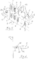
- Figs. 1 through 15 show the same embodiment of a valve apparatus 1 according to the present invention.
- Figs. 1 through 6 show the open configuration of valve apparatus 1 while Figs. 7 through 14 show the closed configuration of valve apparatus 1.
- the bottom plan view according to Fig. 15 is identical for both the open configuration and the closed configuration.
- Like reference numerals in different drawings refer to like elements of valve apparatus 1.
- Fig. 1 shows valve apparatus 1 in a perspective view from the top. It has a rectangular valve seat body 2 suitable to be mounted in a corresponding cross-section of a duct (not shown) or opening (not shown) for piping a fluid.
- the fluid is air.
- a fluid other than air may flow through valve apparatus 1.
- valve seat body 2 is shown with a rectangular outer shape, it is noted that the outer shape of valve seat body 2 may deviate from a rectangular or square shape and may for example take a circular shape for ducts or openings having a circular cross section or shape.
- valve seat body 2 is adapted to be mounted in the cross section of a duct in a manner that seals between the outer edge of valve seat body 2 and the inner wall of the duct. Fluid is not allowed to flow between the outer edge of valve seat body 2 and the inner wall of the duct that surrounds the outer edge of valve seat body 2.
- Valve seat body 2 has a valve seat hole 3 as marked in Fig. 4 . Fluid may flow through valve seat hole 3 when valve apparatus 1 is in its open configuration as in Figs. 1 through 6 .
- a damper body 4 may be moved from the open configuration shown in Fig. 4 to the closed configuration shown in Fig. 10 . In the open configuration, fluid may flow through valve seat hole 3 as marked by arrows F in Fig. 4 .
- Valve seat body 2 and damper body 4 are manufactured by deep or punch-drawing methods. Then, they have non-flat surfaces and sufficient structural stiffness. Alternatively, valve seat body 2 and damper body 4 may be obtained from other manufacturing methods resulting in flat surfaces. Structural stiffness may then be ensured by a honeycomb structure or the like.
- valve seat hole 3 and the damper body 4 have a double-comb like shape.
- Valve seat hole 3 is composed of an elongated central region 12 from which a total number of twelve hole protuberances extend away (see Figs. 5 and 11 ). On each of the two opposite sides of central region 12 there are six hole protuberances 7. As shown all of the hole protuberances 7 have the same finger-like shape and size. Further, in the present embodiment, the six hole protuberances 7 extending on one side of central region 12 are aligned with the six hole protuberances 7 extending on the other side of central region 12. All hole protuberances 7 have rounded tips as shown in the drawings.
- damper body 4 has an elongate central portion 13 from which twelve damper protrusions 8 extend away. As shown, six damper protrusions 8 extend on one side of central portion 13 and six damper protrusions 8 extend on the opposite side of central portion 13. As the hole protuberances 7 in valve seat hole 3, in the present embodiment, damper protrusions 8 have a corresponding finger-like shape and size with rounded tips. As in case of the hole protuberances 7, each of the six damper protrusions 8 extending on one side of central region 13 is aligned with a respective one of the six damper protrusions 8 extending on the other side of central region 13.
- hole protuberances 7 and damper protrusions 8 have exemplary character only. It is noted that other numbers, shapes and sizes of hole protuberances 7 and damper protrusions 8 may be applied in the sense of the present invention.
- Valve seat hole 3 is surrounded by its hole contour having a surrounding hole edge 5 as shown in Figs. 1 and 5 .
- Damper body 4 has its damper contour formed by a surrounding damper edge 6 as shown in Figs. 1 and 5 .
- surrounding damper edge 6 is spaced apart from surrounding hole edge 5 so that fluid may flow through a surrounding aerodynamic gap formed between damper edge 6 and hole edge 5.
- surrounding damper edge 6 abuts against surrounding hole edge 5 thereby forming a circumferential sealing line that has a circumferential sealing length.
- This circumferential sealing length corresponds to the length of the circumference of the double-comb shaped valve seat hole 3 or damper body 4.
- the sealing between hole edge 5 and damper edge 6 may be improved by sealing material applied to one ot both of them (coating or other application).
- the mass flow that may flow through a given aerodynamic gap depends on its size, i.e. the size of the cross-sectional area of the aerodynamic gap.
- the size of the aerodynamic gap may approximately be calculated as the product of the circumferential sealing length times the lift of damper body 4.
- the lift of damper body 4 is the distance by which damper body 4 has been moved in Fig. 10 upwards in vertical direction in order to arrive at its position corresponding to the open configuration shown in Fig. 4 .
- the size of the aerodynamic gap is significantly enlarged because the circumferential sealing length, i.e. the length of hole edge 5 or damper edge 6, is significantly enlarged. This is explained in the following more closely with reference to Fig. 15 .
- Fig. 15 depicts a bottom plan view of valve apparatus 1 with two additional circles that are no structural features of valve apparatus 1 but serve explanatory and comparative purposes. Damper body 4 with its central portion 13 and damper protrusions 8 may be seen through valve seat hole 3 in valve seat body 2.
- a smaller circle is marked as equal area circle EAC in Fig. 15 .
- the circle area of equal area circle EAC has the same size as the hole area enclosed by double-comb shaped hole contour of valve seat hole 3. Assuming that equal area circle EAC would form a damper contour of a damper body, the size of the area of the aerodynamic gap would be calculated as the circumferential length of equal area circle EAC times the lift of the damper body.
- the aerodynamic gap may be significantly larger than the one calculated on the basis of a circular damper contour according to equal area circle EAC.
- the circumferential sealing length of the double-comb like shaped hole or damper contour of the present embodiment is much longer than the circumferential length of equal area circle EAC.
- the circumferential sealing length of the double-comb like shape is as long as the circumference of comparative circle CC included in Fig. 15 for comparative purposes.
- the circumferential sealing length as with the double-comb shaped valve seat hole 3 and damper body 4 according to the present invention by means of a circular valve seat hole and damper body, it would be necessary to cover considerably more cross-sectional area and thus space because the duct or opening for piping the fluid would have to be enlarged in proportional manner.
- the increased cross-sectional area would require a higher closing force because the pressure difference acts on an increased area of the damper body.
- the present invention achieves much more circumferential sealing length while at the same time not covering more hole area than the one enclosed by equal area circle EAC.
- the circumferential sealing length of the double-comb shaped valve seat hole 3 and damper body 4, i.e. the circumference of comparative circle CC is approximately 3,5 times longer than the circumference of equal area circle EAC.
- the length of the circumference of equal area circle EAC serves as a reference parameter for the present invention. Number, shape and size of hole protuberances 7 and damper protrusions 8 may widely vary within the context of the present invention.
- the size of equal area circle EAC only varies in dependence of the hole size of valve seat hole 3 regardless of any specific shape of valve seat hole 3 under the present invention.
- valve seat hole 3 and damper body 4 may be formed like a star with star fingers radially extending outward and having the same radial length.
- not all twelve damper protrusions 8 in Fig. 15 may have the same length.
- every second damper protrusion may be only half as long as the respective neighbored damper protrusion 8.
- each of the six upper damper protrusions 8 in Fig. 15 could have different lengths in such a way that their rounded tip portions are located along an arc of a circle.
- damper body 4 is linearly movable between the open and the closed configurations.
- damper body 4 it would be alternatively feasible under the present invention to rotatably move damper body 4 between its open and closed configurations.
- the rotational lift (lift resulting from the angle of rotation) of damper body 4 would be rather small and the principle of calculating the size of the aerodynamic gap as discussed herein before could still be applied. It could be assumed that the lift of damper body 4 along the complete circumferential sealing line is constant for approximating the size of the aerodynamic gap.
- bias towards the open or closed configuration is preferred in this context for example a leaf or plate spring could be employed for effecting the bias.
- damper body 4 For linear movement of damper body 4 relative to valve seat body 2, damper body 4 is fixed to a traverse 21 that is movably guided along two mounting bars 20 as can be best seen in Figs. 1 , 3 , 7 , 9 and 13 .
- the two mounting bars 20 are fixed to valve seat body 2 by suitable means like screws or the like.
- Pressure springs 22 in the form of coil springs act between valve seat body 2 and traverse 21 in order to urge or bias traverse 21 together with damper body 4 away from the closed configuration according to Figs. 7 through 14 towards the open configuration according to Figs. 1 through 6 .
- Mounting bars 20 extend through opposite ends of traverse 21 and carry on their upper free ends a supporting beam 19.
- the supporting beam 19 is fixed at the upper ends of mounting bars 20 by suitable means like screws or the like. Accordingly, supporting beam 19 is not movable relative to valve seat body 2.
- Supporting beam 19 supports a solenoid actuator 9 having an actuator rod 10 best seen in Fig. 14 .
- Solenoid actuator 9 is mounted to support beam 19 by an actuator joint 25 as marked in Figs. 13 and 14 .
- Actuator joint 25 effects sufficient degree of rotational freedom for solenoid actuator 9 when traverse 21 and damper body 4 are moved between the open and closed configurations.
- force transmission means in the form of a knee-lever mechanism 11 are arranged between actuator rod 10 and traverse 21.
- Force transmission means at this place of valve apparatus 1 have the function to convert the relatively small actuator force delivered by actuator rod 10 into a relatively large closing force acting on traverse 21 and thus damper body 4 for reliably and safely pressing damper edge 6 against hole edge 5 in the closed configuration.
- solenoid actuator 9 is electrically activated actuator rod 10 extends and forces traverse 21 through knee-lever mechanism 11 against the bias of pressure springs 22 into the closed configuration. Switching solenoid actuator 9 currentless results in not applying a closing force to traverse 21 and the action of pressure springs 22 lifts traverse 21 together with damper body 4 thereby moving them to the open configuration.
- knee-lever mechanism 11 comprises a first lever 14 and a second lever 15.
- the first and second levers 14, 15 are rotatably connected with each other by knee joint 16.
- the lower free end of actuator rod 10 is rotatably connected with first lever 14 through rod joint 17.
- first lever 14 is rotatably mounted to support beam 19 through beam joint 23.
- Second lever 15 is rotatably mounted to traverse 21 by traverse joint 24.
- solenoid actuator 9 When solenoid actuator 9 is currentless, the action of pressure springs 22 urges first and second levers 14, 15 of knee-lever mechanism 11 to a flexed relative position as can be seen in Figs. 1 and 3 showing the situation of knee-lever mechanism 11 in the open configuration.
- Loading solenoid actuator 9 with current results in extending actuator rod 10 thereby pivoting first lever 14 clockwise around knee joint 23 and second lever 15 anticlockwise around traverse joint 24 to a stretched relative position in which first and second levers 14, 15 are not fully or exactly aligned as can be seen in Fig. 14 .
- second lever 15 transfers a closing force to traverse 21 and damper body 4 that sealingly presses damper edge 6 against hole edge 5 against the bias of pressure springs 22.
- first lever 14 has at its lower end in Fig. 14 a stop means 18 in the form of a bolt or the like.
- the bolt protrudes into the plane of projection of Fig. 14 so that it abuts against the right side edge of second lever 15 when knee-lever mechanism 11 reaches the stretched relative position according to Fig. 14 .
- Stop means 18 thereby provides for a collision between first and second levers 14, 15 and stops further rotational movement beyond the shown stretched relative position by positive locking.
Landscapes
- Health & Medical Sciences (AREA)
- General Health & Medical Sciences (AREA)
- Pulmonology (AREA)
- Engineering & Computer Science (AREA)
- Aviation & Aerospace Engineering (AREA)
- Lift Valve (AREA)
Priority Applications (1)
| Application Number | Priority Date | Filing Date | Title |
|---|---|---|---|
| EP21158207.7A EP3998210B1 (de) | 2021-02-19 | 2021-02-19 | Ventilvorrichtung zur steuerung eines fluidstroms durch einen kanal oder eine öffnung einer klimaanlage eines flugzeuges |
Applications Claiming Priority (1)
| Application Number | Priority Date | Filing Date | Title |
|---|---|---|---|
| EP21158207.7A EP3998210B1 (de) | 2021-02-19 | 2021-02-19 | Ventilvorrichtung zur steuerung eines fluidstroms durch einen kanal oder eine öffnung einer klimaanlage eines flugzeuges |
Publications (3)
| Publication Number | Publication Date |
|---|---|
| EP3998210A1 true EP3998210A1 (de) | 2022-05-18 |
| EP3998210B1 EP3998210B1 (de) | 2023-09-13 |
| EP3998210C0 EP3998210C0 (de) | 2023-09-13 |
Family
ID=74672212
Family Applications (1)
| Application Number | Title | Priority Date | Filing Date |
|---|---|---|---|
| EP21158207.7A Active EP3998210B1 (de) | 2021-02-19 | 2021-02-19 | Ventilvorrichtung zur steuerung eines fluidstroms durch einen kanal oder eine öffnung einer klimaanlage eines flugzeuges |
Country Status (1)
| Country | Link |
|---|---|
| EP (1) | EP3998210B1 (de) |
Cited By (1)
| Publication number | Priority date | Publication date | Assignee | Title |
|---|---|---|---|---|
| CN116123706A (zh) * | 2022-12-29 | 2023-05-16 | 珠海格力电器股份有限公司 | 风道结构及送风装置 |
Citations (7)
| Publication number | Priority date | Publication date | Assignee | Title |
|---|---|---|---|---|
| JPS4992048U (de) * | 1972-11-25 | 1974-08-09 | ||
| DE2315626A1 (de) * | 1973-03-29 | 1974-10-10 | Braukmann Armaturen | Armatur |
| US4557185A (en) * | 1984-07-26 | 1985-12-10 | Harriman Ronald M | Solenoid operated exhaust air damper |
| DE4438250A1 (de) * | 1994-10-26 | 1996-05-02 | Bosch Gmbh Robert | Abgasrückführventil |
| DE10162604B4 (de) * | 2001-12-20 | 2004-02-26 | Danfoss A/S | Heizkörperventil |
| DE102014204160A1 (de) * | 2014-03-06 | 2015-09-10 | Robert Bosch Gmbh | Ventil mit mindestens zwei Kniehebeln |
| CN108386585A (zh) * | 2018-03-13 | 2018-08-10 | 珠海励高精工制造有限公司 | 电子膨胀阀及空调器 |
-
2021
- 2021-02-19 EP EP21158207.7A patent/EP3998210B1/de active Active
Patent Citations (7)
| Publication number | Priority date | Publication date | Assignee | Title |
|---|---|---|---|---|
| JPS4992048U (de) * | 1972-11-25 | 1974-08-09 | ||
| DE2315626A1 (de) * | 1973-03-29 | 1974-10-10 | Braukmann Armaturen | Armatur |
| US4557185A (en) * | 1984-07-26 | 1985-12-10 | Harriman Ronald M | Solenoid operated exhaust air damper |
| DE4438250A1 (de) * | 1994-10-26 | 1996-05-02 | Bosch Gmbh Robert | Abgasrückführventil |
| DE10162604B4 (de) * | 2001-12-20 | 2004-02-26 | Danfoss A/S | Heizkörperventil |
| DE102014204160A1 (de) * | 2014-03-06 | 2015-09-10 | Robert Bosch Gmbh | Ventil mit mindestens zwei Kniehebeln |
| CN108386585A (zh) * | 2018-03-13 | 2018-08-10 | 珠海励高精工制造有限公司 | 电子膨胀阀及空调器 |
Cited By (1)
| Publication number | Priority date | Publication date | Assignee | Title |
|---|---|---|---|---|
| CN116123706A (zh) * | 2022-12-29 | 2023-05-16 | 珠海格力电器股份有限公司 | 风道结构及送风装置 |
Also Published As
| Publication number | Publication date |
|---|---|
| EP3998210B1 (de) | 2023-09-13 |
| EP3998210C0 (de) | 2023-09-13 |
Similar Documents
| Publication | Publication Date | Title |
|---|---|---|
| CN102686923B (zh) | 具有内载荷装置的电致动器 | |
| JP5716034B2 (ja) | 電動アクチュエータとともに使用するための結合装置 | |
| EP2812242B1 (de) | Aktuatorsystem und methode | |
| KR101697810B1 (ko) | 소형 액츄에이터 기어 세트 | |
| US10401051B2 (en) | Fail-safe actuating system | |
| EP3998210B1 (de) | Ventilvorrichtung zur steuerung eines fluidstroms durch einen kanal oder eine öffnung einer klimaanlage eines flugzeuges | |
| US9772029B2 (en) | Planetary carrier with spring clutch | |
| CN101617157A (zh) | 用在隔膜致动器中以改变有效弹簧刚度的装置 | |
| CN108700200B (zh) | 阀门系列 | |
| US20040076509A1 (en) | Electromagnetical clutch, electromechanical actuator and turbine | |
| EP3749884B1 (de) | Axial durchtrombares schnellschlussventil | |
| WO2015157157A1 (en) | Servo valve | |
| EP2107265A1 (de) | Drehmomentbegrenzer mit Bremse | |
| EP4047249B1 (de) | Ventilvorrichtung zur steuerung eines fluidstroms durch einen kanal oder eine öffnung | |
| EP3112771B1 (de) | Elektrischer stellantrieb für heizungs-, lüftungs- und klimaanlage | |
| US7185852B2 (en) | Actuator with helical cam guides | |
| US4055954A (en) | Damper actuator for a ventilation system | |
| CN113022841B (zh) | 致动器系统和用于控制飞行器的控制面的方法 | |
| WO2020041080A1 (en) | Air vent for a vehicle | |
| EP3997372B1 (de) | Ausfallsicherer aktuator und montageeinheit | |
| US20190346059A1 (en) | Actuator And Method For Setting An Actuator | |
| US20220154833A1 (en) | Multi-port rotary slide valve | |
| EP3387307B1 (de) | Ventil | |
| US20190366534A1 (en) | Robotic Arm Assembly | |
| HK1260873A1 (en) | Valve series |
Legal Events
| Date | Code | Title | Description |
|---|---|---|---|
| PUAI | Public reference made under article 153(3) epc to a published international application that has entered the european phase |
Free format text: ORIGINAL CODE: 0009012 |
|
| STAA | Information on the status of an ep patent application or granted ep patent |
Free format text: STATUS: THE APPLICATION HAS BEEN PUBLISHED |
|
| AK | Designated contracting states |
Kind code of ref document: A1 Designated state(s): AL AT BE BG CH CY CZ DE DK EE ES FI FR GB GR HR HU IE IS IT LI LT LU LV MC MK MT NL NO PL PT RO RS SE SI SK SM TR |
|
| STAA | Information on the status of an ep patent application or granted ep patent |
Free format text: STATUS: REQUEST FOR EXAMINATION WAS MADE |
|
| 17P | Request for examination filed |
Effective date: 20220812 |
|
| RBV | Designated contracting states (corrected) |
Designated state(s): AL AT BE BG CH CY CZ DE DK EE ES FI FR GB GR HR HU IE IS IT LI LT LU LV MC MK MT NL NO PL PT RO RS SE SI SK SM TR |
|
| GRAP | Despatch of communication of intention to grant a patent |
Free format text: ORIGINAL CODE: EPIDOSNIGR1 |
|
| STAA | Information on the status of an ep patent application or granted ep patent |
Free format text: STATUS: GRANT OF PATENT IS INTENDED |
|
| INTG | Intention to grant announced |
Effective date: 20230613 |
|
| GRAS | Grant fee paid |
Free format text: ORIGINAL CODE: EPIDOSNIGR3 |
|
| GRAA | (expected) grant |
Free format text: ORIGINAL CODE: 0009210 |
|
| STAA | Information on the status of an ep patent application or granted ep patent |
Free format text: STATUS: THE PATENT HAS BEEN GRANTED |
|
| AK | Designated contracting states |
Kind code of ref document: B1 Designated state(s): AL AT BE BG CH CY CZ DE DK EE ES FI FR GB GR HR HU IE IS IT LI LT LU LV MC MK MT NL NO PL PT RO RS SE SI SK SM TR |
|
| REG | Reference to a national code |
Ref country code: CH Ref legal event code: EP |
|
| REG | Reference to a national code |
Ref country code: DE Ref legal event code: R096 Ref document number: 602021005032 Country of ref document: DE |
|
| REG | Reference to a national code |
Ref country code: IE Ref legal event code: FG4D |
|
| U01 | Request for unitary effect filed |
Effective date: 20230913 |
|
| U07 | Unitary effect registered |
Designated state(s): AT BE BG DE DK EE FI FR IT LT LU LV MT NL PT SE SI Effective date: 20230920 |
|
| PG25 | Lapsed in a contracting state [announced via postgrant information from national office to epo] |
Ref country code: GR Free format text: LAPSE BECAUSE OF FAILURE TO SUBMIT A TRANSLATION OF THE DESCRIPTION OR TO PAY THE FEE WITHIN THE PRESCRIBED TIME-LIMIT Effective date: 20231214 |
|
| PG25 | Lapsed in a contracting state [announced via postgrant information from national office to epo] |
Ref country code: RS Free format text: LAPSE BECAUSE OF FAILURE TO SUBMIT A TRANSLATION OF THE DESCRIPTION OR TO PAY THE FEE WITHIN THE PRESCRIBED TIME-LIMIT Effective date: 20230913 Ref country code: NO Free format text: LAPSE BECAUSE OF FAILURE TO SUBMIT A TRANSLATION OF THE DESCRIPTION OR TO PAY THE FEE WITHIN THE PRESCRIBED TIME-LIMIT Effective date: 20231213 Ref country code: HR Free format text: LAPSE BECAUSE OF FAILURE TO SUBMIT A TRANSLATION OF THE DESCRIPTION OR TO PAY THE FEE WITHIN THE PRESCRIBED TIME-LIMIT Effective date: 20230913 Ref country code: GR Free format text: LAPSE BECAUSE OF FAILURE TO SUBMIT A TRANSLATION OF THE DESCRIPTION OR TO PAY THE FEE WITHIN THE PRESCRIBED TIME-LIMIT Effective date: 20231214 |
|
| U20 | Renewal fee for the european patent with unitary effect paid |
Year of fee payment: 4 Effective date: 20240131 |
|
| PG25 | Lapsed in a contracting state [announced via postgrant information from national office to epo] |
Ref country code: IS Free format text: LAPSE BECAUSE OF FAILURE TO SUBMIT A TRANSLATION OF THE DESCRIPTION OR TO PAY THE FEE WITHIN THE PRESCRIBED TIME-LIMIT Effective date: 20240113 |
|
| PG25 | Lapsed in a contracting state [announced via postgrant information from national office to epo] |
Ref country code: ES Free format text: LAPSE BECAUSE OF FAILURE TO SUBMIT A TRANSLATION OF THE DESCRIPTION OR TO PAY THE FEE WITHIN THE PRESCRIBED TIME-LIMIT Effective date: 20230913 |
|
| PG25 | Lapsed in a contracting state [announced via postgrant information from national office to epo] |
Ref country code: SM Free format text: LAPSE BECAUSE OF FAILURE TO SUBMIT A TRANSLATION OF THE DESCRIPTION OR TO PAY THE FEE WITHIN THE PRESCRIBED TIME-LIMIT Effective date: 20230913 Ref country code: RO Free format text: LAPSE BECAUSE OF FAILURE TO SUBMIT A TRANSLATION OF THE DESCRIPTION OR TO PAY THE FEE WITHIN THE PRESCRIBED TIME-LIMIT Effective date: 20230913 Ref country code: IS Free format text: LAPSE BECAUSE OF FAILURE TO SUBMIT A TRANSLATION OF THE DESCRIPTION OR TO PAY THE FEE WITHIN THE PRESCRIBED TIME-LIMIT Effective date: 20240113 Ref country code: ES Free format text: LAPSE BECAUSE OF FAILURE TO SUBMIT A TRANSLATION OF THE DESCRIPTION OR TO PAY THE FEE WITHIN THE PRESCRIBED TIME-LIMIT Effective date: 20230913 Ref country code: CZ Free format text: LAPSE BECAUSE OF FAILURE TO SUBMIT A TRANSLATION OF THE DESCRIPTION OR TO PAY THE FEE WITHIN THE PRESCRIBED TIME-LIMIT Effective date: 20230913 Ref country code: SK Free format text: LAPSE BECAUSE OF FAILURE TO SUBMIT A TRANSLATION OF THE DESCRIPTION OR TO PAY THE FEE WITHIN THE PRESCRIBED TIME-LIMIT Effective date: 20230913 |
|
| PG25 | Lapsed in a contracting state [announced via postgrant information from national office to epo] |
Ref country code: PL Free format text: LAPSE BECAUSE OF FAILURE TO SUBMIT A TRANSLATION OF THE DESCRIPTION OR TO PAY THE FEE WITHIN THE PRESCRIBED TIME-LIMIT Effective date: 20230913 |
|
| REG | Reference to a national code |
Ref country code: DE Ref legal event code: R097 Ref document number: 602021005032 Country of ref document: DE |
|
| PLBE | No opposition filed within time limit |
Free format text: ORIGINAL CODE: 0009261 |
|
| STAA | Information on the status of an ep patent application or granted ep patent |
Free format text: STATUS: NO OPPOSITION FILED WITHIN TIME LIMIT |
|
| 26N | No opposition filed |
Effective date: 20240614 |
|
| PG25 | Lapsed in a contracting state [announced via postgrant information from national office to epo] |
Ref country code: MC Free format text: LAPSE BECAUSE OF FAILURE TO SUBMIT A TRANSLATION OF THE DESCRIPTION OR TO PAY THE FEE WITHIN THE PRESCRIBED TIME-LIMIT Effective date: 20230913 |
|
| REG | Reference to a national code |
Ref country code: CH Ref legal event code: PL |
|
| PG25 | Lapsed in a contracting state [announced via postgrant information from national office to epo] |
Ref country code: CH Free format text: LAPSE BECAUSE OF NON-PAYMENT OF DUE FEES Effective date: 20240229 |
|
| PG25 | Lapsed in a contracting state [announced via postgrant information from national office to epo] |
Ref country code: CH Free format text: LAPSE BECAUSE OF NON-PAYMENT OF DUE FEES Effective date: 20240229 |
|
| PG25 | Lapsed in a contracting state [announced via postgrant information from national office to epo] |
Ref country code: IE Free format text: LAPSE BECAUSE OF NON-PAYMENT OF DUE FEES Effective date: 20240219 |
|
| PG25 | Lapsed in a contracting state [announced via postgrant information from national office to epo] |
Ref country code: IE Free format text: LAPSE BECAUSE OF NON-PAYMENT OF DUE FEES Effective date: 20240219 |
|
| PG25 | Lapsed in a contracting state [announced via postgrant information from national office to epo] |
Ref country code: CY Free format text: LAPSE BECAUSE OF FAILURE TO SUBMIT A TRANSLATION OF THE DESCRIPTION OR TO PAY THE FEE WITHIN THE PRESCRIBED TIME-LIMIT; INVALID AB INITIO Effective date: 20210219 |
|
| PG25 | Lapsed in a contracting state [announced via postgrant information from national office to epo] |
Ref country code: HU Free format text: LAPSE BECAUSE OF FAILURE TO SUBMIT A TRANSLATION OF THE DESCRIPTION OR TO PAY THE FEE WITHIN THE PRESCRIBED TIME-LIMIT; INVALID AB INITIO Effective date: 20210219 |
|
| U21 | Renewal fee for the european patent with unitary effect paid with additional fee |
Year of fee payment: 5 Effective date: 20250820 |
|
| U1N | Appointed representative for the unitary patent procedure changed after the registration of the unitary effect |
Representative=s name: TER MEER STEINMEISTER & PARTNER; DE |
|
| PG25 | Lapsed in a contracting state [announced via postgrant information from national office to epo] |
Ref country code: TR Free format text: LAPSE BECAUSE OF FAILURE TO SUBMIT A TRANSLATION OF THE DESCRIPTION OR TO PAY THE FEE WITHIN THE PRESCRIBED TIME-LIMIT Effective date: 20230913 |
|
| REG | Reference to a national code |
Ref country code: GB Ref legal event code: 732E Free format text: REGISTERED BETWEEN 20260129 AND 20260204 |
|
| U20 | Renewal fee for the european patent with unitary effect paid |
Year of fee payment: 6 Effective date: 20260224 |
|
| PGFP | Annual fee paid to national office [announced via postgrant information from national office to epo] |
Ref country code: GB Payment date: 20260224 Year of fee payment: 6 |
|
| U1N | Appointed representative for the unitary patent procedure changed after the registration of the unitary effect |
Representative=s name: FINNEGAN EUROPE LLP; GB |