EP3998728A1 - Verfahren und vorrichtung zum senden und empfangen von harq-antworten in einem drahtlosen kommunikationssystem mit sidelink-kommunikationsunterstützung - Google Patents
Verfahren und vorrichtung zum senden und empfangen von harq-antworten in einem drahtlosen kommunikationssystem mit sidelink-kommunikationsunterstützung Download PDFInfo
- Publication number
- EP3998728A1 EP3998728A1 EP20852007.2A EP20852007A EP3998728A1 EP 3998728 A1 EP3998728 A1 EP 3998728A1 EP 20852007 A EP20852007 A EP 20852007A EP 3998728 A1 EP3998728 A1 EP 3998728A1
- Authority
- EP
- European Patent Office
- Prior art keywords
- sequence
- feedback
- nack
- psfch
- mapped
- Prior art date
- Legal status (The legal status is an assumption and is not a legal conclusion. Google has not performed a legal analysis and makes no representation as to the accuracy of the status listed.)
- Pending
Links
Images




Classifications
-
- H—ELECTRICITY
- H04—ELECTRIC COMMUNICATION TECHNIQUE
- H04W—WIRELESS COMMUNICATION NETWORKS
- H04W72/00—Local resource management
- H04W72/12—Wireless traffic scheduling
- H04W72/1263—Mapping of traffic onto schedule, e.g. scheduled allocation or multiplexing of flows
-
- H—ELECTRICITY
- H04—ELECTRIC COMMUNICATION TECHNIQUE
- H04L—TRANSMISSION OF DIGITAL INFORMATION, e.g. TELEGRAPHIC COMMUNICATION
- H04L1/00—Arrangements for detecting or preventing errors in the information received
- H04L1/12—Arrangements for detecting or preventing errors in the information received by using return channel
- H04L1/16—Arrangements for detecting or preventing errors in the information received by using return channel in which the return channel carries supervisory signals, e.g. repetition request signals
- H04L1/18—Automatic repetition systems, e.g. Van Duuren systems
- H04L1/1867—Arrangements specially adapted for the transmitter end
- H04L1/1893—Physical mapping arrangements
-
- H—ELECTRICITY
- H04—ELECTRIC COMMUNICATION TECHNIQUE
- H04L—TRANSMISSION OF DIGITAL INFORMATION, e.g. TELEGRAPHIC COMMUNICATION
- H04L1/00—Arrangements for detecting or preventing errors in the information received
- H04L1/12—Arrangements for detecting or preventing errors in the information received by using return channel
- H04L1/16—Arrangements for detecting or preventing errors in the information received by using return channel in which the return channel carries supervisory signals, e.g. repetition request signals
- H04L1/18—Automatic repetition systems, e.g. Van Duuren systems
- H04L1/1812—Hybrid protocols; Hybrid automatic repeat request [HARQ]
-
- H—ELECTRICITY
- H04—ELECTRIC COMMUNICATION TECHNIQUE
- H04L—TRANSMISSION OF DIGITAL INFORMATION, e.g. TELEGRAPHIC COMMUNICATION
- H04L1/00—Arrangements for detecting or preventing errors in the information received
- H04L1/12—Arrangements for detecting or preventing errors in the information received by using return channel
- H04L1/16—Arrangements for detecting or preventing errors in the information received by using return channel in which the return channel carries supervisory signals, e.g. repetition request signals
- H04L1/18—Automatic repetition systems, e.g. Van Duuren systems
- H04L1/1829—Arrangements specially adapted for the receiver end
- H04L1/1858—Transmission or retransmission of more than one copy of acknowledgement message
-
- H—ELECTRICITY
- H04—ELECTRIC COMMUNICATION TECHNIQUE
- H04L—TRANSMISSION OF DIGITAL INFORMATION, e.g. TELEGRAPHIC COMMUNICATION
- H04L1/00—Arrangements for detecting or preventing errors in the information received
- H04L1/12—Arrangements for detecting or preventing errors in the information received by using return channel
- H04L1/16—Arrangements for detecting or preventing errors in the information received by using return channel in which the return channel carries supervisory signals, e.g. repetition request signals
- H04L1/18—Automatic repetition systems, e.g. Van Duuren systems
- H04L1/1829—Arrangements specially adapted for the receiver end
- H04L1/1861—Physical mapping arrangements
-
- H—ELECTRICITY
- H04—ELECTRIC COMMUNICATION TECHNIQUE
- H04L—TRANSMISSION OF DIGITAL INFORMATION, e.g. TELEGRAPHIC COMMUNICATION
- H04L1/00—Arrangements for detecting or preventing errors in the information received
- H04L1/12—Arrangements for detecting or preventing errors in the information received by using return channel
- H04L1/16—Arrangements for detecting or preventing errors in the information received by using return channel in which the return channel carries supervisory signals, e.g. repetition request signals
- H04L1/18—Automatic repetition systems, e.g. Van Duuren systems
- H04L1/1829—Arrangements specially adapted for the receiver end
- H04L1/1864—ARQ related signaling
-
- H—ELECTRICITY
- H04—ELECTRIC COMMUNICATION TECHNIQUE
- H04L—TRANSMISSION OF DIGITAL INFORMATION, e.g. TELEGRAPHIC COMMUNICATION
- H04L1/00—Arrangements for detecting or preventing errors in the information received
- H04L1/12—Arrangements for detecting or preventing errors in the information received by using return channel
- H04L1/16—Arrangements for detecting or preventing errors in the information received by using return channel in which the return channel carries supervisory signals, e.g. repetition request signals
- H04L1/18—Automatic repetition systems, e.g. Van Duuren systems
- H04L1/1867—Arrangements specially adapted for the transmitter end
- H04L1/1896—ARQ related signaling
-
- H—ELECTRICITY
- H04—ELECTRIC COMMUNICATION TECHNIQUE
- H04L—TRANSMISSION OF DIGITAL INFORMATION, e.g. TELEGRAPHIC COMMUNICATION
- H04L5/00—Arrangements affording multiple use of the transmission path
- H04L5/003—Arrangements for allocating sub-channels of the transmission path
- H04L5/0044—Allocation of payload; Allocation of data channels, e.g. PDSCH or PUSCH
-
- H—ELECTRICITY
- H04—ELECTRIC COMMUNICATION TECHNIQUE
- H04L—TRANSMISSION OF DIGITAL INFORMATION, e.g. TELEGRAPHIC COMMUNICATION
- H04L5/00—Arrangements affording multiple use of the transmission path
- H04L5/003—Arrangements for allocating sub-channels of the transmission path
- H04L5/0053—Allocation of signalling, i.e. of overhead other than pilot signals
-
- H—ELECTRICITY
- H04—ELECTRIC COMMUNICATION TECHNIQUE
- H04L—TRANSMISSION OF DIGITAL INFORMATION, e.g. TELEGRAPHIC COMMUNICATION
- H04L5/00—Arrangements affording multiple use of the transmission path
- H04L5/003—Arrangements for allocating sub-channels of the transmission path
- H04L5/0053—Allocation of signalling, i.e. of overhead other than pilot signals
- H04L5/0055—Physical resource allocation for ACK/NACK
-
- H—ELECTRICITY
- H04—ELECTRIC COMMUNICATION TECHNIQUE
- H04L—TRANSMISSION OF DIGITAL INFORMATION, e.g. TELEGRAPHIC COMMUNICATION
- H04L5/00—Arrangements affording multiple use of the transmission path
- H04L5/0091—Signalling for the administration of the divided path, e.g. signalling of configuration information
- H04L5/0094—Indication of how sub-channels of the path are allocated
-
- H—ELECTRICITY
- H04—ELECTRIC COMMUNICATION TECHNIQUE
- H04W—WIRELESS COMMUNICATION NETWORKS
- H04W72/00—Local resource management
- H04W72/04—Wireless resource allocation
- H04W72/044—Wireless resource allocation based on the type of the allocated resource
- H04W72/0446—Resources in time domain, e.g. slots or frames
-
- H—ELECTRICITY
- H04—ELECTRIC COMMUNICATION TECHNIQUE
- H04W—WIRELESS COMMUNICATION NETWORKS
- H04W72/00—Local resource management
- H04W72/04—Wireless resource allocation
- H04W72/044—Wireless resource allocation based on the type of the allocated resource
- H04W72/0453—Resources in frequency domain, e.g. a carrier in FDMA
-
- H—ELECTRICITY
- H04—ELECTRIC COMMUNICATION TECHNIQUE
- H04W—WIRELESS COMMUNICATION NETWORKS
- H04W72/00—Local resource management
- H04W72/20—Control channels or signalling for resource management
-
- H—ELECTRICITY
- H04—ELECTRIC COMMUNICATION TECHNIQUE
- H04W—WIRELESS COMMUNICATION NETWORKS
- H04W72/00—Local resource management
- H04W72/20—Control channels or signalling for resource management
- H04W72/25—Control channels or signalling for resource management between terminals via a wireless link, e.g. sidelink
-
- H—ELECTRICITY
- H04—ELECTRIC COMMUNICATION TECHNIQUE
- H04W—WIRELESS COMMUNICATION NETWORKS
- H04W72/00—Local resource management
- H04W72/40—Resource management for direct mode communication, e.g. D2D or sidelink
-
- H—ELECTRICITY
- H04—ELECTRIC COMMUNICATION TECHNIQUE
- H04L—TRANSMISSION OF DIGITAL INFORMATION, e.g. TELEGRAPHIC COMMUNICATION
- H04L1/00—Arrangements for detecting or preventing errors in the information received
- H04L2001/0092—Error control systems characterised by the topology of the transmission link
- H04L2001/0097—Relays
-
- H—ELECTRICITY
- H04—ELECTRIC COMMUNICATION TECHNIQUE
- H04W—WIRELESS COMMUNICATION NETWORKS
- H04W4/00—Services specially adapted for wireless communication networks; Facilities therefor
- H04W4/30—Services specially adapted for particular environments, situations or purposes
- H04W4/40—Services specially adapted for particular environments, situations or purposes for vehicles, e.g. vehicle-to-pedestrians [V2P]
-
- H—ELECTRICITY
- H04—ELECTRIC COMMUNICATION TECHNIQUE
- H04W—WIRELESS COMMUNICATION NETWORKS
- H04W92/00—Interfaces specially adapted for wireless communication networks
- H04W92/16—Interfaces between hierarchically similar devices
- H04W92/18—Interfaces between hierarchically similar devices between terminal devices
Definitions
- the present disclosure relates to a sidelink communication technique, more particularly, to a technique for transmitting and receiving hybrid automatic repeat request (HARQ) responses for sidelink communication performed in a groupcast scheme.
- HARQ hybrid automatic repeat request
- a fifth-generation (5G) communication system (e.g., New Radio (NR) communication system) which uses a frequency band higher than a frequency band of a fourth-generation (4G) communication system (e.g., Long Term Evolution (LTE) communication system or LTE-Advanced (LTE-A) communication system) as well as the frequency band of the 4G communication system has been considered for processing of wireless data.
- the 5G communication system can support Enhanced Mobile Broadband (eMBB) communications, Ultra-Reliable and Low-Latency communications (URLLC), massive Machine Type Communications (mMTC), and the like.
- eMBB Enhanced Mobile Broadband
- URLLC Ultra-Reliable and Low-Latency communications
- mMTC massive Machine Type Communications
- the 4G communication system and 5G communication system can support Vehicle-to-Everything (V2X) communications.
- V2X communications supported in a cellular communication system such as the 4G communication system, the 5G communication system, and the like, may be referred to as "Cellular-V2X (C-V2X) communications.”
- the V2X communications (e.g., C-V2X communications) may include Vehicle-to-Vehicle (V2V) communications, Vehicle-to-Infrastructure (V2I) communications, Vehicle-to-Pedestrian (V2P) communication, Vehicle-to-Network (V2N) communication, and the like.
- the V2X communications may be performed based on sidelink communication technologies (e.g., Proximity-based Services (ProSe) communication technology, Device-to-Device (D2D) communication technology, or the like).
- sidelink communication technologies e.g., Proximity-based Services (ProSe) communication technology, Device-to-Device (D2D) communication technology, or the like.
- ProSe Proximity-based Services
- D2D Device-to-Device
- sidelink channels for vehicles participating in V2V communications can be established, and communications between the vehicles can be performed using the sidelink channels.
- Sidelink communication may be performed using configured grant (CG) resources.
- the CG resources may be periodically configured, and periodic data (e.g., periodic sidelink data) may be transmitted using the CG resources.
- sidelink communication may be performed based on a unicast scheme, a multicast scheme, a groupcast scheme, and/or a broadcast scheme.
- a blind retransmission scheme may be supported for retransmission of sidelink data in sidelink communication
- a hybrid automatic repeat request (HARQ) operation may be supported.
- HARQ response e.g., HARQ feedback
- ACK acknowledgment
- NACK negative ACK
- a plurality of receiving terminals may transmit HARQ responses to a transmitting terminal using the same radio resource.
- the transmitting terminal may not be able to identify the HARQ response of each receiving terminal. In this reason, methods for solving such the problem are required.
- the sidelink-groupcast communication may be sidelink communication performed in a groupcast scheme.
- the transmitting terminal may be a terminal transmitting sidelink data
- the receiving terminal may be a terminal receiving the sidelink data.
- An objective of the present disclosure for solving the above-described problem is to provide a method and an apparatus for transmitting and receiving hybrid automatic repeat request (HARQ) responses in a communication system supporting sidelink communication.
- HARQ hybrid automatic repeat request
- An operation method of a transmitting terminal may comprise: receiving, from a base station, a higher layer signaling message including physical sidelink feedback channel (PSFCH) configuration information; transmitting, to a plurality of receiving terminals, sidelink control information (SCI) including resource allocation information of data and configuration information for hybrid automatic repeat request (HARQ) feedback for the data; transmitting, to the plurality of receiving terminals, the data on a physical sidelink shared channel (PSSCH) indicated by the SCI; and performing a monitoring operation to receive, from the plurality of receiving terminals, sequences mapped to HARQ responses for the data in a PSFCH resource region indicated by the PSFCH configuration information.
- PSFCH physical sidelink feedback channel
- SCI sidelink control information
- HARQ hybrid automatic repeat request
- the higher layer signaling message may include information indicating a HARQ feedback scheme
- the HARQ feedback scheme may be an acknowledgement (ACK)/negative ACK (NACK) feedback scheme or a NACK-only feedback scheme
- ACK or NACK may be fed back when the ACK/NACK feedback scheme is used, and only NACK may be fed back when the NACK-only feedback scheme is used.
- the higher layer signaling message may further include at least one of information indicating a maximum number of sequences usable in the PSFCH resource region, information indicating a sequence pattern, or a combination thereof, and the sequence pattern indicates a mapping relationship between the HARQ responses and the sequences.
- the configuration information for HARQ feedback may include at least one of information indicating a HARQ feedback scheme, information indicating a feedback resource region allocated to the plurality of receiving terminals within the PSFCH resource region, information indicating the sequences allocated to the plurality of receiving terminals, or combinations thereof.
- the PSFCH resource region may include a plurality of feedback resource regions, and the plurality of feedback resource regions may be allocated to different receiving terminals, respectively.
- ACKs of the plurality of receiving terminals may be mapped to different sequences, and NACKs of the plurality of receiving terminals may be mapped to different sequences.
- ACKs of the plurality of receiving terminals may be mapped to different sequences, and NACKs of the plurality of receiving terminals may be mapped to one sequence.
- Sequences mapped to ACKs of the plurality of receiving terminals may not exist, and NACKs of the plurality of receiving terminals may be mapped to different sequences.
- An operation method of a first receiving terminal may comprise: receiving, from a base station, a higher layer signaling message including physical sidelink feedback channel (PSFCH) configuration information; receiving, from a transmitting terminal, sidelink control information (SCI) including resource allocation information of data and configuration information for hybrid automatic repeat request (HARQ) feedback for the data; performing a monitoring operation on a physical sidelink shared channel (PSSCH) indicated by the SCI to receive the data from the transmitting terminal; and transmitting, to the transmitting terminal, a first sequence mapped to a HARQ response for the data through a PSFCH resource region indicated by the PSFCH configuration information, wherein the first sequence is orthogonal to a second sequence transmitted from a second receiving terminal in the PSFCH resource region.
- PSFCH physical sidelink feedback channel
- SCI sidelink control information
- HARQ hybrid automatic repeat request
- the higher layer signaling message may include information indicating a HARQ feedback scheme
- the HARQ feedback scheme may be an acknowledgement (ACK)/negative ACK (NACK) feedback scheme or a NACK-only feedback scheme
- ACK or NACK may be transmitted when the ACK/NACK feedback scheme is used, and only NACK may be transmitted when the NACK-only feedback scheme is used.
- the higher layer signaling message may further include at least one of information indicating a maximum number of sequences usable in the PSFCH resource region, information indicating a sequence pattern, or a combination thereof, and the sequence pattern may indicate a mapping relationship between the HARQ responses and the sequences.
- the configuration information for HARQ feedback may include at least one of information indicating a HARQ feedback scheme, information indicating a feedback resource region allocated to the first receiving terminal within the PSFCH resource region, information indicating the first sequence allocated to the first receiving terminal, or combinations thereof.
- ACKs of a plurality of receiving terminals including the first receiving terminal and the second receiving terminal may be mapped to different sequences
- NACKs of the plurality of receiving terminals may be mapped to different sequences
- the sequences mapped to the ACKs may be orthogonal to the sequences mapped to the NACKs.
- ACKs of a plurality of receiving terminals including the first receiving terminal and the second receiving terminal may be mapped to different sequences, NACKs of the plurality of receiving terminals may be mapped to one sequence, and the sequences mapped to the ACKs may be orthogonal to the one sequence mapped to the NACKs.
- Sequences mapped to ACKs of a plurality of receiving terminals including the first receiving terminal and the second receiving terminal may not exist, and NACKs of the plurality of receiving terminals may be mapped to different sequences.
- An operation method of a base station may comprise: configuring a physical sidelink feedback channel (PSFCH) resource region used for transmission and reception of hybrid automatic repeat request (HARQ) responses for data; configuring a sequence pattern indicating a mapping relationship between the HARQ responses and sequences; and transmitting a higher layer signaling message including configuration information of the PSFCH resource region and configuration information of the sequence pattern, wherein the sequences mapped to the HARQ responses are transmitted according to the sequence pattern in the PSFCH resource region.
- PSFCH physical sidelink feedback channel
- HARQ hybrid automatic repeat request
- the higher layer signaling message may include information indicating a HARQ feedback scheme
- the HARQ feedback scheme may be an acknowledgement (ACK)/negative ACK (NACK) feedback scheme or a NACK-only feedback scheme
- ACK or NACK may be transmitted when the ACK/NACK feedback scheme is used, and only NACK may be transmitted when the NACK-only feedback scheme is used.
- the PSFCH resource region may include a plurality of feedback resource regions, and the plurality of feedback resource regions may be used for different terminals, respectively.
- the sequence pattern may indicate that ACKs of a plurality of receiving terminals are mapped to different sequences, and NACKs of the plurality of receiving terminals are mapped to different sequences, and the sequences mapped to the ACKs may be orthogonal to the sequences mapped to the NACKs.
- the sequence pattern may indicate that ACKs of a plurality of receiving terminals are mapped to different sequences, and NACKs of the plurality of receiving terminals are mapped to one sequence, and the sequences mapped to the ACKs may be orthogonal to the one sequence mapped to the NACKs.
- sequences mapped to HARQ responses may be configured.
- Receiving terminals may transmit sequences corresponding to HARQ responses for received data to a transmitting terminal (i.e., terminal having transmitted the data) using the same physical resource.
- the transmitting terminal may detect the sequences by performing a monitoring operation on the same physical resource. Since the sequences are orthogonal to each other, the transmitting terminal may distinguish the HARQ responses (e.g., ACK or NACK) of the respective receiving terminals by using the detected sequences. Accordingly, the sidelink communication can be efficiently performed, and the performance of the communication system can be improved.
- first means “first,” “second,” etc.
- terms “first,” “second,” etc. may be used herein in reference to various elements, such elements should not be construed as limited by these terms. These terms are only used to distinguish one element from another. For example, a first element could be termed a second element, and a second element could be termed a first element, without departing from the scope of the present disclosure.
- the term “and/or” includes any and all combinations of one or more of the associated listed items.
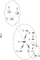
- FIG. 1 is a conceptual diagram illustrating V2X communication scenarios.
- the V2X communications may include Vehicle-to-Vehicle (V2V) communications, Vehicle-to-Infrastructure (V2I) communications, Vehicle-to-Pedestrian (V2P) communications, Vehicle-to-Network (V2N) communications, and the like.
- V2V Vehicle-to-Vehicle
- V2I Vehicle-to-Infrastructure
- V2P Vehicle-to-Pedestrian
- V2N Vehicle-to-Network
- the V2X communications may be supported by a cellular communication system (e.g., a cellular communication system 140), and the V2X communications supported by the cellular communication system 140 may be referred to as "Cellular-V2X (C-V2X) communications.”
- the cellular communication system 140 may include the 4G communication system (e.g., LTE communication system or LTE-A communication system), the 5G communication system (e.g., NR communication system), and the like.
- the V2V communications may include communications between a first vehicle 100 (e.g., a communication node located in the vehicle 100) and a second vehicle 110 (e.g., a communication node located in the vehicle 110).
- Various driving information such as velocity, heading, time, position, and the like may be exchanged between the vehicles 100 and 110 through the V2V communications.
- autonomous driving e.g., platooning
- the V2V communications supported in the cellular communication system 140 may be performed based on "sidelink" communication technologies (e.g., ProSe and D2D communication technologies, and the like). In this case, the communications between the vehicles 100 and 110 may be performed using at least one sidelink channel established between the vehicles 100 and 110.
- the V2I communications may include communications between the first vehicle 100 (e.g., the communication node located in the vehicle 100) and an infrastructure (e.g., road side unit (RSU)) 120 located on a roadside.
- the infrastructure 120 may also include a traffic light or a street light which is located on the roadside.
- the communications may be performed between the communication node located in the first vehicle 100 and a communication node located in a traffic light. Traffic information, driving information, and the like may be exchanged between the first vehicle 100 and the infrastructure 120 through the V2I communications.
- the V2I communications supported in the cellular communication system 140 may also be performed based on sidelink communication technologies (e.g., ProSe and D2D communication technologies, and the like). In this case, the communications between the vehicle 100 and the infrastructure 120 may be performed using at least one sidelink channel established between the vehicle 100 and the infrastructure 120.
- the V2P communications may include communications between the first vehicle 100 (e.g., the communication node located in the vehicle 100) and a person 130 (e.g., a communication node carried by the person 130).
- the driving information of the first vehicle 100 and movement information of the person 130 such as velocity, heading, time, position, and the like may be exchanged between the vehicle 100 and the person 130 through the V2P communications.
- the communication node located in the vehicle 100 or the communication node carried by the person 130 may generate an alarm indicating a danger by judging a dangerous situation based on the obtained driving information and movement information.
- the V2P communications supported in the cellular communication system 140 may be performed based on sidelink communication technologies (e.g., ProSe and D2D communication technologies, and the like). In this case, the communications between the communication node located in the vehicle 100 and the communication node carried by the person 130 may be performed using at least one sidelink channel established between the communication nodes.
- the V2N communications may be communications between the first vehicle 100 (e.g., the communication node located in the vehicle 100) and a server connected through the cellular communication system 140.
- the V2N communications may be performed based on the 4G communication technology (e.g., LTE or LTE-A) or the 5G communication technology (e.g., NR).
- the V2N communications may be performed based on a Wireless Access in Vehicular Environments (WAVE) communication technology or a Wireless Local Area Network (WLAN) communication technology which is defined in Institute of Electrical and Electronics Engineers (IEEE) 802.11, or a Wireless Personal Area Network (WPAN) communication technology defined in IEEE 802.15.
- WAVE Wireless Access in Vehicular Environments
- WLAN Wireless Local Area Network
- IEEE 802.11 Institute of Electrical and Electronics Engineers
- WPAN Wireless Personal Area Network
- the cellular communication system 140 supporting the V2X communications may be configured as follows.
- FIG. 2 is a conceptual diagram illustrating an exemplary embodiment of a cellular communication system.
- a cellular communication system may include an access network, a core network, and the like.
- the access network may include a base station 210, a relay 220, User Equipments (UEs) 231 through 236, and the like.
- the UEs 231 through 236 may include communication nodes located in the vehicles 100 and 110 of FIG. 1 , the communication node located in the infrastructure 120 of FIG. 1 , the communication node carried by the person 130 of FIG. 1 , and the like.
- the core network may include a serving gateway (S-GW) 250, a packet data network (PDN) gateway (P-GW) 260, a mobility management entity (MME) 270, and the like.
- S-GW serving gateway
- PDN packet data network gateway
- MME mobility management entity
- the core network may include a user plane function (UPF) 250, a session management function (SMF) 260, an access and mobility management function (AMF) 270, and the like.
- the core network constituted by the S-GW 250, the P-GW 260, and the MME 270 may support the 5G communication technology as well as the 4G communication technology
- the core network constituted by the UPF 250, the SMF 260, and the AMF 270 may support the 4G communication technology as well as the 5G communication technology.
- the core network may be divided into a plurality of logical network slices.
- a network slice supporting V2X communications e.g., a V2V network slice, a V2I network slice, a V2P network slice, a V2N network slice, etc.
- V2X communications may be supported through the V2X network slice configured in the core network.
- the communication nodes comprising the cellular communication system may perform communications by using at least one communication technology among a code division multiple access (CDMA) technology, a time division multiple access (TDMA) technology, a frequency division multiple access (FDMA) technology, an orthogonal frequency division multiplexing (OFDM) technology, a filtered OFDM technology, an orthogonal frequency division multiple access (OFDMA) technology, a single carrier FDMA (SC-FDMA) technology, a non-orthogonal multiple access (NOMA) technology, a generalized frequency division multiplexing (GFDM) technology, a filter bank multi-carrier (FBMC) technology, a universal filtered multi-carrier (UFMC) technology, and a space division multiple access (SDMA) technology.
- CDMA code division multiple access
- TDMA time division multiple access
- FDMA frequency division multiple access
- OFDM orthogonal frequency division multiplexing
- OFDM orthogonal frequency division multiplexing
- a filtered OFDM technology an orthogonal frequency division multiple access
- the communication nodes comprising the cellular communication system may be configured as follows.
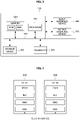
- FIG. 3 is a conceptual diagram illustrating an exemplary embodiment of a communication node constituting a cellular communication system.
- a communication node 300 may comprise at least one processor 310, a memory 320, and a transceiver 330 connected to a network for performing communications. Also, the communication node 300 may further comprise an input interface device 340, an output interface device 350, a storage device 360, and the like. Each component included in the communication node 300 may communicate with each other as connected through a bus 370.
- each of the components included in the communication node 300 may be connected to the processor 310 via a separate interface or a separate bus rather than the common bus 370.
- the processor 310 may be connected to at least one of the memory 320, the transceiver 330, the input interface device 340, the output interface device 350, and the storage device 360 via a dedicated interface.
- the processor 310 may execute at least one instruction stored in at least one of the memory 320 and the storage device 360.
- the processor 310 may refer to a central processing unit (CPU), a graphics processing unit (GPU), or a dedicated processor on which methods in accordance with embodiments of the present disclosure are performed.
- Each of the memory 320 and the storage device 360 may include at least one of a volatile storage medium and a non-volatile storage medium.
- the memory 320 may comprise at least one of read-only memory (ROM) and random access memory (RAM).
- the base station 210 may form a macro cell or a small cell, and may be connected to the core network via an ideal backhaul or a non-ideal backhaul.
- the base station 210 may transmit signals received from the core network to the UEs 231 through 236 and the relay 220, and may transmit signals received from the UEs 231 through 236 and the relay 220 to the core network.
- the UEs 231, 232, 234, 235 and 236 may belong to cell coverage of the base station 210.
- the UEs 231, 232, 234, 235 and 236 may be connected to the base station 210 by performing a connection establishment procedure with the base station 210.
- the UEs 231, 232, 234, 235 and 236 may communicate with the base station 210 after being connected to the base station 210.
- the relay 220 may be connected to the base station 210 and may relay communications between the base station 210 and the UEs 233 and 234. That is, the relay 220 may transmit signals received from the base station 210 to the UEs 233 and 234, and may transmit signals received from the UEs 233 and 234 to the base station 210.
- the UE 234 may belong to both of the cell coverage of the base station 210 and the cell coverage of the relay 220, and the UE 233 may belong to the cell coverage of the relay 220. That is, the UE 233 may be located outside the cell coverage of the base station 210.
- the UEs 233 and 234 may be connected to the relay 220 by performing a connection establishment procedure with the relay 220.
- the UEs 233 and 234 may communicate with the relay 220 after being connected to the relay 220.
- the base station 210 and the relay 220 may support multiple-input, multiple-output (MIMO) technologies (e.g., single user (SU)-MIMO, multi-user (MU)-MIMO, massive MIMO, etc.), coordinated multipoint (CoMP) communication technologies, carrier aggregation (CA) communication technologies, unlicensed band communication technologies (e.g., Licensed Assisted Access (LAA), enhanced LAA (eLAA), etc.), sidelink communication technologies (e.g., ProSe communication technology, D2D communication technology), or the like.
- MIMO multiple-input, multiple-output
- CA carrier aggregation
- LAA Licensed Assisted Access
- eLAA enhanced LAA
- sidelink communication technologies e.g., ProSe communication technology, D2D communication technology
- the UEs 231, 232, 235 and 236 may perform operations corresponding to the base station 210 and operations supported by the base station 210.
- the UEs 233 and 234 may perform operations corresponding to the
- the base station 210 may be referred to as a Node B (NB), an evolved Node B (eNB), a base transceiver station (BTS), a radio remote head (RRH), a transmission reception point (TRP), a radio unit (RU), a roadside unit (RSU), a radio transceiver, an access point, an access node, or the like.
- the relay 220 may be referred to as a small base station, a relay node, or the like.
- Each of the UEs 231 through 236 may be referred to as a terminal, an access terminal, a mobile terminal, a station, a subscriber station, a mobile station, a portable subscriber station, a node, a device, an on-broad unit (OBU), or the like.
- a terminal an access terminal
- a mobile terminal a station
- a subscriber station a mobile station
- a portable subscriber station a node
- a device an on-broad unit (OBU), or the like.
- OBU on-broad unit
- the communications between the UEs 235 and 236 may be performed based on the sidelink communication technique.
- the sidelink communications may be performed based on a one-to-one scheme or a one-to-many scheme.
- V2V communications are performed using the sidelink communication technique
- the UE 235 may be the communication node located in the first vehicle 100 of FIG. 1 and the UE 236 may be the communication node located in the second vehicle 110 of FIG. 1 .
- V2I communications are performed using the sidelink communication technique
- the UE 235 may be the communication node located in first vehicle 100 of FIG. 1 and the UE 236 may be the communication node located in the infrastructure 120 of FIG. 1 .
- V2P communications are performed using the sidelink communication technique
- the UE 235 may be the communication node located in first vehicle 100 of FIG. 1 and the UE 236 may be the communication node carried by the person 130 of FIG. 1 .
- the scenarios to which the sidelink communications are applied may be classified as shown below in Table 1 according to the positions of the UEs (e.g., the UEs 235 and 236) participating in the sidelink communications.
- the scenario for the sidelink communications between the UEs 235 and 236 shown in FIG. 2 may be a sidelink communication scenario C.
- a user plane protocol stack of the UEs (e.g., the UEs 235 and 236) performing sidelink communications may be configured as follows.
- FIG. 4 is a block diagram illustrating an exemplary embodiment of a user plane protocol stack of a UE performing sidelink communication.
- a left UE may be the UE 235 shown in FIG. 2 and a right UE may be the UE 236 shown in FIG. 2 .
- the scenario for the sidelink communications between the UEs 235 and 236 may be one of the sidelink communication scenarios A through D of Table 1.
- the user plane protocol stack of each of the UEs 235 and 236 may comprise a physical (PHY) layer, a medium access control (MAC) layer, a radio link control (RLC) layer, and a packet data convergence protocol (PDCP) layer.
- PHY physical
- MAC medium access control
- RLC radio link control
- PDCP packet data convergence protocol
- the sidelink communications between the UEs 235 and 236 may be performed using a PC5 interface (e.g., PC5-U interface).
- a layer-2 identifier (e.g., a source layer-2 ID, a destination layer-2 ID) may be used for the sidelink communications, and the layer 2-ID may be an ID configured for the V2X communications (e.g., V2X service).
- HARQ hybrid automatic repeat request
- RLC AM RLC acknowledged mode
- RLC UM RLC unacknowledged mode
- a control plane protocol stack of the UEs e.g., the UEs 235 and 236) performing sidelink communications may be configured as follows.
- FIG. 5 is a block diagram illustrating a first exemplary embodiment of a control plane protocol stack of a UE performing sidelink communication
- FIG. 6 is a block diagram illustrating a second exemplary embodiment of a control plane protocol stack of a UE performing sidelink communication.
- a left UE may be the UE 235 shown in FIG. 2 and a right UE may be the UE 236 shown in FIG. 2 .
- the scenario for the sidelink communications between the UEs 235 and 236 may be one of the sidelink communication scenarios A through D of Table 1.
- the control plane protocol stack illustrated in FIG. 5 may be a control plane protocol stack for transmission and reception of broadcast information (e.g., Physical Sidelink Broadcast Channel (PSBCH)).
- PSBCH Physical Sidelink Broadcast Channel
- the control plane protocol stack shown in FIG. 5 may include a PHY layer, a MAC layer, an RLC layer, and a radio resource control (RRC) layer.
- the sidelink communications between the UEs 235 and 236 may be performed using a PC5 interface (e.g., PC5-C interface).
- the control plane protocol stack shown in FIG. 6 may be a control plane protocol stack for one-to-one sidelink communication.
- the control plane protocol stack shown in FIG. 6 may include a PHY layer, a MAC layer, an RLC layer, a PDCP layer, and a PC5 signaling protocol layer.
- channels used in the sidelink communications between the UEs 235 and 236 may include a Physical Sidelink Shared Channel (PSSCH), a Physical Sidelink Control Channel (PSCCH), a Physical Sidelink Discovery Channel (PSDCH), and a Physical Sidelink Broadcast Channel (PSBCH).
- PSSCH may be used for transmitting and receiving sidelink data and may be configured in the UE (e.g., UE 235 or 236) by a higher layer signaling.
- the PSCCH may be used for transmitting and receiving sidelink control information (SCI) and may also be configured in the UE (e.g., UE 235 or 236) by a higher layer signaling.
- SCI sidelink control information
- the PSDCH may be used for a discovery procedure.
- a discovery signal may be transmitted over the PSDCH.
- the PSBCH may be used for transmitting and receiving broadcast information (e.g., system information).
- a demodulation reference signal (DM-RS), a synchronization signal, or the like may be used in the sidelink communications between the UEs 235 and 236.
- the synchronization signal may include a primary sidelink synchronization signal (PSSS) and a secondary sidelink synchronization signal (SSSS).
- a sidelink transmission mode may be classified into sidelink TMs 1 to 4 as shown below in Table 2.
- Sidelink TM Description 1 Transmission using resources scheduled by base station 2 UE autonomous transmission without scheduling of base station 3
- each of the UEs 235 and 236 may perform sidelink communications using a resource pool configured by the base station 210.
- the resource pool may be configured for each of the sidelink control information and the sidelink data.
- the resource pool for the sidelink control information may be configured based on an RRC signaling procedure (e.g., a dedicated RRC signaling procedure, a broadcast RRC signaling procedure).
- the resource pool used for reception of the sidelink control information may be configured by a broadcast RRC signaling procedure.
- the resource pool used for transmission of the sidelink control information may be configured by a dedicated RRC signaling procedure.
- the sidelink control information may be transmitted through resources scheduled by the base station 210 within the resource pool configured by the dedicated RRC signaling procedure.
- the resource pool used for transmission of the sidelink control information may be configured by a dedicated RRC signaling procedure or a broadcast RRC signaling procedure.
- the sidelink control information may be transmitted through resources selected autonomously by the UE (e.g., UE 235 or 236) within the resource pool configured by the dedicated RRC signaling procedure or the broadcast RRC signaling procedure.
- the resource pool for transmitting and receiving sidelink data may not be configured.
- the sidelink data may be transmitted and received through resources scheduled by the base station 210.
- the resource pool for transmitting and receiving sidelink data may be configured by a dedicated RRC signaling procedure or a broadcast RRC signaling procedure.
- the sidelink data may be transmitted and received through resources selected autonomously by the UE (e.g., UE 235 or 236) within the resource pool configured by the dedicated RRC signaling procedure or the broadcast RRC signaling procedure.
- a corresponding second communication node may perform a method (e.g., reception or transmission of the signal) corresponding to the method performed at the first communication node. That is, when an operation of a UE #1 (e.g., vehicle #1) is described, a UE #2 (e.g., vehicle #2) corresponding thereto may perform an operation corresponding to the operation of the UE #1. Conversely, when an operation of the UE #2 is described, the corresponding UE #1 may perform an operation corresponding to the operation of the UE #2.
- an operation of a vehicle may be an operation of a communication node located in the vehicle.
- a HARQ response may indicate acknowledgment (ACK), negative ACK (NACK), and/or discontinuous transmission (DTX).
- ACK acknowledgment
- NACK negative ACK
- DTX discontinuous transmission
- the exemplary embodiment applied to the case where a HARQ response indicates ACK may also be applied to the case where a HARQ response indicates NACK or DTX.
- the exemplary embodiment applied to the case where a HARQ response indicates NACK may also be applied to the case where a HARQ response indicates ACK or DTX.
- the exemplary embodiment applied to the case where a HARQ response indicates DTX may also be applied to the case where a HARQ response indicates ACK or NACK.
- signaling may be one or a combination of two or more of higher layer signaling, MAC signaling, and physical (PHY) signaling.
- a message used for higher layer signaling may be referred to as a 'higher layer message' or 'higher layer signaling message'.
- a message used for MAC signaling may be referred to as a 'MAC message' or 'MAC signaling message'.
- a message used for PHY signaling may be referred to as a 'PHY message' or 'PHY signaling message'.
- the higher layer signaling may refer to an operation of transmitting and receiving system information (e.g., master information block (MIB), system information block (SIB)) and/or an RRC message.
- MIB master information block
- SIB system information block
- the MAC signaling may refer to an operation of transmitting and receiving a MAC control element (CE).
- the PHY signaling may refer to an operation of transmitting and receiving control information (e.g., downlink control information (DCI), uplink control information (UCI), or SCI).
- DCI downlink control information
- UCI uplink control information
- SCI SCI
- a sidelink signal may be a synchronization signal and a reference signal used for sidelink communication.
- the synchronization signal may be a synchronization signal/physical broadcast channel (SS/PBCH) block, sidelink synchronization signal (SLSS), primary sidelink synchronization signal (PSSS), secondary sidelink synchronization signal (SSSS), or the like.
- the reference signal may be a channel state information-reference signal (CSI-RS), DM-RS, phase tracking-reference signal (PT-RS), cell specific reference signal (CRS), sounding reference signal (SRS), discovery reference signal (DRS), or the like.
- a sidelink channel may be a PSSCH, PSCCH, PSDCH, PSBCH, physical sidelink feedback channel (PSFCH), or the like.
- a sidelink channel may refer to a sidelink channel including a sidelink signal mapped to specific resources in the corresponding sidelink channel.
- the sidelink communication may support a broadcast service, a multicast service, a groupcast service, and a unicast service.
- a HARQ feedback operation may be supported.
- a HARQ feedback operation for sidelink-groupcast communication may be performed in two schemes.
- the sidelink-groupcast communication may mean sidelink communication performed in a groupcast scheme.
- all receiving terminals participating in sidelink-groupcast communication e.g., terminals receiving sidelink data
- may share a PSFCH resource region e.g., PSFCH resource pool
- may transmit only NACK to a transmitting terminal e.g., terminal transmitting the sidelink data
- the receiving terminal may not transmit ACK to the transmitting terminal when the sidelink data has been successfully received, and may transmit NACK to the transmitting terminal when the reception of the sidelink data has failed.
- This scheme may be referred to as a 'NACK-only feedback scheme'.
- "data, information, and/or signal is successfully received” may mean that "decoding of the data, information, and/or signal is successful”.
- "reception of data, information, and/or signal fails” may mean “decoding of the data, information, and/or signal fails”.
- a PSFCH resource region may be independently allocated (e.g., configured) to each of the receiving terminals, and each receiving terminal may transmit a HARQ response (e.g., ACK, NACK, or DTX) to the transmitting terminal by using the allocated PSFCH resource region (e.g., dedicated PSFCH resource region).
- a PSFCH may be in form of a sequence.
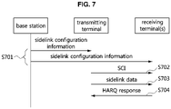
- FIG. 7 is a sequence chart illustrating a first exemplary embodiment of a method for transmitting and receiving HARQ responses in a communication system supporting sidelink communication.
- a communication system may include a base station, a transmitting terminal, and receiving terminal(s).
- the transmitting terminal may be a terminal transmitting sidelink data (e.g., PSSCH), and the receiving terminal(s) may be a terminal receiving the sidelink data.
- the base station may be the base station 210 shown in FIG. 2 .
- the transmitting terminal may be the UE 235 shown in FIG. 2
- the receiving terminal(s) may be the UE 236 shown in FIG. 2 .
- the transmitting terminal may be the UE 236 shown in FIG. 2
- the receiving terminal(s) may be the UE 235 shown in FIG. 2 .
- Each of the transmitting terminal and the receiving terminal(s) may be located in a corresponding vehicle.
- the base station, transmitting terminal, and receiving terminal(s) may be configured identically or similarly to the communication node 300 shown in FIG. 3 .
- the transmitting terminal and receiving terminal(s) may support the protocol stacks shown in FIGS. 4 to 6 .
- the transmitting terminal and receiving terminal(s) may be connected to the base station, and may perform sidelink communication based on scheduling of the base station. Alternatively, the transmitting terminal and receiving terminal(s) may be located outside coverage of the base station, and may perform sidelink communication without scheduling of the base station.
- the base station may generate sidelink configuration information and transmit the sidelink configuration information through higher layer signaling (S701).
- the terminals e.g., transmitting terminal and receiving terminal(s)
- the transmitting terminal and the receiving terminal(s) may perform sidelink-groupcast communication.
- the transmitting terminal may generate SCI including scheduling information (e.g., resource allocation information) of sidelink data (e.g., PSSCH), and may transmit the SCI to the receiving terminal(s) (S702).
- the SCI may include a '1st-stage SCI', or both a '1st-stage SCI' and a '2nd-stage SCI'.
- the SCI (e.g., 1st-stage SCI) may be transmitted on a PSCCH, and the 2nd-stage SCI may be transmitted on a PSSCH.
- the SCI may be a common SCI transmitted to all receiving terminals participating in sidelink-groupcast communication. Alternatively, the SCI may be a dedicated SCI transmitted to each of the receiving terminals participating in sidelink-groupcast communication.
- the 1st-stage SCI may include at least one information element among priority information, frequency resource assignment information, time resource assignment information, resource reservation period information, DMRS pattern information, 2nd-stage SCI format information, beta_offset indicator, the number of DMRS ports, modulation and coding scheme (MCS) information, and combinations thereof.
- the 2nd-stage SCI may include at least one information element among a HARQ processor identifier (ID), redundancy version (RV), source ID, destination ID, CSI request information, zone ID, communication range requirements, and combinations thereof.
- ID HARQ processor identifier
- RV redundancy version
- source ID source ID
- destination ID destination ID
- CSI request information zone ID
- communication range requirements and combinations thereof.
- the SCI may further include information indicating a PSFCH resource for HARQ feedback (e.g., frequency resource assignment information, time resource assignment information) and/or information for transmitting a HARQ feedback.
- a PSFCH resource for HARQ feedback e.g., frequency resource assignment information, time resource assignment information
- the receiving terminal(s) may receive the SCI (e.g., 1st-stage SCI and/or 2nd-stage SCI) from the transmitting terminal, and may identify information elements (e.g., PSSCH resource information, PSFCH resource information, etc.) included in the SCI.
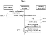
- the transmitting terminal may transmit sidelink data to the receiving terminal(s) on a PSSCH indicated by the SCI (S703).
- the receiving terminal(s) may receive the sidelink data from the transmitting terminal by performing a monitoring operation on the PSSCH.
- Each of the receiving terminal(s) may transmit, to the transmitting terminal, a HARQ response to the sidelink data on a PSFCH indicated by the SCI (S704).
- the PSFCH may be configured by higher layer signaling.
- ACK for the sidelink data may be transmitted in the step S704.
- NACK for the sidelink data may be transmitted in the step S704.
- the NACK-only feedback scheme may be used. In this case, if decoding of the sidelink data is successful, ACK for the sidelink data may not be transmitted in the step S704. If decoding of the sidelink data fails, NACK for the sidelink data may be transmitted in the step S704.
- the transmitting terminal may receive the HARQ response(s) from the receiving terminal(s) by performing a monitoring operation on the PSFCH.
- the transmitting terminal may determine that the sidelink data has been successfully received at the receiving terminal(s).
- the transmitting terminal may determine that reception of the sidelink data has failed at the receiving terminal(s).
- the NACK-only feedback scheme may be used. In this case, if a HARQ response is not received, the transmitting terminal may determine that the sidelink data has been successfully received at the receiving terminal(s). If NACK is received, the transmitting terminal may determine that reception of the sidelink data at the receiving terminal(s) has failed. When it is determined that the receiving terminal(s) has failed to receive the sidelink data, the transmitting terminal may perform a retransmission procedure for the sidelink data.
- One PSFCH (e.g., one PSFCH resource region) may be configured for transmission of HARQ response(s) of the receiving terminal(s).
- the transmitting terminal may distinguish HARQ responses (e.g., ACK or NACK) of a pluarity of receiving terminals based on PSFCHs (e.g., feedback resource region belonging to the PSFCH) allocated the respective receiving terminals and/or sequences configured for the respective receiving terminals.
- the sequences (e.g., sequences mapped to the HARQ responses) used by the receiving terminals for transmission of the HARQ responses may be orthogonal sequences.
- a receiving terminal #1 may transmit a HARQ response using a sequence #1
- a receiving terminal #2 may transmit a HARQ response using a sequence #2.
- the operation of transmitting a HARQ response using a sequence may mean an operation of transmitting the sequence mapped to the HARQ response.
- the sequence #1 may be orthogonal to the sequence #2.
- One PSFCH on which HARQ response(s) are transmitted/received may be configured with a plurality of feedback resource regions.
- the PSFCH (e.g., PSFCH resource region) may be configured as follows.
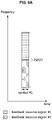
- FIG. 8A is a conceptual diagram illustrating a first exemplary embodiment of a PSFCH including one or more feedback resource regions in a communication system supporting sidelink communication
- FIG. 8B is a conceptual diagram illustrating a second exemplary embodiment of a PSFCH including one or more feedback resource regions in a communication system supporting sidelink communication
- FIG. 8C is a conceptual diagram illustrating a third exemplary embodiment of a PSFCH including one or more feedback resource regions in a communication system supporting sidelink communication.
- one PSFCH may include feedback resource regions #1 and #2.
- the PSFCH may be configured in one or more resource blocks (RBs) in the frequency domain, and may be configured in one or more symbols in the time domain.
- RBs resource blocks
- the PSFCH may be configured in one symbol in the time domain, and the feedback resource region #1 may be multiplexed with the feedback resource region #2 in the frequency domain.
- the PSFCH may be configured in two symbols in the time domain, and the feedback resource region #1 may be multiplexed with the feedback resource region #2 in the frequency domain.
- the PSFCH may be configured in two symbols in the time domain, and the feedback resource region #1 may be multiplexed with the feedback resource region #2 in the time domain.
- the feedback resource region #1 may be arranged in a symbol #1, and the feedback resource region #2 may be arranged in a symbol #2.
- the feedback resource region #1 may be arranged in the symbol #2, and the feedback resource region #2 may be arranged in the symbol #1.
- a HARQ response may be transmitted/received based on an 'ACK/NACK feedback scheme' or a 'NACK-only feedback scheme'.
- the ACK/NACK feedback scheme the number of feedback resource regions included in one PSFCH is n, and the number of sequences (e.g., orthogonal sequences) usable in one feedback resource region is m, the transmitting terminal may be able to distinguish HARQ responses (e.g., ACK or NACK) received from n ⁇ m 2 receiving terminals in one PSFCH.
- m sequences (e.g., a maximum of m sequences) are usable in one feedback resource region” may mean “the transmitting terminal is able to identify each of m sequences received in the same physical resource region (e.g., one feedback resource region)".
- the operation of discriminating the sequences may include an operation of identifying whether a HARQ response mapped to each sequence is ACK or NACK, and an operation of identifying a receiving terminal transmitting the HARQ response mapped to the sequence.
- a PSFCH may include two feedback resource regions, and a maximum of eight sequences (e.g., orthogonal sequences) may be used in one feedback resource region.
- the maximum number of receiving terminals that the transmitting terminal can distinguish in the same feedback resource region may be four. That is, when four receiving terminals transmit HARQ responses (e.g., ACK or NACK) in the same feedback resource region, the transmitting terminal may be able to identify whether a HARQ response received from each of the four receiving terminals is ACK or NACK.
- the eight sequences may be reused in different feedback resource regions.
- the transmitting terminal may identify whether a HARQ response received from each of up to eight receiving terminals in one PSFCH is ACK or NACK.
- feedback resource regions and sequences allocated to the respective receiving terminals may be as shown in Table 3 below.
- the exemplary embodiment described in Table 3 below may be referred to as a 'sequence pattern #1'.
- the operation of allocating the feedback resource regions and sequences may be performed through one or a combination of two or more of higher layer signaling, MAC signaling, and PHY signaling.
- sequences may be used to identify ACKs for the respective receiving terminals, and one sequence may be used for NACKs of a plurality of receiving terminals. That is, the sequence for NACK may be used to identify NACK from among ACK and NACK, and may not be used to identify NACK for each receiving terminal.
- the feedback resource regions and sequences allocated to the respective receiving terminals may be as shown in Table 4 below. The exemplary embodiment described in Table 4 may be referred to as a 'sequence pattern #2'.
- the operation of allocating the feedback resource regions and sequences may be performed through one or a combination of two or more of higher layer signaling, MAC signaling, and PHY signaling.
- a sequence #1 may be used to identify NACK from among ACK and NACK, and sequences #2 to #8 may be used to identify ACKs for the respective receiving terminals.
- the transmitting terminal in one feedback resource region, the transmitting terminal may be able to identify ACK received from each of up to seven receiving terminals.
- the transmitting terminal In the PSFCH including two feedback resource regions, the transmitting terminal may be able to identify ACK received from each of up to fourteen receiving terminals.
- the sequence #1 e.g., NACK
- the transmitting terminal may determine that one or more receiving terminals (e.g., one or more receiving terminals excluding receiving terminal(s) having transmitted ACK among a plurality of receiving terminals) have transmitted NACK.
- one feedback resource region (e.g., feedback resource region #1) among a plurality of feedback resource regions included in one PSFCH may be used for transmission and reception of ACK, and another feedback resource region (e.g., feedback resource region #2) may be used for transmission and reception of NACK.
- Sequences #1 to #8 in the feedback resource region #1 may be used to identify ACKs for the respective receiving terminals, and one sequence (e.g., any sequence, arbitrary sequence, or specific sequence) may be used to detect NACK in the feedback resource region #2.
- feedback resource regions and sequences allocated to the respective receiving terminals may be as shown in Table 5 below.
- the exemplary embodiment described in Table 5 below may be referred to as a 'sequence pattern #3'.
- the operation of allocating the feedback resource regions and sequences may be performed through one or a combination of two or more of higher layer signaling, MAC signaling, and PHY signaling.
- the transmitting terminal may identify ACK received from each of up to eight receiving terminals in the feedback resource region #1, and may identify whether NACK is received by performing an energy detection operation or a sequence detection operation on the feedback resource region #2.
- the transmitting terminal may identify ACK received from each of up to eight receiving terminals in the feedback resource region #1, and may identify whether NACK is received by performing an energy detection operation or a sequence detection operation on the feedback resource region #2.
- by performing an energy detection operation instead of a sequence detection operation it may be identified whether NACK is received.
- an energy detection operation cannot be performed, and whether NACK is received may be identified by performing a sequence detection operation.
- the reception performance according to the exemplary embodiment shown in Table 5 can be improved than the reception performance according to the exemplary embodiment shown in Table 4, and the reception complexity according to the exemplary embodiment shown in Table 5 may be reduced than the reception complexity according to the exemplary embodiment shown in Table 4.
- one PSFCH includes two feedback resource regions, and eight sequences are usable in one feedback resource region
- the feedback resource regions and sequences allocated to the respective receiving terminals may be as shown in Table 6 below.
- the exemplary embodiment described in Table 6 below may be referred to as a 'sequence pattern #4'.
- the operation of allocating the feedback resource regions and sequences may be performed through one or a combination of two or more of higher layer signaling, MAC signaling, and PHY signaling.
- sequences #1 to #8 may be used to identify NACKs for the respective receiving terminals.
- the transmitting terminal may be able to identify NACK received from each of up to eight receiving terminals in one feedback resource region, and may identify NACK received from each of up to sixteen receiving terminals in the PSFCH including two feedback resource regions.
- one sequence may be used for NACKs of all receiving terminals. That is, one sequence mapped to NACKs of all receiving terminals may be configured.
- the feedback resource regions and sequences allocated to the respective receiving terminals may be as shown in Table 7 below.
- the exemplary embodiment shown in Table 7 below may be referred to as a 'sequence pattern #5'.
- the operation of allocating the feedback resource regions and sequences may be performed through one or a combination of two or more of higher layer signaling, MAC signaling, and PHY signaling.
- the transmitting terminal may identify whether NACK is received by performing an energy detection operation or a sequence detection operation on the feedback resource region #1 (or PSFCH).
- the transmitting terminal may determine that NACK has been transmitted from one or more receiving terminals.
- sequence patterns #1 to #5 may be one of exemplary embodiments applied to the present disclosure, and sequence pattern(s) modified based on the above-described sequence patterns #1 to #5 may also be applied to the present disclosure.
- sidelink communication e.g., sidelink-groupcast communication
- sidelink-groupcast communication may be performed based on the above-described 'PSFCH structure' and 'sequence-based HARQ response transmission method'.
- FIG. 9 is a sequence chart illustrating a second exemplary embodiment of a method for transmitting and receiving HARQ responses in a communication system supporting sidelink communication.
- a communication system may include a base station, a transmitting terminal, and receiving terminal(s).
- the transmitting terminal may be a terminal transmitting sidelink data (e.g., PSSCH), and the receiving terminal(s) may be terminal(s) receiving the sidelink data.
- the base station may be the base station 210 shown in FIG. 2 .
- the transmitting terminal may be the UE 235 shown in FIG. 2
- the receiving terminal(s) may be the UE 236 shown in FIG. 2 .
- the transmitting terminal may be the UE 236 shown in FIG. 2
- the receiving terminal(s) may be the UE 235 shown in FIG. 2 .
- Each of the transmitting terminal and receiving terminal(s) may be located in a corresponding vehicle.
- the base station, transmitting terminal, and receiving terminal(s) may be configured identically or similarly to the communication node 300 shown in FIG. 3 .
- the transmitting terminal and receiving terminal(s) may support the protocol stacks shown in FIGS. 4 to 6 .
- the transmitting terminal and receiving terminal(s) may be connected to the base station, and may perform sidelink communication based on scheduling of the base station. Alternatively, the transmitting terminal and receiving terminal(s) may be located outside coverage of the base station, and may perform sidelink communication without scheduling of the base station.
- the base station may generate sidelink configuration information and transmit the sidelink configuration information through higher layer signaling (S901).
- the sidelink configuration information may include PSFCH configuration information (e.g., SL-PSFCH-Config).
- the PSFCH configuration information may include one or more information elements among information elements shown in Table 8 below.
- the sidelink configuration information may include PSFCH configuration information #1 for the PSFCH #1 and PSFCH configuration information #2 for the PSFCH #2.
- PSFCH When the number of terminals (e.g., receiving terminals) participating in sidelink communication (e.g., sidelink-groupcast communication) is less than or equal to a threshold, one PSFCH (e.g., PSFCH #1) may be used, and when the number of terminals participating in sidelink communication exceeds a threshold, a plurality of PSFCHs (e.g., PSFCHs #1 and #2) may be used.
- Each of the PSFCH configuration information #1 and the PSFCH configuration information #2 may include one or more information elements among information elements shown in Table 8 below.
- Information element Description sl-PSFCH-Period sl-PSFCH-Period may indicate a period of a PSFCH resource region within a resource pool.
- sl-PSFCH-Period may be set in units of slots.
- sl-PSFCH_Duration sl-PSFCH-Duration may indicate a length of a PSFCH resource region in the time domain.
- sl-PSFCH-Duration may be set in units of symbols. For example, sl-PSFCH-Duration may indicate one, two, three, or four symbols.
- sl-PSFCH-RB-Set sl-PSFCH-RB-Set may indicate a set of PRBs (e.g., the number of PRBs included in the set of PRBs) of a PSFCH resource region used for transmitting and receiving PSFCH(s).
- the set of PRBs may include one or more PRBs (e.g., RBs).
- sl-Feedback-RB-Setl sl-Feedback-RB-Setl may indicate a set of PRBs (e.g., the number of PRBs included in the set of PRBs) of a feedback resource region #1 included in a PSFCH resource region.
- the set of PRBs may include one or more PRBs (e.g., RBs).
- sl-Feedback-RB-Set2 sl-Feedback-RB-Setl may indicate a set of PRBs (e.g., the number of PRBs included in the set of PRBs) of a feedback resource region #2 included in a PSFCH resource region.
- the set of PRBs may include one or more PRBs (e.g., RBs).
- sl-Feedback-Sym1 sl-Feedback-Sym1 may indicate the number and/or index(es) of symbol(s) in which a feedback resource region #1 is disposed, when a PSFCH resource region is configured with a plurality of symbols.
- sl-Feedback-Sym2 sl-Feedback-Sym2 may indicate the number and/or index(es) of symbol(s) in which a feedback resource region #2 is disposed, when a PSFCH resource region is configured with a plurality of symbols.
- the PSFCH configuration information may include configuration information (e.g., sl-Feedback-RB-Set1, sl-Feedback-Sym1) of one feedback resource region.
- the PSFCH configuration information may include configuration information (e.g., sl-Feedback-RB-Setl, sl-Feedback-Sym1, sl-Feedback-RB-Set2, sl-Feedback-Sym2) of the plurality of feedback resource regions.
- the PSFCH configuration information may further include configuration information on a HARQ feedback scheme.
- the HARQ feedback scheme may include the ACK/NACK feedback scheme and the NACK-only feedback scheme. In sidelink-groupcast communication, an appropriate HARQ feedback scheme may be used according to various requirements.
- the configuration information on the HARQ feedback scheme may be configured as shown in Table 9 or Table 10 below. [Table 9] Information element Description sl-HARQ-Typel sl-HARQ-Typel may indicate whether the ACK/NACK feedback scheme is used. sl-HARQ-Typel set to 0 may indicate that the ACK/NACK feedback scheme is not used. sl-HARQ-Typel set to 1 may indicate that the ACK/NACK feedback scheme can be used.
- sl-HARQ-Type2 sl-HARQ-Type2 may indicate whether the NACK-only feedback scheme is used. sl-HARQ-Type2 set to 0 may indicate that the NACK-only feedback scheme is not used. sl-HARQ-Type2 set to 1 may indicate that the NACK-only feedback scheme can be used.
- the HARQ feedback scheme (e.g., ACK/NACK feedback scheme or NACK-only feedback scheme) configured by higher layer signaling may be used in sidelink communication.
- the HARQ feedback scheme applied to sidelink communication may be indicated by higher layer signaling (e.g., a higher layer signaling message different from the higher layer signaling message indicating Table 9), MAC signaling, and/or PHY signaling.
- sl-Default-HARQ-Type may indicate a default HARQ feedback scheme or a current HARQ feedback scheme.
- sl- Default-HARQ-Type set to 0 may indicate the ACK/NACK feedback scheme.
- sl-Default-HARQ-Type set to 1 may indicate the NACK-only feedback scheme.
- Sidelink communication may be performed based on a HARQ feedback scheme indicated by sl-Default-HARQ-Type.
- Maintenance or change of the HARQ feedback scheme configured the by higher layer signaling may be indicated by higher layer signaling (e.g., a higher layer signaling message different from the higher layer signaling message indicating Table 10), MAC signaling, and/or PHY signaling.
- higher layer signaling e.g., a higher layer signaling message different from the higher layer signaling message indicating Table 10
- MAC signaling e.g., a higher layer signaling message different from the higher layer signaling message indicating Table 10
- MAC signaling e.g., MAC signaling message different from the higher layer signaling message indicating Table 10
- PHY signaling e.g., PHY signaling.
- a toggle bit included in an RRC message, MAC CE, or control information e.g., DCI or SCI
- toggle bit included in the RRC message, MAC CE, or control information (e.g., DCI or SCI) is set to 1, this may indicate that the HARQ feedback scheme configured by the higher layer signaling (e.g., sl-Default-HARQ-Type) is to be changed.
- the HARQ feedback scheme configured by the higher layer signaling is the ACK/NACK feedback scheme and the toggle bit included in the RRC message, MAC CE, or control information is set to 1
- the HARQ feedback scheme may be changed from the ACK/NACK feedback scheme to the NACK-only feedback scheme.
- the HARQ feedback scheme configured by the higher layer signaling is the NACK-only feedback scheme, and the toggle bit included in the RRC message, MAC CE, or control information is set to 1
- the HARQ feedback scheme may be changed from the NACK-only feedback scheme to the ACK/NACK feedback scheme.
- the PSFCH configuration information may further include sequence pattern configuration information.
- the sequence pattern configuration information may include one or more information elements described in Table 11 below. [Table 11] Information element Description sl-Maxnum-Sequence sl-Maxum-Sequence may indicate the maximum number of sequences in usable in a PSFCH resource region (or, feedback resource region). sl-Sequence-Pattern sl-Sequence-Pattern may indicate sequence pattern candidates used for HARQ response transmission or one sequence pattern.
- sl-Sequence-Pattern may indicate ⁇ sequence pattern #1, sequence pattern #2, sequence pattern #3, sequence pattern #4, sequence pattern #5 ⁇ as sequence pattern candidates.
- the sequence pattern #1 may be the sequence pattern described in Table 3 above
- the sequence pattern #2 may be the sequence pattern described in Table 4 above
- the sequence pattern #3 may be the sequence pattern described in Table 5 above.
- the sequence pattern #4 may be the sequence pattern described in Table 6 above
- the sequence pattern #5 may be the sequence pattern described in Table 7 above.
- one sequence pattern used in sidelink communication may be indicated by higher layer signaling (e.g., a higher layer signaling message different from the higher layer signaling message indicating the sequence pattern candidates), MAC signaling, and/or PHY signaling.
- higher layer signaling e.g., a higher layer signaling message different from the higher layer signaling message indicating the sequence pattern candidates
- MAC signaling e.g., a higher layer signaling message different from the higher layer signaling message indicating the sequence pattern candidates
- PHY signaling e.g., PHY signaling
- one specific sequence pattern may be indicated by higher layer signaling.
- the sidelink communication may be performed using the sequence pattern indicated by the higher layer signaling.
- the information element(s) shown in Tables 8 to 11 may be transmitted through one or a combination of two or more of higher layer signaling, MAC signaling, and PHY signaling. The information element(s) listed in Tables 8 to 11 may be indicated implicitly or explicitly.
- the transmitting terminal and/or the receiving terminal(s) may receive the higher layer message from the base station, and may identify the sidelink configuration information (e.g., PSFCH configuration information) included in the higher layer message.
- the PSFCH configuration information may include one or more information elements listed in Tables 8 to 11.
- the transmitting terminal and/or the receiving terminal(s) may perform sidelink communication (e.g., sidelink-groupcast communication) using the sidelink configuration information.
- the transmitting terminal may generate SCI (e.g., 1st-stage SCI and/or 2nd-stage SCI) including scheduling information for transmission of sidelink data, and transmit the SCI to the receiving terminal(s) (S902).
- SCI may be transmitted on a PSCCH and/or PSSCH.
- the SCI may be a common SCI transmitted to all receiving terminals participating in sidelink-groupcast communication.
- the SCI may be a dedicated SCI transmitted to each of the receiving terminals participating in sidelink-groupcast communication.
- the SCI may further include PSFCH resource information for HARQ feedback transmission for sidelink data as well as the scheduling information.
- the SCI may further include one or more information elements listed in Table 12 below.
- PSFCH1-UE-id may be information (e.g., terminal IDs, terminal indexes, group ID, group index) indicating terminals using a PSFCH #1 when a plurality of PSFCHs are configured.
- PSFCH2-UE-id PSFCH2-UE-id may be information (e.g., terminal IDs, terminal indexes, group ID, group index) indicating terminals using a PSFCH #2 when a plurality of PSFCHs are configured.
- Feedbackl-UE-id Feedbackl-UE-id may be information (e.g., terminal IDs, terminal indexes, group ID, group index) indicating terminals using a feedback resource region #1 when one PSFCH includes a plurality of feedback resource regions.
- Feedback2-UE-id Feedback2-UE-id may be information (e.g., terminal IDs, terminal indexes, group ID, group index) indicating terminals using a feedback resource region #2 when one PSFCH includes a plurality of feedback resource regions.
- HARQ-indicator HARQ-indicator may indicate a HARQ feedback scheme used for sidelink communication.
- HARQ-toggle HARQ-toggle may indicate whether a HARQ feedback scheme used for sidelink communication is changed.
- SequencePattern-indicator may indicate a sequence pattern used for sidelink communication. Sequence-indicator Sequence-indicator may indicate sequences allocated to respective terminals. When Sequence-indicator is not present, the terminals may generate sequences according to a rule (e.g., equation) that the terminals know, and the generated sequences may be orthogonal to each other.
- a rule e.g., equation
- the receiving terminal(s) may receive SCI from the transmitting terminal, and may identify information element(s) included in the SCI.
- the transmitting terminal may transmit sidelink data on a PSSCH indicated by the SCI (S903).
- the sidelink data may be transmitted to one or more receiving terminals in a groupcast scheme.
- the receiving terminal(s) may perform a monitoring operation on the PSSCH indicated by the SCI to obtain the sidelink data.
- the receiving terminal(s) may transmit HARQ response(s) to the transmitting terminal based on result(s) of receiving the sidelink data (S904).
- Sequence(s) mapped to the HARQ response(s) in the step S904 may be transmitted on a PSFCH (e.g., feedback resource region).
- the step S904 may be performed as follows.
- a PSFCH #1 may be one PSFCH among the one or more PSFCHs.
- the feedback resource region #1 may be one feedback resource region among the one or more feedback resource regions.
- the receiving terminal #1 may successfully receive the sidelink data from the transmitting terminal, and the receiving terminal #2 may fail to receive the sidelink data.
- the receiving terminal #1 may transmit the sequence #1 mapped to ACK to the transmitting terminal through the feedback resource region #1 within the PSFCH #1 (S904), and the receiving terminal #2 may transmit the sequence #4 mapped to NACK to the transmitting terminal through the feedback resource region #1 within the PSFCH #1 (S904). That is, ACK (e.g., sequence #1) of the receiving terminal #1 and NACK (e.g., sequence #4) of the receiving terminal #2 may be transmitted using the same feedback resource region.
- the transmitting terminal knows the configuration of the information elements shown in Table 13, and may perform a monitoring operation on the feedback resource region #1 within the PSFCH #1 in order to receive the HARQ responses of the receiving terminals #1 and #2. Since the sequence #1 is orthogonal to the sequence #4, the transmitting terminal may detect the sequences #1 and #4 in the feedback resource region #1 within the PSFCH #1. Accordingly, the transmitting terminal may determine that decoding of the sidelink data is successful in the receiving terminal #1, and may determine that the decoding of the sidelink data in the receiving terminal #2 has failed.
- a PSFCH #1 may be one PSFCH among the one or more PSFCHs.
- a feedback resource region #1 may be one feedback resource region among the one or more feedback resource regions.
- HARQ feedback scheme PSFCH Feedback resource region Sequence pattern Sequence Receiving terminal #1 ACK/NACK feedback scheme PSFCH #1 Feedback resource region #1 Sequence pattern #2 ACK Sequence #2 NACK Sequence #1 Receiving terminal #2 ACK/NACK feedback scheme PSFCH #1 Feedback resource region #1 Sequence pattern #2 ACK Sequence #3 NACK Sequence #1
- the receiving terminal #1 may successfully receive sidelink data from the transmitting terminal, and the receiving terminal #2 may fail to receive the sidelink data.
- the receiving terminal #1 may transmit the sequence #2 mapped to ACK to the transmitting terminal through the feedback resource region #1 within the PSFCH #1 (S904), and the receiving terminal #2 may transmit the sequence #1 mapped to NACK to the transmitting terminal through the feedback resource region #1 within the PSFCH #1 (S904). That is, ACK (e.g., sequence #2) of the receiving terminal #1 and NACK (e.g., sequence #1) of the receiving terminal #2 may be transmitted using the same feedback resource region.
- the transmitting terminal knows the configuration of the information elements shown in Table 14, and may perform a monitoring operation on the feedback resource region #1 within the PSFCH #1 in order to receive the HARQ responses of the receiving terminals #1 and #2. Since the sequence #1 is orthogonal to the sequence #2, the transmitting terminal may detect the sequences #1 and #2 in the feedback resource region #1 within the PSFCH #1. Accordingly, the transmitting terminal may determine that decoding of the sidelink data is successful in the receiving terminal #1, and may determine that decoding of the sidelink data in one or more receiving terminals has failed.
- the one or more receiving terminals may be one or more receiving terminals excluding the receiving terminal #1 that has transmitted ACK among a plurality of receiving terminals using the feedback resource region #1 within the PSFCH #1.
- PSFCHs #1 and #2 may be configured, and each PSFCH may include a plurality of feedback resource regions (e.g., feedback resource regions #1 and #2).
- HARQ feedback scheme PSFCH Feedback resource region Sequence pattern Sequence Receiving terminal #1 ACK/NACK feedback scheme PSFCH #1 Feedback resource regions #1 and #2 Sequence pattern #3 ACK Sequence #1 NACK Arbitrary sequence Receiving terminal #2 ACK/NACK feedback scheme PSFCH #2 Feedback resource regions #1 and #2 Sequence pattern #3 ACK Sequence #2 NACK Arbitrary sequence
- the receiving terminal #1 may successfully receive sidelink data from the transmitting terminal, and the receiving terminal #2 may fail to receive the sidelink data.
- the receiving terminal #1 may transmit the sequence #1 mapped to ACK to the transmitting terminal through the feedback resource region #1 within the PSFCH #1 (S904), and the receiving terminal #2 may transmit an arbitrary sequence mapped to NACK to the transmitting terminal through the feedback resource region #2 within the PSFCH #2 (S904).
- the transmitting terminal knows the configuration of the information elements described in Table 15, and may perform a monitoring operation on the PSFCH #1 to receive the HARQ response of the receiving terminal #1, and may perform a monitoring operation on the PSFCH #2 to receive the HARQ response of the receiving terminal #2.
- the transmitting terminal may detect the sequence #1 in the feedback resource region #1 within the PSFCH #1, and may detect an arbitrary sequence in the feedback resource region #2 within the PSFCH #2.
- the transmitting terminal may determine that decoding of the sidelink data is successful in the receiving terminal #1 among one or more receiving terminals using the PSFCH #1, and may determine that decoding of the sidelink data has failed in one or more receiving terminals (excluding the receiving terminal(s) that have transmitted ACK among a plurality of receiving terminals).
- a PSFCH #1 may be one PSFCH among the one or more PSFCHs.
- a feedback resource region #1 may be one feedback resource region among the one or more feedback resource regions.
- the receiving terminal #1 may successfully receive sidelink data from the transmitting terminal, and the receiving terminal #2 may fail to receive the sidelink data. In this case, the receiving terminal #1 may not transmit a HARQ response (e.g., ACK) to the transmitting terminal, and the receiving terminal #2 may transmit the sequence #2 mapped to NACK to the transmitting terminal through the feedback resource region #1 within the PSFCH #1 (S904).
- a HARQ response e.g., ACK
- the transmitting terminal knows the configuration of the information elements described in Table 16, and in order to receive the HARQ responses (e.g., NACK) of the receiving terminals #1 and #2, may perform a monitoring operation on the feedback resource region #1 within the PSFCH #1.
- the sequence #1 may be orthogonal to sequence #2, and even when the sequences #1 and #2 are transmitted through the same feedback resource region, the transmitting terminal may distinguish between the sequence #1 and the sequence #2 from among detected sequences.
- the transmitting terminal may detect the sequence #2 in the feedback resource region #1 within the PSFCH #1. Accordingly, the transmitting terminal may determine that decoding of the sidelink data in the receiving terminal #2 has failed. When the sequence #1 is not detected in the feedback resource region #1 within the PSFCH #1, the transmitting terminal may determine that the decoding of the sidelink data is successful in the receiving terminal #1.
- a PSFCH #1 may be one PSFCH among the one or more PSFCHs.
- the feedback resource region #1 may be one feedback resource region among the one or more feedback resource regions.
- the receiving terminal #1 may successfully receive sidelink data from the transmitting terminal, and the receiving terminal #2 may fail to receive the sidelink data. In this case, the receiving terminal #1 may not transmit a HARQ response (e.g., ACK) to the transmitting terminal, and the receiving terminal #2 may transmit the sequence #1 mapped to NACK to the transmitting terminal through the feedback resource region #1 within the PSFCH #1 (S904).
- a HARQ response e.g., ACK
- the transmitting terminal knows the configuration of the information elements described in Table 17, and in order to receive the HARQ responses (e.g., NACK) of the receiving terminals #1 and #2, may perform a monitoring operation on the feedback resource region #1 within the PSFCH #1.
- the transmitting terminal may detect the sequence #1 in the feedback resource region #1 within the PSFCH #1. Accordingly, the transmitting terminal may determine that decoding of the sidelink data has failed in one or more terminals among a plurality of receiving terminals using the feedback resource region #1 within the PSFCH #1.
- an MCS level may be changed in a retransmission procedure of the sidelink data.
- the sidelink retransmission procedure for (k-i) receiving terminals may be performed. That is, the (k-i) receiving terminals may be receiving terminals that have transmitted NACK (e.g., sequence mapped to NACK) in the initial transmission procedure of the sidelink data.
- each of k and i may be an integer of 1 or more, and k may be greater than i.
- the MCS level may be changed based on the worst channel state information (CSI) among CSI(s) of the (k-i) receiving terminals. Accordingly, the size of a PSSCH resource region used for retransmission of the sidelink data may be changed.
- the transmitting terminal may transmit SCI including scheduling information (e.g., resource allocation information) for retransmission sidelink data on a PSCCH and/or PSSCH.
- the scheduling information for the retransmission sidelink data may include information indicating the changed MCS level.
- a PSFCH resource region (e.g., feedback resource region) for HARQ feedback for the retransmission sidelink data may be configured in consideration of the (k-i) receiving terminals excluding i receiving terminals that have transmitted ACK among k receiving terminals (i.e., all receiving terminals).
- a sequence for the (k-i) receiving terminals may be reconfigured.
- the size of the PSFCH resource region for HARQ feedback for the retransmission sidelink data may be configured to be smaller than the PSFCH resource region for HARQ feedback for the initial transmission sidelink data.
- Resources, sequences, and/or specific signals used respectively by the (k-i) receiving terminals may be newly configured.
- the exemplary embodiments of the present disclosure may be implemented as program instructions executable by a variety of computers and recorded on a computer readable medium.
- the computer readable medium may include a program instruction, a data file, a data structure, or a combination thereof.
- the program instructions recorded on the computer readable medium may be designed and configured specifically for the present disclosure or can be publicly known and available to those who are skilled in the field of computer software.
- Examples of the computer readable medium may include a hardware device such as ROM, RAM, and flash memory, which are specifically configured to store and execute the program instructions.
- Examples of the program instructions include machine codes made by, for example, a compiler, as well as high-level language codes executable by a computer, using an interpreter.
- the above exemplary hardware device can be configured to operate as at least one software module in order to perform the embodiments of the present disclosure, and vice versa.
Landscapes
- Engineering & Computer Science (AREA)
- Signal Processing (AREA)
- Computer Networks & Wireless Communication (AREA)
- Mobile Radio Communication Systems (AREA)
Applications Claiming Priority (2)
| Application Number | Priority Date | Filing Date | Title |
|---|---|---|---|
| US201962886634P | 2019-08-14 | 2019-08-14 | |
| PCT/KR2020/009664 WO2021029557A1 (ko) | 2019-08-14 | 2020-07-22 | 사이드링크 통신을 지원하는 통신 시스템에서 harq 응답의 송수신을 위한 방법 및 장치 |
Publications (2)
| Publication Number | Publication Date |
|---|---|
| EP3998728A1 true EP3998728A1 (de) | 2022-05-18 |
| EP3998728A4 EP3998728A4 (de) | 2023-08-16 |
Family
ID=74570636
Family Applications (1)
| Application Number | Title | Priority Date | Filing Date |
|---|---|---|---|
| EP20852007.2A Pending EP3998728A4 (de) | 2019-08-14 | 2020-07-22 | Verfahren und vorrichtung zum senden und empfangen von harq-antworten in einem drahtlosen kommunikationssystem mit sidelink-kommunikationsunterstützung |
Country Status (5)
| Country | Link |
|---|---|
| US (2) | US12446024B2 (de) |
| EP (1) | EP3998728A4 (de) |
| KR (1) | KR20210020773A (de) |
| CN (2) | CN119070958A (de) |
| WO (1) | WO2021029557A1 (de) |
Cited By (2)
| Publication number | Priority date | Publication date | Assignee | Title |
|---|---|---|---|---|
| WO2024077138A1 (en) * | 2022-10-05 | 2024-04-11 | Interdigital Patent Holdings, Inc. | Methods and systems of sidelink operations for beam-based mode 2 harq in shared spectrum |
| EP4369644A4 (de) * | 2021-07-06 | 2025-06-11 | LG Electronics Inc. | Verfahren und vorrichtung zur partiellen erfassung auf der basis von sl-harq-rückkopplung in nr v2x |
Families Citing this family (10)
| Publication number | Priority date | Publication date | Assignee | Title |
|---|---|---|---|---|
| CN112152760B (zh) * | 2019-06-27 | 2022-03-29 | 华为技术有限公司 | 一种psfch的发送方法及装置 |
| CN112399588B (zh) * | 2019-08-16 | 2024-08-13 | 华为技术有限公司 | 用于传输混合自动重传请求harq反馈信息的方法和装置 |
| US20210067290A1 (en) * | 2019-08-26 | 2021-03-04 | Mediatek Singapore Pte. Ltd. | Sidelink communications with two-stage sidelink control information |
| CN115051779A (zh) * | 2019-10-12 | 2022-09-13 | 华为技术有限公司 | 通信方法及装置 |
| US12438649B2 (en) * | 2019-11-05 | 2025-10-07 | Qualcomm Incorporated | Sidelink identification for multi-path downlink retransmission |
| JP7398002B2 (ja) * | 2020-02-14 | 2023-12-13 | 北京小米移動軟件有限公司 | フィードバック方式の指示及び決定方法、装置、記憶媒体 |
| CN113766640B (zh) * | 2020-06-01 | 2024-11-19 | 华为技术有限公司 | 通信方法及装置 |
| EP4187967A4 (de) * | 2020-09-08 | 2024-01-24 | LG Electronics Inc. | Verfahren und vorrichtung für sidelink-drx-timer-basierten energiesparenden endgerät in nr v2x |
| CN115549866A (zh) * | 2021-06-30 | 2022-12-30 | 华为技术有限公司 | 侧行链路反馈信息传输的方法和通信装置 |
| US20250294582A1 (en) * | 2022-04-24 | 2025-09-18 | Lenovo (Beijing) Limited | Methods and apparatuses for sidelink feedback resource allocation |
Family Cites Families (22)
| Publication number | Priority date | Publication date | Assignee | Title |
|---|---|---|---|---|
| CN102098151B (zh) * | 2010-12-28 | 2015-08-12 | 中兴通讯股份有限公司 | 一种正确/错误应答消息的发送方法及用户终端 |
| CN103973413B (zh) * | 2013-02-01 | 2017-04-12 | 电信科学技术研究院 | 一种传输反馈信息的方法、设备及系统 |
| WO2017026973A1 (en) * | 2015-08-12 | 2017-02-16 | Intel Corporation | Resource access in device to device communication |
| US10334586B2 (en) * | 2016-01-22 | 2019-06-25 | Qualcomm Incorporated | Hybrid automatic repeat request feedback for unicast sidelink communications |
| WO2018048273A1 (ko) | 2016-09-11 | 2018-03-15 | 엘지전자 주식회사 | 무선 통신 시스템에서 v2x 통신을 위한 신호 전송 방법 및 이를 위한 장치 |
| US11115789B2 (en) | 2016-11-04 | 2021-09-07 | Lg Electronics Inc. | Resource allocation method for V2X communication in wireless communication system and apparatus therefor |
| US11888771B2 (en) * | 2017-05-05 | 2024-01-30 | Qualcomm Incorporated | Beam procedure information for channel state information reference signals (CSI-RS) |
| EP3652875B1 (de) | 2017-07-13 | 2023-11-01 | Koninklijke Philips N.V. | Kommunikationsgerät, system und verfahren zur kommunikation mittels rückkopplung |
| WO2019128261A1 (zh) * | 2017-12-27 | 2019-07-04 | Oppo广东移动通信有限公司 | 一种数据传输方法及装置、计算机存储介质 |
| US10827325B2 (en) * | 2018-01-25 | 2020-11-03 | Hyundai Motor Company | Method for transmitting and receiving data using heterogeneous radio access technology in communication system supporting vehicle-to-everything communication and apparatus for the same |
| US11405932B2 (en) * | 2018-08-08 | 2022-08-02 | Hannibal Ip Llc | Method and apparatus for power control of wireless communications |
| CN109075908B (zh) * | 2018-08-10 | 2021-08-31 | 北京小米移动软件有限公司 | 车联网设备之间的反馈信息传输方法、装置及系统 |
| CN113965908B (zh) * | 2018-11-29 | 2023-08-29 | 北京小米移动软件有限公司 | 资源碰撞解决方法、装置及存储介质 |
| JP7229362B2 (ja) | 2018-12-29 | 2023-02-27 | 北京小米移動軟件有限公司 | 直接通信のデータ伝送方法、装置及びシステム |
| EP3909165A1 (de) * | 2019-01-10 | 2021-11-17 | FRAUNHOFER-GESELLSCHAFT zur Förderung der angewandten Forschung e.V. | Fortschrittliches feedback in sidelink |
| US11496246B2 (en) * | 2019-01-10 | 2022-11-08 | Samsung Electronics Co., Ltd. | HARQ operation and power control in sidelink |
| KR102898989B1 (ko) * | 2019-03-15 | 2025-12-12 | 삼성전자주식회사 | 무선 통신 시스템에서 우선 순위 기반 제어 및 데이터 정보 전송 방법 및 장치 |
| US20200313743A1 (en) * | 2019-03-29 | 2020-10-01 | Kt Corporation | Method and apparatus for transmitting and receiving reference signal for sidelink channel state information acquisition |
| WO2020222565A1 (en) * | 2019-05-02 | 2020-11-05 | Samsung Electronics Co., Ltd. | Resource allocation method and apparatus in wireless communication system |
| US11463204B2 (en) * | 2019-07-23 | 2022-10-04 | Samsung Electronics Co., Ltd. | Method and apparatus for sidelink transmission in a wireless communication system |
| CN114175780B (zh) * | 2019-07-25 | 2026-01-27 | 松下电器(美国)知识产权公司 | 终端及发送方法 |
| EP3780891A1 (de) * | 2019-08-01 | 2021-02-17 | ASUSTek Computer Inc. | Verfahren und vorrichtung zur bereitstellung von energiesparen beim überwachen von gerät-zu-gerät kommunikation in einem drahtlosen kommunikationssystem |
-
2020
- 2020-07-22 WO PCT/KR2020/009664 patent/WO2021029557A1/ko not_active Ceased
- 2020-07-22 CN CN202411143566.XA patent/CN119070958A/zh active Pending
- 2020-07-22 CN CN202080057558.7A patent/CN114270746B/zh active Active
- 2020-07-22 EP EP20852007.2A patent/EP3998728A4/de active Pending
- 2020-07-22 US US17/635,282 patent/US12446024B2/en active Active
- 2020-07-22 KR KR1020200091181A patent/KR20210020773A/ko active Pending
-
2025
- 2025-09-16 US US19/330,324 patent/US20260012940A1/en active Pending
Cited By (2)
| Publication number | Priority date | Publication date | Assignee | Title |
|---|---|---|---|---|
| EP4369644A4 (de) * | 2021-07-06 | 2025-06-11 | LG Electronics Inc. | Verfahren und vorrichtung zur partiellen erfassung auf der basis von sl-harq-rückkopplung in nr v2x |
| WO2024077138A1 (en) * | 2022-10-05 | 2024-04-11 | Interdigital Patent Holdings, Inc. | Methods and systems of sidelink operations for beam-based mode 2 harq in shared spectrum |
Also Published As
| Publication number | Publication date |
|---|---|
| WO2021029557A1 (ko) | 2021-02-18 |
| CN114270746A (zh) | 2022-04-01 |
| CN119070958A (zh) | 2024-12-03 |
| KR20210020773A (ko) | 2021-02-24 |
| US20260012940A1 (en) | 2026-01-08 |
| US12446024B2 (en) | 2025-10-14 |
| EP3998728A4 (de) | 2023-08-16 |
| CN114270746B (zh) | 2024-09-06 |
| US20220295517A1 (en) | 2022-09-15 |
Similar Documents
| Publication | Publication Date | Title |
|---|---|---|
| US20260012940A1 (en) | Method and apparatus for transmitting and receiving harq responses in wireless communication system supporting sidelink communication | |
| US12267169B2 (en) | Method and apparatus for transmitting and receiving HARQ response in communication system supporting sidelink communication | |
| US20250125911A1 (en) | Method and device for reservation of sidelink resource in communication system | |
| US12250078B2 (en) | Method and apparatus for transmitting and receiving HARQ response in communication system supporting sidelink communication | |
| EP4021125A1 (de) | Verfahren zur konfiguration von sidelink-ressourcen in einem kommunikationssystem | |
| US20230095061A1 (en) | Method and apparatus for reporting channel state information for sidelink communication | |
| EP4044479B1 (de) | Verfahren und vorrichtung zum senden und empfangen von harq-antworten in einem kommunikationssystem | |
| US20250344212A1 (en) | Method and apparatus for transmission and reception of sidelink control information in communication system | |
| US12250682B2 (en) | Method and device for allocating sidelink resource in communication system | |
| CN115088296B (zh) | 用于报告侧链路通信的信道状态信息的方法和装置 | |
| US12132571B2 (en) | Method and apparatus for transmitting and receiving hybrid automatic repeat request (HARQ) response in sidelink communication | |
| US12557120B2 (en) | Method and apparatus for transmitting and receiving sidelink data in communication system | |
| EP4366411A1 (de) | Verfahren und vorrichtung zur anforderung und übertragung von koordinationsinformationen zwischen benutzergeräten in der sidelink-kommunikation | |
| US20230198673A1 (en) | Method and device for retransmission in sidelink communication | |
| CN114616779B (zh) | 用于在通信系统中传送和接收harq响应的方法和设备 | |
| EP4231764A1 (de) | Verfahren und vorrichtung zur relaiskommunikation auf sidelink | |
| EP4224962A1 (de) | Kommunikationsverfahren auf basis von koordinationsinformationen zwischen benutzergeräten in sidelink | |
| KR20210020771A (ko) | 사이드링크 통신을 지원하는 통신 시스템에서 harq 응답의 송수신을 위한 방법 및 장치 | |
| EP4138500A1 (de) | Verfahren und vorrichtung zur sidelink-kommunikation unter verwendung reservierter ressourcen in einem kommunikationssystem | |
| EP4228348A1 (de) | Verfahren und vorrichtung zur ressourcenauswahl in der sidelink-kommunikation |
Legal Events
| Date | Code | Title | Description |
|---|---|---|---|
| STAA | Information on the status of an ep patent application or granted ep patent |
Free format text: STATUS: THE INTERNATIONAL PUBLICATION HAS BEEN MADE |
|
| PUAI | Public reference made under article 153(3) epc to a published international application that has entered the european phase |
Free format text: ORIGINAL CODE: 0009012 |
|
| STAA | Information on the status of an ep patent application or granted ep patent |
Free format text: STATUS: REQUEST FOR EXAMINATION WAS MADE |
|
| 17P | Request for examination filed |
Effective date: 20220211 |
|
| AK | Designated contracting states |
Kind code of ref document: A1 Designated state(s): AL AT BE BG CH CY CZ DE DK EE ES FI FR GB GR HR HU IE IS IT LI LT LU LV MC MK MT NL NO PL PT RO RS SE SI SK SM TR |
|
| DAV | Request for validation of the european patent (deleted) | ||
| DAX | Request for extension of the european patent (deleted) | ||
| P01 | Opt-out of the competence of the unified patent court (upc) registered |
Effective date: 20230526 |
|
| A4 | Supplementary search report drawn up and despatched |
Effective date: 20230714 |
|
| RIC1 | Information provided on ipc code assigned before grant |
Ipc: H04L 1/00 20060101ALI20230710BHEP Ipc: H04L 1/1867 20230101ALI20230710BHEP Ipc: H04W 72/12 20090101ALI20230710BHEP Ipc: H04W 92/18 20090101ALI20230710BHEP Ipc: H04W 4/40 20180101ALI20230710BHEP Ipc: H04L 5/00 20060101ALI20230710BHEP Ipc: H04L 1/16 20060101ALI20230710BHEP Ipc: H04L 1/18 20060101AFI20230710BHEP |