EP3998768B1 - Module de caméra, et ensemble photosensible et procédé de fabrication associés - Google Patents
Module de caméra, et ensemble photosensible et procédé de fabrication associés Download PDFInfo
- Publication number
- EP3998768B1 EP3998768B1 EP20847045.0A EP20847045A EP3998768B1 EP 3998768 B1 EP3998768 B1 EP 3998768B1 EP 20847045 A EP20847045 A EP 20847045A EP 3998768 B1 EP3998768 B1 EP 3998768B1
- Authority
- EP
- European Patent Office
- Prior art keywords
- shaping piece
- photosensitive chip
- photosensitive
- circuit board
- shaping
- Prior art date
- Legal status (The legal status is an assumption and is not a legal conclusion. Google has not performed a legal analysis and makes no representation as to the accuracy of the status listed.)
- Active
Links
Images










Classifications
-
- H—ELECTRICITY
- H10—SEMICONDUCTOR DEVICES; ELECTRIC SOLID-STATE DEVICES NOT OTHERWISE PROVIDED FOR
- H10F—INORGANIC SEMICONDUCTOR DEVICES SENSITIVE TO INFRARED RADIATION, LIGHT, ELECTROMAGNETIC RADIATION OF SHORTER WAVELENGTH OR CORPUSCULAR RADIATION
- H10F39/00—Integrated devices, or assemblies of multiple devices, comprising at least one element covered by group H10F30/00, e.g. radiation detectors comprising photodiode arrays
- H10F39/80—Constructional details of image sensors
- H10F39/804—Containers or encapsulations
-
- H—ELECTRICITY
- H10—SEMICONDUCTOR DEVICES; ELECTRIC SOLID-STATE DEVICES NOT OTHERWISE PROVIDED FOR
- H10F—INORGANIC SEMICONDUCTOR DEVICES SENSITIVE TO INFRARED RADIATION, LIGHT, ELECTROMAGNETIC RADIATION OF SHORTER WAVELENGTH OR CORPUSCULAR RADIATION
- H10F39/00—Integrated devices, or assemblies of multiple devices, comprising at least one element covered by group H10F30/00, e.g. radiation detectors comprising photodiode arrays
- H10F39/011—Manufacture or treatment of image sensors covered by group H10F39/12
-
- H—ELECTRICITY
- H10—SEMICONDUCTOR DEVICES; ELECTRIC SOLID-STATE DEVICES NOT OTHERWISE PROVIDED FOR
- H10F—INORGANIC SEMICONDUCTOR DEVICES SENSITIVE TO INFRARED RADIATION, LIGHT, ELECTROMAGNETIC RADIATION OF SHORTER WAVELENGTH OR CORPUSCULAR RADIATION
- H10F39/00—Integrated devices, or assemblies of multiple devices, comprising at least one element covered by group H10F30/00, e.g. radiation detectors comprising photodiode arrays
- H10F39/011—Manufacture or treatment of image sensors covered by group H10F39/12
- H10F39/024—Manufacture or treatment of image sensors covered by group H10F39/12 of coatings or optical elements
-
- H—ELECTRICITY
- H10—SEMICONDUCTOR DEVICES; ELECTRIC SOLID-STATE DEVICES NOT OTHERWISE PROVIDED FOR
- H10F—INORGANIC SEMICONDUCTOR DEVICES SENSITIVE TO INFRARED RADIATION, LIGHT, ELECTROMAGNETIC RADIATION OF SHORTER WAVELENGTH OR CORPUSCULAR RADIATION
- H10F39/00—Integrated devices, or assemblies of multiple devices, comprising at least one element covered by group H10F30/00, e.g. radiation detectors comprising photodiode arrays
- H10F39/80—Constructional details of image sensors
- H10F39/806—Optical elements or arrangements associated with the image sensors
-
- H—ELECTRICITY
- H10—SEMICONDUCTOR DEVICES; ELECTRIC SOLID-STATE DEVICES NOT OTHERWISE PROVIDED FOR
- H10W—GENERIC PACKAGES, INTERCONNECTIONS, CONNECTORS OR OTHER CONSTRUCTIONAL DETAILS OF DEVICES COVERED BY CLASS H10
- H10W72/00—Interconnections or connectors in packages
- H10W72/20—Bump connectors, e.g. solder bumps or copper pillars; Dummy bumps; Thermal bumps
-
- H—ELECTRICITY
- H04—ELECTRIC COMMUNICATION TECHNIQUE
- H04N—PICTORIAL COMMUNICATION, e.g. TELEVISION
- H04N23/00—Cameras or camera modules comprising electronic image sensors; Control thereof
- H04N23/50—Constructional details
- H04N23/52—Elements optimising image sensor operation, e.g. for electromagnetic interference [EMI] protection or temperature control by heat transfer or cooling elements
-
- H—ELECTRICITY
- H04—ELECTRIC COMMUNICATION TECHNIQUE
- H04N—PICTORIAL COMMUNICATION, e.g. TELEVISION
- H04N23/00—Cameras or camera modules comprising electronic image sensors; Control thereof
- H04N23/50—Constructional details
- H04N23/54—Mounting of pick-up tubes, electronic image sensors, deviation or focusing coils
-
- H—ELECTRICITY
- H10—SEMICONDUCTOR DEVICES; ELECTRIC SOLID-STATE DEVICES NOT OTHERWISE PROVIDED FOR
- H10W—GENERIC PACKAGES, INTERCONNECTIONS, CONNECTORS OR OTHER CONSTRUCTIONAL DETAILS OF DEVICES COVERED BY CLASS H10
- H10W40/00—Arrangements for thermal protection or thermal control
- H10W40/70—Fillings or auxiliary members in containers or in encapsulations for thermal protection or control
- H10W40/77—Auxiliary members characterised by their shape
-
- H—ELECTRICITY
- H10—SEMICONDUCTOR DEVICES; ELECTRIC SOLID-STATE DEVICES NOT OTHERWISE PROVIDED FOR
- H10W—GENERIC PACKAGES, INTERCONNECTIONS, CONNECTORS OR OTHER CONSTRUCTIONAL DETAILS OF DEVICES COVERED BY CLASS H10
- H10W72/00—Interconnections or connectors in packages
- H10W72/071—Connecting or disconnecting
- H10W72/0711—Apparatus therefor
-
- H—ELECTRICITY
- H10—SEMICONDUCTOR DEVICES; ELECTRIC SOLID-STATE DEVICES NOT OTHERWISE PROVIDED FOR
- H10W—GENERIC PACKAGES, INTERCONNECTIONS, CONNECTORS OR OTHER CONSTRUCTIONAL DETAILS OF DEVICES COVERED BY CLASS H10
- H10W72/00—Interconnections or connectors in packages
- H10W72/071—Connecting or disconnecting
- H10W72/072—Connecting or disconnecting of bump connectors
-
- H—ELECTRICITY
- H10—SEMICONDUCTOR DEVICES; ELECTRIC SOLID-STATE DEVICES NOT OTHERWISE PROVIDED FOR
- H10W—GENERIC PACKAGES, INTERCONNECTIONS, CONNECTORS OR OTHER CONSTRUCTIONAL DETAILS OF DEVICES COVERED BY CLASS H10
- H10W72/00—Interconnections or connectors in packages
- H10W72/071—Connecting or disconnecting
- H10W72/072—Connecting or disconnecting of bump connectors
- H10W72/07231—Techniques
- H10W72/07232—Compression bonding, e.g. thermocompression bonding
-
- H—ELECTRICITY
- H10—SEMICONDUCTOR DEVICES; ELECTRIC SOLID-STATE DEVICES NOT OTHERWISE PROVIDED FOR
- H10W—GENERIC PACKAGES, INTERCONNECTIONS, CONNECTORS OR OTHER CONSTRUCTIONAL DETAILS OF DEVICES COVERED BY CLASS H10
- H10W72/00—Interconnections or connectors in packages
- H10W72/071—Connecting or disconnecting
- H10W72/072—Connecting or disconnecting of bump connectors
- H10W72/07231—Techniques
- H10W72/07232—Compression bonding, e.g. thermocompression bonding
- H10W72/07233—Ultrasonic bonding, e.g. thermosonic bonding
-
- H—ELECTRICITY
- H10—SEMICONDUCTOR DEVICES; ELECTRIC SOLID-STATE DEVICES NOT OTHERWISE PROVIDED FOR
- H10W—GENERIC PACKAGES, INTERCONNECTIONS, CONNECTORS OR OTHER CONSTRUCTIONAL DETAILS OF DEVICES COVERED BY CLASS H10
- H10W72/00—Interconnections or connectors in packages
- H10W72/071—Connecting or disconnecting
- H10W72/073—Connecting or disconnecting of die-attach connectors
-
- H—ELECTRICITY
- H10—SEMICONDUCTOR DEVICES; ELECTRIC SOLID-STATE DEVICES NOT OTHERWISE PROVIDED FOR
- H10W—GENERIC PACKAGES, INTERCONNECTIONS, CONNECTORS OR OTHER CONSTRUCTIONAL DETAILS OF DEVICES COVERED BY CLASS H10
- H10W72/00—Interconnections or connectors in packages
- H10W72/071—Connecting or disconnecting
- H10W72/075—Connecting or disconnecting of bond wires
-
- H—ELECTRICITY
- H10—SEMICONDUCTOR DEVICES; ELECTRIC SOLID-STATE DEVICES NOT OTHERWISE PROVIDED FOR
- H10W—GENERIC PACKAGES, INTERCONNECTIONS, CONNECTORS OR OTHER CONSTRUCTIONAL DETAILS OF DEVICES COVERED BY CLASS H10
- H10W72/00—Interconnections or connectors in packages
- H10W72/071—Connecting or disconnecting
- H10W72/075—Connecting or disconnecting of bond wires
- H10W72/07551—Connecting or disconnecting of bond wires characterised by changes in properties of the bond wires during the connecting
- H10W72/07554—Connecting or disconnecting of bond wires characterised by changes in properties of the bond wires during the connecting changes in dispositions
-
- H—ELECTRICITY
- H10—SEMICONDUCTOR DEVICES; ELECTRIC SOLID-STATE DEVICES NOT OTHERWISE PROVIDED FOR
- H10W—GENERIC PACKAGES, INTERCONNECTIONS, CONNECTORS OR OTHER CONSTRUCTIONAL DETAILS OF DEVICES COVERED BY CLASS H10
- H10W72/00—Interconnections or connectors in packages
- H10W72/20—Bump connectors, e.g. solder bumps or copper pillars; Dummy bumps; Thermal bumps
- H10W72/221—Structures or relative sizes
- H10W72/222—Multilayered bumps, e.g. a coating on top and side surfaces of a bump core
- H10W72/223—Multilayered bumps, e.g. a coating on top and side surfaces of a bump core characterised by the structure of the outermost layers, e.g. multilayered coatings
-
- H—ELECTRICITY
- H10—SEMICONDUCTOR DEVICES; ELECTRIC SOLID-STATE DEVICES NOT OTHERWISE PROVIDED FOR
- H10W—GENERIC PACKAGES, INTERCONNECTIONS, CONNECTORS OR OTHER CONSTRUCTIONAL DETAILS OF DEVICES COVERED BY CLASS H10
- H10W72/00—Interconnections or connectors in packages
- H10W72/20—Bump connectors, e.g. solder bumps or copper pillars; Dummy bumps; Thermal bumps
- H10W72/221—Structures or relative sizes
- H10W72/227—Multiple bumps having different sizes
-
- H—ELECTRICITY
- H10—SEMICONDUCTOR DEVICES; ELECTRIC SOLID-STATE DEVICES NOT OTHERWISE PROVIDED FOR
- H10W—GENERIC PACKAGES, INTERCONNECTIONS, CONNECTORS OR OTHER CONSTRUCTIONAL DETAILS OF DEVICES COVERED BY CLASS H10
- H10W72/00—Interconnections or connectors in packages
- H10W72/20—Bump connectors, e.g. solder bumps or copper pillars; Dummy bumps; Thermal bumps
- H10W72/231—Shapes
- H10W72/232—Plan-view shape, i.e. in top view
-
- H—ELECTRICITY
- H10—SEMICONDUCTOR DEVICES; ELECTRIC SOLID-STATE DEVICES NOT OTHERWISE PROVIDED FOR
- H10W—GENERIC PACKAGES, INTERCONNECTIONS, CONNECTORS OR OTHER CONSTRUCTIONAL DETAILS OF DEVICES COVERED BY CLASS H10
- H10W72/00—Interconnections or connectors in packages
- H10W72/20—Bump connectors, e.g. solder bumps or copper pillars; Dummy bumps; Thermal bumps
- H10W72/231—Shapes
- H10W72/237—Multiple bump connectors having different shapes
-
- H—ELECTRICITY
- H10—SEMICONDUCTOR DEVICES; ELECTRIC SOLID-STATE DEVICES NOT OTHERWISE PROVIDED FOR
- H10W—GENERIC PACKAGES, INTERCONNECTIONS, CONNECTORS OR OTHER CONSTRUCTIONAL DETAILS OF DEVICES COVERED BY CLASS H10
- H10W72/00—Interconnections or connectors in packages
- H10W72/20—Bump connectors, e.g. solder bumps or copper pillars; Dummy bumps; Thermal bumps
- H10W72/241—Dispositions, e.g. layouts
-
- H—ELECTRICITY
- H10—SEMICONDUCTOR DEVICES; ELECTRIC SOLID-STATE DEVICES NOT OTHERWISE PROVIDED FOR
- H10W—GENERIC PACKAGES, INTERCONNECTIONS, CONNECTORS OR OTHER CONSTRUCTIONAL DETAILS OF DEVICES COVERED BY CLASS H10
- H10W72/00—Interconnections or connectors in packages
- H10W72/20—Bump connectors, e.g. solder bumps or copper pillars; Dummy bumps; Thermal bumps
- H10W72/241—Dispositions, e.g. layouts
- H10W72/247—Dispositions of multiple bumps
- H10W72/248—Top-view layouts, e.g. mirror arrays
-
- H—ELECTRICITY
- H10—SEMICONDUCTOR DEVICES; ELECTRIC SOLID-STATE DEVICES NOT OTHERWISE PROVIDED FOR
- H10W—GENERIC PACKAGES, INTERCONNECTIONS, CONNECTORS OR OTHER CONSTRUCTIONAL DETAILS OF DEVICES COVERED BY CLASS H10
- H10W72/00—Interconnections or connectors in packages
- H10W72/50—Bond wires
- H10W72/551—Materials of bond wires
- H10W72/552—Materials of bond wires comprising metals or metalloids, e.g. silver
-
- H—ELECTRICITY
- H10—SEMICONDUCTOR DEVICES; ELECTRIC SOLID-STATE DEVICES NOT OTHERWISE PROVIDED FOR
- H10W—GENERIC PACKAGES, INTERCONNECTIONS, CONNECTORS OR OTHER CONSTRUCTIONAL DETAILS OF DEVICES COVERED BY CLASS H10
- H10W72/00—Interconnections or connectors in packages
- H10W72/50—Bond wires
- H10W72/551—Materials of bond wires
- H10W72/552—Materials of bond wires comprising metals or metalloids, e.g. silver
- H10W72/5522—Materials of bond wires comprising metals or metalloids, e.g. silver comprising gold [Au]
-
- H—ELECTRICITY
- H10—SEMICONDUCTOR DEVICES; ELECTRIC SOLID-STATE DEVICES NOT OTHERWISE PROVIDED FOR
- H10W—GENERIC PACKAGES, INTERCONNECTIONS, CONNECTORS OR OTHER CONSTRUCTIONAL DETAILS OF DEVICES COVERED BY CLASS H10
- H10W72/00—Interconnections or connectors in packages
- H10W72/50—Bond wires
- H10W72/551—Materials of bond wires
- H10W72/552—Materials of bond wires comprising metals or metalloids, e.g. silver
- H10W72/5525—Materials of bond wires comprising metals or metalloids, e.g. silver comprising copper [Cu]
-
- H—ELECTRICITY
- H10—SEMICONDUCTOR DEVICES; ELECTRIC SOLID-STATE DEVICES NOT OTHERWISE PROVIDED FOR
- H10W—GENERIC PACKAGES, INTERCONNECTIONS, CONNECTORS OR OTHER CONSTRUCTIONAL DETAILS OF DEVICES COVERED BY CLASS H10
- H10W72/00—Interconnections or connectors in packages
- H10W72/851—Dispositions of multiple connectors or interconnections
- H10W72/874—On different surfaces
- H10W72/879—Bump connectors and bond wires
-
- H—ELECTRICITY
- H10—SEMICONDUCTOR DEVICES; ELECTRIC SOLID-STATE DEVICES NOT OTHERWISE PROVIDED FOR
- H10W—GENERIC PACKAGES, INTERCONNECTIONS, CONNECTORS OR OTHER CONSTRUCTIONAL DETAILS OF DEVICES COVERED BY CLASS H10
- H10W72/00—Interconnections or connectors in packages
- H10W72/851—Dispositions of multiple connectors or interconnections
- H10W72/874—On different surfaces
- H10W72/884—Die-attach connectors and bond wires
-
- H—ELECTRICITY
- H10—SEMICONDUCTOR DEVICES; ELECTRIC SOLID-STATE DEVICES NOT OTHERWISE PROVIDED FOR
- H10W—GENERIC PACKAGES, INTERCONNECTIONS, CONNECTORS OR OTHER CONSTRUCTIONAL DETAILS OF DEVICES COVERED BY CLASS H10
- H10W72/00—Interconnections or connectors in packages
- H10W72/90—Bond pads, in general
- H10W72/931—Shapes of bond pads
-
- H—ELECTRICITY
- H10—SEMICONDUCTOR DEVICES; ELECTRIC SOLID-STATE DEVICES NOT OTHERWISE PROVIDED FOR
- H10W—GENERIC PACKAGES, INTERCONNECTIONS, CONNECTORS OR OTHER CONSTRUCTIONAL DETAILS OF DEVICES COVERED BY CLASS H10
- H10W90/00—Package configurations
- H10W90/701—Package configurations characterised by the relative positions of pads or connectors relative to package parts
- H10W90/721—Package configurations characterised by the relative positions of pads or connectors relative to package parts of bump connectors
- H10W90/724—Package configurations characterised by the relative positions of pads or connectors relative to package parts of bump connectors between a chip and a stacked insulating package substrate, interposer or RDL
-
- H—ELECTRICITY
- H10—SEMICONDUCTOR DEVICES; ELECTRIC SOLID-STATE DEVICES NOT OTHERWISE PROVIDED FOR
- H10W—GENERIC PACKAGES, INTERCONNECTIONS, CONNECTORS OR OTHER CONSTRUCTIONAL DETAILS OF DEVICES COVERED BY CLASS H10
- H10W90/00—Package configurations
- H10W90/701—Package configurations characterised by the relative positions of pads or connectors relative to package parts
- H10W90/731—Package configurations characterised by the relative positions of pads or connectors relative to package parts of die-attach connectors
- H10W90/734—Package configurations characterised by the relative positions of pads or connectors relative to package parts of die-attach connectors between a chip and a stacked insulating package substrate, interposer or RDL
-
- H—ELECTRICITY
- H10—SEMICONDUCTOR DEVICES; ELECTRIC SOLID-STATE DEVICES NOT OTHERWISE PROVIDED FOR
- H10W—GENERIC PACKAGES, INTERCONNECTIONS, CONNECTORS OR OTHER CONSTRUCTIONAL DETAILS OF DEVICES COVERED BY CLASS H10
- H10W90/00—Package configurations
- H10W90/701—Package configurations characterised by the relative positions of pads or connectors relative to package parts
- H10W90/751—Package configurations characterised by the relative positions of pads or connectors relative to package parts of bond wires
- H10W90/754—Package configurations characterised by the relative positions of pads or connectors relative to package parts of bond wires between a chip and a stacked insulating package substrate, interposer or RDL
-
- H—ELECTRICITY
- H10—SEMICONDUCTOR DEVICES; ELECTRIC SOLID-STATE DEVICES NOT OTHERWISE PROVIDED FOR
- H10W—GENERIC PACKAGES, INTERCONNECTIONS, CONNECTORS OR OTHER CONSTRUCTIONAL DETAILS OF DEVICES COVERED BY CLASS H10
- H10W99/00—Subject matter not provided for in other groups of this subclass
Definitions
- the present application relates to the field of camera module, and in particular to a camera module, and a photosensitive assembly and a manufacturing method therefor, wherein a flat photosensitive chip is bent into a shape adapted to an actual focal imaging plane through a special manufacturing process. In this way, the imaging quality of the camera module is improved.
- Camera modules are important image sensing equipment. As consumers have higher and higher requirements for image quality of terminal equipment (such as smart phones), the size of the photosensitive chips used by the camera modules has gradually increased, which has caused a series of technical problems, such as chip deformation, poor chip heat dissipation, etc. These technical problems cannot be properly solved in the existing manufacturing processes of the camera modules.
- JP 2001 156278 A refers to a solid-state image pickup device.
- JP 2012 028620 A refers to a solid state imaging apparatus, and method for manufacturing the same, and electronic device.
- US 2001/040639 A1 refers to an image-pickup apparatus, fabrication method thereof, and camera system.
- US 2016/240582 A1 refers to a solid-state imaging element, method for manufacturing the same, and electronic.
- CN 208 956 159 U refers to a photosensitive assembly, camera module and intelligent terminal.
- the present disclosure provides a photosensitive assembly according to claim 1, a camera module according to claim 8 44 , and a manufacturing method for a photosensitive assembly according to claim 9 Some features of optional or preferred embodiments are recited in the dependent claims.
- a main objective of the present application is to provide a camera module, a photosensitive assembly and a manufacturing method therefor, wherein a flat photosensitive chip can be bent into a shape adapted to an actual focal imaging plane. In this way, the imaging quality of the camera module is improved.
- Another objective of the present application is to provide a camera module, a photosensitive assembly and a manufacturing method therefor, wherein the photosensitive chip of the camera module is still in a plane shape during transportation, so that it can still be transported in form of an array.
- Another objective of the present application is to provide a camera module, a photosensitive assembly and a manufacturing method therefor, wherein the chip manufacturer does not need to change the existing photosensitive chip manufacturing process, that is, the photosensitive assembly manufacturing process provided by the present application can be implemented based on an existing planar photosensitive chip.
- Another objective of the present application is to provide a camera module, a photosensitive assembly and a manufacturing method therefor, wherein a heat dissipation member for enhancing heat dissipation of the photosensitive chip is included in the accommodating space below the photosensitive chip, so as to enhance the heat dissipation performance of the camera module.
- An embodiment of the present application provides a photosensitive assembly according to claim 1.
- the present application further provides a camera module according to claim 8.
- the existing camera module is usually assembled through a Chip on Board (COB) process: picking up a photosensitive chip ⁇ attaching it to a circuit board ⁇ attaching and mounting a plastic bracket to the circuit board.
- COB Chip on Board
- FIG. 1 illustrates a schematic diagram of a pickup process of a photosensitive chip in an existing COB assembly process.
- the photosensitive chip is picked up by means of suction, and since the photosensitive area of the photosensitive chip cannot be contacted, the nozzle of the pickup device can only be attached to the non-photosensitive area of the photosensitive chip.
- the photosensitive chip will bend towards the photosensitive surface of the photosensitive chip due to being sucked, showing an upward convex shape (from the effect shown in FIG. 1 , vividly speaking, the curved shape of the photosensitive chip can be defined as a "crying face" shape).
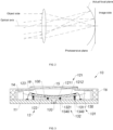
- FIG. 2 illustrates a schematic diagram of an imaging light path of a camera module.
- the actual focal plane (actual focal imaging plane) forms an arc shape that is convex towards the image side, that is, the actual focal plane is an arc-shaped surface.
- the imaging quality is the best.
- the focal plane will still appear as an arc-shaped surface.
- the photosensitive chip In addition to the imaging problem, as the size of the photosensitive chip continues to increase (or the frame rate increases), the photosensitive chip will generate a lot of heat during the working process, and how to achieve heat dissipation is also an urgent problem to be solved.
- the basic idea of the present application is to bend the flat photosensitive chip into a shape adapted to the actual focal imaging plane through a special manufacturing process. In this way, the imaging quality of the camera module is improved. Moreover, a heat dissipation member for enhancing heat dissipation is formed on the back side of the photosensitive chip, so as to solve the problem of heat dissipation.
- the present application proposes a photosensitive assembly, which includes: a circuit board, a photosensitive chip and a shaping member, wherein the circuit board has at least one opening formed therethrough, and the photosensitive chip is electrically connected to the circuit board, and the lower surface of the photosensitive chip is attached to the shaping member to form an accommodating space with the shaping member and the circuit board, and wherein the accommodating space is communicated with the at least one opening, and is configured so that the photosensitive chip is bent downward during the process of assembling the photosensitive assembly.
- the flat photosensitive chip is bent into a shape adapted to the actual focal imaging plane through a special manufacturing process, so as to improve the imaging quality of the camera module.
- the present application further provides a photosensitive assembly, which includes: a photosensitive chip and a shaping member, wherein the circuit board has at least one opening formed therethrough, the photosensitive chip is electrically connected to the circuit board, and the lower surface of the photosensitive chip is attached to the shaping member to form an accommodating space with the shaping member and the circuit board, and wherein the accommodating space is communicated with the at least one opening, and is configured so that the photosensitive chip is bent downward during assembly of the photosensitive assembly.
- the flat photosensitive chip is bent into a shape adapted to the actual focal imaging plane through a special manufacturing process, so as to improve the imaging quality of the camera module.
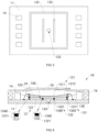
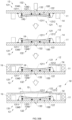
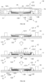
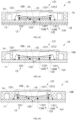
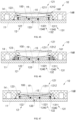
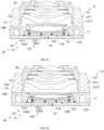
- the photosensitive assembly 10 includes a circuit board 11, a photosensitive chip 12 electrically connected to the circuit board 11, and a shaping member 13, wherein a lower surface 122 of the photosensitive chip 12 is attached to the shaping member 13 to form an accommodating space 100 with the shaping member 13 and the circuit board 11, and the accommodating space 100 is configured so that the photosensitive chip 12 is bent downward during the process of assembling the photosensitive assembly 10.
- the photosensitive chip 12 is bent into a shape adapted to the actual focal plane, and the imaging quality is improved in this way.
- the shaping member 13 is fixed on a top surface of the circuit board 11, wherein a top surface of the shaping member 13 is attached to the lower surface 122 of the photosensitive chip 12 to form the accommodating space 100 with the photosensitive chip 12 and the circuit board 11. It should be understood that the accommodating space 100 below the photosensitive chip 12 provides a deformation space for the photosensitive chip 12 to bend downward under the action of a specific force.
- the shaping member 13 sets a shaping surface 130, wherein the shaping surface 130 is configured to limit the downward bending shape of the photosensitive chip 12, so that the shape of the lower surface 122 of the bent photosensitive chip 12 after bending is adapted to the actual focal plane, and the imaging quality is improved in this way.
- the shaping member 13 includes a first shaping piece 131 and a second shaping piece 132, wherein the first shaping piece 131 is fixed on the circuit board 11, and the lower surface 122 of the photosensitive chip 12 is attached to the first shaping piece 131.
- an accommodating space 100 is formed between the first shaping piece 131, the photosensitive chip 12 and the circuit board 11.
- the second shaping piece 132 is fixed on the circuit board 11 and located in the accommodating space 100, and the height of the second shaping piece 132 is lower than that of the first shaping piece 131.
- the first shaping piece 131 and the second shaping piece 132 are arranged in a stepped shape.
- both an upper surface of the first shaping piece 131 and an upper surface of the second shaping piece 132 include an arc-shaped surface recessed downward and inward, and the arc-shaped surface is configured so that when the photosensitive chip 12 is bent downward, a lower surface 122 adapted to the focal imaging plane of the photosensitive assembly 10 is formed, so as to form a downward curved shaping surface 130 through the upper surfaces of the first shaping piece 131 and the second shaping piece 132.
- the upper surfaces of the first shaping piece 131 and the second shaping piece 132 both include arc-shaped surfaces recessed downward and inward, as shown in FIG. 6 .
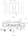
- the shaping member 13 further includes at least one opening 133 formed through the circuit board 11 and communicated with the accommodating space 100, wherein after the photosensitive chip 12 is attached to the first shaping piece 131 to form the accommodating space 100, the at least one opening 133 is configured so that a suction device 40 can be inserted into the accommodating space 100 and attached to at least a part of the lower surface 122 of the photosensitive chip 12, to cause the photosensitive chip 12 to be bent downward by pulling force. That is to say, in the embodiment of the present application, the specific force for bending the photosensitive chip 12 is the pulling force generated by the suction device 40.
- the technical principle of making the photosensitive chip 12 bend downward in the accommodating space 100 is as follows: the suction device 40 for bending the photosensitive chip 12 is inserted into the accommodating space 100 through the opening 133 and sucked to the lower surface 122 of the photosensitive chip 12, so as to force the photosensitive chip 12 to bend downward by pulling the suction device 40 downward.
- FIGS. 4A and 4B illustrate an example of the suction device.
- the suction device 40 includes a suction cup 41 and an extension rod 42 extending downward from the suction cup 41, wherein the suction cup 41 is used for suction on at least part of the lower surface 122 of the photosensitive chip 12, and after the suction cup 41 is attached to the photosensitive chip 12, the photosensitive chip 12 may be bent downward by pulling the extension rod 42.
- the suction device 40 may also be implemented as other types. In this regard, it is not limited in the present application.
- the shape of the circuit board 11 and the photosensitive chip 12 will change.
- the shape of the first shaping piece 131 may also be adjusted adaptively. In this regard, it is not limited in the present application.
- the first shaping pieces 131 are symmetrically arranged on the circuit board 11 with respect to the center of the photosensitive chip 12.
- the first shaping pieces 131 are symmetrically arranged with respect to a center line of longer sides of the photosensitive chip.
- the first shaping piece 131 does not need to form a closed shape, that is, the first shaping piece 131 only needs to ensure that the edges of the shorter sides of the photosensitive chip can be supported.
- the first shaping piece 131 is implemented to be elongated and disposed on the circuit board 12 along the shorter sides of the photosensitive chip 12.
- the size of the first shaping piece 131 is adapted to the size of the photosensitive chip 12, so that when the photosensitive chip 12 is attached to the first shaping piece 131, the first shaping piece 131 is supported on the edge portion of the photosensitive chip 12.
- the upper surface 121 of the photosensitive chip 12 includes a photosensitive area 1211 and a non-photosensitive area 1212 located around the photosensitive area 1211, wherein, since the photosensitive area 1211 is a sensitive area, it is usually disposed at the center portion of the upper surface 121 of the photosensitive chip 12, and the non-photosensitive area 1212 is located at the edge portion of the upper surface 121 and surrounds the photosensitive area 1211.
- the size of the first shaping piece 131 is adapted to the photosensitive chip 12, so that the first shaping piece 131 is supported on the non-photosensitive area 1212 of the photosensitive chip 12. This can ensure that the photosensitive area 1211 of the photosensitive chip 12 will not be damaged during the subsequent bending process of the photosensitive chip 12.
- the premise of the center line of the photosensitive chip 12 mentioned in the present invention is that the photosensitive chip has a regular shape, that is, the photosensitive area 1211 and the non-photosensitive area 1212 of the photosensitive chip 12 are symmetrically distributed with respect to the center.
- the center line of the photosensitive chip 12 in the present invention refers to the center line of the photosensitive area 1211.
- the shape and size of the first shaping piece 131 is adapted to the size and shape of the photosensitive chip 12, so that when the photosensitive chip 12 is attached to the first shaping piece 131, the first shaping piece 131 is supported on the non-photosensitive area 1212 of the photosensitive chip 12, and the center of the first shaping piece 131 is coaxial with the center of the photosensitive chip 12. That is, the photosensitive chip 12 is coaxially attached to the first shaping piece 131.
- the first shaping piece 131 includes a first shaping piece body 1311 and an adhesive 1340 applied on the first shaping piece body, wherein the first shaping piece body 1311 is disposed on the circuit board 11, and the adhesive 1340 is used for bonding the photosensitive chip 12.
- the function of the adhesive 1340 is to bond the first shaping piece body 1311 and the photosensitive chip 12, and the thickness and material thereof do not constitute a limitation of the present application.
- the photosensitive chip 12 may also be directly disposed on the first shaping piece body 1311 by using a process such as ultrasonic welding without the adhesive 1340. That is, in other examples of the present application, the adhesive 1340 is a non-essential element.
- the adhesive 1340 has certain flexibility and relatively high viscosity.
- the second shaping piece 132 should be preset at a preset position of the circuit board 11 in advance, so that after the photosensitive chip 12 is bonded to the first shaping piece 131 to form the accommodating space 100, the second shaping piece 132 is accommodated in the accommodating space 100.
- the height of the second shaping piece 132 is smaller than the height of the first shaping piece 131.
- the height setting of the second shaping piece 132 is related to the relative positional relationship between the second shaping piece 132 and the first shaping piece 131.
- the shape of the shaping surface 130 formed by the first shaping piece 131 and the second shaping piece 132 is set based on the shape of the actual focal plane. That is to say, the relative positional relationship between the first shaping piece 131 and the second shaping piece 132 and the setting of the height difference between the two should match the shape of the actual focal plane.
- the height difference between the first shaping piece 131 and the second shaping piece 132 should be reduced, that is, the height of the shaping member 132 should be increased.
- the height difference between the first shaping piece 131 and the second shaping piece 132 should be increased, that is, the height of the second shaping piece 132 should be reduced.
- the shape of the shaping surface 130 matches the shape of the actual focal plane, which does not mean that the shape of the shaping surface 130 is completely consistent with or completely coincides with the shape of the actual focal plane, and simply means that the shape of the shaping surface 130 tends to be consistent with the shape of the actual focal plane.
- the second shaping pieces 132 are symmetrically arranged with respect to the center of the photosensitive chip 12.
- the bonding points between the second shaping piece 132 and the photosensitive chip 12 are also symmetrically distributed with respect to the center of the photosensitive chip 12, so as to form a uniform bonding force on opposite sides of or around the photosensitive chip 12 to ensure that the photosensitive chip 12 can be more stably shaped.
- the second shaping pieces 132 are symmetrically arranged on both sides of the center line set by the longer sides of the photosensitive chip 12.
- the second shaping piece 132 can also be symmetrically arranged with respect to the center of the photosensitive chip 12 in other ways. It is worth mentioning that, in the embodiment of the present application, the shape of the second shaping piece 132 is not limited in the present application, and includes but is not limited to a slender shape, a column shape, and the like.
- the second shaping piece 132 includes a second shaping piece body 1321 and an adhesive 1340 applied on the second shaping piece body 1321. It should be understood that the photosensitive chip 12 is bonded to the upper surface of the second shaping piece 132 by the adhesive 1340 to prevent the photosensitive chip 12 from being broken due to the suspension in the middle, and to prevent any deformation of the photosensitive chip 12 during use (for example, the photosensitive chip gradually tends to be flat).
- the adhesive 1340 applied to the first shaping piece body 1311 and the adhesive 1340 applied to the second shaping piece body 1321 may be implemented as the same adhesive 1340 or different types of adhesives 1340, and the application amount or thickness of the adhesive 1340 is not limited in the present application.
- the first shaping piece body 1311 and the second shaping piece body 1321 are made of materials with relatively high hardness and relatively high thermal conductivity, for example, metal materials (including pure metal materials, metal and non-metal alloy materials, metal and metal alloy materials).
- metal materials including pure metal materials, metal and non-metal alloy materials, metal and metal alloy materials.
- the first shaping piece body 1311 and the second shaping piece body 1321 each extend between the photosensitive chip 12 and the circuit board 11, so that when the first shaping piece body 1311 and the second shaping piece body 1321 are implemented as being made of metal materials with relatively high thermal conductivity, the heat generated by the operation of the photosensitive chip 12 can be efficiently conducted to the circuit board 11 and finally radiated to the outside by means of the first shaping piece body 1311 and the second shaping piece body 1321.
- the heat dissipation portion it will be further described in the subsequent description, and will not be further described here.
- the photosensitive chip 12 When the photosensitive chip 12 is bonded to the first shaping piece 131 to define the accommodating space 100, there is a certain distance between the lower surface 122 of the photosensitive chip 12 and the adhesive 1340 of the second shaping piece 132.
- the suction device 40 pulls the photosensitive chip 12 to bend downward, the photosensitive chip 12 is continuously bent downward under the action of the pulling force, so that the distance between the lower surface 122 of the photosensitive chip 12 and the second shaping piece 132 is continuously reduced until the lower surface 122 of the photosensitive chip 12 is in contact with the adhesive 1340 of the second shaping piece 132, and the photosensitive chip 12 is also bonded to the second shaping piece 132 by the adhesive 1340.
- the shape of the photosensitive chip 12 is shaped into the shape of the shaping surface 130, so that the shape of the lower surface 122 of the photosensitive chip 12 is adapted to the actual focal plane.
- the position where the opening 133 is formed in the circuit board 11 corresponds to the central area of the photosensitive chip 12.
- the suction cup 41 of the suction device 40 can be attached to the central area of the lower surface 122 of the photosensitive chip 12.
- the bending force generated by the suction device 40 is the largest in the central area of the photosensitive chip 12 and gradually decreases from the central area to the edge portion, so that the deformation of the photosensitive chip 12 gradually increases from the edge of the photosensitive chip 12 to the center of the photosensitive chip 12 to adapt to the shape of the actual focal plane.
- the number of the openings 133 may be set to one or more. In this regard, it is not limited in the present application. It should also be understood that, in other examples of the embodiment of the present application, the openings 133 may also be formed at other positions in the circuit board 11.
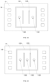
- FIG. 7 illustrates a schematic top view of a modified implementation of the photosensitive assembly according to the embodiment of the present application.
- the position where the opening 133 is formed in the circuit board 11 is located between the first shaping piece 131 and the second shaping piece 132.
- a corresponding number of the suction devices 40 can be used to bend the photosensitive chip.
- the number of the openings 133 is 2, and correspondingly, the number of the suction devices 40 number is also 2.
- the positions where the openings 133 are formed in the circuit board 11 are symmetrically arranged with respect to the central area of the photosensitive chip 12.
- the attachment positions where the suction devices 40 are attached to the photosensitive chip 12 are also symmetrically arranged with respect to the central area of the photosensitive chip 12, so as to form a more uniform pulling force at positions that are symmetrical with respect to the central area of the photosensitive chip 12, so that the photosensitive chip 12 can be bent downward more symmetrically and gently in a manner that tends to the shape of the shaping surface 130.
- FIG. 8 illustrates a schematic top view of another modified implementation of the photosensitive assembly according to the embodiment of the present application.
- the positions where a part of the openings 133 are formed in the circuit board 11 correspond to the central area of the photosensitive chip 12, and the positions where another part of the openings 133 are formed in the circuit board 11 are located between the first shaping piece 131 and the second shaping piece 132.
- a corresponding number of suction devices 40 may be used to bend the photosensitive chip.
- the number of the openings 133 is 3 (wherein 1 opening is disposed in the circuit board 11 at a position corresponding to the central area of the photosensitive chip 12, and the other 2 openings are disposed between the first shaping piece 131 and the second shaping piece 132), and correspondingly, the number of the suction devices 40 is also 3.
- the positions where another part of the openings 133 are formed in the circuit board 11 are symmetrically arranged with respect to the center of the photosensitive chip 12.
- the attachment positions where the suction devices 40 are attached to the lower surface of the photosensitive chip 12 are also symmetrically arranged with respect to the central area of the photosensitive chip 12, so as to form a more uniform force at positions that are symmetrical with respect to the central area of the photosensitive chip 12, so that the photosensitive chip 12 can be bent downward more symmetrically and gently in a manner that tends to the shape of the shaping surface 130.
- the circuit board 11 further includes a first positioning groove 111 and a second positioning groove 112 formed on the top surface of the circuit board 11 in a recessed manner, wherein the first positioning groove 111 is used for positioning to mount the first shaping piece 131 therein in an adapted manner, and the second positioning groove 112 is used for positioning to mount the second shaping piece 132 therein in an adapted manner.
- the first positioning groove 111 is implemented as a first positioning through hole penetrating through the circuit board 11
- the second positioning groove 112 is implemented as a second positioning through hole penetrating through the circuit board 11, wherein the first positioning through hole 111 is used for positioning to mount the first shaping piece 131 therein in an adapted manner, and the second positioning through hole 112 is used for positioning to mount the second shaping piece 132 therein in an adapted manner.
- the photosensitive assembly 10 further includes a reinforcing plate 18 attached to the bottom surface of the circuit board 11.
- the reinforcing plate 18 is made of a metal material with relatively high thermal conductivity. In this way, the heat generated by the photosensitive chip 12 can be directly conducted to the reinforcing plate 18 by means of the first shaping piece 131 and the second shaping piece 132 to achieve the purpose of heat dissipation.
- the first shaping piece 131 and the second shaping piece 132 are prefabricated pieces, that is, the first shaping piece body 1311 and the second shaping piece body 1321 are prefabricated and then attached to preset positions of the circuit board 11.
- the first shaping piece 131 and the second shaping piece 132 may also be integrally molded at the preset positions of the circuit board 11.
- the first shaping piece body 1311 and the second shaping piece body 1321 are made of metal materials
- the first shaping piece body 1311 and the second shaping piece body 1321 may be integrally molded at the preset positions of the circuit board 11 through an electroplating molding process.
- first shaping piece body 1311 and the second shaping piece body 1321 are made of other materials with relatively high hardness and relatively high thermal conductivity
- first shaping piece body 1311 and the second shaping piece body 1321 may be integrally molded at the preset positions of the circuit board 11 using a corresponding integral molding process. In this regard, it is not limited in the present application.
- the shaping member 13 may further include more shaping pieces.
- the shaping member 13 further includes a third shaping piece 134 (including a third shaping piece body 134 and an adhesive 1340 applied to the top surface of the third shaping piece body 134), wherein the third shaping piece 134 is disposed between the first shaping piece 131 and the second shaping piece 132, so as to form the shaping surface 130 by the first shaping piece 131, the second shaping piece 132 and the third shaping piece 134.
- a third shaping piece 134 including a third shaping piece body 134 and an adhesive 1340 applied to the top surface of the third shaping piece body 134
- the third shaping piece 134 is disposed between the first shaping piece 131 and the second shaping piece 132, so as to form the shaping surface 130 by the first shaping piece 131, the second shaping piece 132 and the third shaping piece 134.
- the shaping member 13 only includes the first shaping piece 131, wherein the upper surface of the first shaping piece 131 includes an arc-shaped surface recessed downward and inward, and the arc-shaped surface is configured so that when the photosensitive chip 12 is bent downward, a lower surface 122 that is adapted to the focal imaging plane of the photosensitive assembly 10 is formed.
- FIG. 13 illustrates a schematic view of still another modified implementation of the photosensitive assembly according to the embodiment of the present application.
- the first shaping piece 131 and the second shaping piece 132 both have closed annular shapes, so that an accommodating cavity is formed between the first shaping piece 131 and the second shaping piece 132.
- the shaping member 13 further includes an adhesive 1340 disposed between the first shaping piece 131 and the second shaping piece 132, wherein the height of the highest point on the upper surface of the adhesive 1340 is higher than that of the upper surface of the second shaping piece 132.
- the adhesive 1340 should have relatively high viscosity to prevent the adhesive 1340 from flowing out from the upper surface of the second shaping piece 132. In this way, after the photosensitive chip 12 is attached to the first shaping piece 131, the photosensitive chip 12 is pulled by the suction device 40 to force the photosensitive chip 12 to bend downward until it is bonded to the adhesive 1340 disposed between the first shaping piece 131 and the second shaping piece 132. It is worth mentioning that, in this modified embodiment, the adhesive 1340 may not be disposed on the upper surface of the second shaping piece 132.
- the adhesive 1340 may flow to the upper surface of the second shaping piece 132 during the suction, so that the photosensitive chip 12 is bonded to the second shaping piece 132 by the adhesive 1340 after being bent downward. Thus, the bonding is better and the reliability is improved. Further, the adhesive 1340 may not be higher than the second shaping piece 132. For example, the upper surface of the adhesive 1340 is flush with the upper surface of the second shaping piece 132.
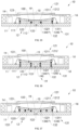
- the photosensitive assembly 10 further includes a heat dissipation member 19 formed in the accommodating space 100, wherein the heat dissipation member 19 is attached to at least a part of the lower surface 122 of the photosensitive chip 12, so that the heat generated by the photosensitive chip 12 can be conducted to the outside by means of the heat dissipation member 19 in contact with the photosensitive chip 12.
- the heat dissipation member 19 needs to be filled in the accommodating space 100, so the first shaping piece 131 is preferably implemented in a closed shape.
- the entire accommodating space 100 is fully filled with the heat dissipation member 19, so that the lower surface 122 of the photosensitive chip 12 is completely in contact with the heat dissipation member 19, so as to maximize the heat dissipation area and improve the heat dissipation performance.
- the formation position and filling ratio of the heat dissipation member 19 in the accommodating space 100 depend on the shape of the second shaping piece 132 and the position setting of the at least one opening 133.
- the heat dissipation member 19 can only occupy at most the cavity surrounded by the second shaping piece 132, the photosensitive chip 12 and the circuit board 11, as shown in FIG. 14 .
- the heat dissipation member 19 can fully occupy the entire accommodating space 100, and only the positions where a part of the openings 133 are formed in the circuit board 11 needs to be set to correspond to the central area of the photosensitive chip 12.
- the positions where another part of the openings 133 are formed in the circuit board 11 are set to be located between the first shaping piece 131 and the second shaping pieces 132.
- a heat dissipation material 190 used to make the heat dissipation member 19 can enter the accommodating space 100 through the opening 133 to form the heat dissipation member 19 in the accommodating space 100.
- the heat dissipation material 190 when the heat dissipation material 190 is implemented as a fluid-like heat dissipation material 190, the fluid-like heat dissipation material 190 may be injected into the accommodating space 100 through the opening 133, to form the heat dissipation member 19 after curing and molding.
- the photosensitive assembly 10 when performing the injection process, the photosensitive assembly 10 may be turned upside down to prevent the fluid-like heat dissipation material 190 from flowing out of the opening 133.
- a ventilation hole 135 may be further provided in the circuit board 11, as shown in FIG. 15 .
- the air intake holes are functionally equivalent to the ventilation hole 135. That is to say, when the number of the openings 133 exceeds one, at least one of the openings forms the ventilation hole 135.
- the entire accommodating space 100 can be fully filled with the heat dissipation material 190. Therefore, on the one hand, after curing and molding, the heat dissipation member 19 is attached to the entire lower surface 122 of the photosensitive chip 12 (a part corresponding to the accommodating space 100) to increase the heat dissipation area. On the other hand, the heat dissipation member 19 extends from the lower surface 122 of the photosensitive chip 12 to the opening 133, that is, the heat dissipation member 19 directly extends to the outside, so as to facilitate heat dissipation.
- the photosensitive assembly 10 further includes a reinforcing plate 18 attached to the bottom surface of the circuit board 11.
- the reinforcing plate 18 is made of a metal material with relatively high thermal conductivity. In this way, the heat dissipation performance of the photosensitive assembly 10 is further enhanced.
- the heat dissipation material 190 may also be implemented in other forms, for example, a granular heat dissipation material 190, as shown in FIG. 16 .
- the granular heat dissipation material 190 may be filled into the accommodating space 100 to form the heat dissipation member 19.
- the photosensitive assembly 10 further includes a reinforcing plate 18 for sealing the opening 133, and preferably, the reinforcing plate 18 is made of a metal material with relatively high thermal conductivity, so as to further enhance the heat dissipation performance of the photosensitive assembly 10 while sealing the opening 133.
- the photosensitive assembly 10 further includes at least one electronic component 14, leads for electrically connecting the photosensitive chip 12 to the circuit board 11, a filter element 15 and a bracket 16, wherein the at least one electronic component 14 is disposed on the circuit board 11 and located around the photosensitive chip 12, and includes but is not limited to a capacitor, a resistor, an inductor and the like.
- each lead 123 extends between the photosensitive chip 12 and the circuit board 11 in a curved manner, so as to electrically connect the photosensitive chip 12 to the circuit board 11 through the leads 123. Therefore, the circuit board 11 can supply power to the photosensitive chip 12 through the leads 123, and the photosensitive chip 12 can transmit the collected signals through the leads 123.
- the type of the lead 123 is not limited in the present application.
- the lead 123 may be a gold wire, a silver wire, or a copper wire.
- the lead 123 can be mounted between the circuit board 11 and the photosensitive chip 12 through a process of "wire bonding", so as to realize the electrical connection between the two.
- the "wire bonding" process is generally divided into two types: “forward wire bonding” process and “reverse wire bonding” process.
- the "forward wire bonding” process means that in the process of laying the lead 123, one end of the lead 123 is first formed on a conductive end of the circuit board 11, the lead 123 is then bent and extended, and finally the other end of the lead 123 is formed on the conductive end of the photosensitive chip 12. In this way, the lead 123 is formed between the photosensitive chip 12 and the circuit board 11.
- the "reverse wire bonding" process means that in the process of laying the lead 123, one end of the lead 123 is first formed on the conductive end of the photosensitive chip 12, the lead 123 is then bent and extended, and finally the other end of the lead 123 is formed on the conductive end of the circuit board 11. In this way, the lead 123 is formed between the photosensitive chip 12 and the circuit board 11. It is worth mentioning that the height of the upward protrusion of the lead 123 formed through the "reverse wire bonding" process is lower relative to the height of the upward protrusion of the lead 123 formed through the "forward wire bonding" process. Therefore, preferably, In this specific implementation, the lead 123 is formed using the "reversed wire bonding" process.
- the photosensitive chip 12 and the circuit board 11 may be connected in other ways (the lead 123 may not be used).
- the lead 123 may not be used.
- a back-connected technical solution is used. In this regard, it is not limited in the present application.
- the bracket 16 is disposed on the circuit board 11 for supporting the filter element 15.
- the bracket 16 is implemented as a conventional plastic bracket 16, which is prefabricated and attached to the top surface of the circuit board 11, wherein the filter element 15 is mounted on the top of the bracket 16 corresponding to at least the photosensitive area 1211 of the photosensitive chip 12, and is used for filtering the light entering the photosensitive chip 12 to improve the imaging quality.
- the photosensitive assembly 10 is based on a conventional COB process.
- the filter element 15 can be implemented in different types, including but not limited to the following: the filter element 15 can be implemented as an infrared cut-off filter, a full transmission spectrum filter and other filters or a combination of multiple filters. Specifically, for example, when the filter element 15 is implemented as a combination of an infrared cut-off filter and a full transmission spectrum filter, that is, the infrared cut-off filter and the full transmission spectrum filter can be switched to be selectively located on the photosensitive path of the photosensitive chip 12.
- the infrared cut-off filter when used in an environment with sufficient light such as daytime, can be switched to the photosensitive path of the photosensitive chip 12 to filter infrared rays in the light reflected by an object entering the photosensitive chip 12 through the infrared cut-off filter, and when used in an environment with less light such as night, the full transmission spectrum filter can be switched to the photosensitive path of the photosensitive chip 12 to allow the infrared part in the light reflected by the object entering the photosensitive chip 12 to transmit therethrough.
- FIG. 17 illustrates a schematic view of still another modified implementation of the photosensitive assembly according to the embodiment of the present application.
- the photosensitive assembly 10 is fabricated based on a Molding on Board (MOB) process.
- the bracket 16 is implemented as a molded bracket 16A, which is integrally molded on the circuit board 11 through a molding process, so as to integrally cover at least a part of the circuit board 11 and at least part of the electronic components 14.
- the circuit board 11 may be placed in a lower mold, and then an upper mold matched with the lower mold is provided to form a molding cavity between the upper and lower molds after the two molds are clamped, wherein the upper mold includes a pressing block that is pressed against the circuit board 11 when the molds are clamped. Further, the molding material is injected into the molding cavity, and after curing, molding, and drafting, the molded bracket 16A integrally covering at least a part of the circuit board 11 and at least a part of the electronic components 14 is obtained.
- the shape of the inner side surface of the molded bracket 16A is determined by the shape of the pressing block. For example, when the side surface of the pressing block is perpendicular to the circuit board 11, the inner side surface of the molded bracket 16A is perpendicular to the upper surface 121 of the photosensitive chip 12. For another example, when the inner side surface of the pressing block is inclined to the circuit board 11, the inner side surface of the molded bracket 16A extends obliquely outward.
- the photosensitive assembly 10 is made based on the MOB process, preferably after the molded bracket 16 is integrally formed at the preset position of the circuit board 11, the first shaping piece 131 and the second shaping piece 132 of the shaping assembly are then mounted at the preset positions of the circuit board 11.
- Such a manufacturing sequence is advantageous to engineering implementation.
- FIG. 18 illustrates a schematic view of still another modified implementation of the photosensitive assembly according to the embodiment of the present application.
- the photosensitive assembly 10 is fabricated based on the Molding on Chip (MOC) process.
- the bracket 16 is implemented as a molded bracket 16B, which is integrally molded on the circuit board 11 through a molding process to integrally cover at least a part of the circuit board 11, the at least one electronic component 14 and at least a part of the non-photosensitive area 1212 of the photosensitive chip 12.
- the semi-finished assembly is placed in a lower mold, and an upper mold matched with the lower mold is provided to form a molding cavity between the upper and lower molds after the two molds are clamped.
- the upper mold includes a pressing block, wherein the pressing block is pressed against the non-photosensitive area 1212 of the photosensitive chip 12 when the molds are clamped.
- the molding material is injected into the molding cavity, and after curing, molding and drafting, the molded bracket 16B integrally covering at least a part of the circuit board 11, the at least one electronic component 14, and at least a part of the non-photosensitive area 1212 of the photosensitive chip 12 is obtained, wherein the area occupied by the pressing block correspondingly forms the light-passing hole for the photosensitive chip 12.
- the shape of the inner side surface of the molded bracket 16B is determined by the shape of the pressing block.
- the inner side surface of the molded bracket 16B is perpendicular to the upper surface 121 of the photosensitive chip 12.
- the inner side surface of the molded bracket 16B extends obliquely outward.
- the inner side surface of the pressing block has a stepped shape
- the inner side surface of the molded bracket 16 also has a stepped shape, so as to form a mounting platform 160 for mounting the filter element 15 on the top surface of the molded bracket 16B.
- this technical solution is defined as an IOM (IR Filter on Molding) solution in the present application, as shown in FIG. 19 .
- the first shaping piece 131 and the second shaping piece 132 of the shaping assembly are mounted or integrally molded at the preset positions of the circuit board 11 in advance before the molded bracket 16 is integrally molded at preset positions of the circuit board 11 and the photosensitive chip 12.
- Such a manufacturing sequence is advantageous to engineering implementation.
- FIG. 21 illustrates a schematic view of still another modified implementation of the photosensitive assembly according to the embodiment of the present application.
- the filter element 15 is stacked above the photosensitive chip 12, and the bracket 16 is implemented as a molded bracket 16C, which is integrally molded through a molding process to cover at least a part of the circuit board 11, the at least one electronic component 14, at least a part of the non-photosensitive area 1212 of the photosensitive chip 12 and at least a part of the filter element 15.
- the filter element 15 is stacked above the photosensitive chip 12 to form a semi-finished assembly. Further, the semi-finished assembly is placed in a lower mold, and an upper mold matched with the lower mold is provided to form a molding cavity between the upper and lower molds after the two molds are clamped.
- the upper mold includes a pressing block, wherein the pressing block is pressed against the filter element 15 when the molds are clamped.
- the molding material is injected into the molding cavity, and after curing, molding and drafting, the molded bracket 16C integrally covering at least a part of the circuit board 11, the at least one electronic component 14, and at least a part of the non-photosensitive area 1212 of the photosensitive chip 12 is obtained, wherein the area occupied by the pressing block correspondingly forms the light-passing hole for the photosensitive chip 12.
- the shape of the inner side surface of the molded bracket 16C is determined by the shape of the pressing block.
- the inner side surface of the molded bracket 16C is perpendicular to the filter element 15.
- the inner side surface of the molded bracket 16C extends obliquely outward.
- this technical solution is defined as an IOC (IR Filter on Chip) solution in the present application.
- the filter element 15 in addition to the filter element 15 being supported on the bracket 16 (including the plastic bracket 16, and the molded brackets 16A, 16B, 16C) and the photosensitive chip 12, the filter element 15 may also be mounted in other ways, as long as the filter element 15 is held in the photosensitive path of the photosensitive assembly 10.
- the photosensitive assembly 10 further includes a filter element holder 17, and the filter element holder 17 is mounted on the bracket 16, and is used for mounting the filter element 15.
- the filter element 15 may also be supported in the optical lens 20, or may be formed on the surface of the lens element in the optical lens 20 in the form of coating. In this regard, it is not limited in the present application.
- the photosensitive assembly based on the embodiment of the present application is explained, wherein the flat photosensitive chip is bent into a shape adapted to the actual focal imaging plane through a special manufacturing process, so as to improve the imaging quality of the camera module.
- the manufacturing process for the photosensitive assembly 10 will be described below from the perspective of the manufacturing steps.
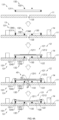
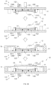
- FIGS. 4A and 4B the manufacturing process for the photosensitive assembly 10 based on the embodiment of the present application is explained, which is used for fabricating the photosensitive assembly as described above and its modified implementation.
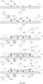
- the method for manufacturing the photosensitive assembly 10 includes the following steps: First, a circuit board 11, a photosensitive chip 12, a first shaping piece 131 and a second shaping piece 132 are provided, wherein the circuit board 11 includes at least one opening 133. It is worth mentioning that the openings 133 in the circuit board 11 may also be formed through a perforation process after the accommodating space 100 is formed. In this regard, it is not limited in the present application.
- the first shaping piece 131 and the second shaping piece 132 are fixed at preset positions of the circuit board 11.
- the photosensitive chip 12 is attached to the first shaping piece 131 to define an accommodating space 100 between the first shaping piece 131, the circuit board 11 and the photosensitive chip 12, wherein the opening 133 formed in the circuit board 11 is communicated with the accommodating space 100, wherein the second shaping piece 132 is located in the accommodating space 100, and the height of the second shaping piece 132 is lower than that of the first shaping piece 131, and wherein the upper surface of at least one of the first shaping piece and the second shaping piece includes an arc-shaped surface recessed downward and inward.
- the suction device 40 is attached to at least a part of the lower surface 122 of the photosensitive chip 12 through the opening 133.
- the photosensitive chip 12 is pulled down by the suction device 40, so that the photosensitive chip 12 is bent downward.
- the suction device 40 includes a suction cup 41 and an extension rod 42 extending downward from the suction cup 41, wherein the suction cup 41 is used for suction on at least part of the lower surface 122 of the photosensitive chip 12, and after the suction cup 41 is attached to the photosensitive chip 12, the photosensitive chip 12 may be bent downward by pulling the extension rod 42.
- the suction device 40 may also be implemented as other types. In this regard, it is not limited in the present application.
- the position where the opening 133 is formed in the circuit board 11 corresponds to the central area of the photosensitive chip 12.
- the suction cup 41 of the suction device 40 can be attached to the central area of the lower surface 122 of the photosensitive chip 12.
- the bending force generated by the suction device 40 is the largest in the central area of the photosensitive chip 12 and gradually decreases from the central area to the edge portion, so that the deformation of the photosensitive chip 12 gradually increases from the edge of the photosensitive chip 12 to the center of the photosensitive chip 12 to adapt to the shape of the actual focal plane.
- the number of the openings 133 may be set to one or more. In this regard, it is not limited in the present application. It should also be understood that, in other examples of the embodiment of the present application, the openings 133 may also be formed at other positions in the circuit board 11.
- the first shaping piece 131 should have a closed shape (for example, it is implemented to have a -like shape), and the second shaping pieces 132 are symmetrically arranged with respect to the center of the photosensitive chip 12.
- the height setting of the second shaping piece 132 is related to the relative positional relationship between the second shaping piece 132 and the first shaping piece 131.
- the shape of the shaping surface 130 defined by the first shaping piece 131 and the second shaping piece 132 for defining the curved shape of the photosensitive chip 12 is set based on the shape of the actual focal plane.
- the height difference between the first shaping piece 131 and the second shaping piece 132 should be reduced (that is, the height of the second shaping piece 132 should be increased); and when the second shaping piece 132 is away from the first shaping piece 131, the height difference between the first shaping piece 131 and the second shaping piece 132 should be increased (that is, the height of the second shaping piece 132 should be reduced).
- both an upper surface of the first shaping piece 131 and an upper surface of the second shaping piece 132 include an arc-shaped surface recessed downward and inward, and the arc-shaped surface is configured so that when the photosensitive chip 12 is bent downward, a lower surface 122 adapted to the focal imaging plane of the photosensitive assembly 10 is formed, so as to form a downward curved shaping surface 130 through the upper surfaces of the first shaping piece 131 and the second shaping piece 132.
- the upper surfaces of the first shaping piece 131 and the second shaping piece 132 both include arc-shaped surfaces recessed downward and inward.
- the process of bending the photosensitive chip 12 includes: bending the photosensitive chip 12 until the lower surface 122 of the photosensitive chip 12 is attached to the arc-shaped surface, so that when the photosensitive chip 12 is bent downward, a lower surface adapted to a focal imaging plane of the photosensitive assembly 10 is formed.
- the manufacturing method further includes the following step: forming a heat dissipation member 19 in the accommodating space 100 defined by the first shaping piece 131, the photosensitive chip 12 and the circuit board 11, wherein the heat dissipation member 19 is attached to at least a part of the lower surface 122 of the photosensitive chip 12.
- the entire accommodating space 100 is fully filled with the heat dissipation member 19, so that the lower surface 122 (a part corresponding to the accommodating space 100) of the photosensitive chip 12 is completely in contact with the heat dissipation member 19, so as to maximize the heat dissipation area and improve the heat dissipation performance.
- the process of forming the heat dissipation member 19 in the accommodating space 100 includes: injecting the fluid-like heat dissipation material 190 into the accommodating space 100 through the opening 133 to form the heat dissipation member 19 after curing and molding.
- the photosensitive assembly 10 may be turned upside down to prevent the fluid-like heat dissipation material 190 from flowing out of the opening 133.
- a ventilation hole 135 may be further provided in the circuit board 11.
- the air intake holes except those being used for injecting the heat dissipation material 190, are functionally equivalent to the ventilation hole 135. That is to say, when the number of the openings 133 exceeds one, at least one of the openings forms the ventilation hole 135.
- a reinforcing plate 18 may be further attached to the bottom surface of the circuit board 11, wherein preferably, the reinforcing plate 18 is made of a metal material with relatively high thermal conductivity. In this way, the heat dissipation performance of the photosensitive assembly 10 is further enhanced.
- the heat dissipation material 190 is implemented in a granular heat dissipation material 190.
- the process of forming the heat dissipation member 19 in the accommodating space 100 includes: injecting the fluid-like heat dissipation material 190 into the accommodating space 100 through the opening 133; and attaching a reinforcing plate 18 to the bottom surface of the circuit board 11 to seal the opening 133 through the reinforcing plate 18.
- the reinforcing plate 18 is made of a metal material with relatively high thermal conductivity, so as to further enhance the heat dissipation performance of the photosensitive assembly 10 while sealing the opening 133.
- the manufacturing process for the photosensitive assembly 10 further includes: disposing the bracket 16 on the circuit board 11, and mounting a filter element 15 on the bracket 16.
- the bracket 16 is implemented as a conventional plastic bracket 16.
- the process of disposing the bracket 16 on the circuit board 11 is embodied in the following step: attaching and mounting the plastic bracket 16 to the circuit board 11. Further, the filter element 15 is attached and mounted to the bracket 16.
- the bracket 16 is implemented as a molded bracket 16A.
- the process of disposing the bracket 16 on the circuit board 11 includes: integrally molding the molded bracket 16A on the circuit board 11 through a molding process, wherein the molded bracket 16A covers at least a part of the circuit board 11 and at least a part of the at least one electronic component 14. Further, the filter element 15 is attached and mounted to the molded bracket 16A.
- the first shaping piece 131 and the second shaping piece 132 are mounted at preset positions of the circuit board 11 after the molded bracket 16 is integrally molded at a preset position of the circuit board 11.
- Such a manufacturing sequence is advantageous to engineering implementation.
- the bracket 16 is implemented as a molded bracket 16B.
- the process of disposing the bracket 16 on the circuit board 11 includes: integrally forming the molded bracket 16B on the circuit board 11 through a molding process, wherein the molded bracket 16B covers at least a part of the circuit board 11, the at least one electronic component 14, and at least a part of the non-photosensitive area 1212 of the photosensitive chip 12. Further, the filter element 15 is attached and mounted to the molded bracket 16B.
- the process further includes applying a side encapsulation 161 on the side parts of the photosensitive chip 12 and the first shaping piece 131, so that the side encapsulation 161 encloses the side parts of the photosensitive chip 12 and the first shaping piece 131. In this way, the position of the photosensitive chip 12 is prevented from being shifted during the molding process.
- the bracket 16 is implemented as a molded bracket 16C.
- the process of disposing the bracket 16 on the circuit board 11 includes: stacking the filter element 15 on the photosensitive chip 12, and integrally molding the molded bracket 16C on the circuit board 11, wherein the molded bracket 16C integrally covers at least a part of the circuit board 11, the at least one electronic component 14, at least a part of a non-photosensitive area 1212 of the photosensitive chip 12, and at least a part of the filter element 15.
- the shape of the inner side surface of the molded bracket 16 is determined by the shape of the pressing block.
- the inner side surface of the molded bracket 16 also has a stepped shape, so as to form a mounting platform 160 for mounting the filter element 15 on a top surface of the molded bracket 16.
- the filter element 15 is mounted on the mounting platform 160.
- the filter element 15 in addition to the filter element 15 being supported on the bracket 16 (including the plastic bracket 16, and the molded brackets 16A, 16B, 16C) and the photosensitive chip 12, the filter element 15 may also be mounted in other ways, as long as the filter element 15 is held in the photosensitive path of the photosensitive assembly 10.
- the photosensitive assembly 10 further includes a filter element holder 17, and the filter element holder 17 is mounted on the bracket 16, and is used for mounting the filter element 15.
- the filter element 15 may also be supported in the optical lens 20, or may be formed on the surface of the lens element in the optical lens 20 in the form of coating. In this regard, it is not limited in the present application.
- the manufacturing process for the photosensitive assembly 10 includes the following steps: First of all, a circuit board 11 and a photosensitive chip 12 are provided, wherein the circuit board 11 comprises at least one opening 133. It is worth mentioning that the openings 133 in the circuit board 11 may also be formed through a perforation process after the accommodating space 100 is formed. In this regard, it is not limited in the present application.
- a first shaping piece 131 and a second shaping piece 132 are integrally molded on the circuit board 11, wherein the height of the second shaping piece 132 is lower than that of the first shaping piece 131. In this way, the first shaping piece and the second shaping piece 132 define a recessed shaping surface 130.
- the photosensitive chip 12 is attached to the first shaping piece 131 to define an accommodating space 100 between the first shaping piece 131, the circuit board 11 and the photosensitive chip 12 in this way, wherein the opening 133 is communicated with the accommodating space 100.
- the suction device 40 is attached to at least a part of the lower surface 122 of the photosensitive chip 12 through the opening 133.
- the photosensitive chip 12 is pulled down by the suction device 40, so that the photosensitive chip 12 is bent downward.
- the first shaping piece 131 and the second shaping piece 132 are integrally molded on the circuit board 11 instead of being prefabricated and then mounted.
- the process of integrally molding a first shaping piece 131 and a second shaping piece 132 on the circuit board 11 includes:
- the suction device 40 includes a suction cup 41 and an extension rod 42 extending downward from the suction cup 41, wherein the suction cup 41 is used for suction on at least part of the lower surface 122 of the photosensitive chip 12, and after the suction cup 41 is attached to the photosensitive chip 12, the photosensitive chip 12 may be bent downward by pulling the extension rod 42.
- the suction device 40 may also be implemented as other types. In this regard, it is not limited in the present application.
- the position where the opening 133 is formed in the circuit board 11 corresponds to the central area of the photosensitive chip 12.
- the suction cup 41 of the suction device 40 can be attached to the central area of the lower surface 122 of the photosensitive chip 12.
- the bending force generated by the suction device 40 is the largest in the central area of the photosensitive chip 12 and gradually decreases from the central area to the edge portion, so that the deformation of the photosensitive chip 12 gradually increases from the edge of the photosensitive chip 12 to the center of the photosensitive chip 12 to adapt to the shape of the actual focal plane.
- the number of the openings 133 may be set to one or more. In this regard, it is not limited in the present application. It should also be understood that, in other examples of the embodiment of the present application, the openings 133 may also be formed at other positions in the circuit board 11.
- the first shaping piece 131 should have a closed shape (for example, it is implemented to have a -like shape), and the second shaping pieces 132 are symmetrically arranged with respect to the center of the photosensitive chip 12.
- the height setting of the second shaping piece 132 is related to the relative positional relationship between the second shaping piece 132 and the first shaping piece 131.
- the shape of the shaping surface 130 defined by the first shaping piece 131 and the second shaping piece 132 for defining the curved shape of the photosensitive chip 12 is set based on the shape of the actual focal plane.
- the height difference between the first shaping piece 131 and the second shaping piece 132 should be reduced (that is, the height of the second shaping piece 132 should be increased); and when the second shaping piece 132 is away from the first shaping piece 131, the height difference between the first shaping piece 131 and the second shaping piece 132 should be increased (that is, the height of the second shaping piece 132 should be reduced).
- both an upper surface of the first shaping piece 131 and an upper surface of the second shaping piece 132 include an arc-shaped surface recessed downward and inward, and the arc-shaped surface is configured so that when the photosensitive chip 12 is bent downward, a lower surface 122 adapted to the focal imaging plane of the photosensitive assembly 10 is formed, so as to form a downward curved shaping surface 130 through the upper surfaces of the first shaping piece 131 and the second shaping piece 132.
- the upper surfaces of the first shaping piece 131 and the second shaping piece 132 both include arc-shaped surfaces recessed downward and inward.
- the process of bending the photosensitive chip 12 includes: bending the photosensitive chip 12 until the lower surface 122 of the photosensitive chip 12 is attached to the arc-shaped surface, so that when the photosensitive chip 12 is bent downward, a lower surface adapted to a focal imaging plane of the photosensitive assembly 10 is formed.
- the fabrication process for the photosensitive assembly 10 further includes the following step: injecting a heat dissipation material into the accommodating space 100 through the opening 133 to form the heat dissipation member in the accommodating space 100, wherein the heat dissipation member is attached to at least a part of the lower surface 122 of the photosensitive chip 12.
- the entire accommodating space 100 is fully filled with the heat dissipation member 19, so that the lower surface 122 (a part corresponding to the accommodating space 100) of the photosensitive chip 12 is completely in contact with the heat dissipation member 19, so as to maximize the heat dissipation area and improve the heat dissipation performance.
- the process of forming the heat dissipation member 19 in the accommodating space 100 includes: injecting the fluid-like heat dissipation material 190 into the accommodating space 100 through the opening 133 to form the heat dissipation member 19 after curing and molding.
- the photosensitive assembly 10 may be turned upside down to prevent the fluid-like heat dissipation material 190 from flowing out of the opening 133.
- a ventilation hole 135 may be further provided in the circuit board 11.
- the openings 133 except those being used for injecting the heat dissipation material 190, are functionally equivalent to the ventilation hole 135. That is to say, when the number of the openings 133 exceeds one, at least one of the openings 133 forms the ventilation hole 135.
- a reinforcing plate 18 may be further attached to the bottom surface of the circuit board 11, wherein preferably, the reinforcing plate 18 is made of a metal material with relatively high thermal conductivity. In this way, the heat dissipation performance of the photosensitive assembly 10 is further enhanced.
- the manufacturing process for the photosensitive assembly 10 further includes: disposing the bracket 16 on the circuit board 11, and mounting a filter element 15 on the bracket 16.
- the bracket 16 is implemented as a conventional plastic bracket 16.
- the process of disposing the bracket 16 on the circuit board 11 is embodied in the following step: attaching and mounting the plastic bracket 16 to the circuit board 11. Further, the filter element 15 is attached and mounted to the bracket 16.
- the bracket 16 is implemented as a molded bracket 16A.
- the process of disposing the bracket 16 on the circuit board 11 includes: integrally molding the molded bracket on the circuit board 11 through a molding process, wherein the molded bracket 16A covers at least a part of the circuit board 11 and at least a part of the at least one electronic component 14. Further, the filter element 15 is attached and mounted to the molded bracket.
- the bracket 16 is implemented as a molded bracket.
- the process of disposing the bracket 16 on the circuit board 11 includes: integrally forming the molded bracket on the circuit board 11 through a molding process, wherein the molded bracket covers at least a part of the circuit board 11, the at least one electronic component 14, and at least a part of the non-photosensitive area 1212 of the photosensitive chip 12. Further, the filter element 15 is attached and mounted to the molded bracket.
- the process further includes applying a side encapsulation 161 on the side parts of the photosensitive chip 12 and the shaping member 13, so that the side encapsulation 161 encloses the side parts of the photosensitive chip 12 and the shaping member 13. In this way, the position of the photosensitive chip 12 is prevented from being shifted during the molding process.
- the bracket 16 is implemented as a molded bracket.
- the process of disposing the bracket 16 on the circuit board 11 includes: stacking the filter element 15 on the photosensitive chip 12, and integrally molding the molded bracket 16C on the circuit board 11, wherein the molded bracket 16C integrally covers at least a part of the circuit board 11, the at least one electronic component 14, at least a part of a non-photosensitive area 1212 of the photosensitive chip 12, and at least a part of the filter element 15.
- the shape of the inner side surface of the molded bracket 16 is determined by the shape of the pressing block.
- the inner side surface of the molded bracket 16 also has a stepped shape, so as to form a mounting platform 160 for mounting the filter element 15 on a top surface of the molded bracket 16.
- the filter element 15 is mounted on the mounting platform 160.
- the filter element 15 in addition to the filter element 15 being supported on the bracket 16 (including the plastic bracket and the molded brackets) and the photosensitive chip 12, the filter element 15 may also be mounted in other ways, as long as the filter element 15 is held in the photosensitive path of the photosensitive assembly 10.
- the photosensitive assembly 10 further includes a filter element holder 17, and the filter element holder 17 is mounted on the bracket 16, and is used for mounting the filter element 15.
- the filter element 15 when the photosensitive assembly 10 cooperates with the optical lens 20 to form a camera module, the filter element 15 may also be supported in the optical lens 20, or may be formed on the surface of the lens element in the optical lens 20 in the form of coating. In this regard, it is not limited in the present application.
- the manufacturing method for the photosensitive assembly 10 based on the embodiment of the present application is explained, wherein the flat photosensitive chip 12 is bent into a shape adapted to the actual focal imaging plane through the special manufacturing process, so as to improve the imaging quality of the camera module. Moreover, the heat dissipation member 19 for enhancing heat dissipation is formed on the back side of the photosensitive chip 12, so as to improve the heat dissipation performance.
- the photosensitive assembly 10 as described above to a camera module will be specifically described below. It is known by those skilled in the art that the camera module includes an auto-focus camera module and a fixed-focus camera module.
- the camera module When the camera module is implemented as a fixed-focus camera module, the camera module includes photosensitive assembly as described above and an optical lens 20, wherein the optical lens 20 is held in a photosensitive path of the photosensitive assembly 10.
- the optical lens 20 is usually mounted on the bracket 16 to hold the optical lens 20 on the photosensitive path of the photosensitive assembly 10, and for its specific effect, reference may be made to FIGS. 23 to 27 .
- FIGS. 23 to 27 It is worth mentioning that the drawings only illustrate several typical photosensitive assemblies in the embodiments of the present application, and the corresponding modified implementations thereof are not listed one by one. In this regard, it should be fully understood by those skilled in the art.
- the external light first passes through the optical lens 20, and is then collected by the photosensitive chip 12 after being filtered by the filter element 15.
- the photosensitive chip 12 is bent based on the shape of the actual focal plane, and in this way, the imaging quality of the camera module is improved.
- the camera module When the camera module is implemented as an auto-focus camera module, as shown in FIG. 28 , the camera module includes photosensitive assembly as described above, an optical lens 20 and a driving element 30, wherein the driving element 30 is mounted on the bracket 16, and the optical lens 20 is mounted on the driving element 30.
- the driving element 30 can carry the optical lens 20 to move along the photosensitive path of the photosensitive assembly 10, so as to realize the auto-focus function.
- the drawings only illustrate a typical photosensitive assembly in the embodiment of the present application, and the corresponding modified implementations are not listed one by one. In this regard, it should be fully understood by those skilled in the art.
- the photosensitive assembly 10 includes a circuit board 11, a photosensitive chip 12 electrically connected to the circuit board 11, and a shaping member 13, wherein a lower surface 122 of the photosensitive chip 12 is attached to the shaping member 13 to form an accommodating space 100 with the shaping member 13 and the circuit board 11, and the accommodating space 100 is configured so that the photosensitive chip 12 is bent downward during the process of assembling the photosensitive assembly 10.
- the photosensitive chip 12 is bent into a shape adapted to the actual focal plane, and the imaging quality is improved in this way.
- the shaping member 13 is fixed on a top surface of the circuit board 11, wherein a top surface of the shaping member 13 is attached to the lower surface 122 of the photosensitive chip 12 to form the accommodating space 100 with the photosensitive chip 12 and the circuit board 11. It should be understood that the accommodating space 100 below the photosensitive chip 12 provides a deformation space for the photosensitive chip 12 to bend downward under the action of a specific force.
- the shaping member 13 sets a shaping surface 130, wherein the shaping surface 130 is configured to limit the downward bending shape of the photosensitive chip 12, so that the shape of the lower surface 122 of the bent photosensitive chip 12 is adapted to the actual focal plane, and the imaging quality is improved in this way.
- the shaping member 13 includes a first shaping piece 131 and a second shaping piece 132, wherein the first shaping piece 131 is fixed on the circuit board 11, and the lower surface 122 of the photosensitive chip 12 is attached to the first shaping piece 131.
- an accommodating space 100 is formed between the first shaping piece 131, the photosensitive chip 12 and the circuit board 11.
- the second shaping piece 132 is fixed on the circuit board 11 and located in the accommodating space 100, and the height of the second shaping piece 132 is lower than that of the first shaping piece 131.
- the first shaping piece 131 and the second shaping piece 132 are arranged in a stepped shape.
- both an upper surface of the first shaping piece 131 and an upper surface of the second shaping piece 132 include an arc-shaped surface recessed downward and inward, and the arc-shaped surface is configured so that when the photosensitive chip 12 is bent downward, a lower surface 122 adapted to the focal imaging plane of the photosensitive assembly 10 is formed, so as to form a downward curved shaping surface 130 through the upper surfaces of the first shaping piece 131 and the second shaping piece 132.
- the upper surfaces of the first shaping piece 131 and the second shaping piece 132 both include arc-shaped surfaces recessed downward and inward, as shown in FIG. 32 .
- the shaping member 13 further includes at least one opening 133 formed through the circuit board 11 and communicated with the accommodating space 100, wherein after the photosensitive chip 12 is attached to the first shaping piece 131 to form the accommodating space 100, and the gas in the accommodating space 100 can be discharged through the opening 133 to form a pressure difference between the upper and lower surfaces 121, 122 of the photosensitive chip 12, so as to force the photosensitive chip 12 to bend downward until it is attached to the shaping surface 130 formed by the first shaping piece 131 and the second shaping piece 132.
- the first shaping piece 131 has a closed shape.
- the shape of the first shaping piece 131 is adapted to the shape of the circuit board 11 and the photosensitive chip 12. It should be known by those skilled in the art that the shape of the existing circuit board 11 and photosensitive chip 12 is usually a rectangle.
- the shape of the first shaping piece 131 is preferably implemented as a closed -like shape.
- the shape of the first shaping piece 131 may also be adjusted adaptively. In this regard, it is not limited in the present application.
- the -shaped first shaping piece 131 has an opening.
- the opening is shielded by the photosensitive chip 12 attached to the first shaping piece 131, so that the photosensitive chip 12, the circuit board 11 and the first shaping piece 131 enclose to form the accommodating space 100.
- the size of the first shaping piece 131 is adapted to the size of the photosensitive chip 12, so that when the photosensitive chip 12 is attached to the first shaping piece 131, the first shaping piece 131 is supported on the edge portion of the photosensitive chip 12.
- the upper surface 121 of the photosensitive chip 12 includes a photosensitive area 1211 and a non-photosensitive area 1212 located around the photosensitive area 1211, wherein, since the photosensitive area 1211 is a sensitive area, it is usually disposed at the center portion of the upper surface 121 of the photosensitive chip 12, and the non-photosensitive area 1212 is located at the edge portion of the upper surface 121 and surrounds the photosensitive area 1211. That is to say, the size of the first shaping piece 131 is adapted to the photosensitive chip 12, so that the first shaping piece 131 is supported on the non-photosensitive area 1212 of the photosensitive chip 12.
- the premise of the center line of the photosensitive chip 12 mentioned in the present invention is that the photosensitive chip has a regular shape, that is, the photosensitive area 1211 and the non-photosensitive area 1212 of the photosensitive chip 12 are symmetrically distributed with respect to the center.
- the center line of the photosensitive chip 12 in the present invention refers to the center line of the photosensitive area 1211.
- the shape and size of the first shaping piece 131 is adapted to the size and shape of the photosensitive chip 12, so that when the photosensitive chip 12 is attached to the first shaping piece 131, the first shaping piece 131 is supported on the non-photosensitive area 1212 of the photosensitive chip 12, and the center of the first shaping piece 131 is coaxial with the center of the photosensitive chip 12. That is, the photosensitive chip 12 is coaxially attached to the first shaping piece 131.
- the first shaping piece 131 includes a first shaping piece body 1311 and an adhesive 1340 applied on the first shaping piece body, wherein the first shaping piece body 1311 is disposed on the circuit board 11, and the adhesive 1340 is used for bonding the photosensitive chip 12.
- the function of the adhesive 1340 is to bond the first shaping piece body 1311 and the photosensitive chip 12, and the thickness and material thereof do not constitute a limitation of the present application.
- the photosensitive chip 12 may also be directly disposed on the first shaping piece body 1311 by using a process such as ultrasonic welding without the adhesive 1340. That is, in other examples of the present application, the adhesive 1340 is a non-essential element.
- the adhesive 1340 has certain flexibility and relatively high viscosity.
- the second shaping piece 132 should be preset at a preset position of the circuit board 11 in advance, so that after the photosensitive chip 12 is bonded to the first shaping piece 131 to form the accommodating space 100, the second shaping piece 132 is accommodated in the accommodating space 100.
- the height of the second shaping piece 132 is smaller than the height of the first shaping piece 131.
- the height setting of the second shaping piece 132 is related to the relative positional relationship between the second shaping piece 132 and the first shaping piece 131.
- the shape of the shaping surface 130 formed by the first shaping piece 131 and the second shaping piece 132 is set based on the shape of the actual focal plane. That is to say, the relative positional relationship between the first shaping piece 131 and the second shaping piece 132 and the setting of the height difference between the two should match the shape of the actual focal plane.
- the height difference between the first shaping piece 131 and the second shaping piece 132 should be reduced, that is, the height of the shaping member 132 should be increased.
- the height difference between the first shaping piece 131 and the second shaping piece 132 should be increased, that is, the height of the second shaping piece 132 should be reduced.
- the shape of the shaping surface 130 matches the shape of the actual focal plane, which does not mean that the shape of the shaping surface 130 is completely consistent with or completely coincides with the shape of the actual focal plane, and simply means that the shape of the shaping surface 130 tends to be consistent with the shape of the actual focal plane.
- the second shaping pieces 132 are symmetrically arranged with respect to the center of the photosensitive chip 12.
- the bonding points between the second shaping piece 132 and the photosensitive chip 12 are also symmetrically distributed with respect to the center of the photosensitive chip 12, so as to form a uniform bonding force on opposite sides of or around the photosensitive chip 12 to ensure that the photosensitive chip 12 can be more stably shaped.
- the second shaping pieces 132 are symmetrically arranged on both sides of the center line set by the longer sides of the photosensitive chip 12.
- the second shaping piece 132 can also be symmetrically arranged with respect to the center of the photosensitive chip 12 in other ways. It is worth mentioning that, in the embodiment of the present application, the shape of the second shaping piece 132 is not limited in the present application, and includes but is not limited to a slender shape, a column shape, and the like.
- the second shaping piece 132 includes a second shaping piece body 1321 and an adhesive 1340 applied on the second shaping piece body 1321. It should be understood that the photosensitive chip 12 is bonded to the upper surface of the second shaping piece 132 by the adhesive 1340 to prevent the photosensitive chip 12 from being broken due to the suspension in the middle, and to prevent any deformation of the photosensitive chip 12 during use (for example, the photosensitive chip gradually tends to be flat).
- the adhesive 1340 applied to the first shaping piece body 1311 and the adhesive 1340 applied to the second shaping piece body 1321 may be implemented as the same adhesive 1340 or different types of adhesives 1340, and the application amount or thickness of the adhesive 1340 is not limited in the present application.
- the first shaping piece body 1311 and the second shaping piece body 1321 are made of materials with relatively high hardness and relatively high thermal conductivity, for example, metal materials (including pure metal materials, metal and non-metal alloy materials, metal and metal alloy materials).
- metal materials including pure metal materials, metal and non-metal alloy materials, metal and metal alloy materials.
- the first shaping piece body 1311 and the second shaping piece body 1321 each extend between the photosensitive chip 12 and the circuit board 11, so that when the first shaping piece body 1311 and the second shaping piece body 1321 are implemented as being made of metal materials with relatively high thermal conductivity, the heat generated by the operation of the photosensitive chip 12 can be efficiently conducted to the circuit board 11 and finally radiated to the outside by means of the first shaping piece body 1311 and the second shaping piece body 1321.
- the heat dissipation portion it will be further described in the subsequent description, and will not be further described here.
- the photosensitive chip 12 When the photosensitive chip 12 is bonded to the first shaping piece 131 to define the accommodating space 100, there is a certain distance between the lower surface 122 of the photosensitive chip 12 and the adhesive 1340 of the second shaping piece 132. Correspondingly, as the gas in the accommodating space 100 is sucked out through the opening 133, the photosensitive chip 12 is continuously bent downward under the action of the pressure difference, so that the distance between the lower surface 122 of the photosensitive chip 12 and the second shaping piece 132 is continuously reduced until the lower surface 122 of the photosensitive chip 12 is in contact with the adhesive 1340 of the second shaping piece 132, and the photosensitive chip 12 is also bonded to the second shaping piece 132 by the adhesive 1340.
- the shape of the photosensitive chip 12 is shaped into the shape of the shaping surface 130, so that the shape of the lower surface 122 of the photosensitive chip 12 is adapted to the actual focal plane.
- the position where the opening 133 is formed in the circuit board 11 corresponds to the central area of the photosensitive chip 12.
- a suction device such as an air pump
- the gas in the accommodating space 100 can flow out of the opening 133 from the surrounding in a specific manner (the flow rate of gas near the center of the photosensitive chip 12 is fast, and the flow rate of gas near the edge of the photosensitive chip 12 is slow).
- the pressure difference formed at each position between the upper and lower surfaces 121 and 122 of the photosensitive chip 12 gradually increases from the edge position to the central area of the photosensitive chip 12.
- the deformation degree of the photosensitive chip 12 gradually increases from the edge of the photosensitive chip 12 to the center of the photosensitive chip 12, so as to be bent and deformed downward in a manner that tends to the shaping surface 130. That is to say, in the embodiment of the present application, the position where the opening 133 is formed in the circuit board 11 is set to correspond to the central area of the photosensitive chip 12, which is advantageous for the deformation of the photosensitive chip 12 to more tend to the shape of the actual focal plane, and the gradually changing pressure difference (without stress abrupt change) is advantageous to prevent the photosensitive chip 12 from breaking suddenly during the deformation process. It is worth mentioning that, in the embodiment of the present application, the number of the openings 133 may be set to one or more. In this regard, it is not limited in the present application.
- the openings 133 may also be formed at other positions in the circuit board 11.
- FIG. 33 illustrates a schematic top view of a modified implementation of the photosensitive assembly according to the embodiment of the present application.
- the position where the opening 133 is formed in the circuit board 11 is located between the first shaping piece 131 and the second shaping piece 132.
- the positions where the openings 133 are formed in the circuit board 11 are symmetrically arranged with respect to the center of the photosensitive chip 12, so that the gas in the accommodating space 100 is discharged by a suction device such as an air pump, the gas in the accommodating space 100 can be discharged relatively uniformly and symmetrically along the openings 133.
- a relatively uniform pressure difference is formed at each position symmetrical with respect to the center of the photosensitive chip 12, so that the photosensitive chip 12 can be more symmetrically and gently bent downward in a manner that tends to the shape of the shaping surface 130.
- FIG. 34 illustrates a schematic top view of another modified implementation of the photosensitive assembly according to the embodiment of the present application.
- the positions where a part of the openings 133 are formed in the circuit board 11 correspond to the central area of the photosensitive chip 12, and the positions where another part of the openings 133 are formed in the circuit board 11 are located between the first shaping piece 131 and the second shaping piece 132.
- the positions where another part of the openings 133 are formed in the circuit board 11 are symmetrically arranged with respect to the center of the photosensitive chip 12.
- the circuit board 11 further includes a first positioning groove 111 and a second positioning groove 112 formed on the top surface of the circuit board 11 in a recessed manner, wherein the first positioning groove 111 is used for positioning to mount the first shaping piece 131 therein in an adapted manner, and the second positioning groove 112 is used for positioning to mount the second shaping piece 132 therein in an adapted manner.
- the first positioning groove 111 is implemented as a first positioning through hole penetrating through the circuit board 11
- the second positioning groove 112 is implemented as a second positioning through hole penetrating through the circuit board 11, wherein the first positioning through hole 111 is used for positioning to mount the first shaping piece 131 therein in an adapted manner, and the second positioning through hole 112 is used for positioning to mount the second shaping piece 132 therein in an adapted manner.
- the photosensitive assembly 10 further includes a reinforcing plate 18 attached to the bottom surface of the circuit board 11.
- the reinforcing plate 18 is made of a metal material with relatively high thermal conductivity. In this way, the heat generated by the photosensitive chip 12 can be directly conducted to the reinforcing plate 18 by means of the first shaping piece 131 and the second shaping piece 132 to achieve the purpose of heat dissipation.
- the first shaping piece 131 and the second shaping piece 132 are prefabricated pieces, that is, the first shaping piece body 1311 and the second shaping piece 1321 are prefabricated and then attached to preset positions of the circuit board 11.
- the first shaping piece 131 and the second shaping piece 132 may also be integrally molded at the preset positions of the circuit board 11.
- the first shaping piece body 1311 and the second shaping piece body 1321 are made of metal materials
- the first shaping piece body 1311 and the second shaping piece body 1321 may be integrally molded at the preset positions of the circuit board 11 through an electroplating molding process.
- first shaping piece body 1311 and the second shaping piece body 1321 are made of other materials with relatively high hardness and relatively high thermal conductivity
- first shaping piece 131 and the second shaping piece 132 may be integrally molded at the preset positions of the circuit board 11 using a corresponding integral molding process. In this regard, it is not limited in the present application.
- the shaping member 13 may further include more shaping pieces.
- the shaping member 13 further includes a third shaping piece 134 (including a third shaping piece body 134 and an adhesive 1340 applied to the top surface of the third shaping piece body 134), wherein the third shaping piece 134 is disposed between the first shaping piece 131 and the second shaping piece 132, so as to form the shaping surface 130 by the first shaping piece 131, the second shaping piece 132 and the third shaping piece 134.
- a third shaping piece 134 including a third shaping piece body 134 and an adhesive 1340 applied to the top surface of the third shaping piece body 134
- the third shaping piece 134 is disposed between the first shaping piece 131 and the second shaping piece 132, so as to form the shaping surface 130 by the first shaping piece 131, the second shaping piece 132 and the third shaping piece 134.
- the shaping member 13 only includes the first shaping piece 131, wherein the upper surface of the first shaping piece 131 includes an arc-shaped surface recessed downward and inward, and the arc-shaped surface is configured so that when the photosensitive chip 12 is bent downward, a lower surface 122 that is adapted to the focal imaging plane of the photosensitive assembly 10 is formed.
- FIG. 39 illustrates a schematic view of still another modified implementation of the photosensitive assembly according to the embodiment of the present application.
- the first shaping piece 131 and the second shaping piece 132 both have closed annular shapes, so that an accommodating cavity is formed between the first shaping piece 131 and the second shaping piece 132.
- the shaping member 13 further includes an adhesive 1340 disposed between the first shaping piece 131 and the second shaping piece 132, wherein the height of the highest point on the upper surface of the adhesive 1340 is higher than that of the upper surface of the second shaping piece 132.
- the adhesive 1340 should have relatively high viscosity to prevent the adhesive 1340 from flowing out from the upper surface of the second shaping piece 132.
- the pressure difference generated by sucking and discharging the gas in the accommodating space 100 can force the photosensitive chip 12 to bend downward until it is bonded to the adhesive 1340 disposed between the first shaping piece 131 and the second shaping piece 132.
- the adhesive 1340 may not be disposed on the upper surface of the second shaping piece 132.
- the adhesive 1340 may flow to the upper surface of the second shaping piece 132 during the suction, so that the photosensitive chip 12 is bonded to the second shaping piece 132 by the adhesive 1340 after being bent downward. Thus, the bonding is better and the reliability is improved. Further, the adhesive 1340 may not be higher than the second shaping piece 132. For example, the upper surface of the adhesive 1340 is flush with the upper surface of the second shaping piece 132.
- the photosensitive assembly 10 further includes a heat dissipation member 19 formed in the accommodating space 100, wherein the heat dissipation member 19 is attached to at least a part of the lower surface 122 of the photosensitive chip 12, so that the heat generated by the photosensitive chip 12 can be conducted to the outside by means of the heat dissipation member 19 in contact with the photosensitive chip 12.
- the entire accommodating space 100 is fully filled with the heat dissipation member 19, so that the lower surface 122 of the photosensitive chip 12 is completely in contact with the heat dissipation member 19, so as to maximize the heat dissipation area and improve the heat dissipation performance.
- the formation position and filling ratio of the heat dissipation member 19 in the accommodating space 100 depend on the shape of the second shaping piece 132 and the position setting of the at least one opening 133.
- the heat dissipation member 19 can only occupy at most the cavity surrounded by the second shaping piece 132, the photosensitive chip 12 and the circuit board 11, as shown in FIG. 40 .
- the heat dissipation member 19 can occupy the entire accommodating space 100, and only the positions where a part of the openings 133 are formed in the circuit board 11 needs to be set to correspond to the central area of the photosensitive chip 12.
- the positions where another part of the openings 133 are formed in the circuit board 11 are set to be located between the first shaping piece 131 and the second shaping pieces 132.
- a heat dissipation material 190 used to make the heat dissipation member 19 can enter the accommodating space 100 through the opening 133 to form the heat dissipation member 19 in the accommodating space 100.
- the heat dissipation material 190 when the heat dissipation material 190 is implemented as a fluid-like heat dissipation material 190, the fluid-like heat dissipation material 190 may be injected into the accommodating space 100 through the opening 133, to form the heat dissipation member 19 after curing and molding.
- the photosensitive assembly 10 when performing the injection process, the photosensitive assembly 10 may be turned upside down to prevent the fluid-like heat dissipation material 190 from flowing out of the opening 133.
- a ventilation hole 135 may be further provided in the circuit board 11, as shown in FIG. 41 .
- the air intake holes are functionally equivalent to the ventilation hole 135. That is, when the number of the openings 133 exceeds one, at least one of the openings forms the ventilation hole 135.
- the entire accommodating space 100 can be fully filled with the heat dissipation material 190. Therefore, on the one hand, after curing and molding, the heat dissipation member 19 is attached to the entire lower surface 122 of the photosensitive chip 12 (a part corresponding to the accommodating space 100) to increase the heat dissipation area. On the other hand, the heat dissipation member 19 extends from the lower surface 122 of the photosensitive chip 12 to the opening 133, that is, the heat dissipation member 19 directly extends to the outside, so as to facilitate heat dissipation.
- the photosensitive assembly 10 further includes a reinforcing plate 18 attached to the bottom surface of the circuit board 11.
- the reinforcing plate 18 is made of a metal material with relatively high thermal conductivity. In this way, the heat dissipation performance of the photosensitive assembly 10 is further enhanced.
- the heat dissipation material 190 may also be implemented in other forms, for example, a granular heat dissipation material 190, as shown in FIG. 42 .
- the granular heat dissipation material 190 may be filled into the accommodating space 100 to form the heat dissipation member 19.
- the photosensitive assembly 10 further includes a reinforcing plate 18 for sealing the opening 133, and preferably, the reinforcing plate 18 is made of a metal material with relatively high thermal conductivity, so as to further enhance the heat dissipation performance of the photosensitive assembly 10 while sealing the opening 133.
- the photosensitive assembly 10 further includes at least one electronic component 14, leads for electrically connecting the photosensitive chip 12 to the circuit board 11, a filter element 15 and a bracket 16, wherein the at least one electronic component 14 is disposed on the circuit board 11 and located around the photosensitive chip 12, and includes but is not limited to a capacitor, a resistor, an inductor and the like.
- each lead 123 extends between the photosensitive chip 12 and the circuit board 11 in a curved manner, so as to electrically connect the photosensitive chip 12 to the circuit board 11 through the leads 123. Therefore, the circuit board 11 can supply power to the photosensitive chip 12 through the leads 123, and the photosensitive chip 12 can transmit the collected signals through the leads 123.
- the type of the lead 123 is not limited in the present application.
- the lead 123 may be a gold wire, a silver wire, or a copper wire.
- the lead 123 can be mounted between the circuit board 11 and the photosensitive chip 12 through a process of "wire bonding", so as to realize the electrical connection between the two.
- the "wire bonding" process is generally divided into two types: “forward wire bonding” process and “reverse wire bonding” process.
- the "forward wire bonding” process means that in the process of laying the lead 123, one end of the lead 123 is first formed on a conductive end of the circuit board 11, the lead 123 is then bent and extended, and finally the other end of the lead 123 is formed on the conductive end of the photosensitive chip 12. In this way, the lead 123 is formed between the photosensitive chip 12 and the circuit board 11.
- the "reverse wire bonding" process means that in the process of laying the lead 123, one end of the lead 123 is first formed on the conductive end of the photosensitive chip 12, the lead 123 is then bent and extended, and finally the other end of the lead 123 is formed on the conductive end of the circuit board 11. In this way, the lead 123 is formed between the photosensitive chip 12 and the circuit board 11. It is worth mentioning that the height of the upward protrusion of the lead 123 formed through the "reverse wire bonding" process is lower relative to the height of the upward protrusion of the lead 123 formed through the "forward wire bonding" process. Therefore, preferably, In this specific implementation, the lead 123 is formed using the "reversed wire bonding" process.
- the photosensitive chip 12 and the circuit board 11 may be connected in other ways (the lead 123 may not be used).
- the lead 123 may not be used.
- a back-connected technical solution is used. In this regard, it is not limited in the present application.
- the bracket 16 is disposed on the circuit board 11 for supporting the filter element 15.
- the bracket 16 is implemented as a conventional plastic bracket 16, which is prefabricated and attached to the top surface of the circuit board 11, wherein the filter element 15 is mounted on the top of the bracket 16 corresponding to at least the photosensitive area 1211 of the photosensitive chip 12, and is used for filtering the light entering the photosensitive chip 12 to improve the imaging quality.
- the photosensitive assembly 10 is based on a conventional COB process.
- the filter element 15 can be implemented in different types, including but not limited to the following: the filter element 15 can be implemented as an infrared cut-off filter, a full transmission spectrum filter and other filters or a combination of multiple filters. Specifically, for example, when the filter element 15 is implemented as a combination of an infrared cut-off filter and a full transmission spectrum filter, that is, the infrared cut-off filter and the full transmission spectrum filter can be switched to be selectively located on the photosensitive path of the photosensitive chip 12.
- the infrared cut-off filter when used in an environment with sufficient light such as daytime, can be switched to the photosensitive path of the photosensitive chip 12 to filter infrared rays in the light reflected by an object entering the photosensitive chip 12 through the infrared cut-off filter, and when used in an environment with less light such as night, the full transmission spectrum filter can be switched to the photosensitive path of the photosensitive chip 12 to allow the infrared part in the light reflected by the object entering the photosensitive chip 12 to transmit therethrough.
- FIG. 43 illustrates a schematic view of still another modified implementation of the photosensitive assembly according to the embodiment of the present application.
- the photosensitive assembly 10 is fabricated based on a Molding on Board (MOB) process.
- the bracket 16 is implemented as a molded bracket 16A, which is integrally molded on the circuit board 11 through a molding process, so as to integrally cover at least a part of the circuit board 11 and at least part of the electronic components 14.
- the circuit board 11 may be placed in a lower mold, and then an upper mold matched with the lower mold is provided to form a molding cavity between the upper and lower molds after the two molds are clamped, wherein the upper mold includes a pressing block that is pressed against the circuit board 11 when the molds are clamped. Further, the molding material is injected into the molding cavity, and after curing, molding, and drafting, the molded bracket 16A integrally covering at least a part of the circuit board 11 and at least a part of the electronic components 14 is obtained.
- the shape of the inner side surface of the molded bracket 16A is determined by the shape of the pressing block. For example, when the side surface of the pressing block is perpendicular to the circuit board 11, the inner side surface of the molded bracket 16A is perpendicular to the upper surface 121 of the photosensitive chip 12. For another example, when the inner side surface of the pressing block is inclined to the circuit board 11, the inner side surface of the molded bracket 16A extends obliquely outward.
- the first shaping piece 131 and the second shaping piece 132 are mounted at preset positions of the circuit board 11 after the molded bracket 16 is integrally molded at a preset position of the circuit board 11.
- Such a manufacturing sequence is advantageous to engineering implementation.
- FIG. 44 illustrates a schematic view of still another modified implementation of the photosensitive assembly according to the embodiment of the present application.
- the photosensitive assembly 10 is fabricated based on the Molding on Chip (MOC) process.
- the bracket 16 is implemented as a molded bracket 16B, which is integrally molded on the circuit board 11 through a molding process to integrally cover at least a part of the circuit board 11, the at least one electronic component 14 and at least a part of the non-photosensitive area 1212 of the photosensitive chip 12.
- the semi-finished assembly is placed in a lower mold, and an upper mold matched with the lower mold is provided to form a molding cavity between the upper and lower molds after the two molds are clamped.
- the upper mold includes a pressing block, wherein the pressing block is pressed against the non-photosensitive area 1212 of the photosensitive chip 12 when the molds are clamped.
- the molding material is injected into the molding cavity, and after curing, molding and drafting, the molded bracket 16B integrally covering at least a part of the circuit board 11, the at least one electronic component 14, and at least a part of the non-photosensitive area 1212 of the photosensitive chip 12 is obtained, wherein the area occupied by the pressing block correspondingly forms the light-passing hole for the photosensitive chip 12.
- the shape of the inner side surface of the molded bracket 16B is determined by the shape of the pressing block.
- the inner side surface of the molded bracket 16B is perpendicular to the upper surface 121 of the photosensitive chip 12.
- the inner side surface of the molded bracket 16B extends obliquely outward.
- the inner side surface of the pressing block has a stepped shape
- the inner side surface of the molded bracket 16 also has a stepped shape, so as to form a mounting platform 160 for mounting the filter element 15 on the top surface of the molded bracket 16B.
- this technical solution is defined as an IOM (IR Filter on Molding) solution in the present application, as shown in FIG. 45 .
- the first shaping piece 131 and the second shaping piece 132 of the shaping assembly are mounted or integrally molded at the preset positions of the circuit board 11 in advance before the molded bracket 16 is integrally molded at preset positions of the circuit board 11 and the photosensitive chip 12.
- Such a manufacturing sequence is advantageous to engineering implementation.
- the photosensitive assembly 10 further includes a side encapsulation 161 that encloses side parts of the photosensitive chip 12 and the first shaping piece 131.
- the side encapsulation 161 is used to prevent the position of the photosensitive chip 12 from shifting during the execution of the molding process, as shown in FIG. 46 . It should be understood that the side encapsulation 161 can not only prevent the position of the photosensitive chip 12 from shifting, but also effectively reduce the stress generated by the the molded bracket 16B from being transmitted to the photosensitive chip 12.
- FIG. 47 illustrates a schematic view of still another modified implementation of the photosensitive assembly according to the embodiment of the present application.
- the filter element 15 is stacked above the photosensitive chip 12, and the bracket 16 is implemented as a molded bracket 16C, which is integrally molded through a molding process to cover at least a part of the circuit board 11, the at least one electronic component 14, at least a part of the non-photosensitive area 1212 of the photosensitive chip 12 and at least a part of the filter element 15.
- the filter element 15 is stacked above the photosensitive chip 12 to form a semi-finished assembly. Further, the semi-finished assembly is placed in a lower mold, and an upper mold matched with the lower mold is provided to form a molding cavity between the upper and lower molds after the two molds are clamped.
- the upper mold includes a pressing block, wherein the pressing block is pressed against the filter element 15 when the molds are clamped.
- the molding material is injected into the molding cavity, and after curing, molding and drafting, the molded bracket 16C integrally covering at least a part of the circuit board 11, the at least one electronic component 14, and at least a part of the non-photosensitive area 1212 of the photosensitive chip 12 is obtained, wherein the area occupied by the pressing block correspondingly forms the light-passing hole for the photosensitive chip 12.
- the shape of the inner side surface of the molded bracket 16C is determined by the shape of the pressing block.
- the inner side surface of the molded bracket 16C is perpendicular to the filter element 15.
- the inner side surface of the molded bracket 16C extends obliquely outward.
- this technical solution is defined as an IOC (IR Filter on Chip) solution in the present application.
- the filter element 15 in addition to the filter element 15 being supported on the bracket 16 (including the plastic bracket 16, and the molded brackets 16A, 16B, 16C) and the photosensitive chip 12, the filter element 15 may also be mounted in other ways, as long as the filter element 15 is held in the photosensitive path of the photosensitive assembly 10.
- the photosensitive assembly 10 further includes a filter element holder 17, and the filter element holder 17 is mounted on the bracket 16, and is used for mounting the filter element 15.
- the filter element 15 may also be supported in the optical lens 20, or may be formed on the surface of the lens element in the optical lens 20 in the form of coating. In this regard, it is not limited in the present application.
- the photosensitive assembly based on the embodiment of the present application is explained, wherein the flat photosensitive chip is bent into a shape adapted to the actual focal imaging plane through a special manufacturing process, so as to improve the imaging quality of the camera module.
- the manufacturing process for the photosensitive assembly 10 will be described below from the perspective of the manufacturing steps.
- FIGS. 30A and 30B the manufacturing process for the photosensitive assembly 10 based on the embodiment of the present application is explained, which is used for fabricating the photosensitive assembly as described above and its modified implementation.
- the method for manufacturing the photosensitive assembly 10 includes the following steps: First, a circuit board 11, a photosensitive chip 12, a first shaping piece 131 and a second shaping piece 132 are provided, wherein the circuit board 11 includes at least one opening 133.
- the first shaping piece 131 and the second shaping piece 132 are fixed at preset positions of the circuit board 11.
- the photosensitive chip 12 is attached to the first shaping piece 131 to define an accommodating space 100 between the first shaping piece 131, the circuit board 11 and the photosensitive chip 12, wherein the opening 133 formed in the circuit board 11 is communicated with the accommodating space 100, wherein the second shaping piece 132 is located in the accommodating space 100, and the height of the second shaping piece 132 is lower than that of the first shaping piece 131, and wherein both an upper surface of the first shaping piece 131 and an upper surface of the second shaping piece 132 include an arc-shaped surface recessed downward and inward.
- the gas in the accommodating space 100 is sucked out through the opening 133 to generate a pressure difference between the upper surface 121 and the lower surface of the photosensitive chip 12, thereby forcing the photosensitive chip 12 to bend downward until it is attached to the second shaping piece 132, so that the lower surface 122 of the photosensitive chip 12 is attached to the shaping surface 130 defined and formed by the first shaping piece 131 and the second shaping piece 132 in an adapted manner.
- the openings 133 in the circuit board 11 may also be formed through a perforation process after the accommodating space 100 is formed. In this regard, it is not limited in the present application.
- the first shaping piece 131 should have a closed shape (for example, it is implemented to have a -like shape), the second shaping pieces 132 are symmetrically arranged with respect to the center of the photosensitive chip 12, and the position where the opening 133 is formed in the circuit board 11 corresponds to the central area of the photosensitive chip 12.
- the positions where the openings 133 are formed in the circuit board 11 are located between the first shaping piece 131 and the second shaping piece 132, and the positions where the openings 133 are formed in the circuit board 11 are arranged symmetrically with respect to the center of the photosensitive chip 12.
- the height setting of the second shaping piece 132 is related to the relative positional relationship between the second shaping piece 132 and the first shaping piece 131. Specifically, the shape of the shaping surface 130 defined by the first shaping piece 131 and the second shaping piece 132 for defining the curved shape of the photosensitive chip 12 is set based on the shape of the actual focal plane.
- the height difference between the first shaping piece 131 and the second shaping piece 132 should be reduced (that is, the height of the second shaping piece 132 should be increased); and when the second shaping piece 132 is away from the first shaping piece 131, the height difference between the first shaping piece 131 and the second shaping piece 132 should be increased (that is, the height of the second shaping piece 132 should be reduced).
- the shape of the shaping surface 130 matches the shape of the actual focal plane, which does not mean that the shape of the shaping surface 130 is completely consistent with or completely coincides with the shape of the actual focal plane, and simply means that the shape of the shaping surface 130 tends to be consistent with the shape of the actual focal plane.
- both an upper surface of the first shaping piece 131 and an upper surface of the second shaping piece 132 include an arc-shaped surface recessed downward and inward, and the arc-shaped surface is configured so that when the photosensitive chip 12 is bent downward, a lower surface 122 adapted to the focal imaging plane of the photosensitive assembly 10 is formed, so as to form a downward curved shaping surface 130 through the upper surfaces of the first shaping piece 131 and the second shaping piece 132.
- the upper surfaces of the first the first shaping piece 131 and the second shaping piece 132 both include arc-shaped surfaces recessed downward and inward.
- the process of bending the photosensitive chip 12 includes: bending the photosensitive chip 12 until the lower surface 122 of the photosensitive chip 12 is attached to the arc-shaped surface, so that when the photosensitive chip 12 is bent downward, a lower surface adapted to a focal imaging plane of the photosensitive assembly 10 is formed.
- the manufacturing method further includes the following step: forming a heat dissipation member 19 in the accommodating space 100 defined by the first shaping piece 131, the photosensitive chip 12 and the circuit board 11, wherein the heat dissipation member 19 is attached to at least a part of the lower surface 122 of the photosensitive chip 12.
- the entire accommodating space 100 is fully filled with the heat dissipation member 19, so that the lower surface 122 (a part corresponding to the accommodating space 100) of the photosensitive chip 12 is completely in contact with the heat dissipation member 19, so as to maximize the heat dissipation area and improve the heat dissipation performance.
- the process of forming the heat dissipation member 19 in the accommodating space 100 includes: injecting the fluid-like heat dissipation material 190 into the accommodating space 100 through the opening 133 to form the heat dissipation member 19 after curing and molding.
- the photosensitive assembly 10 may be turned upside down to prevent the fluid-like heat dissipation material 190 from flowing out of the opening 133.
- a ventilation hole 135 may be further provided in the circuit board 11.
- the air intake holes except those being used for injecting the heat dissipation material 190, are functionally equivalent to the ventilation hole 135. That is to say, when the number of the openings 133 exceeds one, at least one of the openings forms the ventilation hole 135.
- a reinforcing plate 18 may be further attached to the bottom surface of the circuit board 11, wherein preferably, the reinforcing plate 18 is made of a metal material with relatively high thermal conductivity. In this way, the heat dissipation performance of the photosensitive assembly 10 is further enhanced.
- the heat dissipation material 190 is implemented in a granular heat dissipation material 190.
- the process of forming the heat dissipation member 19 in the accommodating space 100 includes: injecting the fluid-like heat dissipation material 190 into the accommodating space 100 through the opening 133; and attaching a reinforcing plate 18 to the bottom surface of the circuit board 11 to seal the opening 133 through the reinforcing plate 18.
- the reinforcing plate 18 is made of a metal material with relatively high thermal conductivity, so as to further enhance the heat dissipation performance of the photosensitive assembly 10 while sealing the opening 133.
- the manufacturing process for the photosensitive assembly 10 further includes: disposing the bracket 16 on the circuit board 11, and mounting a filter element 15 on the bracket 16.
- the bracket 16 is implemented as a conventional plastic bracket 16.
- the process of disposing the bracket 16 on the circuit board 11 is embodied in the following step: attaching and mounting the plastic bracket 16 to the circuit board 11. Further, the filter element 15 is attached and mounted to the bracket 16.
- the bracket 16 is implemented as a molded bracket 16A.
- the process of disposing the bracket 16 on the circuit board 11 includes: integrally molding the molded bracket 16A on the circuit board 11 through a molding process, wherein the molded bracket 16A covers at least a part of the circuit board 11 and at least a part of the at least one electronic component 14. Further, the filter element 15 is attached and mounted to the molded bracket 16A.
- the first shaping piece 131 and the second shaping piece 132 are mounted at preset positions of the circuit board 11 after the molded bracket 16 is integrally molded at a preset position of the circuit board 11.
- Such a manufacturing sequence is advantageous to engineering implementation.
- the bracket 16 is implemented as a molded bracket 16B.
- the process of disposing the bracket 16 on the circuit board 11 includes: integrally forming the molded bracket 16B on the circuit board 11 through a molding process, wherein the molded bracket 16B covers at least a part of the circuit board 11, the at least one electronic component 14, and at least a part of the non-photosensitive area 1212 of the photosensitive chip 12. Further, the filter element 15 is attached and mounted to the molded bracket 16B.
- the process further includes applying a side encapsulation 161 on the side parts of the photosensitive chip 12 and the first shaping piece 131, so that the side encapsulation 161 encloses the side parts of the photosensitive chip 12 and the first shaping piece 131. In this way, the position of the photosensitive chip 12 is prevented from being shifted during the molding process.
- the bracket 16 is implemented as a molded bracket 16C.
- the process of disposing the bracket 16 on the circuit board 11 includes: stacking the filter element 15 on the photosensitive chip 12, and integrally molding the molded bracket 16C on the circuit board 11, wherein the molded bracket 16C integrally covers at least a part of the circuit board 11, the at least one electronic component 14, at least a part of a non-photosensitive area 1212 of the photosensitive chip 12, and at least a part of the filter element 15.
- the shape of the inner side surface of the molded bracket 16 is determined by the shape of the pressing block.
- the inner side surface of the molded bracket 16 also has a stepped shape, so as to form a mounting platform 160 for mounting the filter element 15 on a top surface of the molded bracket 16.
- the filter element 15 is mounted on the mounting platform 160.
- the filter element 15 in addition to the filter element 15 being supported on the bracket 16 (including the plastic bracket 16, and the molded brackets 16A, 16B, 16C) and the photosensitive chip 12, the filter element 15 may also be mounted in other ways, as long as the filter element 15 is held in the photosensitive path of the photosensitive assembly 10.
- the photosensitive assembly 10 further includes a filter element holder 17, and the filter element holder 17 is mounted on the bracket 16, and is used for mounting the filter element 15.
- the filter element 15 may also be supported in the optical lens 20, or may be formed on the surface of the lens element in the optical lens 20 in the form of coating. In this regard, it is not limited in the present application.
- FIGS. 48A and 48B a second manufacturing process for the photosensitive assembly based on the embodiment of the present application is explained, which is used for fabricating the photosensitive assembly as described above and its modified implementation.
- the manufacturing process for the photosensitive assembly 10 includes the following steps:
- a circuit board 11 and a photosensitive chip 12 are provided, wherein the circuit board 11 comprises at least one opening 133. It is worth mentioning that the openings 133 in the circuit board 11 may also be formed through a perforation process after the accommodating space 100 is formed. In this regard, it is not limited in the present application.
- a first shaping piece 131 and a second shaping piece 132 are integrally molded on the circuit board 11, wherein the height of the second shaping piece 132 is lower than that of the first shaping piece 131. In this way, the first shaping piece and the second shaping piece 132 define a recessed shaping surface 130.
- the photosensitive chip 12 is attached to the first shaping piece 131 to define an accommodating space 100 between the first shaping piece 131, the circuit board 11 and the photosensitive chip 12 in this way, wherein the opening 133 is communicated with the accommodating space 100.
- the gas in the accommodating space 100 is sucked out through the opening 133 to generate a pressure difference between the upper surface 121 and the lower surface of the photosensitive chip 12, thereby forcing the photosensitive chip 12 to bend downward until it is attached to the second shaping piece 132, so that the lower surface 122 of the photosensitive chip 12 is attached to the shaping surface 130 defined and formed by the first shaping piece 131 and the second shaping piece 132 in an adapted manner.
- the first shaping piece 131 and the second shaping piece 132 are integrally molded on the circuit board 11 instead of being prefabricated and then mounted.
- the process of integrally molding a first shaping piece 131 and a second shaping piece 132 on the circuit board 11 includes:
- the height setting of the second shaping piece 132 is related to the relative positional relationship between the second shaping piece 132 and the first shaping piece 131. Specifically, the shape of the shaping surface 130 defined by the first shaping piece 131 and the second shaping piece 132 for defining the curved shape of the photosensitive chip 12 is set based on the shape of the actual focal plane.
- the height difference between the first shaping piece 131 and the second shaping piece 132 should be reduced (that is, the height of the second shaping piece 132 should be increased); and when the second shaping piece 132 is away from the first shaping piece 131, the height difference between the first shaping piece 131 and the second shaping piece 132 should be increased (that is, the height of the second shaping piece 132 should be reduced).
- the top surface of the second shaping piece body 1321 is bent inward and downward.
- the shape of the shaping surface 130 matches the shape of the actual focal plane, which does not mean that the shape of the shaping surface 130 is completely consistent with or completely coincides with the shape of the actual focal plane, and simply means that the shape of the shaping surface 130 tends to be consistent with the shape of the actual focal plane.
- both an upper surface of the first shaping piece 131 and an upper surface of the second shaping piece 132 include an arc-shaped surface recessed downward and inward, and the arc-shaped surface is configured so that when the photosensitive chip 12 is bent downward, a lower surface 122 adapted to the focal imaging plane of the photosensitive assembly 10 is formed, so as to form a downward curved shaping surface 130 through the upper surfaces of the first shaping piece 131 and the second shaping piece 132.
- the upper surfaces of the first shaping piece 131 and the second shaping piece 132 both include arc-shaped surfaces recessed downward and inward.
- the process of bending the photosensitive chip 12 includes: bending the photosensitive chip 12 until the lower surface 122 of the photosensitive chip 12 is attached to the arc-shaped surface, so that when the photosensitive chip 12 is bent downward, a lower surface adapted to a focal imaging plane of the photosensitive assembly 10 is formed.
- the fabrication process for the photosensitive assembly 10 further includes the following step: forming a heat dissipation member 19 in the accommodating space 100 defined by the first shaping piece 131, the photosensitive chip 12 and the circuit board 11, wherein the heat dissipation member 19 is attached to at least a part of the lower surface 122 of the photosensitive chip 12.
- the entire accommodating space 100 is fully filled with the heat dissipation member 19, so that the lower surface 122 (a part corresponding to the accommodating space 100) of the photosensitive chip 12 is completely in contact with the heat dissipation member 19, so as to maximize the heat dissipation area and improve the heat dissipation performance.
- the process of forming the heat dissipation member 19 in the accommodating space 100 includes: injecting the fluid-like heat dissipation material 190 into the accommodating space 100 through the opening 133 to form the heat dissipation member 19 after curing and molding.
- the photosensitive assembly 10 may be turned upside down to prevent the fluid-like heat dissipation material 190 from flowing out of the opening 133.
- a ventilation hole 135 may be further provided in the circuit board 11.
- the air intake holes except those being used for injecting the heat dissipation material 190, are functionally equivalent to the ventilation hole 135. That is to say, when the number of the openings 133 exceeds one, at least one of the openings forms the ventilation hole 135.
- a reinforcing plate 18 may be further attached to the bottom surface of the circuit board 11, wherein preferably, the reinforcing plate 18 is made of a metal material with relatively high thermal conductivity. In this way, the heat dissipation performance of the photosensitive assembly 10 is further enhanced.
- the heat dissipation material 190 is implemented in a granular heat dissipation material 190.
- the process of forming the heat dissipation member 19 in the accommodating space 100 includes: injecting the fluid-like heat dissipation material 190 into the accommodating space 100 through the opening 133; and attaching a reinforcing plate 18 to the bottom surface of the circuit board 11 to seal the opening 133 through the reinforcing plate 18.
- the reinforcing plate 18 is made of a metal material with relatively high thermal conductivity, so as to further enhance the heat dissipation performance of the photosensitive assembly 10 while sealing the opening 133.
- the manufacturing process for the photosensitive assembly 10 further includes: disposing the bracket 16 on the circuit board 11, and mounting a filter element 15 on the bracket 16.
- the bracket 16 is implemented as a conventional plastic bracket 16.
- the process of disposing the bracket 16 on the circuit board 11 is embodied in the following step: attaching and mounting the plastic bracket 16 to the circuit board 11. Further, the filter element 15 is attached and mounted to the bracket 16.
- the bracket 16 is implemented as a molded bracket 16A.
- the process of disposing the bracket 16 on the circuit board 11 includes: integrally molding the molded bracket 16A on the circuit board 11 through a molding process, wherein the molded bracket 16A covers at least a part of the circuit board 11 and at least a part of the at least one electronic component 14. Further, the filter element 15 is attached and mounted to the molded bracket 16A.
- the first shaping piece 131 and the second shaping piece 132 are mounted at preset positions of the circuit board 11 after the molded bracket 16 is integrally molded at a preset position of the circuit board 11.
- Such a manufacturing sequence is advantageous to engineering implementation.
- the bracket 16 is implemented as a molded bracket 16B.
- the process of disposing the bracket 16 on the circuit board 11 includes: integrally forming the molded bracket 16B on the circuit board 11 through a molding process, wherein the molded bracket 16B covers at least a part of the circuit board 11, the at least one electronic component 14, and at least a part of the non-photosensitive area 1212 of the photosensitive chip 12. Further, the filter element 15 is attached and mounted to the molded bracket 16B.
- the process further includes applying a side encapsulation 161 on the side parts of the photosensitive chip 12 and the first shaping piece 131, so that the side encapsulation 161 encloses the side parts of the photosensitive chip 12 and the first shaping piece 131. In this way, the position of the photosensitive chip 12 is prevented from being shifted during the molding process. Further, the side encapsulation 161 can also play a buffering role, which reduces the stress transmitted from the molded bracket 16B to the photosensitive chip 12.
- the bracket 16 is implemented as a molded bracket 16C.
- the process of disposing the bracket 16 on the circuit board 11 includes: stacking the filter element 15 on the photosensitive chip 12, and integrally molding the molded bracket 16C on the circuit board 11, wherein the molded bracket 16C integrally covers at least a part of the circuit board 11, the at least one electronic component 14, at least a part of a non-photosensitive area 1212 of the photosensitive chip 12, and at least a part of the filter element 15.
- the shape of the inner side surface of the molded bracket 16 is determined by the shape of the pressing block.
- the inner side surface of the molded bracket 16 also has a stepped shape, so as to form a mounting platform 160 for mounting the filter element 15 on a top surface of the molded bracket 16.
- the filter element 15 is mounted on the mounting platform 160.
- the filter element 15 in addition to the filter element 15 being supported on the bracket 16 (including the plastic bracket 16, and the molded brackets 16A, 16B, 16C) and the photosensitive chip 12, the filter element 15 may also be mounted in other ways, as long as the filter element 15 is held in the photosensitive path of the photosensitive assembly 10.
- the photosensitive assembly 10 further includes a filter element holder 17, and the filter element holder 17 is mounted on the bracket 16, and is used for mounting the filter element 15.
- the filter element 15 may also be supported in the optical lens 20, or may be formed on the surface of the lens element in the optical lens 20 in the form of coating. In this regard, it is not limited in the present application.
- the manufacturing method for the photosensitive assembly based on the embodiment of the present application is explained, wherein the flat photosensitive chip is bent into a shape adapted to the actual focal imaging plane through the special manufacturing process, so as to improve the imaging quality of the camera module. Moreover, the heat dissipation member for enhancing heat dissipation is formed on the lower surface of the photosensitive chip, so as to improve the heat dissipation performance.
- the photosensitive assembly 10 as described above to a camera module will be specifically described below. It is known by those skilled in the art that the camera module includes an auto-focus camera module and a fixed-focus camera module.
- the external light first passes through the optical lens 20, and is then collected by the photosensitive chip 12 after being filtered by the filter element 15.
- the photosensitive chip 12 is bent based on the shape of the actual focal plane, and in this way, the imaging quality of the camera module is improved.
- the camera module When the camera module is implemented as an auto-focus camera module, as shown in FIG. 54 , the camera module includes photosensitive assembly as described above, an optical lens 20 and a driving element 30, wherein the driving element 30 is mounted on the bracket 16, and the optical lens 20 is mounted on the driving element 30.
- the driving element 30 can carry the optical lens 20 to move along the photosensitive path of the photosensitive assembly 10, so as to realize the auto-focus function.
- the drawings only illustrate a typical photosensitive assembly in the embodiment of the present application, and the corresponding modified implementations are not listed one by one. In this regard, it should be fully understood by those skilled in the art.
- the camera module based on the embodiment of the present application is explained, wherein the flat photosensitive chip 12 is bent into a shape adapted to the actual focal imaging plane through the special manufacturing process, so as to improve the imaging quality of the camera module.
Landscapes
- Engineering & Computer Science (AREA)
- Multimedia (AREA)
- Signal Processing (AREA)
- Studio Devices (AREA)
- Solid State Image Pick-Up Elements (AREA)
- Camera Bodies And Camera Details Or Accessories (AREA)
Claims (11)
- Un assemblage photosensible, comprenant :un circuit imprimé (11) ;une puce photosensible (12) électriquement connectée au circuit imprimé (11) ; etun élément de mise en forme (13) disposé sur le circuit imprimé (11), caractérisé en ce que la surface inférieure (122) de la puce photosensible (12) est attachée à l'élément de mise en forme (13) pour former un espace d'accueil (100) avec l'élément de mise en forme (13) et le circuit imprimé (11), dans lequel le circuit imprimé (11) a au moins une ouverture (133) formée à travers celui-ci et communiquée avec l'espace d'accueil (100), et dans lequel l'espace d'accueil (100) et l'ouverture (133) sont configurés de sorte qu'au moins un dispositif d'aspiration (40) puisse être inséré dans l'espace d'accueil (100) à travers l'au moins une ouverture (133) et attaché à la surface inférieure (122) de la puce photosensible (12), pour provoquer une flexion vers le bas de la puce photosensible (12) par la force de traction appliquée par le dispositif d'aspiration (40) ;dans lequel l'élément de mise en forme (13) comprend un premier pièce de mise en forme (131) et un deuxième pièce de mise en forme (132) attaché au sommet du circuit imprimé (11), dans lequel le premier pièce de mise en forme (131) est un élément attaché et a une forme fermée en anneau rectangulaire, et l'espace d'accueil (100) est formé par le premier pièce de mise en forme (131) avec la puce photosensible (12) et le circuit imprimé (11), et le deuxième pièce de mise en forme (132) est disposé sur le circuit imprimé (11) et est situé dans l'espace d'accueil (100), et il y a un écart entre le premier pièce de mise en forme (131) et le deuxième pièce de mise en forme (132), et une hauteur du deuxième pièce de mise en forme (132) est inférieure à celle du premier pièce de mise en forme (131) ;dans lequel à la fois une surface supérieure du premier pièce de mise en forme (131) et une surface supérieure du deuxième pièce de mise en forme (132) comprennent une surface en arc récessée vers le bas et vers l'intérieur, et la surface inférieure (122) de la puce photosensible (12) est attachée aux surfaces en arc qui sont configurées de sorte que lorsque la puce photosensible (12) est fléchie vers le bas, la surface inférieure (122) adaptée à un plan d'imagerie focal de l'assemblage photosensible est formée.
- L'assemblage photosensible selon la revendication 1, dans lequel une position dans lequel l'ouverture (133) est formée dans le circuit imprimé (11) correspond à une zone centrale de la puce photosensible (12), de préférence une position dans lequel le dispositif d'aspiration (40) est attaché à la surface inférieure de la puce photosensible (12) est une zone centrale de la surface inférieure de la puce photosensible (12).
- L'assemblage photosensible selon la revendication 2, dans lequel le deuxième pièce de mise en forme ayant deux éléments attachés est disposé de manière symétrique par rapport à un centre de la puce photosensible (12), de préférence deux éléments attachés du deuxième pièce de mise en forme sont disposés de manière symétrique de chaque côté d'une ligne centrale définie par les côtés plus longs de la puce photosensible (12).
- L'assemblage photosensible selon la revendication 1, dans lequel une forme de section transversale du premier pièce de mise en forme (131) est une forme annulaire fermée, de préférence une forme de section transversale du deuxième pièce de mise en forme (132) est une forme annulaire fermée, dans lequel l'élément de mise en forme (13) comprend en outre un adhésif (1340) disposé entre le premier pièce de mise en forme (131) et le deuxième pièce de mise en forme (132), et dans lequel une hauteur de l'adhésif (1340) est supérieure à la hauteur du deuxième pièce de mise en forme (132).
- L'assemblage photosensible selon la revendication 1, dans lequel le premier pièce de mise en forme (131) comprend un corps de premier pièce de mise en forme et un adhésif (1340) appliqué au corps du premier pièce de mise en forme, et dans lequel le deuxième pièce de mise en forme (132) comprend un corps de deuxième pièce de mise en forme et un adhésif (1340) appliqué au corps du deuxième pièce de mise en forme.
- L'assemblage photosensible selon la revendication 5, dans lequel le corps du premier pièce de mise en forme et le corps du deuxième pièce de mise en forme sont moulés intégralement sur une surface supérieure du circuit imprimé (11), ou préfabriqués et montés sur le circuit imprimé (11).
- L'assemblage photosensible selon la revendication 1, comprenant en outre un élément de dissipation thermique, dans lequel l'élément de dissipation thermique est formé dans l'espace d'accueil (100) et attaché à au moins une partie de la surface inférieure de la puce photosensible (12), de préférence l'élément de dissipation thermique est formé par un matériau de dissipation thermique entrant dans l'espace d'accueil (100) via l'au moins une ouverture (133).
- Un module de caméra, caractérisé en ce qu'il comprend :une lentille optique ; etl'assemblage photosensible selon l'une des revendications 1 à 7, dans lequel la lentille optique est maintenue dans un chemin photosensible de l'assemblage photosensible.
- Un procédé de fabrication d'un assemblage photosensible, caractérisé en ce qu'il comprend :fournir un circuit imprimé (11), une puce photosensible (12), un premier pièce de mise en forme (131) et un deuxième pièce de mise en forme (132), dans lequel le circuit imprimé (11) comprend au moins une ouverture (133), et dans lequel un élément de mise en forme (13) comprend le premier pièce de mise en forme (131) et le deuxième pièce de mise en forme (132) ;disposer le premier pièce de mise en forme (131) et le deuxième pièce de mise en forme (132) sur le circuit imprimé (11), dans lequel une hauteur du deuxième pièce de mise en forme (132) est inférieure à celle du premier pièce de mise en forme (131), dans lequel le premier pièce de mise en forme (131) a une forme fermée en anneau rectangulaire, et le deuxième pièce de mise en forme (132) est disposé sur le circuit imprimé (11), et il y a un écart entre le premier pièce de mise en forme (131) et le deuxième pièce de mise en forme (132) ;attacher une surface inférieure (122) de la puce photosensible (12) au premier pièce de mise en forme (131) pour former un espace d'accueil (100) avec l'élément de mise en forme (13) et le circuit imprimé (11), dans lequel l'au moins une ouverture (133) est communiquée avec l'espace d'accueil (100), et dans lequel le deuxième pièce de mise en forme (132) est situé dans l'espace d'accueil (100) ;attacher un dispositif d'aspiration (40) à au moins une partie de la surface inférieure (122) de la puce photosensible (12) à travers l'ouverture (133) ; ettirer vers le bas la puce photosensible (12) par le dispositif d'aspiration (40) de sorte que la puce photosensible (12) soit fléchie vers le bas ;dans lequel à la fois une surface supérieure du premier pièce de mise en forme (131) et une surface supérieure du deuxième pièce de mise en forme (132) comprennent une surface en arc récessée vers le bas et vers l'intérieur, dans lequel le tirage vers le bas de la puce photosensible (12) par le dispositif d'aspiration (40) de sorte que la puce photosensible (12) soit fléchie vers le bas comprend :
fléchir la puce photosensible (12) jusqu'à ce que la surface inférieure (122) de la puce photosensible (12) soit attachée aux surfaces en arc, de sorte que lorsque la puce photosensible (12) est fléchie vers le bas, la surface inférieure (122) adaptée à un plan d'imagerie focal de l'assemblage photosensible soit formée. - Le procédé de fabrication selon la revendication 9, dans lequel après avoir disposé le premier pièce de mise en forme (131) et le deuxième pièce de mise en forme (132) sur le circuit imprimé (11), et avant d'attacher la surface inférieure de la puce photosensible (12) au premier pièce de mise en forme (131) pour former un espace d'accueil (100) avec l'élément de mise en forme (13) et le circuit imprimé (11), le procédé de fabrication comprend en outre :
appliquer un adhésif (1340) entre le premier pièce de mise en forme (131) et le deuxième pièce de mise en forme (132), dans lequel une hauteur d'une surface supérieure de l'adhésif (1340) est inférieure à celle du deuxième pièce de mise en forme (132). - Le procédé de fabrication selon la revendication 9, comprenant en outre :
injecter un matériau de dissipation thermique dans l'espace d'accueil (100) à travers l'ouverture (133) pour former un élément de dissipation thermique dans l'espace d'accueil (100), dans lequel l'élément de dissipation thermique est attaché à au moins une partie de la surface inférieure de la puce photosensible (12).
Applications Claiming Priority (5)
| Application Number | Priority Date | Filing Date | Title |
|---|---|---|---|
| CN201910709052.9A CN112311973B (zh) | 2019-08-01 | 2019-08-01 | 感光组件和摄像模组及其制造方法 |
| CN201921235828.XU CN209861013U (zh) | 2019-08-01 | 2019-08-01 | 感光组件和摄像模组 |
| CN201910709053.3A CN112311974B (zh) | 2019-08-01 | 2019-08-01 | 感光组件和摄像模组及其制造方法 |
| CN201921235825.6U CN209861012U (zh) | 2019-08-01 | 2019-08-01 | 感光组件和摄像模组 |
| PCT/CN2020/105726 WO2021018230A1 (fr) | 2019-08-01 | 2020-07-30 | Module de caméra, et ensemble photosensible et procédé de fabrication associés |
Publications (3)
| Publication Number | Publication Date |
|---|---|
| EP3998768A1 EP3998768A1 (fr) | 2022-05-18 |
| EP3998768A4 EP3998768A4 (fr) | 2022-09-07 |
| EP3998768B1 true EP3998768B1 (fr) | 2025-04-30 |
Family
ID=74230246
Family Applications (1)
| Application Number | Title | Priority Date | Filing Date |
|---|---|---|---|
| EP20847045.0A Active EP3998768B1 (fr) | 2019-08-01 | 2020-07-30 | Module de caméra, et ensemble photosensible et procédé de fabrication associés |
Country Status (3)
| Country | Link |
|---|---|
| US (1) | US12211864B2 (fr) |
| EP (1) | EP3998768B1 (fr) |
| WO (1) | WO2021018230A1 (fr) |
Families Citing this family (3)
| Publication number | Priority date | Publication date | Assignee | Title |
|---|---|---|---|---|
| CN112399037B (zh) * | 2019-08-15 | 2022-04-05 | 宁波舜宇光电信息有限公司 | 感光组件、摄像模组及其制作方法 |
| CN216748246U (zh) * | 2021-01-08 | 2022-06-14 | 台湾东电化股份有限公司 | 光学元件驱动机构 |
| US12538828B2 (en) * | 2022-07-26 | 2026-01-27 | SanDisk Technologies, Inc. | System and method for depositing underfill material |
Citations (1)
| Publication number | Priority date | Publication date | Assignee | Title |
|---|---|---|---|---|
| US20160351607A1 (en) * | 2015-05-28 | 2016-12-01 | Xintec Inc. | Image sensing device |
Family Cites Families (23)
| Publication number | Priority date | Publication date | Assignee | Title |
|---|---|---|---|---|
| US6258625B1 (en) * | 1999-05-18 | 2001-07-10 | International Business Machines Corporation | Method of interconnecting electronic components using a plurality of conductive studs |
| JP4156154B2 (ja) * | 1999-11-26 | 2008-09-24 | 富士フイルム株式会社 | 固体撮像装置 |
| JP4604307B2 (ja) * | 2000-01-27 | 2011-01-05 | ソニー株式会社 | 撮像装置とその製造方法及びカメラシステム |
| DE10004891C2 (de) * | 2000-02-04 | 2002-10-31 | Astrium Gmbh | Fokalfläche und Detektor für optoelektronische Bildaufnahmesysteme, Herstellungsverfahren und optoelektronisches Bildaufnahmesystem |
| JP2005346271A (ja) * | 2004-06-01 | 2005-12-15 | Fujitsu Ltd | 指紋センサーパッケージ |
| KR101378418B1 (ko) * | 2007-11-01 | 2014-03-27 | 삼성전자주식회사 | 이미지센서 모듈 및 그 제조방법 |
| JP5676171B2 (ja) * | 2010-07-26 | 2015-02-25 | シャープ株式会社 | 固体撮像装置およびその製造方法、並びに電子機器 |
| US8878116B2 (en) * | 2011-02-28 | 2014-11-04 | Sony Corporation | Method of manufacturing solid-state imaging element, solid-state imaging element and electronic apparatus |
| JP2012249003A (ja) * | 2011-05-26 | 2012-12-13 | Toshiba Corp | 固体撮像装置、固体撮像装置の製造方法およびカメラモジュール |
| US8742527B2 (en) * | 2011-09-27 | 2014-06-03 | Kabushiki Kaisha Toshiba | Solid state imaging device, solid state imaging element, portable information terminal device and method for manufacturing the solid state imaging element |
| JP2015070159A (ja) | 2013-09-30 | 2015-04-13 | ソニー株式会社 | 固体撮像素子およびその製造方法、並びに電子機器 |
| US9332201B2 (en) | 2014-05-20 | 2016-05-03 | Google Inc. | Curved image sensor for a curved focal surface |
| JP2016076543A (ja) * | 2014-10-03 | 2016-05-12 | 株式会社東芝 | 固体撮像装置の製造方法 |
| CN107148672A (zh) * | 2014-11-11 | 2017-09-08 | 索尼公司 | 半导体器件及其制造方法、半导体模块和电子器件 |
| KR102468271B1 (ko) * | 2016-04-15 | 2022-11-18 | 에스케이하이닉스 주식회사 | 만곡한 상면을 갖는 이미지 센서들 및 그것을 가진 이미지 센서 모듈들 |
| CN208956159U (zh) | 2018-09-21 | 2019-06-07 | 南昌欧菲光电技术有限公司 | 感光组件、摄像模组及智能终端 |
| CN208836250U (zh) | 2018-09-21 | 2019-05-07 | 南昌欧菲光电技术有限公司 | 移动终端、摄像模组及感光组件 |
| CN208836254U (zh) | 2018-09-27 | 2019-05-07 | 南昌欧菲光电技术有限公司 | 摄像模组及其感光组件 |
| CN209861013U (zh) | 2019-08-01 | 2019-12-27 | 宁波舜宇光电信息有限公司 | 感光组件和摄像模组 |
| CN209861012U (zh) | 2019-08-01 | 2019-12-27 | 宁波舜宇光电信息有限公司 | 感光组件和摄像模组 |
| JP2021108427A (ja) * | 2019-12-27 | 2021-07-29 | ソニーセミコンダクタソリューションズ株式会社 | 撮像装置および撮像装置の製造方法 |
| FR3118295B1 (fr) * | 2020-12-22 | 2023-10-06 | Commissariat Energie Atomique | Procédé de mise en courbure collective de composants microélectroniques |
| US12629930B2 (en) * | 2022-04-26 | 2026-05-19 | X-Celeprint Limited | Micro-transfer printing from adhesive surfaces |
-
2020
- 2020-07-30 EP EP20847045.0A patent/EP3998768B1/fr active Active
- 2020-07-30 WO PCT/CN2020/105726 patent/WO2021018230A1/fr not_active Ceased
- 2020-07-30 US US17/631,605 patent/US12211864B2/en active Active
Patent Citations (1)
| Publication number | Priority date | Publication date | Assignee | Title |
|---|---|---|---|---|
| US20160351607A1 (en) * | 2015-05-28 | 2016-12-01 | Xintec Inc. | Image sensing device |
Also Published As
| Publication number | Publication date |
|---|---|
| US20220278151A1 (en) | 2022-09-01 |
| EP3998768A1 (fr) | 2022-05-18 |
| EP3998768A4 (fr) | 2022-09-07 |
| US12211864B2 (en) | 2025-01-28 |
| WO2021018230A1 (fr) | 2021-02-04 |
Similar Documents
| Publication | Publication Date | Title |
|---|---|---|
| CN108401094B (zh) | 阵列摄像模组及其模塑感光组件和制造方法以及带有阵列摄像模组的电子设备 | |
| TWI703715B (zh) | 陣列攝像模組及其模塑感光元件和製造方法以及電子設備 | |
| CN109510932B (zh) | 基于模塑工艺的摄像模组及其模塑线路板组件及制造方法 | |
| TWI742441B (zh) | 攝像模組及其感光元件和製造方法 | |
| US7964945B2 (en) | Glass cap molding package, manufacturing method thereof and camera module | |
| US7576401B1 (en) | Direct glass attached on die optical module | |
| US20090079863A1 (en) | Camera module, manufacturing method of imaging apparatus and hot melt molding method | |
| CN110351467B (zh) | 摄像头模组、电子设备及摄像头模组制造方法 | |
| JP4673721B2 (ja) | 撮像装置及びその製造方法 | |
| US20080122967A1 (en) | Digital camera module and method for assembling the same | |
| US20110299848A1 (en) | Camera Module with Premolded Lens Housing and Method of Manufacture | |
| CN101394477A (zh) | 摄像模块、摄像装置的制造方法以及热熔成型方法 | |
| US12211864B2 (en) | Camera module, and photosensitive assembly and manufacturing method therefor | |
| CN206210795U (zh) | 摄像模组及其模塑感光组件以及电子设备 | |
| EP4016983A1 (fr) | Ensemble photosensible, module d'appareil photo et son procédé de fabrication | |
| CN209861013U (zh) | 感光组件和摄像模组 | |
| CN209861012U (zh) | 感光组件和摄像模组 | |
| CN112311973B (zh) | 感光组件和摄像模组及其制造方法 | |
| CN107734215B (zh) | 摄像模组及其模塑感光组件和制造方法以及电子设备 | |
| CN112311974B (zh) | 感光组件和摄像模组及其制造方法 | |
| CN110855854B (zh) | 摄像模组和模塑感光组件及其制造方法以及电子设备 | |
| JP6079124B2 (ja) | カメラモジュール及びカメラ付き携帯端末 | |
| US12364039B2 (en) | Photosensitive assembly, camera module and manufacturing methods therefor | |
| CN112399030A (zh) | 摄像模组、电子设备、感光组件及其制作方法 | |
| CN116761064A (zh) | 感光组件、摄像模组及相应制作方法 |
Legal Events
| Date | Code | Title | Description |
|---|---|---|---|
| STAA | Information on the status of an ep patent application or granted ep patent |
Free format text: STATUS: THE INTERNATIONAL PUBLICATION HAS BEEN MADE |
|
| PUAI | Public reference made under article 153(3) epc to a published international application that has entered the european phase |
Free format text: ORIGINAL CODE: 0009012 |
|
| STAA | Information on the status of an ep patent application or granted ep patent |
Free format text: STATUS: REQUEST FOR EXAMINATION WAS MADE |
|
| 17P | Request for examination filed |
Effective date: 20220210 |
|
| AK | Designated contracting states |
Kind code of ref document: A1 Designated state(s): AL AT BE BG CH CY CZ DE DK EE ES FI FR GB GR HR HU IE IS IT LI LT LU LV MC MK MT NL NO PL PT RO RS SE SI SK SM TR |
|
| A4 | Supplementary search report drawn up and despatched |
Effective date: 20220804 |
|
| RIC1 | Information provided on ipc code assigned before grant |
Ipc: H01L 27/146 20060101ALI20220729BHEP Ipc: H04N 5/225 20060101AFI20220729BHEP |
|
| DAV | Request for validation of the european patent (deleted) | ||
| DAX | Request for extension of the european patent (deleted) | ||
| P01 | Opt-out of the competence of the unified patent court (upc) registered |
Effective date: 20230524 |
|
| STAA | Information on the status of an ep patent application or granted ep patent |
Free format text: STATUS: EXAMINATION IS IN PROGRESS |
|
| 17Q | First examination report despatched |
Effective date: 20231214 |
|
| REG | Reference to a national code |
Ref legal event code: R079 Ipc: H04N0023540000 Ref country code: DE Ref legal event code: R079 Ref document number: 602020050565 Country of ref document: DE Free format text: PREVIOUS MAIN CLASS: H04N0005225000 Ipc: H04N0023540000 |
|
| GRAP | Despatch of communication of intention to grant a patent |
Free format text: ORIGINAL CODE: EPIDOSNIGR1 |
|
| STAA | Information on the status of an ep patent application or granted ep patent |
Free format text: STATUS: GRANT OF PATENT IS INTENDED |
|
| RIC1 | Information provided on ipc code assigned before grant |
Ipc: H01L 27/146 20060101ALI20241105BHEP Ipc: H04N 23/54 20230101AFI20241105BHEP |
|
| INTG | Intention to grant announced |
Effective date: 20241127 |
|
| GRAS | Grant fee paid |
Free format text: ORIGINAL CODE: EPIDOSNIGR3 |
|
| GRAA | (expected) grant |
Free format text: ORIGINAL CODE: 0009210 |
|
| STAA | Information on the status of an ep patent application or granted ep patent |
Free format text: STATUS: THE PATENT HAS BEEN GRANTED |
|
| AK | Designated contracting states |
Kind code of ref document: B1 Designated state(s): AL AT BE BG CH CY CZ DE DK EE ES FI FR GB GR HR HU IE IS IT LI LT LU LV MC MK MT NL NO PL PT RO RS SE SI SK SM TR |
|
| REG | Reference to a national code |
Ref country code: CH Ref legal event code: EP Ref country code: GB Ref legal event code: FG4D |
|
| REG | Reference to a national code |
Ref country code: DE Ref legal event code: R096 Ref document number: 602020050565 Country of ref document: DE |
|
| REG | Reference to a national code |
Ref country code: IE Ref legal event code: FG4D |
|
| REG | Reference to a national code |
Ref country code: NL Ref legal event code: MP Effective date: 20250430 |
|
| REG | Reference to a national code |
Ref country code: AT Ref legal event code: MK05 Ref document number: 1791195 Country of ref document: AT Kind code of ref document: T Effective date: 20250430 |
|
| PG25 | Lapsed in a contracting state [announced via postgrant information from national office to epo] |
Ref country code: PT Free format text: LAPSE BECAUSE OF FAILURE TO SUBMIT A TRANSLATION OF THE DESCRIPTION OR TO PAY THE FEE WITHIN THE PRESCRIBED TIME-LIMIT Effective date: 20250901 Ref country code: ES Free format text: LAPSE BECAUSE OF FAILURE TO SUBMIT A TRANSLATION OF THE DESCRIPTION OR TO PAY THE FEE WITHIN THE PRESCRIBED TIME-LIMIT Effective date: 20250430 Ref country code: FI Free format text: LAPSE BECAUSE OF FAILURE TO SUBMIT A TRANSLATION OF THE DESCRIPTION OR TO PAY THE FEE WITHIN THE PRESCRIBED TIME-LIMIT Effective date: 20250430 |
|
| PGFP | Annual fee paid to national office [announced via postgrant information from national office to epo] |
Ref country code: DE Payment date: 20250730 Year of fee payment: 6 |
|
| REG | Reference to a national code |
Ref country code: LT Ref legal event code: MG9D |
|
| PG25 | Lapsed in a contracting state [announced via postgrant information from national office to epo] |
Ref country code: NO Free format text: LAPSE BECAUSE OF FAILURE TO SUBMIT A TRANSLATION OF THE DESCRIPTION OR TO PAY THE FEE WITHIN THE PRESCRIBED TIME-LIMIT Effective date: 20250730 Ref country code: GR Free format text: LAPSE BECAUSE OF FAILURE TO SUBMIT A TRANSLATION OF THE DESCRIPTION OR TO PAY THE FEE WITHIN THE PRESCRIBED TIME-LIMIT Effective date: 20250731 |
|
| PG25 | Lapsed in a contracting state [announced via postgrant information from national office to epo] |
Ref country code: NL Free format text: LAPSE BECAUSE OF FAILURE TO SUBMIT A TRANSLATION OF THE DESCRIPTION OR TO PAY THE FEE WITHIN THE PRESCRIBED TIME-LIMIT Effective date: 20250430 Ref country code: PL Free format text: LAPSE BECAUSE OF FAILURE TO SUBMIT A TRANSLATION OF THE DESCRIPTION OR TO PAY THE FEE WITHIN THE PRESCRIBED TIME-LIMIT Effective date: 20250430 |
|
| PG25 | Lapsed in a contracting state [announced via postgrant information from national office to epo] |
Ref country code: BG Free format text: LAPSE BECAUSE OF FAILURE TO SUBMIT A TRANSLATION OF THE DESCRIPTION OR TO PAY THE FEE WITHIN THE PRESCRIBED TIME-LIMIT Effective date: 20250430 |
|
| PGFP | Annual fee paid to national office [announced via postgrant information from national office to epo] |
Ref country code: GB Payment date: 20250731 Year of fee payment: 6 |
|
| PG25 | Lapsed in a contracting state [announced via postgrant information from national office to epo] |
Ref country code: HR Free format text: LAPSE BECAUSE OF FAILURE TO SUBMIT A TRANSLATION OF THE DESCRIPTION OR TO PAY THE FEE WITHIN THE PRESCRIBED TIME-LIMIT Effective date: 20250430 |
|
| PG25 | Lapsed in a contracting state [announced via postgrant information from national office to epo] |
Ref country code: AT Free format text: LAPSE BECAUSE OF FAILURE TO SUBMIT A TRANSLATION OF THE DESCRIPTION OR TO PAY THE FEE WITHIN THE PRESCRIBED TIME-LIMIT Effective date: 20250430 |
|
| PGFP | Annual fee paid to national office [announced via postgrant information from national office to epo] |
Ref country code: FR Payment date: 20250728 Year of fee payment: 6 |
|
| PG25 | Lapsed in a contracting state [announced via postgrant information from national office to epo] |
Ref country code: RS Free format text: LAPSE BECAUSE OF FAILURE TO SUBMIT A TRANSLATION OF THE DESCRIPTION OR TO PAY THE FEE WITHIN THE PRESCRIBED TIME-LIMIT Effective date: 20250731 |
|
| PG25 | Lapsed in a contracting state [announced via postgrant information from national office to epo] |
Ref country code: IS Free format text: LAPSE BECAUSE OF FAILURE TO SUBMIT A TRANSLATION OF THE DESCRIPTION OR TO PAY THE FEE WITHIN THE PRESCRIBED TIME-LIMIT Effective date: 20250830 |
|
| PG25 | Lapsed in a contracting state [announced via postgrant information from national office to epo] |
Ref country code: LV Free format text: LAPSE BECAUSE OF FAILURE TO SUBMIT A TRANSLATION OF THE DESCRIPTION OR TO PAY THE FEE WITHIN THE PRESCRIBED TIME-LIMIT Effective date: 20250430 |
|
| PG25 | Lapsed in a contracting state [announced via postgrant information from national office to epo] |
Ref country code: SM Free format text: LAPSE BECAUSE OF FAILURE TO SUBMIT A TRANSLATION OF THE DESCRIPTION OR TO PAY THE FEE WITHIN THE PRESCRIBED TIME-LIMIT Effective date: 20250430 Ref country code: DK Free format text: LAPSE BECAUSE OF FAILURE TO SUBMIT A TRANSLATION OF THE DESCRIPTION OR TO PAY THE FEE WITHIN THE PRESCRIBED TIME-LIMIT Effective date: 20250430 |
|
| PG25 | Lapsed in a contracting state [announced via postgrant information from national office to epo] |
Ref country code: CZ Free format text: LAPSE BECAUSE OF FAILURE TO SUBMIT A TRANSLATION OF THE DESCRIPTION OR TO PAY THE FEE WITHIN THE PRESCRIBED TIME-LIMIT Effective date: 20250430 |
|
| PG25 | Lapsed in a contracting state [announced via postgrant information from national office to epo] |
Ref country code: EE Free format text: LAPSE BECAUSE OF FAILURE TO SUBMIT A TRANSLATION OF THE DESCRIPTION OR TO PAY THE FEE WITHIN THE PRESCRIBED TIME-LIMIT Effective date: 20250430 |
|
| PG25 | Lapsed in a contracting state [announced via postgrant information from national office to epo] |
Ref country code: SK Free format text: LAPSE BECAUSE OF FAILURE TO SUBMIT A TRANSLATION OF THE DESCRIPTION OR TO PAY THE FEE WITHIN THE PRESCRIBED TIME-LIMIT Effective date: 20250430 Ref country code: RO Free format text: LAPSE BECAUSE OF FAILURE TO SUBMIT A TRANSLATION OF THE DESCRIPTION OR TO PAY THE FEE WITHIN THE PRESCRIBED TIME-LIMIT Effective date: 20250430 |
|
| PG25 | Lapsed in a contracting state [announced via postgrant information from national office to epo] |
Ref country code: IT Free format text: LAPSE BECAUSE OF FAILURE TO SUBMIT A TRANSLATION OF THE DESCRIPTION OR TO PAY THE FEE WITHIN THE PRESCRIBED TIME-LIMIT Effective date: 20250430 |
|
| REG | Reference to a national code |
Ref country code: DE Ref legal event code: R097 Ref document number: 602020050565 Country of ref document: DE |
|
| REG | Reference to a national code |
Ref country code: CH Ref legal event code: H13 Free format text: ST27 STATUS EVENT CODE: U-0-0-H10-H13 (AS PROVIDED BY THE NATIONAL OFFICE) Effective date: 20260224 |
|
| PLBE | No opposition filed within time limit |
Free format text: ORIGINAL CODE: 0009261 |
|
| STAA | Information on the status of an ep patent application or granted ep patent |
Free format text: STATUS: NO OPPOSITION FILED WITHIN TIME LIMIT |
|
| REG | Reference to a national code |
Ref country code: CH Ref legal event code: L10 Free format text: ST27 STATUS EVENT CODE: U-0-0-L10-L00 (AS PROVIDED BY THE NATIONAL OFFICE) Effective date: 20260311 |
|
| PG25 | Lapsed in a contracting state [announced via postgrant information from national office to epo] |
Ref country code: LU Free format text: LAPSE BECAUSE OF NON-PAYMENT OF DUE FEES Effective date: 20250730 |
|
| REG | Reference to a national code |
Ref country code: BE Ref legal event code: MM Effective date: 20250731 |
|
| 26N | No opposition filed |
Effective date: 20260202 |
|
| PG25 | Lapsed in a contracting state [announced via postgrant information from national office to epo] |
Ref country code: BE Free format text: LAPSE BECAUSE OF NON-PAYMENT OF DUE FEES Effective date: 20250731 |
|
| PG25 | Lapsed in a contracting state [announced via postgrant information from national office to epo] |
Ref country code: CH Free format text: LAPSE BECAUSE OF NON-PAYMENT OF DUE FEES Effective date: 20250731 |
|
| PG25 | Lapsed in a contracting state [announced via postgrant information from national office to epo] |
Ref country code: LT Free format text: LAPSE BECAUSE OF FAILURE TO SUBMIT A TRANSLATION OF THE DESCRIPTION OR TO PAY THE FEE WITHIN THE PRESCRIBED TIME-LIMIT Effective date: 20250430 |
|
| PG25 | Lapsed in a contracting state [announced via postgrant information from national office to epo] |
Ref country code: IE Free format text: LAPSE BECAUSE OF NON-PAYMENT OF DUE FEES Effective date: 20250730 |
|
| PG25 | Lapsed in a contracting state [announced via postgrant information from national office to epo] |
Ref country code: MC Free format text: LAPSE BECAUSE OF FAILURE TO SUBMIT A TRANSLATION OF THE DESCRIPTION OR TO PAY THE FEE WITHIN THE PRESCRIBED TIME-LIMIT Effective date: 20250430 |
|
| PG25 | Lapsed in a contracting state [announced via postgrant information from national office to epo] |
Ref country code: CY Free format text: LAPSE BECAUSE OF FAILURE TO SUBMIT A TRANSLATION OF THE DESCRIPTION OR TO PAY THE FEE WITHIN THE PRESCRIBED TIME-LIMIT Effective date: 20250430 Ref country code: SE Free format text: LAPSE BECAUSE OF FAILURE TO SUBMIT A TRANSLATION OF THE DESCRIPTION OR TO PAY THE FEE WITHIN THE PRESCRIBED TIME-LIMIT Effective date: 20250430 |