EP3998961B1 - Auslöseschaltung und steueralgorithmus für chirurgisches klammergerät - Google Patents
Auslöseschaltung und steueralgorithmus für chirurgisches klammergerät Download PDFInfo
- Publication number
- EP3998961B1 EP3998961B1 EP21743273.1A EP21743273A EP3998961B1 EP 3998961 B1 EP3998961 B1 EP 3998961B1 EP 21743273 A EP21743273 A EP 21743273A EP 3998961 B1 EP3998961 B1 EP 3998961B1
- Authority
- EP
- European Patent Office
- Prior art keywords
- surgical instrument
- motor
- firing
- cutting edge
- control circuit
- Prior art date
- Legal status (The legal status is an assumption and is not a legal conclusion. Google has not performed a legal analysis and makes no representation as to the accuracy of the status listed.)
- Active
Links
Images




Classifications
-
- A—HUMAN NECESSITIES
- A61—MEDICAL OR VETERINARY SCIENCE; HYGIENE
- A61B—DIAGNOSIS; SURGERY; IDENTIFICATION
- A61B17/00—Surgical instruments, devices or methods
- A61B17/068—Surgical staplers, e.g. containing multiple staples or clamps
- A61B17/072—Surgical staplers, e.g. containing multiple staples or clamps for applying a row of staples in a single action, e.g. the staples being applied simultaneously
-
- A—HUMAN NECESSITIES
- A61—MEDICAL OR VETERINARY SCIENCE; HYGIENE
- A61B—DIAGNOSIS; SURGERY; IDENTIFICATION
- A61B17/00—Surgical instruments, devices or methods
- A61B17/068—Surgical staplers, e.g. containing multiple staples or clamps
- A61B17/072—Surgical staplers, e.g. containing multiple staples or clamps for applying a row of staples in a single action, e.g. the staples being applied simultaneously
- A61B17/07207—Surgical staplers, e.g. containing multiple staples or clamps for applying a row of staples in a single action, e.g. the staples being applied simultaneously the staples being applied sequentially
-
- A—HUMAN NECESSITIES
- A61—MEDICAL OR VETERINARY SCIENCE; HYGIENE
- A61B—DIAGNOSIS; SURGERY; IDENTIFICATION
- A61B17/00—Surgical instruments, devices or methods
- A61B2017/00017—Electrical control of surgical instruments
-
- A—HUMAN NECESSITIES
- A61—MEDICAL OR VETERINARY SCIENCE; HYGIENE
- A61B—DIAGNOSIS; SURGERY; IDENTIFICATION
- A61B17/00—Surgical instruments, devices or methods
- A61B2017/00017—Electrical control of surgical instruments
- A61B2017/00137—Details of operation mode
- A61B2017/00154—Details of operation mode pulsed
- A61B2017/00172—Pulse trains, bursts, intermittent continuous operation
-
- A—HUMAN NECESSITIES
- A61—MEDICAL OR VETERINARY SCIENCE; HYGIENE
- A61B—DIAGNOSIS; SURGERY; IDENTIFICATION
- A61B17/00—Surgical instruments, devices or methods
- A61B2017/00017—Electrical control of surgical instruments
- A61B2017/00137—Details of operation mode
- A61B2017/00154—Details of operation mode pulsed
- A61B2017/00181—Means for setting or varying the pulse energy
- A61B2017/0019—Means for setting or varying the pulse width
-
- A—HUMAN NECESSITIES
- A61—MEDICAL OR VETERINARY SCIENCE; HYGIENE
- A61B—DIAGNOSIS; SURGERY; IDENTIFICATION
- A61B17/00—Surgical instruments, devices or methods
- A61B2017/00367—Details of actuation of instruments, e.g. relations between pushing buttons, or the like, and activation of the tool, working tip, or the like
- A61B2017/00398—Details of actuation of instruments, e.g. relations between pushing buttons, or the like, and activation of the tool, working tip, or the like using powered actuators, e.g. stepper motors, solenoids
-
- A—HUMAN NECESSITIES
- A61—MEDICAL OR VETERINARY SCIENCE; HYGIENE
- A61B—DIAGNOSIS; SURGERY; IDENTIFICATION
- A61B17/00—Surgical instruments, devices or methods
- A61B2017/00681—Aspects not otherwise provided for
- A61B2017/00734—Aspects not otherwise provided for battery operated
-
- A—HUMAN NECESSITIES
- A61—MEDICAL OR VETERINARY SCIENCE; HYGIENE
- A61B—DIAGNOSIS; SURGERY; IDENTIFICATION
- A61B17/00—Surgical instruments, devices or methods
- A61B17/068—Surgical staplers, e.g. containing multiple staples or clamps
- A61B17/072—Surgical staplers, e.g. containing multiple staples or clamps for applying a row of staples in a single action, e.g. the staples being applied simultaneously
- A61B2017/07214—Stapler heads
- A61B2017/07228—Arrangement of the staples
-
- A—HUMAN NECESSITIES
- A61—MEDICAL OR VETERINARY SCIENCE; HYGIENE
- A61B—DIAGNOSIS; SURGERY; IDENTIFICATION
- A61B17/00—Surgical instruments, devices or methods
- A61B17/068—Surgical staplers, e.g. containing multiple staples or clamps
- A61B17/072—Surgical staplers, e.g. containing multiple staples or clamps for applying a row of staples in a single action, e.g. the staples being applied simultaneously
- A61B2017/07214—Stapler heads
- A61B2017/07257—Stapler heads characterised by its anvil
-
- A—HUMAN NECESSITIES
- A61—MEDICAL OR VETERINARY SCIENCE; HYGIENE
- A61B—DIAGNOSIS; SURGERY; IDENTIFICATION
- A61B17/00—Surgical instruments, devices or methods
- A61B17/068—Surgical staplers, e.g. containing multiple staples or clamps
- A61B17/072—Surgical staplers, e.g. containing multiple staples or clamps for applying a row of staples in a single action, e.g. the staples being applied simultaneously
- A61B2017/07214—Stapler heads
- A61B2017/07271—Stapler heads characterised by its cartridge
-
- A—HUMAN NECESSITIES
- A61—MEDICAL OR VETERINARY SCIENCE; HYGIENE
- A61B—DIAGNOSIS; SURGERY; IDENTIFICATION
- A61B17/00—Surgical instruments, devices or methods
- A61B17/068—Surgical staplers, e.g. containing multiple staples or clamps
- A61B17/072—Surgical staplers, e.g. containing multiple staples or clamps for applying a row of staples in a single action, e.g. the staples being applied simultaneously
- A61B2017/07214—Stapler heads
- A61B2017/07278—Stapler heads characterised by its sled or its staple holder
-
- A—HUMAN NECESSITIES
- A61—MEDICAL OR VETERINARY SCIENCE; HYGIENE
- A61B—DIAGNOSIS; SURGERY; IDENTIFICATION
- A61B17/00—Surgical instruments, devices or methods
- A61B17/068—Surgical staplers, e.g. containing multiple staples or clamps
- A61B17/072—Surgical staplers, e.g. containing multiple staples or clamps for applying a row of staples in a single action, e.g. the staples being applied simultaneously
- A61B2017/07214—Stapler heads
- A61B2017/07285—Stapler heads characterised by its cutter
-
- A—HUMAN NECESSITIES
- A61—MEDICAL OR VETERINARY SCIENCE; HYGIENE
- A61B—DIAGNOSIS; SURGERY; IDENTIFICATION
- A61B17/00—Surgical instruments, devices or methods
- A61B17/28—Surgical forceps
- A61B17/29—Forceps for use in minimally invasive surgery
- A61B17/2909—Handles
- A61B2017/2925—Pistol grips
Definitions
- Examples of surgical instruments include surgical staplers. Some such staplers are operable to clamp down on layers of tissue, cut through the clamped layers of tissue, and drive staples through the layers of tissue to substantially seal the severed layers of tissue together near the severed ends of the tissue layers.
- Examples of surgical staplers are disclosed in U.S. Pat. No. 7,404,508, entitled “Surgical Stapling and Cutting Device,” issued July 29, 2008 ; U.S. Pat. No. 7,434,715, entitled “Surgical Stapling Instrument Having Multistroke Firing with Opening Lockout,” issued October 14, 2008 ; U.S. Pat. No. 7,721,930, entitled “Disposable Cartridge with Adhesive for Use with a Stapling Device,” issued May 25, 2010 ; U.S. Pat. No.
- Document US2018360445 A1 discloses a surgical instrument comprising: a displacement member configured to translate within the surgical instrument; a motor coupled to the displacement member to translate the displacement member; and a control circuit coupled to the motor, the control circuit configured to: determine a force on the displacement member; and pause the motor according to whether the force is greater than a threshold force.
- Document EP3231372 A2 discloses a surgical instrument that includes an elongated channel configured to support a staple cartridge, an anvil pivotably connected to the elongated channel, a knife mechanically coupled to the staple cartridge, an electric motor and a control circuit electrically connected to the electric motor.
- the control circuit is configured to change a firing motion a first way based on a first value of a projected peak firing force and a second way based on a second value of the projected peak firing force value.
- the surgical instrument includes a displacement member, an energy source, a motor, a control circuit, and a position sensor.
- the control circuit is configured to initiate firing the displacement member at a predetermined electrical load on the energy source, wherein the predetermined electrical load is applied to the motor to actuate the displacement member, monitor the position of the displacement member via the position sensor, continually sample a voltage of the energy source during a first interval of travel of the displacement member, compare the sampled voltage to a threshold voltage, and continue firing the displacement at the first velocity when the sampled voltage is greater than or equal to the threshold voltage or adjust the first velocity when the sampled voltage is less than the threshold voltage.
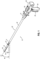
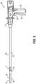
- FIGS. 1-7 depict an example of a surgical stapling and severing instrument (10) that is sized for insertion, in a nonarticulated state as depicted in FIG. 1 , through a trocar cannula, thoracotomy, or other incision to a surgical site in a patient for performing a surgical procedure.
- Instrument (10) of the present example includes a handle portion (20) connected to a shaft (22). Shaft (22) distally terminates in an articulation joint (11), which is further coupled with an end effector (12).
- end effector (12) is distal with respect to the more proximal handle portion (20).
- articulation joint (11) and/or articulation control (13) may be remotely articulated, as depicted in phantom in FIG. 1 , by an articulation control (13), such that end effector (12) may be deflected from the longitudinal axis (LA) of shaft (22) at a desired angle ( ⁇ ).
- articulation joint (11) and/or articulation control (13) may be constructed and operable in accordance with at least some of the teachings of U.S. Pat. No. 9,186,142, entitled “Surgical Instrument End Effector Articulation Drive with Pinion and Opposing Racks," issued on November 17, 2015 ; and/or U.S. Pat. No. 9,795,379, entitled “Surgical Instrument with Multi-Diameter Shaft,” issued October 24, 2017 .
- Other suitable forms that articulation joint (11) and articulation control (13) may take will be apparent to those skilled in the art in view of the teachings herein.
- End effector (12) of the present example includes a lower jaw (16) and an upper jaw in the form of a pivotable anvil (18).
- lower jaw (16) may be constructed and operable in accordance with at least some of the teachings of U.S. Pat. No. 9,808,248, entitled “Installation Features for Surgical Instrument End Effector Cartridge,” issued November 7, 2017 .
- Anvil (18) may be constructed and operable in accordance with at least some of the teachings of at least some of the teachings of U.S. Pat. No. 10,092,292, entitled “Staple Forming Features for Surgical Stapling Instrument,” issued October 9, 2018 .
- Other suitable forms that lower jaw (16) and anvil (18) may take will be apparent to those skilled in the art in view of the teachings herein.
- Handle portion (20) includes a pistol grip (24) and a closure trigger (26).
- Closure trigger (26) is pivotable toward pistol grip (24) to cause clamping, or closing, of the anvil (18) toward lower jaw (16) of end effector (12).
- Such closing of anvil (18) is provided through a closure tube (32) and a closure ring (33), which both longitudinally translate relative to handle portion (20) in response to pivoting of closure trigger (26) relative to pistol grip (24).
- Closure tube (32) extends along the length of shaft (22); and closure ring (33) is positioned distal to articulation joint (11).
- Articulation joint (11) is operable to transmit longitudinal movement from closure tube (32) to closure ring (33).
- Handle portion (20) also includes a firing trigger (28).
- An elongate member (not shown) longitudinally extends through shaft (22) and communicates a longitudinal firing motion from handle portion (20) to a firing beam (14) in response to actuation of firing trigger (28).
- This distal translation of firing beam (14) causes the stapling and severing of tissue clamped in end effector (12), as will be described in greater detail below.
- triggers (26, 28) may be released to release the tissue from end effector (12).
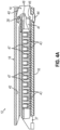
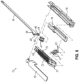
- firing beam (14) of the present example includes a transversely oriented upper pin (38), a firing beam cap (44), a transversely oriented middle pin (46), and a distally presented cutting edge (48).
- Upper pin (38) is positioned and translatable within a longitudinal anvil slot (42) of anvil (18).
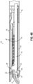
- Firing beam cap (44) slidably engages a lower surface of lower jaw (16) by having firing beam (14) extend through lower jaw slot (45) (shown in FIG. 4B ) that is formed through lower jaw (16).
- Middle pin (46) slidingly engages a top surface of lower jaw (16), cooperating with firing beam cap (44). Thereby, firing beam (14) affirmatively spaces end effector (12) during firing.
- firing beam (14) and/or associated lockout features may be constructed and operable in accordance with at least some of the teachings of U.S. Pat. No. 9,717,497, entitled “Lockout Feature for Movable Cutting Member of Surgical Instrument,” issued August 1, 2017 .
- Other suitable forms that firing beam (14) may take will be apparent to those skilled in the art in view of the teachings herein.
- FIG. 3 shows firing beam (14) of the present example proximally positioned and anvil (18) pivoted to an open position, allowing an unspent staple cartridge (37) to be removably installed into a channel of lower jaw (16).
- staple cartridge (37) of this example includes a cartridge body (70), which presents an upper deck (72) and is coupled with a lower cartridge tray (74).
- a vertical slot (49) is formed through part of staple cartridge (37).
- three rows of staple apertures (51) are formed through upper deck (72) on one side of vertical slot (49), with another set of three rows of staple apertures (51) being formed through upper deck (72) on the other side of vertical slot (49).
- a wedge sled (41) and a plurality of staple drivers (43) are captured between cartridge body (70) and tray (74), with wedge sled (41) being located proximal to staple drivers (43).
- Wedge sled (41) is movable longitudinally within staple cartridge (37); while staple drivers (43) are movable vertically within staple cartridge (37).
- Staples (47) are also positioned within cartridge body (70), above corresponding staple drivers (43).
- each staple (47) is driven vertically within cartridge body (70) by a staple driver (43) to drive staple (47) out through an associated staple aperture (51).
- wedge sled (41) presents inclined cam surfaces that urge staple drivers (43) upwardly as wedge sled (41) is driven distally through staple cartridge (37).
- staple cartridge (37) may be constructed and operable in accordance with at least some of the teachings of U.S. Pat. No. 9,517,065, entitled “Integrated Tissue Positioning and Jaw Alignment Features for Surgical Stapler,” issued December 13, 2016 .
- Other suitable forms that staple cartridge (37) may take will be apparent to those skilled in the art in view of the teachings herein.
- firing beam (14) is then advanced in engagement with anvil (18) by having upper pin (38) enter longitudinal anvil slot (42).
- a pusher block (80) (shown in FIG. 5 ) is located at the distal end of firing beam (14), and is configured to engage wedge sled (41) such that wedge sled (41) is pushed distally by pusher block (80) as firing beam (14) is advanced distally through staple cartridge (37) when firing trigger (28) is actuated.
- FIGS. 4A-4B depicts firing beam (14) fully distally translated after completing severing and stapling of tissue.
- staple forming pockets (53) are intentionally omitted from the view in FIGS. 4A-4B ; but staple forming pockets (53) are shown in FIG. 3 . It should also be understood that anvil (18) is intentionally omitted from the view in FIG. 5 .
- FIG. 7 shows end effector (12) having been actuated through a single stroke through tissue (90).
- cutting edge (48) (obscured in FIG. 7 ) has cut through tissue (90), while staple drivers (43) have driven three alternating rows of staples (47) through the tissue (90) on each side of the cut line produced by cutting edge (48).
- Staples (47) are all oriented substantially parallel to the cut line in this example, though it should be understood that staples (47) may be positioned at any suitable orientations.
- end effector (12) is withdrawn from the trocar after the first stroke is complete, spent staple cartridge (37) is replaced with a new staple cartridge, and end effector (12) is then again inserted through the trocar or incision to reach the stapling site for further cutting and stapling. This process may be repeated until the desired number of cuts and staples (47) have been provided.
- Anvil (18) may need to be closed to facilitate insertion and withdrawal through the trocar; and anvil (18) may need to be opened to facilitate replacement of staple cartridge (37).
- instrument (10) provides motorized control of firing beam (14).
- motorization may be provided in accordance with at least some of the teachings of U.S. Pat. No. 9,622,746, entitled “Distal Tip Features for End Effector of Surgical Instrument,” issued April 18, 2017 ; and/or U.S. Pat. No. 8,210,411, entitled “Motor-Driven Surgical Instrument,” issued July 3, 2012 .
- Other suitable components, features, and configurations for providing motorization of firing beam (14) will be apparent to those skilled in the art in view of the teachings herein. It should also be understood that some other versions may provide manual driving of firing beam (14), such that a motor may be omitted.
- instrument (10) may also include a manual return switch, or "bail out switch,” (104) (see, FIG. 8 ) positioned on or within handle portion (20), such as within or under a user-accessible panel or “bail out door” (30), the bail out switch (104) being configured to enable the operator to quickly begin retracting firing beam (14) proximally during a firing stroke.
- bail out switch (104) may be manually actuated when firing beam (14) has only been partially advanced distally.
- Bail out switch (104) may provide further functionality in accordance with at least some of the teachings of U.S. Pat. No. 9,622,746, entitled “Distal Tip Features for End Effector of Surgical Instrument," issued April 18, 2017 .
- the operator To access the bail out switch (104), the operator first opens the bailout door (30).
- various components are operable to translate firing beam (14) for stapling and severing clamped tissue via end effector (12).
- a motor is configured to activate to actuate end effector (12) in response to a firing actuation of firing trigger (28), first in a "forward" direction advance firing beam (14) distally to cut and staple tissue, and next in a "backward” direction to retract firing beam (14) proximally once the cutting and stapling has been completed.
- the motor is configured to deactivate.
- the motor can be controlled using a firing circuit and/or control algorithm to actuate end effector (12) at one or more predetermined speeds through the firing stroke, thereby providing a predetermined time period for completing the firing stroke.
- the predetermined time period may range from approximately 1 second in duration to approximately 10 seconds in duration. In other examples, the predetermined time period may range from approximately 3 seconds in duration to approximately 7 seconds in duration.
- instrument (10) provides motorized control of firing beam (14).
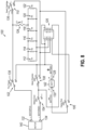
- FIG. 8 is an exemplary control circuit (100) that may be incorporated into instrument (10) to provide motorized control of firing beam (14).
- FIG. 8 shows an exemplary control circuit (100) that may be used to power an electric motor (140) with electric power from a battery (142).
- the motor (140) is operable to translate firing beam (14) longitudinally in a manner as will be described in greater detail below. It should be understood that the entire control circuit (100), including motor (140) and battery (142), may be housed within handle portion (20).
- motor (140) may be incorporated into instrument (10) in accordance with at least some of the teachings of U.S. Pat. No. 8,453,914 .
- control circuit (100) of this example includes several switches (102, 104, 106, 108, 110), several resistors (112, 114, 116, 118, 120, 122), a thermistor (124), and a relay (126), these components of which being configured and operable to selectively couple the positive and negative terminals (128, 130) of battery (142) with the positive and negative terminals (132, 134) of motor (140) to selectively power motor (140).
- control circuit (100) of the present example includes a fire trigger switch (102), which is configured to be actuated from the "3" position to the "2" position by an actuation firing trigger (28).
- Control circuit (100) also includes a bail out switch (104), which is configured to be actuated from the "2" position to the “3” position to effectively disconnect the negative motor terminal upon actuation of bail out switch (104).
- Control circuit (100) also includes a clamp switch (106), which is configured to be actuated from the "3" position to the "2” position upon a determination that anvil (18) has sufficiently closed to permit a safe and effective firing stroke.
- Control circuit (100) also includes a motor direction switch (108).
- switches (108, 136) automatically switch from first positions to second positions and relay (126) is latched "open,” thereby reversing the polarity of the voltage applied to motor terminals (132, 134). This reverses the direction of rotation of motor (140), it being understood that the operator will have released closure trigger (26) at this stage of operation.
- switch (108) Once actuation firing trigger (28) is released and fire trigger switch (102) is actuated back to the "3" position, relay (126) is latched “closed.” In some versions, current flows through a reverse direction indicator (e.g., including an optional LED, etc.) to provide a visual indication to the operator that motor (140) rotation has been reversed.
- a reverse direction indicator e.g., including an optional LED, etc.
- switch (108) may be automatically switched to a second position when firing beam (14) reaches a distal-most position will be apparent to those skilled in the art in view of the teachings herein.
- control circuit (100) includes spent cartridge switch (110), which is configured to be closed by default but is automatically opened in response to a lockout condition.
- a lockout condition may include one or more of the following: the absence of a cartridge (37) in lower jaw (16), the presence of a spent (e.g., previously fired) cartridge (37) in lower jaw (16), a determination that instrument (10) has been fired too many times, and/or any other suitable conditions.
- control circuit (100) is opened and thus motor (140) is inoperable when switch (110) is opened.
- a lockout indicator (110) e.g., an LED, etc.
- lockout switch (108) and associated components/functionality may be configured in accordance with at least some of the teachings of U.S. Pat. No. 7,644,848, entitled “Electronic Lockouts and Surgical Instrument Including Same,” issued Jan. 12, 2010 . While FIG.
- each switch (102, 104, 106, 108, 110) is independently operable to perform a specific function and is therefore variable depending on the circumstances of operation of instrument (10) in a particular instance.
- Resistors (112, 114, 116, 118, 120, 122) are operable to slow the initial stages of a firing stoke to allow time for spent cartridge switch (110) to operate, if necessary.
- Each resistor (112, 114, 116, 118, 120, 122) may be provided of equal value, for example, 47 ohms, or otherwise may be varied, or even omitted, as necessary.
- one or more of switches (102, 104, 106, 108, 110) are in the form of microswitches.
- Other suitable forms will be apparent to those skilled in the art in view of the teachings herein.
- at least part of control circuit (100) may be configured in accordance with at least some of the teachings of U.S. Pat. No. 8,210,411, entitled “Motor-Driven Surgical Instrument,” issued Jul. 3, 2012 .
- instrument (10) may be desirable to modify instrument (10) to incorporate a pulsating "forward" firing stroke technique operable to more slowly advance the cutting edge (48) of firing beam (14) into tissue.
- a pulsating "forward" firing stroke technique operable to more slowly advance the cutting edge (48) of firing beam (14) into tissue.
- various exemplary firing circuits can be included within instrument (10) to manipulate the power provided to motor (140) to successively activate and deactivate motor (140) during the "forward" cutting and stapling phase of the firing stroke thereby advancing the cutting edge (48) into the tissue in a pulsating manner. Thereafter, the control circuit may be operable to disable or otherwise bypass the pulsing portion of the firing circuit during the "backward" phase of the firing stroke to allow motor (140) to activate to retract firing beam (14) proximally through lower jaw (16) in one continuous motion (i.e., without pulsing).
- motor (140) can be controlled using a firing circuit and/or control algorithm to actuate end effector (12) at one or more predetermined speeds through the firing stroke having a pulsating forward phase, thereby providing a longer predetermined time period for completing the firing stroke than in non-pulsating examples.
- the predetermined time period to complete a full firing stroke may range from approximately 2 seconds in duration to approximately 18 seconds in duration. In other examples, the predetermined time period may range from approximately 6 seconds in duration to approximately 14 seconds in duration.
- the predetermined time period for only the forward phase of the firing stroke may range from approximately 2 seconds in duration to approximately 10 seconds in duration. In other examples, the time period for only the forward phase of the firing stroke may range from approximately 3 seconds in duration to approximately 7 seconds in duration.
- Various factors may affect the time period required to complete the forward phase, such as friction, battery level, and cartridge (37) size. Additionally, motor (140) may require more activation cycles, thus a greater predetermined time period, for cutting and stapling procedures involving thick tissue than motor (140) does for thin tissue.
- motor (140) may pulse (i.e., transition from an OFF or deactivated state to an ON or activated state) 3-4 times over the course of 3 seconds for cutting and stapling thin tissue, while motor (140) may pulse 7-9 times over the course of 7 seconds for cutting and stapling thick tissue.
- control circuit (100) may be readily used with instrument (10). It should also be understood that, in some instances, the configuration and arrangement of the electrical components of control circuit (100) may need to be varied in order to complement the configuration and arrangement of the alternative firing circuits described below. Various suitable ways in which the alternatives to control circuit (100) described below may be incorporated into instrument (10) will be apparent to those skilled in the art in view of the teachings herein.
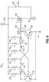
- FIG. 9 depicts one exemplary pulsating firing circuit (150) which can be coupled with control circuit (100), or otherwise integrated into control circuit (100).
- node (152) of circuit (150) may be coupled with node (136) of control circuit (100)
- node (154) of circuit (150) may be coupled with node (138) of control circuit (100) to include cutting edge (48) pulsing techniques to instrument (10).
- firing circuit (150) of this example includes several resistors (156, 158, 160, 162, 164, 166, 168), diodes (170, 172), capacitors (174, 176), transistors (178, 180, 182), and switch (184).
- transistors (178, 180) may each be an NPN bipolar junction transistor, for example, a 2N3904 General Purpose Transistor manufactured by ON Semiconductor, Inc. Alternatively, any other suitable kinds of transistors may be used.
- Diodes (170, 172) can be, for example, 1N4148 Small Signal Diodes manufactured by ON Semiconductor, Inc. Alternatively, any other suitable kinds of diodes may be used.
- resistors (156, 158, 160, 162, 164, 166, 168) of the present example can be chosen at 470 ohms, 390 ohms, 12.5 kiloohms, 12.5 kiloohms, 390 ohms, 470 ohms, and 470 ohms, respectively. Alternatively, any other resistance values may be used.
- Capacitors (174, 176) can be chosen at 115 microfarads and 58 microfarads, respectively. Alternatively, any other capacitance values may be used.
- Firing circuit (150) is thereby configured and operable as an astable multi-vibrator circuit to output a square wave voltage signal, consisting of alternating HIGH and LOW voltage outputs, to node (186) which are formed by alternate switching of transistors (178. 180), where the peak amplitude of the HIGH voltage output signal is approximately equal to the amplitude of input signal at node (154).
- Transistor (182) can be a MOSFET transistor, for example, an SIS476DN-T1-GE3 N-Channel 30 V (D-S) MOSFET manufactured by Vishay Intertechnology, Inc. Alternatively, any other suitable kind of transistor may be used.
- Transistor (182) can be provided to selectively allow electrical current to pass between nodes (152, 154) as the astable multi-vibrator output square waveform remains in the HIGH state at node (186), and disallow electrical current to pass between nodes (152, 154) as the astable multi-vibrator output square waveform remains in the LOW state at node (186).
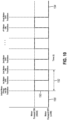
- FIG. 10 depicts an example voltage output waveform received at node (186) of FIG. 9 .
- firing circuit (150) is powered upon receiving a power signal from positive battery terminal (130) initiated in part by an actuation of fire trigger switch (102). Unless and until firing circuit (150) receives a power signal, the output waveform at node (186) will remain at a LOW state as shown in initial phase (188).
- the astable multi-vibrator circuitry i.e., resistors (156, 158, 160, 162, 164, 166), capacitors (174, 176), diodes (170. 172), and transistors (178. 180)
- the astable multi-vibrator circuitry i.e., resistors (156, 158, 160, 162, 164, 166), capacitors (174, 176), diodes (170. 172), and transistors (178. 180)
- the astable multi-vibrator circuitry i.e., resistors (156, 158,
- the cutting edge (48) may be desirable to pulse the cutting edge (48) forward in two pulses, therefore any number of square wave periods ranging from approximately 1.5 periods to approximately 2.0 periods. In other examples it may be desirable to pulse the cutting edge (48) forward in three or more pulses, therefore requiring approximately 2.5 or more square wave periods. It may be further desirable to modify the length of a time period (192) of signal (190).
- the frequency of signal (190) ranges from approximately 0.5 hertz to approximately 3.0 hertz. In alternative examples, the frequency of signal (190) may range from approximately 0.75 hertz to approximately 2.0 hertz.
- the frequency of signal (190) may be at or approximately 1.5 hertz (i.e., 1.5 seconds in length, 1.0 seconds HIGH and 0.5 seconds LOW).
- resistor (156, 158, 160, 162, 164, 166) and capacitor (174, 176) values may be altered to adjust time period (192) as required.
- the duty cycle of signal (190) is approximately 50%, in various other examples the duty cycle of signal (190) may be selected to be 0%, 25%, 75%, 100%, or some other value. However, it should be understood that various alternative duty cycles may be configured.
- firing circuit (150) is not utilized to provide power to motor (140) to retract the cutting edge (48) from the tissue. Rather, once the cutting operating is complete, motor direction switch (108) of control circuit (100) toggles from the first state to the second state, causing the power signal to be removed from node (154), such that the output provided at node (152) of firing circuit (150) returns to a LOW state (194).
- a bypass mechanism to permit an operator of instrument (10) to bypass the pulse-inducing features of firing circuit (150), such as in an instance where the operator wishes to cut a vessel or for any other reason dictated by the circumstances, and instead advance the cutting edge (48) in one continuous motion (i.e., via signal (190) having a duty cycle of 100%) as shown in FIG. 8 .
- a user-actuatable bypass switch (184) for example an ON/OFF rocker switch or other switch form commonly used in the art that is easily actual by a user, may be included on an exterior surface of instrument (10), such as on handle portion (20) of instrument (10).
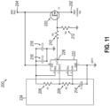
- FIGS. 11-12 depict another exemplary firing circuit (200) that may be incorporated into instrument (10).
- node (202) of circuit (200) may be coupled with node (136) of control circuit (100)
- node (204) of circuit (200) may be coupled with node (138) of control circuit (100) to include cutting edge (48) pulsing techniques to instrument (10).
- firing circuit (200) of this example includes several resistors (206, 208, 210, 212), capacitors (214, 216, 218), a transistor (220), and a timer (222).
- Transistor (220) can be a MOSFET transistor, for example, an SIS476DN-T1-GE3 N-Channel 30 V (D-S) MOSFET manufactured by Vishay Intertechnology, Inc. Alternatively, any other suitable kind of transistor may be used.
- timer (222) can be, for example, a LMC555 CMOS Low-Power Timer manufactured by Texas Instruments, Inc. It will be appreciated that in other examples timer (222) may take various other suitable forms apparent to those skilled in the art in view of the teachings herein.
- Timer (222) of the present example is a single integrated chip functioning similar to a multi-vibrator. Timer (222) is operable in three different modes: astable mode, bistable mode, and monostable mode. In astable mode, as will be described below, timer (222) outputs an oscillating pulse signal or waveform. Particularly, output (226) of timer (222) oscillates between a HIGH state and a LOW state at a configurable frequency and pulse width. At the conclusion of the adjustable duration, timer (222) returns to a steady LOW state output unless and until the external trigger activates timer (222) again. Thus, output (226) is configurable to resemble the waveform illustrated in FIG. 10 .
- RC circuit (224) comprising resistors (206, 208) and capacitor (214), is configurable by changing the resistor (206, 208) and capacitor (214) values to adjust the oscillating square waveform provided at an output (226) of the timer (222).
- resistors (206, 208, 210, 212) can be chosen at 22 kiloohms, 16 kiloohms, 470 ohms, and 10 kiloohms, respectively. Alternatively, any other suitable resistance values may be used.
- Capacitors (214, 216, 218) can be chosen at 47 microfarads, 0.01 microfarads, and 1 microfarad, respectively. Alternatively, any other suitable kinds of capacitor values may be used.
- transistor (182) can further be provided to selectively allow electrical current to pass between nodes (202, 204) as the output square waveform remains in the HIGH state at node (226), and disallow electrical current to pass between nodes (202, 204) as the astable multi-vibrator output square waveform remains in the LOW state at node (226).
- the cutting edge (48) of firing beam (14) may be desirable to pulse the cutting edge (48) of firing beam (14) forward in two pulses, therefore requiring 1.5 - 2 square wave periods. In other examples it may be desirable to pulse the cutting edge (48) forward in three or more pulses, therefore requiring 2.5 or more square wave periods. It may be further desirable to modify the length of one period (192) of signal (190). In the present example, a single period (192) may be one second in length (i.e., 0.5 seconds HIGH, 0.5 seconds LOW). In other examples, values of RC circuit (224) may be altered to adjust period (192) as required. In various examples, the duty cycle of signal (190) may be selected to be 0%, 25%, 50%, 75%, 100%; however, it should be understood that various alternative duty cycles may be configured.
- firing circuit (200) is not utilized to provide power to motor (140) to retract the cutting edge (48) from the tissue. Rather, once the cutting operating is complete, motor direction switch (108) of control circuit (100) toggles from the first state to the second state, causing the power signal to be removed from node (204), such that the output provided at node (226) of firing circuit (200) returns to a LOW state (194).
- FIG. 12 shows an example of firing circuit (200) that provides a user with the real-time ability to adjust the values of resistors (206, 208) described above.
- resistors (206, 208) may be substituted with potentiometers (230, 232).
- Potentiometers (230, 232) may be actuatable via one or more user-adjustable dials which may be included on instrument (10), such as on handle portion (20) of instrument (10).
- potentiometer (230) may be adjustable from 1-30 kiloohms and potentiometer (232) may be adjustable from 1-25 kiloohms.
- potentiometers (230, 232) may be varied in order to meet the requirements of alternative configurations of instrument (10).
- circuit (200) of the present example can include a bypass mechanism to permit an operator of instrument (10) to bypass the pulse-inducing features of firing circuit (200) and instead advance cutting edge (48) of firing beam (14) in one continuous motion (i.e., via signal (190) having a duty cycle of 100%), such as shown in FIG. 8 .
- a user-actuatable bypass switch (234) for example an ON/OFF rocker switch or other switch form commonly used in the art that is easily actuated by a user, may be included on an exterior surface of instrument (10), such as on handle portion (20) of instrument (10).
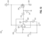
- FIGS. 13-14 depict another exemplary firing circuit (300) that may be incorporated into instrument (10).
- node (302) of circuit (300) may be coupled with node (136) of control circuit (100)
- node (304) of circuit (300) may be coupled with node (138) of control circuit (100) to include cutting edge (48) pulsing techniques to instrument (10).
- firing circuit (300) of this example includes several resistors (306, 308, 310, 312, 314), a capacitor (316), a transistor (318), and an operational amplifier (320).
- Transistor (220) can be a MOSFET transistor, for example, an SIS476DN-T1-GE3 N-Channel 30 V (D-S) MOSFET manufactured by Vishay Intertechnology, Inc.
- operational amplifier (320) can be, for example, an SG1536Y High Voltage Operational Amplifier manufactured by Microsemi Corporation. It will be appreciated that in other examples operational amplifier (320) may take various other suitable forms apparent to those skilled in the art in view of the teachings herein.
- Operational amplifier (320) of the present example is configured to operate similar to a multi-vibrator to output an oscillating pulse signal or waveform.
- output (322) of operational amplifier (320) oscillates between a HIGH state and a LOW state at a configurable frequency and pulse width.
- operational amplifier (320) returns to a steady LOW state output.
- output (322) is configurable to resemble the waveform illustrated in FIG. 10 .
- an RC circuit comprising resistors (306, 308, 310) and capacitor (316) is configurable by varying the resistor (306, 308, 310) and capacitor (316) values to adjust the oscillating square waveform provided at an output (322) of the operational amplifier (320).
- resistors (306, 308, 310) can be chosen at 0.2 megaohms, 27 kiloohms, and 27 kiloohms, respectively, and capacitor (316) can be chosen at 0.47 microfarads.
- any other suitable kinds of resistance and capacitance values may be used.
- transistor (318) can further be provided to selectively allow electrical current to pass between nodes (302, 304) as the output square waveform remains in the HIGH state at node (322), and disallow electrical current to pass between nodes (302, 304) as the multi-vibrator (i.e., the operation amplifier along with the RC circuit) output square waveform remains in the LOW state at node (322).
- the duty cycle of signal (190) may be selected to be 0%, 25%, 50%, 75%, 100%; however, it should be understood that various alternative duty cycles may be configured.
- firing circuit (300) is not utilized to provide power to motor (140) to retract the cutting edge (48) from the tissue. Rather, once the cutting operating is complete, motor direction switch (108) of control circuit (100) toggles from the first state to the second state, causing the power signal to be removed from node (304), such that the output provided at node (322) of firing circuit (300) returns to a LOW state (194).
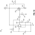
- FIG. 14 shows an example of firing circuit (300) that provides a user with the real-time ability to adjust the values of resistor (306) described above.
- resistor (306) may be substituted with a potentiometer (330).
- Potentiometer (330) may be actuatable via one or more user-adjustable dials which may be included on instrument (10), such as on handle portion (20) of instrument (10).
- potentiometer (330) may be adjustable from 1 - 30 kiloohms and potentiometer (232) may be adjustable from 2 kiloohms - 20 megaohms. However, it should be understood that the values of potentiometer (330) may be varied in order to meet the requirements of alternative configurations of instrument (10).
- circuit (300) of the present example can include a bypass mechanism to permit an operator of instrument (10) to bypass the pulse-inducing features of firing circuit (300) and instead advance the cutting edge (48) of firing beam (14) in one continuous motion (i.e., via signal (190) having a duty cycle of 100%), such as shown in FIG. 8 .
- a user-actuatable bypass switch (332) for example an ON/OFF rocker switch or other switch form commonly used in the art that is easily actuated by a user, may be included on an exterior surface of instrument (10), such as on handle portion (20) of instrument (10).
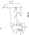
- FIG. 15 depicts another exemplary firing circuit (400) that may be incorporated into instrument (10).
- node (402) of circuit (400) may be coupled with node (136) of control circuit (100)
- node (404) of circuit (400) may be coupled with node (138) of control circuit (100) to include cutting edge (48) pulsing techniques to instrument (10).
- firing circuit (400) of this example includes resistors (406, 408), a transistor (410), and a relay (320).
- Transistor (410) can be a MOSFET transistor, for example, an S1S476DN-T1-GE3 N-Channel 30 V (D-S) MOSFET manufactured by Vishay Intertechnology, Inc.
- relay (412) can be, for example, an H3FA Solid State Timer manufactured by OMRON Corp. Alternatively, any other suitable kind of relay may be used. It will be appreciated that in other examples relay (412) may take various other suitable forms apparent to those skilled in the art in view of the teachings herein.
- Relay (412) of the present example is configured to operate similar to a multi-vibrator to output an oscillating pulse signal or waveform.
- output (414) of relay (412) oscillates between a HIGH state and a LOW state at a configurable frequency and pulse width.
- relay (412) returns to a steady LOW state output unless and until the external trigger activates relay (412) again.
- output (414) is configurable to resemble the waveform illustrated in FIG. 10 .
- relay (412) includes one or more inputs or time range selectors (416, 418, 420) that are user-adjustable to vary the oscillating square waveform provided at an output (414) of relay (412).
- resistors (406, 408) can be chosen at 470 ohms, 10 kiloohms, respectively.
- transistor (410) can further be provided to selectively allow electrical current to pass between nodes (402, 404) as the output square waveform remains in the HIGH state at node (414), and disallow electrical current to pass between nodes (402, 404) as the multi-vibrator (i.e., the operation amplifier along with the RC circuit) output square waveform remains in the LOW state at node (414).
- the duty cycle of signal (190) may be selected to be 0%, 25%, 50%, 75%, 100%; however, it should be understood that various alternative duty cycles may be configured.
- firing circuit (400) is not utilized to provide power to motor (140) to retract the cutting edge (48) from the tissue. Rather, once the cutting operating is complete, motor direction switch (108) of control circuit (100) toggles from the first state to the second state, causing the power signal to be removed from node (204), such that the output provided at node (414) of firing circuit (400) returns to a LOW state (194).
- firing circuit (400) can include a user-actuatable bypass switch (422).
- Bypass switch (422) may be in the physical form of an ON/OFF rocker switch, or other switch form commonly used in the art that is easily actuated by a user, that is included on an exterior surface of instrument (10), such as on handle portion (20) of instrument (10).
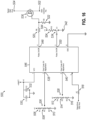
- FIG. 16 depicts another exemplary firing circuit (500) that may be incorporated into instrument (10).
- node (502) of circuit (500) may be coupled with node (136) of control circuit (100)
- node (504) of circuit (500) may be coupled with node (138) of control circuit (100) to include cutting edge (48) techniques to instrument (10).
- firing circuit (500) of this example includes resistors (506, 510, 512, 516, 518, 520, 522, 524), potentiometers (508, 514), capacitors (530, 532), a switch (534), a transistor (536), and a microcontroller (546).
- Transistor (536) can be a MOSFET transistor, for example, an SIS476DN-T1-GE3 N-Channel 30 V (D-S) MOSFET manufactured by Vishay Intertechnology, Inc. Alternatively, any other suitable kind of transistor may be used.
- microcontroller (546) can be, for example, a PIC12F1501 8-Pin Flash, 8-Bit Microcontroller manufactured by Microchip Technology, Inc. It will be appreciated that in other examples microcontroller (546) may take various other suitable forms apparent to those skilled in the art in view of the teachings herein.
- Microcontroller (546) of the present example is configured to operate similar to a multi-vibrator to output an oscillating pulse signal or waveform.
- the signal at output node (548) of microcontroller (546) oscillates between a HIGH state and a LOW state at a configurable frequency and pulse width.
- microcontroller (546) returns to a steady LOW state output unless and until the external trigger activates relay (412) again.
- the signal at output node (548) of microcontroller (546) is thus configurable to resemble the waveform illustrated in FIG. 10 .
- the duty cycle of signal (190) may be selected to be 0%, 25%, 50%, 75%, 100%; however, it should be understood that various alternative duty cycles may be configured.
- microcontroller (546) includes one or more inputs, ON duty cycle adjuster (538) and OFF duty cycle adjuster (540), that are user-adjustable to vary the oscillating square waveform provided in the signal at output node (548) of microcontroller (546). More specifically, resistors (506, 510) in combination with potentiometer (508) form a variable voltage divider operable to vary the input voltage to ON duty cycle adjuster (538) to adjust the duration of the HIGH states of the signal at output node (548).
- resistors (512, 516) in combination with potentiometer (514) form a variable voltage divider operable to vary the input voltage to OFF duty cycle adjuster (540) to adjust the duration of the LOW states of the signal at output node (548).
- Potentiometers (508, 514) may be in the physical form of a user-adjustable dial, or other variable mechanism commonly used in the art that is easily actuated by a user, that is included on an exterior surface of instrument (10), such as on handle portion (20) of instrument (10).
- resistors (506, 510, 512, 516, 518, 520, 522, 524), can be chosen at 1 kiloohms, 1 kiloohms, 1 kiloohms, 1 kiloohms, 470 ohms, 470 ohms, 10 kilohms, and 10 kilohms, respectively.
- Capacitors (530, 532) can be chosen to be 0.1 microfarads and 1.0 microfarads, respectively. However, it should be understood that all electrical component values may be varied in order to meet the requirements of alternative configurations of instrument (10).
- transistor (536) can further be provided to selectively allow electrical current to pass between nodes (502, 504) as the output square waveform remains in the HIGH state at output node (548), and disallow electrical current to pass between nodes (502, 504) as the multi-vibrator (i.e., the operation amplifier along with the RC circuit) output square waveform remains in the LOW state at output node (548).
- firing circuit (500) is not utilized to provide power to motor (140) to retract the cutting edge (48) from the tissue. Rather, once the cutting operating is complete, motor direction switch (108) of control circuit (100) toggles from the first state to the second state, causing the power signal to be removed from node (502), such that the output signal provided at output node (548) of firing circuit (500) returns to a LOW state (194).
- firing circuit (500) can include a user-actuatable bypass switch (534) coupled with microcontroller (546) at output node (550) and configured to selectively disable pulsing features.
- bypass switch (534) when bypass switch (534) is coupled with ground (542), microcontroller (546) can be configured to bypass the pulsing features and instead provide a signal at output node (548) a steady "one-shot” or monostable electrical pulse to motor (140) upon actuation of closure trigger (26).
- bypass switch (534) when bypass switch (534) is coupled with a battery or power supply voltage (544) through resistor (524), microcontroller (546) can be configured to enable the pulsing features and provide a signal at output node (548) an oscillating or astable electrical pulse to motor (140) upon actuation of closure trigger (26).
- Bypass switch (534) may be in the physical form of an ON/OFF rocker switch, or other switch form commonly used in the art that is easily actuated by a user, that is included on an exterior surface of instrument (10), such as on handle portion (20) of instrument (10).
- control circuit (100) may be readily used with instrument (10). It should also be understood that, in some instances, the configuration and arrangement of the electrical components of control circuit (100) and firing circuits (150, 200, 300, 400, 500) may need to be varied in order to complement the configuration and arrangement of the features of instrument (10) described herein. Various suitable ways in which the alternatives to control circuit (100) and firing circuits (150, 200, 300, 400, 500) described herein may be incorporated into instrument (10) will be apparent to those skilled in the art in view of the teachings herein.
- Versions of the devices described above may have application in conventional medical treatments and procedures conducted by a medical professional, as well as application in robotic-assisted medical treatments and procedures.
- various teachings herein may be readily incorporated into a robotic surgical system such as the DAVINCI TM system by Intuitive Surgical, Inc., of Sunnyvale, California.
- Versions of the devices described above may be designed to be disposed of after a single use, or they can be designed to be used multiple times. Versions may, in either or both cases, be reconditioned for reuse after at least one use. Reconditioning may include any combination of the steps of disassembly of the device, followed by cleaning or replacement of particular pieces, and subsequent reassembly. In particular, some versions of the device may be disassembled, and any number of the particular pieces or parts of the device may be selectively replaced or removed in any combination. Upon cleaning and/or replacement of particular parts, some versions of the device may be reassembled for subsequent use either at a reconditioning facility, or by a user immediately prior to a procedure.
- reconditioning of a device may utilize a variety of techniques for disassembly, cleaning/replacement, and reassembly. Use of such techniques, and the resulting reconditioned device, are all within the scope of the present application.
- versions described herein may be sterilized before and/or after a procedure.
- the device is placed in a closed and sealed container, such as a plastic or TYVEK bag.
- the container and device may then be placed in a field of radiation that can penetrate the container, such as gamma radiation, x-rays, or high-energy electrons.
- the radiation may kill bacteria on the device and in the container.
- the sterilized device may then be stored in the sterile container for later use.
- a device may also be sterilized using any other technique known in the art, including but not limited to beta or gamma radiation, ethylene oxide, or steam.
Landscapes
- Health & Medical Sciences (AREA)
- Life Sciences & Earth Sciences (AREA)
- Surgery (AREA)
- Heart & Thoracic Surgery (AREA)
- Engineering & Computer Science (AREA)
- Biomedical Technology (AREA)
- Nuclear Medicine, Radiotherapy & Molecular Imaging (AREA)
- Medical Informatics (AREA)
- Molecular Biology (AREA)
- Animal Behavior & Ethology (AREA)
- General Health & Medical Sciences (AREA)
- Public Health (AREA)
- Veterinary Medicine (AREA)
- Surgical Instruments (AREA)
Claims (16)
- Chirurgisches Instrument (10), umfassend:(a) einen Körper (20), der einen Auslöseaktuator (28) einschließt;(b) einen Schaft (22), der sich distal von dem Körper (20) erstreckt;(c) einen Motor (140), der ausgestaltet ist, um mit einer Leistungsquelle (142) zu koppeln, wobei der Motor (140) ausgestaltet ist, um in Reaktion auf eine Auslösebetätigung des Auslöseaktuators (28) aktiviert zu werden;(d) einen Endeffektor (12), der an einem distalen Ende des Schafts (22) angeordnet ist, wobei der Endeffektor (12) funktionell ist, um Gewebe zu klammern und zu durchtrennen, wobei der Endeffektor (12) eine Schneidkante (48) einschließt, die ausgestaltet ist, um selektiv in Längsrichtung zwischen einer proximalen Position und einer distalen Position zu translatieren, wobei die Schneidkante (48) ausgestaltet ist, um in Reaktion auf eine Aktivierung des Motors (140) von der proximalen Position in die distale Position überzugehen, um Gewebe zu schneiden; und(e) eine Steuerschaltung (100), die funktionell mit dem Motor (140) und dem Auslöseaktuator (28) gekoppelt ist, wobei die Steuerschaltung (100) ausgestaltet ist, um in Reaktion auf die Auslösebetätigung ein Vorwärts-Motorsteuersignal zu generieren, um den Motor (140) zu aktivieren, wobei das Vorwärts-Motorsteuersignal ausgestaltet ist, um die Schneidkante (48) über einen vorbestimmten Zeitraum von der proximalen Position zu der distalen Position zu pulsieren, um das Gewebe zu schneiden, wobei das pulsierende Vorwärts-Motorsteuersignal einschließt:(i) eine erste Zeitdauer, die Bewegung der Schneidkante (48) nach distal aus der proximalen Position zu einer zweiten Längsposition einschließt,(ii) eine zweite Zeitdauer, die beendete Bewegung der Schneidkante (48) einschließt, wobei die zweite Zeitdauer der ersten Zeitdauer folgt, und(iii) eine dritte Zeitdauer, die Bewegung der Schneidkante (48) nach distal aus der zweiten Längsposition in Richtung der distalen Position einschließt, wobei die dritte Zeitdauer der zweiten Zeitdauer folgt.
- Chirurgisches Instrument nach Anspruch 1, wobei die Steuerschaltung (100) ausgestaltet ist, um zu bestimmen, dass die Schneidkante (48) die distale Position erreicht hat, wobei die Steuerschaltung (100) des Weiteren ausgestaltet ist, um ein Umkehr-Motorsteuersignal zu generieren, um den Motor (140) zu aktivieren, um die Schneidkante (48) aus der distalen Position wieder in die proximale Position übergehen zu lassen.
- Chirurgisches Instrument nach Anspruch 2, wobei die Steuerschaltung (100) des Weiteren einen Schalter (108) einschließt, der funktionell ist, um eine elektrische Polarität umzukehren, die dem Motor (140) durch die Leistungsquelle (142) bereitgestellt wird, wobei die Steuerschaltung (100) ausgestaltet ist, um den Schalter (108) in Reaktion auf die Bestimmung zu bedienen, dass die Schneidkante (48) die distale Position erreicht hat.
- Chirurgisches Instrument nach Anspruch 1, wobei die Steuerschaltung (100) des Weiteren aus analogen elektrischen Komponenten zusammengesetzt ist, wobei die analogen elektrischen Komponenten ausgestaltet sind, um das Vorwärts-Motorsteuersignal zwischen einem Hochspannungssignal und einem Niederspannungssignal zu oszillieren, wobei das Hochspannungssignal funktionell ist, um den Motor (140) zu aktivieren, wobei das Niederspannungssignal funktionell ist, um den Motor (140) zu deaktivieren.
- Chirurgisches Instrument nach Anspruch 4, wobei die analogen elektrischen Komponenten des Weiteren eine RC-Schaltung, gekoppelt mit zwei Transistoren (178, 180), umfassen, wobei die RC-Schaltung mindestens einen Widerstand und mindestens einen Kondensator einschließt, wobei die RC-Schaltung und zwei Transistoren (178, 180) ausgestaltet sind, um das Vorwärts-Motorsteuersignal zu oszillieren.
- Chirurgisches Instrument nach Anspruch 4, wobei die analogen elektrischen Komponenten des Weiteren eine integrierte Schaltung als Zeitgebervorrichtung (222) umfassen.
- Chirurgisches Instrument nach Anspruch 4, wobei die analogen elektrischen Komponenten des Weiteren einen Operationsverstärker (320) umfassen, der ausgestaltet ist, um das Vorwärts-Motorsteuersignal zu oszillieren.
- Chirurgisches Instrument nach Anspruch 4, wobei die analogen elektrischen Komponenten des Weiteren ein variables Zeitgeberrelais (412) umfassen, das ausgestaltet ist, um das Vorwärts-Motorsteuersignal zu oszillieren.
- Chirurgisches Instrument nach Anspruch 1, wobei der Körper (20) des Weiteren einen Schließ-Aktuator (26) einschließt, wobei der Endeffektor (12) des Weiteren eine Klammerbaugruppe (16, 18) einschließt, die ausgestaltet ist, um sich in Reaktion auf eine Betätigung des Schließ-Aktuators (26) selektiv zwischen einer offenen Position und einer geschlossenen Position zu bewegen, wobei die Klammeranordnung (16, 18) ausgestaltet ist, um in Reaktion auf eine Aktivierung des Motors (140) eine Vielzahl von Klammern (47) aus der Klammerbaugruppe (16, 18) in das Gewebe zu treiben.
- Chirurgisches Instrument nach Anspruch 1, wobei die Steuerschaltung (100) des Weiteren einen Mikrocontroller (546) einschließt, wobei der Mikrocontroller (546) ausgestaltet sind, um das Vorwärts-Motorsteuersignal zwischen einem Hochspannungssignal und einem Niederspannungssignal zu oszillieren, wobei das Hochspannungssignal funktionell ist, um den Motor (140) zu aktivieren, wobei das Niederspannungssignal funktionell ist, um den Motor (140) zu deaktivieren.
- Chirurgisches Instrument nach Anspruch 1, wobei das Vorwärts-Motorsteuersignal mit einem Lastzyklus von weniger als 100 % ausgestaltet ist, um die Schneidkante (48) aus der proximalen Position in die distale Position zu pulsieren, um Gewebe zu schneiden, wobei die Steuerschaltung (100) des Weiteren einen Umgehungsschalter (184) einschließt, wobei der Umgehungsschalter (184) selektiv betätigbar ist, um den Lastzyklus auf 100 % zu erhöhen.
- Chirurgisches Instrument nach Anspruch 11, wobei der Umgebungsschalter (184) auf einer Außenoberfläche des Körpers (20) positioniert ist.
- Chirurgisches Instrument nach Anspruch 1, wobei das Vorwärts-Motorsteuersignal mit einem Lastzyklus von weniger als 100 % ausgestaltet ist, um die Schneidkante (48) aus der proximalen Position in die distale Position zu pulsieren, um Gewebe zu schneiden, wobei die Steuerschaltung (100) des Weiteren ein anpassbares Eingabemerkmal einschließt, wobei das anpassbare Eingabemerkmal selektiv bedienbar ist, um den Lastzyklus anzupassen.
- Chirurgisches Instrument nach Anspruch 13, wobei das anpassbare Eingabemerkmal auf einer Außenoberfläche des Körpers (20) positioniert ist.
- Chirurgisches Instrument nach Anspruch 1, wobei das Vorwärts-Motorsteuersignal mit einem Lastzyklus von 50 % ausgestaltet ist, um die Schneidkante (48) aus der proximalen Position zu der distalen Position zu pulsieren, um Gewebe zu schneiden.
- Chirurgisches Instrument nach Anspruch 1, wobei das Vorwärts-Motorsteuersignal eine Frequenz im Bereich von annähernd 0,5 Hertz bis annähernd 3 Hertz einschließt.
Applications Claiming Priority (2)
| Application Number | Priority Date | Filing Date | Title |
|---|---|---|---|
| US16/930,613 US12193662B2 (en) | 2020-07-16 | 2020-07-16 | Firing circuit and control algorithm for surgical stapler |
| PCT/IB2021/056392 WO2022013805A1 (en) | 2020-07-16 | 2021-07-15 | Firing circuit and control algorithm for surgical stapler |
Publications (3)
| Publication Number | Publication Date |
|---|---|
| EP3998961A1 EP3998961A1 (de) | 2022-05-25 |
| EP3998961C0 EP3998961C0 (de) | 2023-11-15 |
| EP3998961B1 true EP3998961B1 (de) | 2023-11-15 |
Family
ID=76971957
Family Applications (1)
| Application Number | Title | Priority Date | Filing Date |
|---|---|---|---|
| EP21743273.1A Active EP3998961B1 (de) | 2020-07-16 | 2021-07-15 | Auslöseschaltung und steueralgorithmus für chirurgisches klammergerät |
Country Status (6)
| Country | Link |
|---|---|
| US (2) | US12193662B2 (de) |
| EP (1) | EP3998961B1 (de) |
| JP (1) | JP7779455B2 (de) |
| CN (1) | CN116133600B (de) |
| BR (1) | BR112023000709A2 (de) |
| WO (1) | WO2022013805A1 (de) |
Families Citing this family (4)
| Publication number | Priority date | Publication date | Assignee | Title |
|---|---|---|---|---|
| US12193662B2 (en) * | 2020-07-16 | 2025-01-14 | Cilag Gmbh International | Firing circuit and control algorithm for surgical stapler |
| US11931029B2 (en) | 2022-03-23 | 2024-03-19 | Cilag Gmbh International | Firing limit feature for powered surgical stapler |
| CN119652170A (zh) * | 2023-09-15 | 2025-03-18 | 江苏风和医疗器材股份有限公司 | 电机控制电路及外科器械 |
| CN119652171A (zh) * | 2023-09-15 | 2025-03-18 | 江苏风和医疗器材股份有限公司 | 电机控制电路、系统及外科器械 |
Family Cites Families (43)
| Publication number | Priority date | Publication date | Assignee | Title |
|---|---|---|---|---|
| US4114071A (en) * | 1976-10-18 | 1978-09-12 | Herbert T. Thrower, Jr. | Light modulator system |
| ES2048231T3 (es) * | 1989-05-19 | 1994-03-16 | Siemens Ag | Disposicion de circuito para el control de un aparato electrico de terapia, especialmente un aparato de cirugia-hf. |
| US5479153A (en) * | 1993-10-26 | 1995-12-26 | Hankscraft Motors, Inc. | Method and apparatus for displaying an object |
| US6716233B1 (en) * | 1999-06-02 | 2004-04-06 | Power Medical Interventions, Inc. | Electromechanical driver and remote surgical instrument attachment having computer assisted control capabilities |
| JP3718830B2 (ja) | 2001-02-26 | 2005-11-24 | 株式会社日立製作所 | 電力変換装置 |
| GB2369730B (en) | 2001-08-30 | 2002-11-13 | Integrated Syst Tech Ltd | Illumination control system |
| US7434715B2 (en) | 2003-09-29 | 2008-10-14 | Ethicon Endo-Surgery, Inc. | Surgical stapling instrument having multistroke firing with opening lockout |
| JP4956422B2 (ja) | 2004-04-27 | 2012-06-20 | エマーソン エレクトリック カンパニー | 食品廃棄物ディスポーザの詰り排除装置および方法 |
| US8579176B2 (en) | 2005-07-26 | 2013-11-12 | Ethicon Endo-Surgery, Inc. | Surgical stapling and cutting device and method for using the device |
| US8038046B2 (en) * | 2006-05-19 | 2011-10-18 | Ethicon Endo-Surgery, Inc. | Electrical surgical instrument with optimized power supply and drive |
| US7770775B2 (en) | 2006-01-31 | 2010-08-10 | Ethicon Endo-Surgery, Inc. | Motor-driven surgical cutting and fastening instrument with adaptive user feedback |
| US7644848B2 (en) | 2006-01-31 | 2010-01-12 | Ethicon Endo-Surgery, Inc. | Electronic lockouts and surgical instrument including same |
| US20080056865A1 (en) * | 2006-09-06 | 2008-03-06 | Robert Paul Laing | Apparatus and method for handling and opening a frangible container |
| US7721930B2 (en) | 2006-11-10 | 2010-05-25 | Thicon Endo-Surgery, Inc. | Disposable cartridge with adhesive for use with a stapling device |
| US8459520B2 (en) | 2007-01-10 | 2013-06-11 | Ethicon Endo-Surgery, Inc. | Surgical instrument with wireless communication between control unit and remote sensor |
| US8308040B2 (en) | 2007-06-22 | 2012-11-13 | Ethicon Endo-Surgery, Inc. | Surgical stapling instrument with an articulatable end effector |
| US9050083B2 (en) | 2008-09-23 | 2015-06-09 | Ethicon Endo-Surgery, Inc. | Motorized surgical instrument |
| US8210411B2 (en) * | 2008-09-23 | 2012-07-03 | Ethicon Endo-Surgery, Inc. | Motor-driven surgical cutting instrument |
| US8220688B2 (en) | 2009-12-24 | 2012-07-17 | Ethicon Endo-Surgery, Inc. | Motor-driven surgical cutting instrument with electric actuator directional control assembly |
| US8523043B2 (en) * | 2010-12-07 | 2013-09-03 | Immersion Corporation | Surgical stapler having haptic feedback |
| US9220502B2 (en) * | 2011-12-28 | 2015-12-29 | Covidien Lp | Staple formation recognition for a surgical device |
| US9044230B2 (en) * | 2012-02-13 | 2015-06-02 | Ethicon Endo-Surgery, Inc. | Surgical cutting and fastening instrument with apparatus for determining cartridge and firing motion status |
| US9186142B2 (en) | 2013-02-28 | 2015-11-17 | Ethicon Endo-Surgery, Inc. | Surgical instrument end effector articulation drive with pinion and opposing racks |
| US9622746B2 (en) | 2013-02-28 | 2017-04-18 | Ethicon Endo-Surgery, Llc | Distal tip features for end effector of surgical instrument |
| US9795379B2 (en) | 2013-02-28 | 2017-10-24 | Ethicon Llc | Surgical instrument with multi-diameter shaft |
| US9808248B2 (en) | 2013-02-28 | 2017-11-07 | Ethicon Llc | Installation features for surgical instrument end effector cartridge |
| US9517065B2 (en) | 2013-02-28 | 2016-12-13 | Ethicon Endo-Surgery, Llc | Integrated tissue positioning and jaw alignment features for surgical stapler |
| US10092292B2 (en) | 2013-02-28 | 2018-10-09 | Ethicon Llc | Staple forming features for surgical stapling instrument |
| US9717497B2 (en) | 2013-02-28 | 2017-08-01 | Ethicon Llc | Lockout feature for movable cutting member of surgical instrument |
| US9572577B2 (en) | 2013-03-27 | 2017-02-21 | Ethicon Endo-Surgery, Llc | Fastener cartridge comprising a tissue thickness compensator including openings therein |
| US9801626B2 (en) * | 2013-04-16 | 2017-10-31 | Ethicon Llc | Modular motor driven surgical instruments with alignment features for aligning rotary drive shafts with surgical end effector shafts |
| US20150053737A1 (en) * | 2013-08-23 | 2015-02-26 | Ethicon Endo-Surgery, Inc. | End effector detection systems for surgical instruments |
| US20150272557A1 (en) * | 2014-03-26 | 2015-10-01 | Ethicon Endo-Surgery, Inc. | Modular surgical instrument system |
| US9913642B2 (en) * | 2014-03-26 | 2018-03-13 | Ethicon Llc | Surgical instrument comprising a sensor system |
| US9724094B2 (en) * | 2014-09-05 | 2017-08-08 | Ethicon Llc | Adjunct with integrated sensors to quantify tissue compression |
| US10238386B2 (en) * | 2015-09-23 | 2019-03-26 | Ethicon Llc | Surgical stapler having motor control based on an electrical parameter related to a motor current |
| US10828028B2 (en) | 2016-04-15 | 2020-11-10 | Ethicon Llc | Surgical instrument with multiple program responses during a firing motion |
| CN110167459B (zh) * | 2016-12-21 | 2022-08-09 | 爱惜康有限责任公司 | 具有主处理器和安全处理器的外科器械 |
| US10813639B2 (en) | 2017-06-20 | 2020-10-27 | Ethicon Llc | Closed loop feedback control of motor velocity of a surgical stapling and cutting instrument based on system conditions |
| US10888321B2 (en) * | 2017-06-20 | 2021-01-12 | Ethicon Llc | Systems and methods for controlling velocity of a displacement member of a surgical stapling and cutting instrument |
| US11382638B2 (en) | 2017-06-20 | 2022-07-12 | Cilag Gmbh International | Closed loop feedback control of motor velocity of a surgical stapling and cutting instrument based on measured time over a specified displacement distance |
| US11090046B2 (en) | 2017-06-20 | 2021-08-17 | Cilag Gmbh International | Systems and methods for controlling displacement member motion of a surgical stapling and cutting instrument |
| US12193662B2 (en) * | 2020-07-16 | 2025-01-14 | Cilag Gmbh International | Firing circuit and control algorithm for surgical stapler |
-
2020
- 2020-07-16 US US16/930,613 patent/US12193662B2/en active Active
-
2021
- 2021-07-15 WO PCT/IB2021/056392 patent/WO2022013805A1/en not_active Ceased
- 2021-07-15 EP EP21743273.1A patent/EP3998961B1/de active Active
- 2021-07-15 CN CN202180061287.7A patent/CN116133600B/zh active Active
- 2021-07-15 JP JP2023502725A patent/JP7779455B2/ja active Active
- 2021-07-15 BR BR112023000709A patent/BR112023000709A2/pt unknown
-
2024
- 2024-12-27 US US19/002,948 patent/US20250120710A1/en active Pending
Also Published As
| Publication number | Publication date |
|---|---|
| WO2022013805A1 (en) | 2022-01-20 |
| JP7779455B2 (ja) | 2025-12-03 |
| US20220015761A1 (en) | 2022-01-20 |
| EP3998961C0 (de) | 2023-11-15 |
| CN116133600A (zh) | 2023-05-16 |
| US20250120710A1 (en) | 2025-04-17 |
| JP2023533819A (ja) | 2023-08-04 |
| US12193662B2 (en) | 2025-01-14 |
| EP3998961A1 (de) | 2022-05-25 |
| BR112023000709A2 (pt) | 2023-01-31 |
| CN116133600B (zh) | 2025-11-28 |
Similar Documents
| Publication | Publication Date | Title |
|---|---|---|
| EP3998961B1 (de) | Auslöseschaltung und steueralgorithmus für chirurgisches klammergerät | |
| JP5697689B2 (ja) | 電動作動装置方向制御アセンブリを有するモータ駆動の手術用切断器具 | |
| US10136938B2 (en) | Electrosurgical instrument with sensor | |
| CA2679180C (en) | Surgical instrument with apparatus for measuring elapsed time between actions | |
| CN106659499B (zh) | 用于外科缝合器的钳口开口特征结构 | |
| JP5253823B2 (ja) | インターロックおよびインターロックを含む外科器具 | |
| KR101368704B1 (ko) | 관절화 가능한 단부 이펙터를 구비한 모터 구동 수술용절개 및 체결 장비 | |
| JP5539369B2 (ja) | 可撓性駆動部材を有する、電動式の関節運動可能な外科用切断及び締結器具 | |
| KR101368705B1 (ko) | 기계적인 폐쇄 시스템을 구비한 모터 구동 수술용 절개 및체결 장비 | |
| KR101368700B1 (ko) | 사용자 피드백 시스템을 구비한 모터 구동 수술용 절개 및체결 장비 | |
| KR101368701B1 (ko) | 장전력 피드백을 구비한 모터 구동 수술용 절개 및 체결 장비 | |
| US20180110574A1 (en) | Interlock and surgical instrument including same | |
| KR20070079037A (ko) | 적응성 사용자 피드백을 구비한 모터 구동 수술용 절개 및체결 장비 | |
| KR20070079040A (ko) | 폐쇄 트리거 록킹 메커니즘을 구비한 수술용 절개 및 체결장비 | |
| JP2011036677A (ja) | 電動手術用器具のための安全な方法 | |
| KR20070079036A (ko) | 촉감 위치 피드백을 구비한 모터 구동 수술용 절개 및 체결장비 | |
| US20250288292A1 (en) | Indirect end of cutline detection on an endocutter which eliminates need for tool characterization for completion thereof | |
| HK1118187B (en) | Interlock and surgical instrument including same |
Legal Events
| Date | Code | Title | Description |
|---|---|---|---|
| STAA | Information on the status of an ep patent application or granted ep patent |
Free format text: STATUS: UNKNOWN |
|
| STAA | Information on the status of an ep patent application or granted ep patent |
Free format text: STATUS: THE INTERNATIONAL PUBLICATION HAS BEEN MADE |
|
| PUAI | Public reference made under article 153(3) epc to a published international application that has entered the european phase |
Free format text: ORIGINAL CODE: 0009012 |
|
| STAA | Information on the status of an ep patent application or granted ep patent |
Free format text: STATUS: REQUEST FOR EXAMINATION WAS MADE |
|
| 17P | Request for examination filed |
Effective date: 20220216 |
|
| AK | Designated contracting states |
Kind code of ref document: A1 Designated state(s): AL AT BE BG CH CY CZ DE DK EE ES FI FR GB GR HR HU IE IS IT LI LT LU LV MC MK MT NL NO PL PT RO RS SE SI SK SM TR |
|
| GRAP | Despatch of communication of intention to grant a patent |
Free format text: ORIGINAL CODE: EPIDOSNIGR1 |
|
| STAA | Information on the status of an ep patent application or granted ep patent |
Free format text: STATUS: GRANT OF PATENT IS INTENDED |
|
| INTG | Intention to grant announced |
Effective date: 20230623 |
|
| GRAS | Grant fee paid |
Free format text: ORIGINAL CODE: EPIDOSNIGR3 |
|
| GRAA | (expected) grant |
Free format text: ORIGINAL CODE: 0009210 |
|
| STAA | Information on the status of an ep patent application or granted ep patent |
Free format text: STATUS: THE PATENT HAS BEEN GRANTED |
|
| DAV | Request for validation of the european patent (deleted) | ||
| DAX | Request for extension of the european patent (deleted) | ||
| AK | Designated contracting states |
Kind code of ref document: B1 Designated state(s): AL AT BE BG CH CY CZ DE DK EE ES FI FR GB GR HR HU IE IS IT LI LT LU LV MC MK MT NL NO PL PT RO RS SE SI SK SM TR |
|
| REG | Reference to a national code |
Ref country code: CH Ref legal event code: EP Ref country code: GB Ref legal event code: FG4D |
|
| REG | Reference to a national code |
Ref country code: DE Ref legal event code: R096 Ref document number: 602021006895 Country of ref document: DE |
|
| REG | Reference to a national code |
Ref country code: IE Ref legal event code: FG4D |
|
| U01 | Request for unitary effect filed |
Effective date: 20231205 |
|
| U07 | Unitary effect registered |
Designated state(s): AT BE BG DE DK EE FI FR IT LT LU LV MT NL PT SE SI Effective date: 20231211 |
|
| PG25 | Lapsed in a contracting state [announced via postgrant information from national office to epo] |
Ref country code: GR Free format text: LAPSE BECAUSE OF FAILURE TO SUBMIT A TRANSLATION OF THE DESCRIPTION OR TO PAY THE FEE WITHIN THE PRESCRIBED TIME-LIMIT Effective date: 20240216 |
|
| PG25 | Lapsed in a contracting state [announced via postgrant information from national office to epo] |
Ref country code: IS Free format text: LAPSE BECAUSE OF FAILURE TO SUBMIT A TRANSLATION OF THE DESCRIPTION OR TO PAY THE FEE WITHIN THE PRESCRIBED TIME-LIMIT Effective date: 20240315 |
|
| PG25 | Lapsed in a contracting state [announced via postgrant information from national office to epo] |
Ref country code: ES Free format text: LAPSE BECAUSE OF FAILURE TO SUBMIT A TRANSLATION OF THE DESCRIPTION OR TO PAY THE FEE WITHIN THE PRESCRIBED TIME-LIMIT Effective date: 20231115 |
|
| PG25 | Lapsed in a contracting state [announced via postgrant information from national office to epo] |
Ref country code: IS Free format text: LAPSE BECAUSE OF FAILURE TO SUBMIT A TRANSLATION OF THE DESCRIPTION OR TO PAY THE FEE WITHIN THE PRESCRIBED TIME-LIMIT Effective date: 20240315 Ref country code: GR Free format text: LAPSE BECAUSE OF FAILURE TO SUBMIT A TRANSLATION OF THE DESCRIPTION OR TO PAY THE FEE WITHIN THE PRESCRIBED TIME-LIMIT Effective date: 20240216 Ref country code: ES Free format text: LAPSE BECAUSE OF FAILURE TO SUBMIT A TRANSLATION OF THE DESCRIPTION OR TO PAY THE FEE WITHIN THE PRESCRIBED TIME-LIMIT Effective date: 20231115 |
|
| PG25 | Lapsed in a contracting state [announced via postgrant information from national office to epo] |
Ref country code: RS Free format text: LAPSE BECAUSE OF FAILURE TO SUBMIT A TRANSLATION OF THE DESCRIPTION OR TO PAY THE FEE WITHIN THE PRESCRIBED TIME-LIMIT Effective date: 20231115 Ref country code: PL Free format text: LAPSE BECAUSE OF FAILURE TO SUBMIT A TRANSLATION OF THE DESCRIPTION OR TO PAY THE FEE WITHIN THE PRESCRIBED TIME-LIMIT Effective date: 20231115 Ref country code: NO Free format text: LAPSE BECAUSE OF FAILURE TO SUBMIT A TRANSLATION OF THE DESCRIPTION OR TO PAY THE FEE WITHIN THE PRESCRIBED TIME-LIMIT Effective date: 20240215 Ref country code: HR Free format text: LAPSE BECAUSE OF FAILURE TO SUBMIT A TRANSLATION OF THE DESCRIPTION OR TO PAY THE FEE WITHIN THE PRESCRIBED TIME-LIMIT Effective date: 20231115 |
|
| U20 | Renewal fee for the european patent with unitary effect paid |
Year of fee payment: 4 Effective date: 20240605 |
|
| PG25 | Lapsed in a contracting state [announced via postgrant information from national office to epo] |
Ref country code: CZ Free format text: LAPSE BECAUSE OF FAILURE TO SUBMIT A TRANSLATION OF THE DESCRIPTION OR TO PAY THE FEE WITHIN THE PRESCRIBED TIME-LIMIT Effective date: 20231115 |
|
| PG25 | Lapsed in a contracting state [announced via postgrant information from national office to epo] |
Ref country code: SK Free format text: LAPSE BECAUSE OF FAILURE TO SUBMIT A TRANSLATION OF THE DESCRIPTION OR TO PAY THE FEE WITHIN THE PRESCRIBED TIME-LIMIT Effective date: 20231115 |
|
| PG25 | Lapsed in a contracting state [announced via postgrant information from national office to epo] |
Ref country code: SM Free format text: LAPSE BECAUSE OF FAILURE TO SUBMIT A TRANSLATION OF THE DESCRIPTION OR TO PAY THE FEE WITHIN THE PRESCRIBED TIME-LIMIT Effective date: 20231115 Ref country code: SK Free format text: LAPSE BECAUSE OF FAILURE TO SUBMIT A TRANSLATION OF THE DESCRIPTION OR TO PAY THE FEE WITHIN THE PRESCRIBED TIME-LIMIT Effective date: 20231115 Ref country code: RO Free format text: LAPSE BECAUSE OF FAILURE TO SUBMIT A TRANSLATION OF THE DESCRIPTION OR TO PAY THE FEE WITHIN THE PRESCRIBED TIME-LIMIT Effective date: 20231115 Ref country code: CZ Free format text: LAPSE BECAUSE OF FAILURE TO SUBMIT A TRANSLATION OF THE DESCRIPTION OR TO PAY THE FEE WITHIN THE PRESCRIBED TIME-LIMIT Effective date: 20231115 |
|
| REG | Reference to a national code |
Ref country code: DE Ref legal event code: R097 Ref document number: 602021006895 Country of ref document: DE |
|
| PLBE | No opposition filed within time limit |
Free format text: ORIGINAL CODE: 0009261 |
|
| STAA | Information on the status of an ep patent application or granted ep patent |
Free format text: STATUS: NO OPPOSITION FILED WITHIN TIME LIMIT |
|
| 26N | No opposition filed |
Effective date: 20240819 |
|
| PG25 | Lapsed in a contracting state [announced via postgrant information from national office to epo] |
Ref country code: MC Free format text: LAPSE BECAUSE OF FAILURE TO SUBMIT A TRANSLATION OF THE DESCRIPTION OR TO PAY THE FEE WITHIN THE PRESCRIBED TIME-LIMIT Effective date: 20231115 |
|
| REG | Reference to a national code |
Ref country code: CH Ref legal event code: PL |
|
| PG25 | Lapsed in a contracting state [announced via postgrant information from national office to epo] |
Ref country code: CH Free format text: LAPSE BECAUSE OF NON-PAYMENT OF DUE FEES Effective date: 20240731 |
|
| PGFP | Annual fee paid to national office [announced via postgrant information from national office to epo] |
Ref country code: GB Payment date: 20250529 Year of fee payment: 5 |
|
| U20 | Renewal fee for the european patent with unitary effect paid |
Year of fee payment: 5 Effective date: 20250606 |
|
| PG25 | Lapsed in a contracting state [announced via postgrant information from national office to epo] |
Ref country code: IE Free format text: LAPSE BECAUSE OF NON-PAYMENT OF DUE FEES Effective date: 20240715 |
|
| PG25 | Lapsed in a contracting state [announced via postgrant information from national office to epo] |
Ref country code: CY Free format text: LAPSE BECAUSE OF FAILURE TO SUBMIT A TRANSLATION OF THE DESCRIPTION OR TO PAY THE FEE WITHIN THE PRESCRIBED TIME-LIMIT; INVALID AB INITIO Effective date: 20210715 |
|
| PG25 | Lapsed in a contracting state [announced via postgrant information from national office to epo] |
Ref country code: HU Free format text: LAPSE BECAUSE OF FAILURE TO SUBMIT A TRANSLATION OF THE DESCRIPTION OR TO PAY THE FEE WITHIN THE PRESCRIBED TIME-LIMIT; INVALID AB INITIO Effective date: 20210715 |