EP3999719B1 - Komponent einer turbomaschine mit einer vorrichtung zur änderung des drehwinkels eines blattes und vorrichtung zum ausflaggen des blattes - Google Patents
Komponent einer turbomaschine mit einer vorrichtung zur änderung des drehwinkels eines blattes und vorrichtung zum ausflaggen des blattes Download PDFInfo
- Publication number
- EP3999719B1 EP3999719B1 EP20753990.9A EP20753990A EP3999719B1 EP 3999719 B1 EP3999719 B1 EP 3999719B1 EP 20753990 A EP20753990 A EP 20753990A EP 3999719 B1 EP3999719 B1 EP 3999719B1
- Authority
- EP
- European Patent Office
- Prior art keywords
- module according
- springs
- longitudinal axis
- module
- blades
- Prior art date
- Legal status (The legal status is an assumption and is not a legal conclusion. Google has not performed a legal analysis and makes no representation as to the accuracy of the status listed.)
- Active
Links
Images


Classifications
-
- B—PERFORMING OPERATIONS; TRANSPORTING
- B64—AIRCRAFT; AVIATION; COSMONAUTICS
- B64C—AEROPLANES; HELICOPTERS
- B64C11/00—Propellers, e.g. of ducted type; Features common to propellers and rotors for rotorcraft
- B64C11/02—Hub construction
- B64C11/04—Blade mountings
- B64C11/06—Blade mountings for variable-pitch blades
-
- B—PERFORMING OPERATIONS; TRANSPORTING
- B64—AIRCRAFT; AVIATION; COSMONAUTICS
- B64C—AEROPLANES; HELICOPTERS
- B64C11/00—Propellers, e.g. of ducted type; Features common to propellers and rotors for rotorcraft
- B64C11/30—Blade pitch-changing mechanisms
- B64C11/38—Blade pitch-changing mechanisms fluid, e.g. hydraulic
- B64C11/385—Blade pitch-changing mechanisms fluid, e.g. hydraulic comprising feathering, braking or stopping systems
-
- F—MECHANICAL ENGINEERING; LIGHTING; HEATING; WEAPONS; BLASTING
- F01—MACHINES OR ENGINES IN GENERAL; ENGINE PLANTS IN GENERAL; STEAM ENGINES
- F01D—NON-POSITIVE DISPLACEMENT MACHINES OR ENGINES, e.g. STEAM TURBINES
- F01D7/00—Rotors with blades adjustable in operation; Control thereof
- F01D7/02—Rotors with blades adjustable in operation; Control thereof having adjustment responsive to speed
-
- F—MECHANICAL ENGINEERING; LIGHTING; HEATING; WEAPONS; BLASTING
- F04—POSITIVE - DISPLACEMENT MACHINES FOR LIQUIDS; PUMPS FOR LIQUIDS OR ELASTIC FLUIDS
- F04D—NON-POSITIVE-DISPLACEMENT PUMPS
- F04D29/00—Details, component parts, or accessories
- F04D29/26—Rotors specially for elastic fluids
- F04D29/32—Rotors specially for elastic fluids for axial flow pumps
- F04D29/321—Rotors specially for elastic fluids for axial flow pumps for axial flow compressors
- F04D29/322—Blade mountings
- F04D29/323—Blade mountings adjustable
-
- B—PERFORMING OPERATIONS; TRANSPORTING
- B64—AIRCRAFT; AVIATION; COSMONAUTICS
- B64D—EQUIPMENT FOR FITTING IN OR TO AIRCRAFT; FLIGHT SUITS; PARACHUTES; ARRANGEMENT OR MOUNTING OF POWER PLANTS OR PROPULSION TRANSMISSIONS IN AIRCRAFT
- B64D27/00—Arrangement or mounting of power plants in aircraft; Aircraft characterised by the type or position of power plants
- B64D2027/005—Aircraft with an unducted turbofan comprising contra-rotating rotors, e.g. contra-rotating open rotors [CROR]
-
- F—MECHANICAL ENGINEERING; LIGHTING; HEATING; WEAPONS; BLASTING
- F05—INDEXING SCHEMES RELATING TO ENGINES OR PUMPS IN VARIOUS SUBCLASSES OF CLASSES F01-F04
- F05B—INDEXING SCHEME RELATING TO WIND, SPRING, WEIGHT, INERTIA OR LIKE MOTORS, TO MACHINES OR ENGINES FOR LIQUIDS COVERED BY SUBCLASSES F03B, F03D AND F03G
- F05B2260/00—Function
- F05B2260/70—Adjusting of angle of incidence or attack of rotating blades
- F05B2260/74—Adjusting of angle of incidence or attack of rotating blades by turning around an axis perpendicular the rotor centre line
-
- F—MECHANICAL ENGINEERING; LIGHTING; HEATING; WEAPONS; BLASTING
- F05—INDEXING SCHEMES RELATING TO ENGINES OR PUMPS IN VARIOUS SUBCLASSES OF CLASSES F01-F04
- F05D—INDEXING SCHEME FOR ASPECTS RELATING TO NON-POSITIVE-DISPLACEMENT MACHINES OR ENGINES, GAS-TURBINES OR JET-PROPULSION PLANTS
- F05D2260/00—Function
- F05D2260/70—Adjusting of angle of incidence or attack of rotating blades
- F05D2260/79—Bearing, support or actuation arrangements therefor
-
- Y—GENERAL TAGGING OF NEW TECHNOLOGICAL DEVELOPMENTS; GENERAL TAGGING OF CROSS-SECTIONAL TECHNOLOGIES SPANNING OVER SEVERAL SECTIONS OF THE IPC; TECHNICAL SUBJECTS COVERED BY FORMER USPC CROSS-REFERENCE ART COLLECTIONS [XRACs] AND DIGESTS
- Y02—TECHNOLOGIES OR APPLICATIONS FOR MITIGATION OR ADAPTATION AGAINST CLIMATE CHANGE
- Y02T—CLIMATE CHANGE MITIGATION TECHNOLOGIES RELATED TO TRANSPORTATION
- Y02T50/00—Aeronautics or air transport
- Y02T50/60—Efficient propulsion technologies, e.g. for aircraft
Definitions
- the present invention relates to the field of turbomachines and in particular to a module for changing the pitch of the blades of a turbomachine propeller. It also relates to the corresponding turbomachine.
- turboprop propellers and turbojet fans are appearing in the aeronautical landscape with increasingly larger external diameters. Such choices generate an increase in the operability constraints of fan blades or propellers between ground and flight operating conditions, such as the reduction of their speeds, their compression ratio, etc.
- variable pitch or variable pitch propellers or fans make it possible to adjust the pitch or orientation of the blades, and more precisely the pitch angle of the blades according to the flight parameters so as to optimize their operation.
- the turbomachines are equipped with a blade pitch change system which comprises a control means comprising an axially movable body mounted around a fixed casing, at least one load transfer bearing connected to the movable body and to a connecting mechanism which is connected to the blades.
- variable-pitch blades can occupy an extreme working position called reverse thrust (known by the English term “reverse") in which they make it possible to generate counter-thrust so as to participate in slowing down the aircraft and an extreme feathering position in which, in the event of failure of the pitch change system, breakdown or shutdown of the turbomachine, they make it possible to minimize the aerodynamic drag and limit the rotation of the turbomachine. In this latter configuration, the blades neither absorb nor provide energy. Examples of Blade pitch change or feathering systems are described in the documents and FR-A1 -3046432 , which is the document presenting the technical characteristics of the preamble of independent claim 1, US-A1-2011/236212 And US-A1-2018/043990 .
- this solution allows to achieve the above-mentioned objective.
- the springs easily allow the return of the feathering of the propeller blades which would force, in in the event of failure of the control means, for example, that the latter is positioned in a position corresponding to the feathering position of the blades.
- These springs are a passive type solution with a zero failure rate and which provide the best compromise between effort, mass and size.
- the fact of proposing an annular row of springs is an effective arrangement to guarantee the optimal return in feathering and which is linked to the large diameter of the propeller.
- the installation of the springs between a ferrule of the fixed casing and a ring of the internal ring of the load transfer bearing does not structurally modify the parts of the pitch change system in any way.
- the invention further relates to an aircraft turbomachine comprising at least one module as mentioned above.
- the turbomachine may be a turboprop or a turbojet.
- turbomachines comprising a propeller or fan with variable-pitch blades.
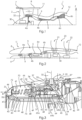
- Such turbomachines may be a turbojet as shown in the figure 1 or a turboprop as shown in the figure 2 .
- upstream and downstream are defined in relation to the circulation of gases in the turbomachine and here along the longitudinal axis X (and even from left to right on the figure 1 ).
- axial and “Axially” are also defined with respect to the longitudinal axis X.
- radial is defined with respect to a radial axis Z perpendicular to the longitudinal axis X and with respect to the distance from the longitudinal axis X.
- the turbomachine with longitudinal axis X, in axial and partial section is of the double-flow and double-body type and is intended to be mounted on an aircraft.
- This double-flow turbomachine 1 generally comprises a fan 2 mounted upstream of a gas generator 3.
- the gas generator 3 comprises, from upstream to downstream, a low pressure compressor 4a, a high pressure compressor 4b, a combustion chamber 5, a high pressure turbine 6a and a low pressure turbine 6b.
- the fan 2 which is surrounded by a fan casing 7, is said to be ducted.
- the fan casing is carried by a nacelle 8 surrounding the turbomachine.
- the fan divides the air entering the turbomachine into a primary air flow that passes through the gas generator 3 and in particular in a primary vein 9, and into a secondary air flow that circulates around the gas generator in a secondary vein 10.
- the secondary air flow is ejected by a secondary nozzle 11 terminating the nacelle while the primary air flow is ejected outside the turbomachine via an ejection nozzle 12 located downstream of the gas generator 3.
- turboprop-type turbomachine 1' comprises a pair of unducted propellers and is intended to be mounted on an aircraft.
- the identical or substantially identical elements described above are represented by the same numerical references.
- This turbomachine is known by the English expression “open rotor” or "unducted fan”. Turboprops are therefore distinguished from turbojets by the use of at least one propeller outside the nacelle (unducted) instead of an internal fan (ducted).
- the turbomachine 1' comprises a nacelle 8 or casing in which is arranged a gas generator 3 which comprises, from upstream to downstream, a low-pressure compressor 4a, a high-pressure compressor 4b, a combustion chamber 5, a high-pressure turbine 6a and a low-pressure turbine 6b.
- the gas generator may comprise a low-pressure compressor, a combustion chamber, a low-pressure turbine linked to the compressor and a free turbine.
- the propeller pair 20 comprises an upstream propeller 21 and a downstream propeller 22 which are here counter-rotating.
- the upstream 21 and downstream 22 propellers are mounted coaxially to the longitudinal axis X of the turbomachine and are arranged in radial parallel planes, which are perpendicular to the longitudinal axis X.
- the propellers 21, 22 are mounted downstream of the gas generator. A portion of the air flow entering the turbomachine passes through the gas generator in a primary vein 9 and is then ejected by the nozzle 12 to participate in the thrust of the turbomachine.
- the free turbine or turbines rotate the propellers 21, 22 which compress the air outside the nacelle and provide the majority of the thrust.
- the turboprop engine like the turbojet engine, comprises a turbomachine module with the blades of a propeller (upstream or downstream) and at least one pitch change system 30 of the blades.
- a turbomachine module with the blades of a propeller (upstream or downstream) and at least one pitch change system 30 of the blades.
- propeller is used to designate indifferently a fan or a propeller.
- the module comprises a rotating casing 31 about the longitudinal axis which carries the propeller 2 provided with a plurality of blades 32.
- Each blade 32 comprises a root 33 and extends radially outwards from the root. The free end of the blades is delimited radially by the fan casing 7 in the case of the turbojet.
- the rotating casing more precisely comprises a support ring 34 centered on the longitudinal axis X and which is provided with radial cylindrical housings 35 regularly distributed on the periphery of the support ring 34.
- the housings 35 each receive, in a pivoting manner along a setting axis A, a blade root 33.
- the setting axis A is parallel to the radial axis Z.
- each blade root is in the form of a pivot 36 which is mounted in a housing 35 by means of at least one guide bearing 37.
- two guide bearings 37, 37' are superimposed along the radial axis Z.
- These bearings 37 are plain bearings and each comprise an inner ring integral in rotation with the pivot and an outer ring which surrounds the inner ring. The outer ring is carried by the rotating casing 31.
- the rotating casing 31 comprises an inner wall 40 and an outer wall 41 which are of revolution.
- the inner wall and the outer wall form an annular volume 42.
- the outer wall 41 carries the support ring 34 of the blades.
- the inner wall 40 comprises upstream a first wall 43, of general shape substantially truncated cone-shaped, which is fixed to a first end 44 of generally truncated cone-shaped shape of the external wall 41.
- the second end 45 of the internal wall 40 is coupled to a second truncated cone-shaped wall 46 as well.
- the rotating casing 31 is supported by at least one bearing on a fixed casing 48 secured to a fixed structure of the turbomachine.
- the fixed casing 48 comprises a cylindrical wall 49 (here with a circular section) which extends radially between the inner wall 40 and the outer wall 41 of the rotating casing 31.
- the cylindrical wall 49 comprises at its upstream axial end 50, a first ferrule 51 of substantially frustoconical axial section and centered on the axis X.
- the first ferrule 51 is attached and fixed to the upstream axial end 50 of the cylindrical wall 49.
- the cylindrical wall 49 also comprises at its opposite axial end 52, downstream, a second shell 53 of substantially frustoconical axial section, centered on the axis X and fixed to the fixed structure of the turbomachine.
- the first shell 51 widens or flares from downstream to upstream relative to the longitudinal axis X while the second shell 53 widens or flares from downstream to upstream.
- a rolling bearing 47 is interposed upstream between the first shell 51 of the fixed casing 48 and the first wall 43 of the internal wall 40 of the rotating casing 31.
- the blade pitch change system 30 makes it possible to vary the pitch or the pitch of the blades around their pitch axes so that they occupy different angular positions depending on the operating conditions of the turbomachine and the flight phases concerned.
- Each blade pivots between an extreme working position (thrust reversal position known in English as "reverse") and an extreme blade feathering position.
- reverse extreme working position
- the propeller blades participate in braking the aircraft, in the manner of conventional thrust reversers and each have a pitch angle of the order of 5° relative to the plane of rotation of the blades.
- the blades are then erased as much as possible relative to the direction of advance of the aircraft, for example in the event of a turbomachine failure, which makes it possible to limit the drag.
- the blade pitch angle is positive, and is generally of the order of 90° relative to the plane of rotation of the blades.
- the blades pivot between these two extreme positions and can occupy a low pitch position where the speed of the turbomachine is low (for example on the ground) and of large pitch where the speed of the turbomachine is high (for example during climb and take-off).
- the pitch angle of small pitch is of the order of 30° relative to the plane of rotation of the blades while the pitch angle of large pitch is of the order of 40° for the take-off phases or of the order of 60° for the climb phases.
- the pitch change system 30 is arranged in the volume 42 formed by the inner wall 40 and the outer wall 41 of the rotating casing 31.
- the pitch change system 30 comprises a connecting mechanism 54 connected to the blades, a control means 55 acting on the connecting mechanism 54 and a load transfer bearing 56 kinematically arranged between the connecting mechanism 54 and the control means 55.
- the control means 55 comprises a movable body 57 axially on the fixed casing 48.
- the control means 55 comprises a fixed body 58 which is integral with the fixed structure of the turbomachine and the movable body 57 which moves in translation axially relative to the fixed body 58.
- the latter is mounted on the fixed casing so as to be immobile in translation and in rotation relative to the fixed casing 48.
- the fixed body 58 comprises an annular wall 59 which is coaxial with the longitudinal axis and which comprises a first free end 60 and a second end 61 opposite the first free end along the longitudinal axis. This second end 61 is fixed to the cylindrical wall 49 of the fixed casing towards its downstream end 52.
- the fixed body 58 comprises a radial wall 62 extending from the annular wall 59, outwards so as to delimit two chambers 63a, 63b with variable volumes and axially opposed in the movable body.
- the movable body is mounted around the cylindrical wall 49 of the fixed casing (and also extends radially outside the annular wall 59 of the fixed body 58).
- control means 55 is a hydraulic cylinder comprising the fixed body and the movable body.
- the control means 55 is connected to a fluid supply source for supplying pressurized oil to the chambers 63a, 63b of the movable body.
- the connecting mechanism 54 is connected on the one hand to the blades and on the other hand to the control means 55 via the load transfer bearing 56.
- the connecting mechanism 54 comprises several connecting rods 64 which each have a first end 64a connected to a blade and a second end 64b connected to the load transfer bearing 56.
- the load transfer bearing 56 is arranged between the connecting mechanism 54 and the movable body 57 of the control means 55 so as to ensure the transmission of the axial forces exerted by the movable body.
- the load transfer bearing comprises an inner ring 65 and an outer ring 66 forming raceways for rolling elements.
- the bearing 56 is formed by a two-row ball bearing.
- the inner ring 65 is mounted on an annular inner ferrule 67 around the longitudinal axis X and is connected to the movable body via a ring 68 coaxial with the axis X.
- the ring 68 comprises a wall which extends radially.
- the outer ring 66 is secured to an annular outer ferrule 69 which is connected to the connecting mechanism 54.
- the turbomachine module further comprises a device for feathering the blades 70 of the propeller.
- This device 70 comprises an annular row of springs 71 arranged around said fixed casing.
- the springs are regularly spaced around the longitudinal axis. Their number is between 6 and 20.
- Each spring 71 extends axially between a first axial end 72 and a second axial end 73.
- each spring is mounted radially between at least partly the annular wall of the fixed casing 48 and the external wall 41 of the rotating casing 31.
- Each spring also extends axially between a wall of the fixed casing 48 and the load transfer bearing 56.
- the first axial ends 72 of the springs bear on the first ferrule 51 of the fixed casing and the second axial ends 73 of the springs bear on the internal ring 65 of the load transfer bearing 56.
- the springs 71 are compression springs.
- the first ferrule 51 comprises an annular row of lugs 74 extending substantially radially relative to the longitudinal axis.
- the lugs are regularly distributed around the longitudinal axis.
- Each lug defines a housing 78 for receiving the first spring end.
- each ear comprises a radial base 75 and first partition 76 which extends axially from the radial base 75.
- the first partition 76 is semi-cylindrical with axis B (cf. figure 3 ).
- Each ear 74 also includes a second partition 77 that extends from the radial base 75, inside the first partition and coaxially.
- the second partition 77 is also semi-cylindrical.
- the first partition and the second partition are radially superimposed.
- the second partition 77 has an axial length l2 which is greater here than the axial length l1 of the first partition 76.
- the second partition is also spaced radially from the first partition and form between them the receiving housing 78 of a first spring end.
- the ring 68 fixed to the inner ring 65 of the load transfer bearing is coaxial with the longitudinal axis X.
- the second ends of the springs advantageously bear on this ring 68.
- the latter comprises receiving barrels 79 for the second ends.
- the receiving barrels 79 are arranged in an annular row around the longitudinal axis and are regularly distributed.
- Each receiving barrel comprises a bottom wall 80 and a wall 81 which extends axially from the bottom wall.
- the wall 81 is advantageously, but not limited to, semi-cylindrical with axis C (cf. figure 3 ).
- a part of each spring 71, in particular its second end 73, is housed inside the receiving barrel 79.
- Each receiving barrel 79 is arranged opposite an ear 74 axially as we can see in the figure 5 .
- the diameter of each wall of the receiving barrel is substantially equal to the diameter D1 of the first partition of the ears.
- Each receiving barrel 79 guides a spring 71 on the outer periphery thereof while the ear 74 (with its partitions 76, 77) guides the spring from the inside (inner periphery of the spring 71). This limits a minimum portion of the length of the spring which is left “free” and which deforms under the effect of centrifugal force, when the spring is relaxed.
- the springs 71 have their axes E located on a circumference whose diameter is substantially similar to the diameter of the inner ring of the load transfer bearing.
- the circumference corresponds substantially to the inner diameter of the inner ring of the load transfer bearing.
- the springs 71 have an axial dimension l3 greater than that (l4) of the load transfer bearing.
- the axial dimension of the springs 71 is also greater than the axial length l5 of the two chambers 63a, 63b of the movable body.
- the springs are also configured to have a relaxation or compression stroke capable of ensuring the movement of each blade from an extreme working position to an extreme flag position.
- FIGS. 6 and 7 are shown respectively the extreme working and feathering positions of the propeller blades.
- the movable body of the control means 55 In the extreme working position ( figure 7 ), the movable body of the control means 55 is located upstream of the annular volume 42.
- the springs 71 are compressed and are trapped in the closed cartridge 83 formed by each receiving barrel 79 and ear 74.
- the wall of the cylindrical barrel comprises an edge 82 which abuts against the radial internal wall of the base 75 of the corresponding ear.
- the movable body of the control means 55 is located downstream.
- Each spring 71 is stretched or relaxed between the ear and the corresponding receiving barrel.
- the edge 82 of the wall 81 of the receiving barrel is axially at a distance from the base 75 of the corresponding ear.
Landscapes
- Engineering & Computer Science (AREA)
- Mechanical Engineering (AREA)
- General Engineering & Computer Science (AREA)
- Aviation & Aerospace Engineering (AREA)
- Structures Of Non-Positive Displacement Pumps (AREA)
Claims (14)
- Modul einer Turbomaschine mit Längsachse X, wobei das Modul Folgendes umfasst:- ein um die Längsachse herum drehbares Gehäuse (31), das einen Propeller (2; 20, 21, 22) trägt, der mit einer Vielzahl von Blättern (32) ausgestattet ist;- ein festes Gehäuse (48), das eine zylindrische Wand (49) umfasst, die sich zwischen einer Innenwand (40) und einer Außenwand (41) des drehbaren Gehäuses (31) erstreckt; und- ein System (30) zur Änderung von Anstellwinkeln der Propellerblätter, das um das feste Gehäuse (48) herum montiert ist und Folgendes umfasst:wobei das Modul weiter eine Vorrichtung zur Segelstellungssetzung (70) der Propellerblätter umfasst, wobei das Modul dadurch gekennzeichnet ist, dass diese Vorrichtung (70) eine ringförmige Reihe von Federn (71) umfasst, die um das feste Gehäuse (48) herum angeordnet sind und sich axial erstrecken, wobei die Federn (71) regelmäßig um die Längsachse X herum beabstandet sind und erste axiale Enden (72), die auf einem Mantelring (51) des festen Gehäuses (48) aufliegen, und gegenüberliegende zweite axiale Enden (73), die auf dem inneren Ring (65) aufliegen, umfassen.- ein Steuermittel (55), das einen axial auf dem festen Gehäuse (48) beweglichen Körper (57) umfasst,- mindestens ein Lager zur Lastübertragung (56), umfassend einen inneren Ring (65), der mit dem beweglichen Körper (57) verbunden ist, und einen äußeren Ring (66); und- einen Verbindungsmechanismus (61) des äußeren Rings (66) mit den Propellerblättern,
- Modul nach dem vorstehenden Anspruch, dadurch gekennzeichnet, dass die Federn (71) Druckfedern sind.
- Modul nach dem Anspruch 1 oder 2, dadurch gekennzeichnet, dass die Anzahl der Federn (71) zwischen 6 und 20 beträgt.
- Modul nach einem der vorstehenden Ansprüche, dadurch gekennzeichnet, dass der Mantelring (51) an einem axialen Ende (50) einer zylindrischen Wand (49) des festen Gehäuses (48) angebracht und befestigt ist, wobei das Steuermittel (55) seinen beweglichen Körper (57) um diese zylindrische Wand (49) herum montiert aufweist.
- Modul nach einem der vorstehenden Ansprüche, dadurch gekennzeichnet, dass der bewegliche Körper (57) des Steuermittels (55) radial an der Außenseite einer ringförmigen Wand (59) eines festen Körpers (58) des Steuermittels (55) montiert ist.
- Modul nach einem der vorstehenden Ansprüche, dadurch gekennzeichnet, dass jede Feder (71) in einer Kassette (83) aufgenommen ist, die so konfiguriert ist, dass sie die Feder (71) auf ihrem Innenumfang und auf ihrem Außenumfang leitet.
- Modul nach einem der vorstehenden Ansprüche, dadurch gekennzeichnet, dass der Mantelring (51) eine ringförmige Reihe von Ohren (74) umfasst, die sich in Bezug auf die Längsachse im Wesentlichen radial erstrecken, wobei jedes Ohr (74) einen Sitz zur Aufnahme (78) eines ersten Endes (72) einer Feder definiert.
- Modul nach einem der vorstehenden Ansprüche, dadurch gekennzeichnet, dass die zweiten Enden (73) auf einem an dem inneren Ring (65) befestigten Begrenzungsring (68) aufliegen.
- Modul nach einem der vorstehenden Ansprüche, dadurch gekennzeichnet, dass der Begrenzungsring (68) Aufnahmeschafte (79) der zweiten Enden der Federn umfasst.
- Modul nach einem der Ansprüche 6 bis 9, dadurch gekennzeichnet, dass jede Kassette (83) aus einem Ohr (71) und einem Aufnahmeschaft (79) gebildet ist.
- Modul nach einem der Ansprüche 8 bis 10, dadurch gekennzeichnet, dass der innere Ring (65) des Lagers zur Lastübertragung (56) auf einem inneren Mantelring (67) montiert ist, der um die Längsachse X herum ringförmig ist, und über den zur Längsachse X koaxialen Begrenzungsring (68) mit dem beweglichen Körper (57) verbunden ist.
- Modul nach einem der vorstehenden Ansprüche, dadurch gekennzeichnet, dass die Achsen der Federn (71) auf einem Umfang gelegen sind, dessen Durchmesser ähnlich dem Durchmesser des inneren Rings (65) ist.
- Modul nach einem der vorstehenden Ansprüche, dadurch gekennzeichnet, dass die Federn (71) eine axiale Abmessung aufweisen, die größer ist als jene des mindestens einen Lagers zur Lastübertragung (56), und konfiguriert sind, um eine Entspannungs- oder Kompressionsbahn aufzuweisen, die geeignet ist, die Verschiebung jedes Blatts von einer extremen Arbeitsposition zu einer extremen Segelstellungsposition zu gewährleisten.
- Turbotriebwerk (1, 1') eines Luftfahrzeugs, umfassend mindestens ein Modul nach einem der vorstehenden Ansprüche.
Applications Claiming Priority (2)
| Application Number | Priority Date | Filing Date | Title |
|---|---|---|---|
| FR1908149A FR3098850B1 (fr) | 2019-07-18 | 2019-07-18 | Module de turbomachine equipe de systeme de changement de pas des pales d’une helice et d’un dispositif de mise en drapeau des pales. |
| PCT/FR2020/051291 WO2021009468A1 (fr) | 2019-07-18 | 2020-07-16 | Module de turbomachine équipé de système de changement de pas des pales d'une hélice et d'un dispositif de mise en drapeau des pales |
Publications (2)
| Publication Number | Publication Date |
|---|---|
| EP3999719A1 EP3999719A1 (de) | 2022-05-25 |
| EP3999719B1 true EP3999719B1 (de) | 2024-08-28 |
Family
ID=67999953
Family Applications (1)
| Application Number | Title | Priority Date | Filing Date |
|---|---|---|---|
| EP20753990.9A Active EP3999719B1 (de) | 2019-07-18 | 2020-07-16 | Komponent einer turbomaschine mit einer vorrichtung zur änderung des drehwinkels eines blattes und vorrichtung zum ausflaggen des blattes |
Country Status (5)
| Country | Link |
|---|---|
| US (1) | US11753143B2 (de) |
| EP (1) | EP3999719B1 (de) |
| CN (1) | CN114127388B (de) |
| FR (1) | FR3098850B1 (de) |
| WO (1) | WO2021009468A1 (de) |
Families Citing this family (1)
| Publication number | Priority date | Publication date | Assignee | Title |
|---|---|---|---|---|
| CN116357407B (zh) * | 2023-05-31 | 2023-08-18 | 日照职业技术学院 | 一种汽轮机用离心式定速装置 |
Family Cites Families (19)
| Publication number | Priority date | Publication date | Assignee | Title |
|---|---|---|---|---|
| GB559756A (en) * | 1942-08-31 | 1944-03-03 | Llewellyn Lloyd Davies | Improvements in or relating to variable-pitch propellers |
| GB773065A (en) * | 1955-11-14 | 1957-04-17 | Hartzell Industries | Improvements in or relating to propellers for aircraft |
| GB876954A (en) * | 1960-05-16 | 1961-09-06 | Hartzell Industries | Constant speed and feathering propeller |
| US5213471A (en) * | 1990-09-04 | 1993-05-25 | General Electric Company | Propeller pitch control |
| FR2911930A1 (fr) * | 2007-01-26 | 2008-08-01 | Snecma Sa | Turbopropulseur a helice a pas reglable |
| US7845910B2 (en) * | 2007-06-05 | 2010-12-07 | Hamilton Sundstrand Corporation | Propeller blade retention system with tapered roller bearing cartridge assemblies |
| US8573937B2 (en) * | 2008-11-21 | 2013-11-05 | Xzeres Corp. | System for providing dynamic pitch control in a wind turbine |
| FR2957986B1 (fr) * | 2010-03-29 | 2012-04-20 | Snecma | Dispositif de mise en drapeau des pales de souffante d'un turbopropulseur |
| US20130336796A1 (en) * | 2012-06-15 | 2013-12-19 | Hamilton Sundstrand Corporation | Modified taper roller edge |
| ITMO20130065A1 (it) * | 2013-03-13 | 2014-09-13 | Cnh Italia Spa | Ventilatore a passo variabile e metodo per variare il passo delle pale in un ventilatore. |
| US10072510B2 (en) * | 2014-11-21 | 2018-09-11 | General Electric Company | Variable pitch fan for gas turbine engine and method of assembling the same |
| FR3046432B1 (fr) * | 2016-01-05 | 2018-01-26 | Safran Aircraft Engines | Module de soufflante a aubes a calage variable pour une turbomachine |
| FR3046409B1 (fr) * | 2016-01-05 | 2018-02-09 | Safran Aircraft Engines | Systeme de commande de l'orientation des pales de soufflante d'une turbomachine a pion de blocage de mise en drapeau |
| FR3055000B1 (fr) * | 2016-08-10 | 2022-04-01 | Safran Aircraft Engines | Module de changement de pas pour turbomachine et turbomachine correspondante |
| US10415405B2 (en) * | 2017-04-21 | 2019-09-17 | United Technologies Corporation | Variable pitch fan blade system |
| FR3066558B1 (fr) * | 2017-05-18 | 2019-07-19 | Safran Aircraft Engines | Module de soufflante a pales a calage variable |
| EP3434585B1 (de) * | 2017-07-28 | 2021-04-14 | General Electric Company | Propellersteuerungssystem für ein flugzeug |
| CN108045560A (zh) * | 2017-12-04 | 2018-05-18 | 惠阳航空螺旋桨有限责任公司 | 一种用于螺旋桨定距锁结构 |
| FR3098789B1 (fr) * | 2019-07-15 | 2024-02-09 | Safran Aircraft Engines | Module de turbomachine pour une hélice à calage variable des pales et turbomachine le comportant |
-
2019
- 2019-07-18 FR FR1908149A patent/FR3098850B1/fr active Active
-
2020
- 2020-07-16 EP EP20753990.9A patent/EP3999719B1/de active Active
- 2020-07-16 WO PCT/FR2020/051291 patent/WO2021009468A1/fr not_active Ceased
- 2020-07-16 CN CN202080051168.9A patent/CN114127388B/zh active Active
- 2020-07-16 US US17/626,655 patent/US11753143B2/en active Active
Also Published As
| Publication number | Publication date |
|---|---|
| FR3098850A1 (fr) | 2021-01-22 |
| US20220289362A1 (en) | 2022-09-15 |
| WO2021009468A1 (fr) | 2021-01-21 |
| EP3999719A1 (de) | 2022-05-25 |
| CN114127388B (zh) | 2024-05-24 |
| CN114127388A (zh) | 2022-03-01 |
| FR3098850B1 (fr) | 2021-07-16 |
| US11753143B2 (en) | 2023-09-12 |
Similar Documents
| Publication | Publication Date | Title |
|---|---|---|
| EP4107398A1 (de) | Turbomaschinenmodul mit einem statorschaufelverstellsystem | |
| WO2023118686A1 (fr) | Module de turbomachine equipe d'aubes a calage variable et d'une virole annulaire d'interface | |
| EP4185767B1 (de) | Turbinenmotormodul mit propeller- und leitschaufeln mit haltevorrichtung und zugehöriger turbinenmotor | |
| EP4222355A1 (de) | Turbomaschinenmodul mit einem propeller und versetzten leitschaufeln | |
| EP3864297A1 (de) | Lüftermodul mit schaufeln mit variabler neigung | |
| EP3647546B1 (de) | Gebläsemodul mit schaufeln mit variablem einstellwinkel | |
| EP4073366B1 (de) | Aeronautisches antriebssystem mit niedriger leckrate und verbesserter antriebseffizienz | |
| EP3400170A1 (de) | System zur steuerung der richtung von gebläseschaufeln eines turbinenmotors mit segelstellungsverriegelungsstift | |
| EP4073371B1 (de) | Aeronautisches antriebssystem mit geringer leckflussrate und verbesserter antriebssystemseffizienz | |
| EP4380858B1 (de) | Turbine mit verstellbarem anstellwinkel | |
| EP3999719B1 (de) | Komponent einer turbomaschine mit einer vorrichtung zur änderung des drehwinkels eines blattes und vorrichtung zum ausflaggen des blattes | |
| WO2023247907A1 (fr) | Mécanisme de changement de pas avec dispositif de verrouillage de pas comprenant une vis à rouleaux satellites | |
| EP4408738B1 (de) | Modul für ein flugzeugturbinentriebwerk | |
| FR2992376A1 (fr) | Soufflante a calage variable par rotation differentielle des disques de soufflante | |
| EP4688558A1 (de) | Lüfterrad mit aktuator mit verriegelungseinrichtung | |
| FR3130746A1 (fr) | Module de soufflante a pales a calage variable | |
| FR3139551A1 (fr) | Module de soufflante a pales a calage variable | |
| WO2025088274A1 (fr) | Module de turbomachine equipe d'un systeme de changement de pas et d'un dispositif de transfert de fluide | |
| EP4608718A1 (de) | Neigungsänderungsmechanismus mit freitragender neigungsverriegelungsvorrichtung | |
| EP4658559A1 (de) | Neigungsänderungsmechanismus mit verriegelungsvorrichtung | |
| WO2024161087A1 (fr) | Mecanisme de changement de pas avec dispositif de verrouillage | |
| FR3137061A1 (fr) | Mécanisme de changement de pas avec dispositif de verrouillage de pas comprenant une vis à rouleaux satellites | |
| WO2022079378A1 (fr) | Système propulsif aéronautique ayant un rendement propulsif amélioré |
Legal Events
| Date | Code | Title | Description |
|---|---|---|---|
| STAA | Information on the status of an ep patent application or granted ep patent |
Free format text: STATUS: UNKNOWN |
|
| STAA | Information on the status of an ep patent application or granted ep patent |
Free format text: STATUS: THE INTERNATIONAL PUBLICATION HAS BEEN MADE |
|
| PUAI | Public reference made under article 153(3) epc to a published international application that has entered the european phase |
Free format text: ORIGINAL CODE: 0009012 |
|
| STAA | Information on the status of an ep patent application or granted ep patent |
Free format text: STATUS: REQUEST FOR EXAMINATION WAS MADE |
|
| 17P | Request for examination filed |
Effective date: 20220204 |
|
| AK | Designated contracting states |
Kind code of ref document: A1 Designated state(s): AL AT BE BG CH CY CZ DE DK EE ES FI FR GB GR HR HU IE IS IT LI LT LU LV MC MK MT NL NO PL PT RO RS SE SI SK SM TR |
|
| DAV | Request for validation of the european patent (deleted) | ||
| DAX | Request for extension of the european patent (deleted) | ||
| GRAP | Despatch of communication of intention to grant a patent |
Free format text: ORIGINAL CODE: EPIDOSNIGR1 |
|
| STAA | Information on the status of an ep patent application or granted ep patent |
Free format text: STATUS: GRANT OF PATENT IS INTENDED |
|
| INTG | Intention to grant announced |
Effective date: 20240207 |
|
| GRAS | Grant fee paid |
Free format text: ORIGINAL CODE: EPIDOSNIGR3 |
|
| GRAA | (expected) grant |
Free format text: ORIGINAL CODE: 0009210 |
|
| STAA | Information on the status of an ep patent application or granted ep patent |
Free format text: STATUS: THE PATENT HAS BEEN GRANTED |
|
| AK | Designated contracting states |
Kind code of ref document: B1 Designated state(s): AL AT BE BG CH CY CZ DE DK EE ES FI FR GB GR HR HU IE IS IT LI LT LU LV MC MK MT NL NO PL PT RO RS SE SI SK SM TR |
|
| REG | Reference to a national code |
Ref country code: CH Ref legal event code: EP |
|
| REG | Reference to a national code |
Ref country code: DE Ref legal event code: R096 Ref document number: 602020036687 Country of ref document: DE |
|
| REG | Reference to a national code |
Ref country code: IE Ref legal event code: FG4D Free format text: LANGUAGE OF EP DOCUMENT: FRENCH |
|
| REG | Reference to a national code |
Ref country code: LT Ref legal event code: MG9D |
|
| PG25 | Lapsed in a contracting state [announced via postgrant information from national office to epo] |
Ref country code: NO Free format text: LAPSE BECAUSE OF FAILURE TO SUBMIT A TRANSLATION OF THE DESCRIPTION OR TO PAY THE FEE WITHIN THE PRESCRIBED TIME-LIMIT Effective date: 20241128 |
|
| REG | Reference to a national code |
Ref country code: AT Ref legal event code: MK05 Ref document number: 1718129 Country of ref document: AT Kind code of ref document: T Effective date: 20240828 |
|
| PG25 | Lapsed in a contracting state [announced via postgrant information from national office to epo] |
Ref country code: NL Free format text: LAPSE BECAUSE OF FAILURE TO SUBMIT A TRANSLATION OF THE DESCRIPTION OR TO PAY THE FEE WITHIN THE PRESCRIBED TIME-LIMIT Effective date: 20240828 Ref country code: PL Free format text: LAPSE BECAUSE OF FAILURE TO SUBMIT A TRANSLATION OF THE DESCRIPTION OR TO PAY THE FEE WITHIN THE PRESCRIBED TIME-LIMIT Effective date: 20240828 Ref country code: GR Free format text: LAPSE BECAUSE OF FAILURE TO SUBMIT A TRANSLATION OF THE DESCRIPTION OR TO PAY THE FEE WITHIN THE PRESCRIBED TIME-LIMIT Effective date: 20241129 Ref country code: FI Free format text: LAPSE BECAUSE OF FAILURE TO SUBMIT A TRANSLATION OF THE DESCRIPTION OR TO PAY THE FEE WITHIN THE PRESCRIBED TIME-LIMIT Effective date: 20240828 Ref country code: PT Free format text: LAPSE BECAUSE OF FAILURE TO SUBMIT A TRANSLATION OF THE DESCRIPTION OR TO PAY THE FEE WITHIN THE PRESCRIBED TIME-LIMIT Effective date: 20241230 |
|
| PG25 | Lapsed in a contracting state [announced via postgrant information from national office to epo] |
Ref country code: BG Free format text: LAPSE BECAUSE OF FAILURE TO SUBMIT A TRANSLATION OF THE DESCRIPTION OR TO PAY THE FEE WITHIN THE PRESCRIBED TIME-LIMIT Effective date: 20240828 |
|
| PG25 | Lapsed in a contracting state [announced via postgrant information from national office to epo] |
Ref country code: LV Free format text: LAPSE BECAUSE OF FAILURE TO SUBMIT A TRANSLATION OF THE DESCRIPTION OR TO PAY THE FEE WITHIN THE PRESCRIBED TIME-LIMIT Effective date: 20240828 |
|
| REG | Reference to a national code |
Ref country code: NL Ref legal event code: MP Effective date: 20240828 |
|
| PG25 | Lapsed in a contracting state [announced via postgrant information from national office to epo] |
Ref country code: AT Free format text: LAPSE BECAUSE OF FAILURE TO SUBMIT A TRANSLATION OF THE DESCRIPTION OR TO PAY THE FEE WITHIN THE PRESCRIBED TIME-LIMIT Effective date: 20240828 Ref country code: IS Free format text: LAPSE BECAUSE OF FAILURE TO SUBMIT A TRANSLATION OF THE DESCRIPTION OR TO PAY THE FEE WITHIN THE PRESCRIBED TIME-LIMIT Effective date: 20241228 |
|
| PG25 | Lapsed in a contracting state [announced via postgrant information from national office to epo] |
Ref country code: HR Free format text: LAPSE BECAUSE OF FAILURE TO SUBMIT A TRANSLATION OF THE DESCRIPTION OR TO PAY THE FEE WITHIN THE PRESCRIBED TIME-LIMIT Effective date: 20240828 |
|
| PG25 | Lapsed in a contracting state [announced via postgrant information from national office to epo] |
Ref country code: RS Free format text: LAPSE BECAUSE OF FAILURE TO SUBMIT A TRANSLATION OF THE DESCRIPTION OR TO PAY THE FEE WITHIN THE PRESCRIBED TIME-LIMIT Effective date: 20241128 Ref country code: ES Free format text: LAPSE BECAUSE OF FAILURE TO SUBMIT A TRANSLATION OF THE DESCRIPTION OR TO PAY THE FEE WITHIN THE PRESCRIBED TIME-LIMIT Effective date: 20240828 |
|
| PG25 | Lapsed in a contracting state [announced via postgrant information from national office to epo] |
Ref country code: RS Free format text: LAPSE BECAUSE OF FAILURE TO SUBMIT A TRANSLATION OF THE DESCRIPTION OR TO PAY THE FEE WITHIN THE PRESCRIBED TIME-LIMIT Effective date: 20241128 Ref country code: PT Free format text: LAPSE BECAUSE OF FAILURE TO SUBMIT A TRANSLATION OF THE DESCRIPTION OR TO PAY THE FEE WITHIN THE PRESCRIBED TIME-LIMIT Effective date: 20241230 Ref country code: PL Free format text: LAPSE BECAUSE OF FAILURE TO SUBMIT A TRANSLATION OF THE DESCRIPTION OR TO PAY THE FEE WITHIN THE PRESCRIBED TIME-LIMIT Effective date: 20240828 Ref country code: NO Free format text: LAPSE BECAUSE OF FAILURE TO SUBMIT A TRANSLATION OF THE DESCRIPTION OR TO PAY THE FEE WITHIN THE PRESCRIBED TIME-LIMIT Effective date: 20241128 Ref country code: NL Free format text: LAPSE BECAUSE OF FAILURE TO SUBMIT A TRANSLATION OF THE DESCRIPTION OR TO PAY THE FEE WITHIN THE PRESCRIBED TIME-LIMIT Effective date: 20240828 Ref country code: LV Free format text: LAPSE BECAUSE OF FAILURE TO SUBMIT A TRANSLATION OF THE DESCRIPTION OR TO PAY THE FEE WITHIN THE PRESCRIBED TIME-LIMIT Effective date: 20240828 Ref country code: IS Free format text: LAPSE BECAUSE OF FAILURE TO SUBMIT A TRANSLATION OF THE DESCRIPTION OR TO PAY THE FEE WITHIN THE PRESCRIBED TIME-LIMIT Effective date: 20241228 Ref country code: HR Free format text: LAPSE BECAUSE OF FAILURE TO SUBMIT A TRANSLATION OF THE DESCRIPTION OR TO PAY THE FEE WITHIN THE PRESCRIBED TIME-LIMIT Effective date: 20240828 Ref country code: GR Free format text: LAPSE BECAUSE OF FAILURE TO SUBMIT A TRANSLATION OF THE DESCRIPTION OR TO PAY THE FEE WITHIN THE PRESCRIBED TIME-LIMIT Effective date: 20241129 Ref country code: FI Free format text: LAPSE BECAUSE OF FAILURE TO SUBMIT A TRANSLATION OF THE DESCRIPTION OR TO PAY THE FEE WITHIN THE PRESCRIBED TIME-LIMIT Effective date: 20240828 Ref country code: ES Free format text: LAPSE BECAUSE OF FAILURE TO SUBMIT A TRANSLATION OF THE DESCRIPTION OR TO PAY THE FEE WITHIN THE PRESCRIBED TIME-LIMIT Effective date: 20240828 Ref country code: BG Free format text: LAPSE BECAUSE OF FAILURE TO SUBMIT A TRANSLATION OF THE DESCRIPTION OR TO PAY THE FEE WITHIN THE PRESCRIBED TIME-LIMIT Effective date: 20240828 Ref country code: AT Free format text: LAPSE BECAUSE OF FAILURE TO SUBMIT A TRANSLATION OF THE DESCRIPTION OR TO PAY THE FEE WITHIN THE PRESCRIBED TIME-LIMIT Effective date: 20240828 |
|
| PG25 | Lapsed in a contracting state [announced via postgrant information from national office to epo] |
Ref country code: SM Free format text: LAPSE BECAUSE OF FAILURE TO SUBMIT A TRANSLATION OF THE DESCRIPTION OR TO PAY THE FEE WITHIN THE PRESCRIBED TIME-LIMIT Effective date: 20240828 Ref country code: RO Free format text: LAPSE BECAUSE OF FAILURE TO SUBMIT A TRANSLATION OF THE DESCRIPTION OR TO PAY THE FEE WITHIN THE PRESCRIBED TIME-LIMIT Effective date: 20240828 Ref country code: DK Free format text: LAPSE BECAUSE OF FAILURE TO SUBMIT A TRANSLATION OF THE DESCRIPTION OR TO PAY THE FEE WITHIN THE PRESCRIBED TIME-LIMIT Effective date: 20240828 |
|
| PG25 | Lapsed in a contracting state [announced via postgrant information from national office to epo] |
Ref country code: EE Free format text: LAPSE BECAUSE OF FAILURE TO SUBMIT A TRANSLATION OF THE DESCRIPTION OR TO PAY THE FEE WITHIN THE PRESCRIBED TIME-LIMIT Effective date: 20240828 |
|
| PG25 | Lapsed in a contracting state [announced via postgrant information from national office to epo] |
Ref country code: CZ Free format text: LAPSE BECAUSE OF FAILURE TO SUBMIT A TRANSLATION OF THE DESCRIPTION OR TO PAY THE FEE WITHIN THE PRESCRIBED TIME-LIMIT Effective date: 20240828 |
|
| PG25 | Lapsed in a contracting state [announced via postgrant information from national office to epo] |
Ref country code: IT Free format text: LAPSE BECAUSE OF FAILURE TO SUBMIT A TRANSLATION OF THE DESCRIPTION OR TO PAY THE FEE WITHIN THE PRESCRIBED TIME-LIMIT Effective date: 20240828 Ref country code: SK Free format text: LAPSE BECAUSE OF FAILURE TO SUBMIT A TRANSLATION OF THE DESCRIPTION OR TO PAY THE FEE WITHIN THE PRESCRIBED TIME-LIMIT Effective date: 20240828 |
|
| REG | Reference to a national code |
Ref country code: DE Ref legal event code: R097 Ref document number: 602020036687 Country of ref document: DE |
|
| PLBE | No opposition filed within time limit |
Free format text: ORIGINAL CODE: 0009261 |
|
| STAA | Information on the status of an ep patent application or granted ep patent |
Free format text: STATUS: NO OPPOSITION FILED WITHIN TIME LIMIT |
|
| 26N | No opposition filed |
Effective date: 20250530 |
|
| PG25 | Lapsed in a contracting state [announced via postgrant information from national office to epo] |
Ref country code: SE Free format text: LAPSE BECAUSE OF FAILURE TO SUBMIT A TRANSLATION OF THE DESCRIPTION OR TO PAY THE FEE WITHIN THE PRESCRIBED TIME-LIMIT Effective date: 20240828 |
|
| PGFP | Annual fee paid to national office [announced via postgrant information from national office to epo] |
Ref country code: DE Payment date: 20250722 Year of fee payment: 6 |
|
| PGFP | Annual fee paid to national office [announced via postgrant information from national office to epo] |
Ref country code: GB Payment date: 20250724 Year of fee payment: 6 |
|
| PGFP | Annual fee paid to national office [announced via postgrant information from national office to epo] |
Ref country code: FR Payment date: 20250722 Year of fee payment: 6 |
|
| REG | Reference to a national code |
Ref country code: CH Ref legal event code: H13 Free format text: ST27 STATUS EVENT CODE: U-0-0-H10-H13 (AS PROVIDED BY THE NATIONAL OFFICE) Effective date: 20260224 |
|
| PG25 | Lapsed in a contracting state [announced via postgrant information from national office to epo] |
Ref country code: LU Free format text: LAPSE BECAUSE OF NON-PAYMENT OF DUE FEES Effective date: 20250716 |
|
| REG | Reference to a national code |
Ref country code: BE Ref legal event code: MM Effective date: 20250731 |
|
| PG25 | Lapsed in a contracting state [announced via postgrant information from national office to epo] |
Ref country code: BE Free format text: LAPSE BECAUSE OF NON-PAYMENT OF DUE FEES Effective date: 20250731 |