EP4000183B1 - Pim-unterdrückung - Google Patents
Pim-unterdrückung Download PDFInfo
- Publication number
- EP4000183B1 EP4000183B1 EP19746377.1A EP19746377A EP4000183B1 EP 4000183 B1 EP4000183 B1 EP 4000183B1 EP 19746377 A EP19746377 A EP 19746377A EP 4000183 B1 EP4000183 B1 EP 4000183B1
- Authority
- EP
- European Patent Office
- Prior art keywords
- pim
- slope
- value
- reduced
- power
- Prior art date
- Legal status (The legal status is an assumption and is not a legal conclusion. Google has not performed a legal analysis and makes no representation as to the accuracy of the status listed.)
- Active
Links
Images


Classifications
-
- H—ELECTRICITY
- H04—ELECTRIC COMMUNICATION TECHNIQUE
- H04B—TRANSMISSION
- H04B1/00—Details of transmission systems, not covered by a single one of groups H04B3/00 - H04B13/00; Details of transmission systems not characterised by the medium used for transmission
- H04B1/06—Receivers
- H04B1/10—Means associated with receiver for limiting or suppressing noise or interference
- H04B1/109—Means associated with receiver for limiting or suppressing noise or interference by improving strong signal performance of the receiver when strong unwanted signals are present at the receiver input
-
- H—ELECTRICITY
- H04—ELECTRIC COMMUNICATION TECHNIQUE
- H04B—TRANSMISSION
- H04B1/00—Details of transmission systems, not covered by a single one of groups H04B3/00 - H04B13/00; Details of transmission systems not characterised by the medium used for transmission
- H04B1/06—Receivers
- H04B1/10—Means associated with receiver for limiting or suppressing noise or interference
- H04B1/12—Neutralising, balancing, or compensation arrangements
- H04B1/123—Neutralising, balancing, or compensation arrangements using adaptive balancing or compensation means
-
- H—ELECTRICITY
- H04—ELECTRIC COMMUNICATION TECHNIQUE
- H04B—TRANSMISSION
- H04B1/00—Details of transmission systems, not covered by a single one of groups H04B3/00 - H04B13/00; Details of transmission systems not characterised by the medium used for transmission
- H04B1/38—Transceivers, i.e. devices in which transmitter and receiver form a structural unit and in which at least one part is used for functions of transmitting and receiving
- H04B1/40—Circuits
- H04B1/50—Circuits using different frequencies for the two directions of communication
- H04B1/52—Hybrid arrangements, i.e. arrangements for transition from single-path two-direction transmission to single-direction transmission on each of two paths or vice versa
- H04B1/525—Hybrid arrangements, i.e. arrangements for transition from single-path two-direction transmission to single-direction transmission on each of two paths or vice versa with means for reducing leakage of transmitter signal into the receiver
Definitions
- This specification relates to an apparatus, method and computer program product relating to the cancellation, or mitigation, of Passive InterModulation (PIM).
- PIM Passive InterModulation
- PIM Passive InterModulation
- a non-linear system may be a system comprising active components, but non-linearity may also occur in passive components, usually at higher power than active components e.g. due to corroded connectors etc. If the non-linearity of passive components is severe, even low power may be sufficient to cause PIM. Due to PIM, intermodulation products occur at frequencies corresponding to k a f a + k b f b + k c f c + ..., wherein f a , f b , f c,...
- k a , k b , k c,... are integer coefficients (positive, negative, or 0).
- the sum k a +k b +k c + ,... is denoted as the order of the intermodulation product, denoted as IMP3, IMP5, IMP7 etc. for IMP of 3 rd , 5 th , and 7 th order, respectively (note that these sums may use the absolute values of the k coefficients, in the event that those coefficients may be negative).
- the amplitude of the IMPs decreases with increasing order of the IMPs.
- IMP3 is typically most relevant because it is located close to the input signal and has relatively high amplitude. If a broadband signal is transmitted through the non-linear system, PIM may cause the occurrence of side-lobes.
- PIM Planar metal-oxide-semiconductor
- IEC 62037 In this measurement, two tones each of 20 W are input into the non-linear system, the powers of the IMPs (e.g.
- IMP3, IMP5, and IMP7 higher order IMPs may be neglected
- PIM value the ratio of the power of IMP3 to the input power at carrier level
- the measure of PIM may arise from a PIM model estimated by a PIM cancellation (PIMC) algorithm.
- US 2017/00192679 A1 discloses an apparatus for detecting a correlation value between a replica signal for passive intermodulation distortion and a reception signal and suppressing the peak of a multicarrier signal when the correlation value meets a threshold.
- US 2012/0295558 A1 discloses a wireless communication node that dynamically estimates passive intermodulation interference and then cancels the estimated passive intermodulation interference.
- US 2017/0222858 A1 discloses mitigating passive intermodulation interference by reducing a degree of correlation between streams of time samples of a simulated passive intermodulation product.
- US 2018/0262370 A1 discloses diminishing passive intermodulation by estimating passive intermodulation distortion products by filtering time delayed upsampled signals.
- the apparatus is configured to perform the corresponding method, although in some cases only the apparatus or only the method are described.
- the operations of the method may be embodied in a computer program product on, for example, a non-transitory medium.
- Cellular base stations may de-sense their own uplink owing to PIM products, for example introduced by passive components such as duplexers, cables, connector interfaces, antennas etc. If PIM is not mitigated, e.g. reduced or cancelled, it may not be possible to decode received signals. Operators may use PIM cancellation algorithms to improve uplink signal quality.
- PIM Passive InterModulation
- a transmit signal that is 49dBm of power causes PIM levels that are -81dBm to -101dBm corresponding to -130 dBc to -150 dBc PIM source range.
- PIM signals can be higher than the receive signals.
- the receiver decoding process will fail due to negative signal to noise ratio. This may cause a significant throughput loss in the uplink direction (mobile to base station).
- Some radios or associated equipment are designed to mitigate, i.e. reduce or avoid, such PIM effects with PIM cancellation (PIMC) systems or algorithms.
- PIMC PIM cancellation
- the term cancellation may also mean mitigate.
- a PIMC algorithm uses a model that attempts to cancel, or at least reduce, the PIM products on the receiver (Rx) bandwidth.
- FIG. 1 is a schematic diagram of an example transceiver system 10 that involves PIM cancellation according to example embodiments.
- the transceiver system 10 comprises a duplexer 12 connected to a common antenna 14; the duplexer 12 comprises first and second duplexer filters, a first being a transmitter (Tx) duplexer filter having a passband providing a signal path between a transmitter (Tx) 16 and the antenna, and the second being a receiver (Rx) duplexer filter providing a signal path between the antenna and a receiver (Rx) 18. No path between the transmitter 16 and the receiver 18 should exist.
- Tx transmitter
- Rx receiver
- a PIMC module 20 may be provided between the input and output paths of the transmitter 16 and receiver 18 respectively.
- the PIMC module 20 may be implemented in hardware, software or a combination thereof.
- the PIMC module 20 operates using an algorithm which is similar to known PIMC algorithms and which uses a PIM model 22 to determine how to cancel the PIM.
- IEC-62037 describes a way to measure PIM using a so-called two-tone test.
- Example embodiments may also involve PIMC algorithms that may be enabled (turned ON) and disabled (turned OFF), which may be applied when the transceiver system 10 operates in a Frequency Division Duplex (FDD) mode.
- Example embodiments may be applied in any related or future telecoms technology, including for example, 3G, 4G, 5G etc.
- PIM effects may differ depending on factors such as, but not limited to, where the base station is positioned geographically, the environment it is in, the specific components used and their interconnections.
- PIMC techniques may allow the network operator to turn ON the PIMC algorithm when the radio equipment ages. For example, ageing connectors and bolts of the radio equipment may create intermodulation products that land on receive frequencies causing the receiver SNR to degrade. Thus, this may result in significant uplink throughput losses.
- PIMC algorithms may mitigate the problem by cancelling out interfering PIM products, the time to turn ON the algorithm is a separate, but equally important consideration.
- the PIMC turn ON decision may be based on the amount of PIM that is above the noise floor. For example, when PIM is detected tens of dB above the noise floor, the accuracy of the extracted PIM model is found to be high.
- the PIMC algorithm will substantially eliminate the interfering PIM, enabling the user to recover the loss in throughput.
- the extracted PIM model may not be that accurate.
- the cancellation may, on some occasions, cause more degradation than the interfering PIM signal itself. Therefore, on such occasions, it may be better to leave the PIM products in the uncorrected state to cause no further damage.
- the other concern for model extraction is the lack of static and stable downlink traffic during actual operation. Note that real traffic is non-contiguous. Hence, during the model extraction process, the PIMC algorithm may experience little traffic, thus exacerbating the problem of what the input noise would do to the model.
- the level of PIM signal in decibels relative to the carrier may be used to compare how close it is to the noise floor.
- a decision threshold may be set a certain number of dBs above the noise floor. If the estimated level of the PIM signal is closer to the noise floor, i.e. at or below the decision threshold, PIMC can be turned OFF. If above, PIMC can be turned ON.
- the level of the PIM signal can only be accurately determined or estimated when the "slope" of the PIM source presented to the system is obtained either empirically or theoretically, as explained later.
- a PIM slope 29 refers to the relationship between an input power (in dBm) and PIM signal power (also in dBm) that result from the input signal power.
- the PIM signal power is based on the IM3 component only, and different slopes 29 for each of three different PIM sources are shown.
- the PIM slope for a given component forms the basis of the model 22 used in PIMC algorithms and systems, e.g. in the PIMC module 20.
- PIM slope 29 of a PIM source is unknown, even if the model 22 is accurate (e.g. PIMC is ON because PIM signal is determined to be considerably higher than the noise floor) estimation and subsequent reporting of PIM level in dBc, per the IEC-62037 standard, requires “assuming” a "typical” slope of the PIM source based on typical PIM components characterized in a laboratory. Often, the PIM slope 29 of a PIM source in the field is totally different from a typical PIM slope. This may lead to inaccurate estimation and reporting of PIM levels due to mismatch error between the "actual" PIM slope of the PIM source in the field and the "typical" PIM slope of PIM sources characterized in the lab.
- example embodiments relate to characterizing the PIM slope, for example without disrupting the normal operation of the transmitter, for example using live traffic, of the presented PIM source in the field.
- Example embodiments herein provide a way of estimating the real-time slope 29 of a PIM source in the field, which may be presented to a system in the presence of real-time, live traffic. Further, example embodiments may use the estimated PIM slope 29 to determine whether or not to turn PIMC ON or OFF. Further, the estimated PIM slope 29 may be used to report the PIM level in dBc, as per the IEC-62047 standard, more accurately and in real-time or near real-time.
- example embodiments to be described below are based on third order PIM products, i.e. IM3. This is because most in-field configurations are exposed to IM3 PIM products and the PIM level is higher on such products.
- example embodiments are not limited to IM3 PIM products, and can be extended to fifth order (IM5) and seventh order (IM7) PIM products etc. if they are relatively higher than the receiver noise floor.
- the power of the third order PIM product IM3 is dependent on the power of transmit signals. Mathematics can also show that, for every 1dB drop of transmit power, the power of the third order PIM will drop by 3dB. Hence, with a 2dB of transmit power, the drop of the third order PIM power is expected to be 6dB. This is simply annotated by the theoretical 3dB per 1dB PIM slope. However, passive devices in nature do not follow the theoretical 3dB per 1dB slope. Instead, the typical PIM slopes for practical devices range between 2.2-2.8 dB per every one dB drop.
- a PIM slope is intimately related to PIMC ON/OFF decisions. Since an ON/OFF decision occurs when PIM level is closer to the noise floor, the PIMC algorithm cannot rely on the extracted PIM model alone to make a correct decision. PIM slope number will take a higher weight on the decision to turn ON/OFF the PIMC algorithm. The PIM slope also helps characterize the PIM level in dBc at a higher accuracy, which subsequently helps in ON/OFF decisions as well as reporting the "real-time" dBc value of the PIM source per IEC-62037.
- the OCNS fills-in unused resource blocks of LTE carriers.
- the power of the LTE carrier will be at a maximum during the OCNS transmission.
- Third order PIM products IM3 will be at their highest power during this time as well.
- a receiver e.g. an eNB / gNB / base station noise floor (N dBm per MHz) can be known by prior measurements.
- Peak PIM power location (frequency) is known from a transmit signal configuration. With an FFT based filter, the peak PIM power per MHz ( P dBm per MHz) can also be computed.
- P-N ) dBc will be the level of PIM at the highest point above the noise floor.
- the power towards the PIM load needs to be lowered by a known amount.
- the power reduction is denoted as P_diff.
- the OCNS fills-in all available LTE resource blocks. By removing a certain number of resources blocks, the power of the transmit signal can be reduced by P_diff.
- the peak PIM power per MHz P reduced can be computed as described later on.
- PIM slope P ⁇ P reduced / P diff
- a second example embodiment method will now be described. While the first method may require a specific alternation for OCNS, a statistical method may also yield the same answer.
- the statistical method can be applied with real traffic and so not requiring an OCNS for PIM power measurement.
- RF software may be used to measure the statistical power of the transmit signals within a time period from t1 to t2. Baseband transmit signal power measured during this time period is compared with when OCNS is ON. The difference will be equivalent to P_diffnew as in the first method. During the same time (i.e. t1 to t2 ), the RF software will make a statistical measurement of the PIM at its peak ( P reduced_ne ⁇ ).
- PIM slope P ⁇ P reduced _ new / P diffnew
- the frequency location of the PIM peak may move slightly within the F MHz measurement window.
- the window will be sufficiently wide, and will capture the power of the PIM during the allotted time.
- the PIM power can be normalized to a per MHz basis.
- the level of the PIM signal can be predicted with equation [3].
- RF software can corroborate the predicted answer by performing a statistical measure of Peak PIM power per MHz via FFT filtering, at the same time as when the transmit power was measured.
- Other example embodiments may involve reporting the PIM level per the IEC-62037 standard with an accurate model.
- the OCNS fills-in all available LTE resource blocks.
- the power of the transmit signal can be reduced by P _ diff.
- the "model" to cancel PIM at full power i.e., all available resource blocks
- the dBc level of PIM signal from the model estimate at full power (denote it as P dBC ) and reduced power (denote it as P reduced_dBc ) can be found.
- a second example embodiment method will now be described. While the first method may require a specific alternation for OCNS, a statistical method may also yield the same answer.
- the statistical method can be applied with real traffic and thus does not requiring OCNS for PIM power measurement.
- the transmit power may be monitored using power meters. Power meters are available on a per carrier basis.
- RF software may measure the statistical power of the transmit signals within a time period from t1 to t2. Baseband transmit signal power measured during this time period is compared with when OCNS is ON. The difference will be equivalent to P_diffnew_dBc. During the same time (i.e.
- the frequency location of the PIM peak may move slightly within the F MHz measurement window.
- the window is sufficiently wide, and may capture the power of the PIM during the allotted time.
- the PIM power can be normalized to a per MHz basis.
- IM3 PIM model is applicable for the vast majority of the PIM configurations, the following mathematical model is derived considering IM3 PIM power in mind. For simplicity, it is assumed that only IM3 is deemed to follow the PIM slope.
- Pim _ OCNS filt c 1 ⁇ x n ⁇ x n 2 + c 2 ⁇ x n ⁇ 1 ⁇ x n ⁇ 1 2 + c 3 ⁇ x n + 1 ⁇ x n + 1 2 + c 4 ⁇ x n ⁇ x n 4 + c 5 ⁇ x n ⁇ 1 ⁇ x n ⁇ 1 4 + c 6 ⁇ x n + 1 ⁇ x n + 1 4
- Coefficients C1, C2, C3, ...C6 are extracted using the standard least squares method, using conventional techniques.
- the function filt filters the PIM signal to a known bandwidth (i.e. F MHz).
- the function filt can either be a time domain mechanism or a frequency domain (i.e. FFT based) mechanism.
- the term x(n) is the transmit signal. Bandwidth of filt is selected to capture only IM3 PIM components of the PIM signal.
- the power of the transmit signal can be computed or measured using power meters.
- Equation [9] unaltered, will not follow the PIM slope inherent with the two measurements described in a) and b). Some modifications will be required to make it compliant with equation [10].
- the concerned PIM power difference ( Pim ⁇ power ) is primarily based on IM3 PIM products only.
- the extra fifth order terms, shown in equation [9], can then be used to rectify the non-compliant problem with the PIM slope.
- the fifth order terms also contribute energy towards the IM3 PIM products. Hence by manipulating the fifth order terms, it is possible to match any PIM slope that appears in nature.
- equations [11] and [12] consist of an extra rotation coefficient r that multiplies 5 th order coefficients c4 , c5 , and c6 .
- r By rotating the 5 th order, its contribution towards IM3 can be used appropriately to match the PIM slope.
- r can be used to match any natural PIM slope in the range of 2.2-2.8 dB per dB power change.
- the values of ⁇ and ⁇ can be determined iteratively through software.
- equations [11] and [12] are altered to match only the power differences of Pim_OCNS_matched and Pim_xr_matched to (P - P reduced new ).
- Pim_OCNS_matched power and Pim_xr_matched power do not have to be equal to P or P reduced_new . Since P is known, the difference in power is sufficient to predict the PIM power that is compliant with the PIM slope.
- FIG. 3 is a flow diagram illustrating operations according to an example embodiment that may be performed by an RF system, for example a control system in, or associated with, a base station.
- an RF system for example a control system in, or associated with, a base station.
- a first operation S31 may comprise determining a PIM slope using any above method.
- a second operation S32 may comprise deriving a PIM value based on the PIM slope.
- a third operation S33 may comprise reporting the PIM value, for example as per the IEC-62037 standard.
- FIG. 4 is a flow diagram illustrating operations according to another example embodiment that may be performed by an RF system, for example a control system in, or associated with, a base station.
- an RF system for example a control system in, or associated with, a base station.
- a first operation S41 may comprise determining a PIM slope using any above method.
- a second operation S42 may comprise deriving a PIM value based on the PIM slope.
- a third operation S43 may comprise controlling PIMC accordingly.
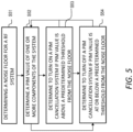
- FIG. 5 is a flow diagram illustrating operations according to another example embodiment that may be performed by an RF system, for example a control system in, or associated with, a base station.
- an RF system for example a control system in, or associated with, a base station.
- a first operation S51 may comprise determining a noise floor for the RF system.
- a second operation S52 may comprise determining a PIM value of a source component of the RF system.
- a third operation S53 may comprise determining to turn on a PIM cancellation system if the PIM value is above a predetermined threshold from the noise floor.
- the predetermined threshold may be a configurable parameter.
- a fourth operation S54 may comprise determining to turn off a PIM cancellation system if the PIM value is at or below the predetermined threshold from the noise floor.
- one of the two operations S33, S34 may be entered from the second operation S32, depending on the current state.
- the term “turn” may be replaced with “maintain” with no change to the intended scope of the term if the current on/off state is to remain the same.
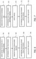
- FIGS. 6 and 7 are flow diagrams illustrating operations according to other example embodiments that may be performed by an RF system, for example a control system in, or associated with, a base station. More specifically, FIGS. 6 and 7 relate to calculating the PIM slope using the experimental approach outlined above using noise, for example using OCNS.
- a first operation S61 may comprise applying noise to blocks of a carrier signal.
- a second operation S62 may comprise determining peak PIM power.
- a third operation S63 may comprise removing noise from some of the blocks.
- a fourth operation S64 may comprise determining reduced noise peak PIM power.
- a fifth operation S65 may comprise calculating the PIM slope.
- a first operation S71 in this case may comprise measuring the power in normal use.
- a second operation S72 may comprise determining peak PIM power, without noise.
- a third operation S73 may comprise applying noise.
- a fourth operation S74 may comprise determining peak PIM power, with the applied noise.
- a fifth operation S75 may comprise calculating the PIM slipe.
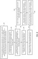
- FIG. 8 is a flow diagram illustrating operations according to another example embodiment that may be performed by an RF system, for example a control system in, or associated with, a base station. More specifically, the flow diagram relates to the above-mentioned theoretical approach.
- a first operation S81 may comprise measuring transmit power with full noise, e.g. OCNS, on, and determining the value to be P_OCNS.
- the first operation S82, or another operation may also comprise measuring the transmit power with partial noise, and determining the value to be P_reduced.
- the first operation S82, or another operation may also comprise measuring the PIM level with full noise and partial noise and determining the values to be PIM_OCNS_measured and PIM_Reduced_measured respectively.
- a second operation S82 may comprise estimating the PIM with noise on for all blacks (with full noise on) with 3 rd and 5 th order terms. This value may be determined as PIM_OCNS.
- a third operation S83 may comprise estimating the PIM with noise on for some blocks (partial noise on) with 3 rd and 5 th order terms. This value may be determined as PIM_Reduced.
- a fourth operation S84 may comprise rotating the 5 th order terms used in PIM_OCNS with a complex rotation 'r.' This value may be determined as PIM_OCNS_matched.
- a fifth operation S85 may comprise rotating the 5 th order terms used in PIM_Reduced with a complex rotation 'r.'
- a sixth operation S86 may comprise determining the PIM_slope_measured to be: PIM OCNS measured ⁇ PIM Reduced measured _ P_OCNS ⁇ P_Reduced .
- a seventh operation S87 may comprise determining the PIM_slope_actual to be: PIM OCNS matched ⁇ PIM Reduced measured _ P_OCNS ⁇ P_Reduced .
- An eighth operation S88 may comprise finding the rotation 'r' until PIM_slope_actual matches PIM_slope_measured.
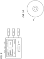
- FIG. 9 shows an apparatus according to an embodiment.
- the apparatus may be configured to perform the operations described herein, for example operations described with reference to any one or more of FIGS. 3 - 8 .
- the apparatus comprises at least one processor 420 and at least one memory 410 directly or closely connected to the processor.
- the memory 410 includes at least one random access memory (RAM) 410b and at least one read-only memory (ROM) 410a.
- Computer program code (software) 415 is stored in the ROM 410a.
- the apparatus may be connected to a TX path and a RX path of a base station in order to obtain respective signals. However, in some embodiments, the TX signals and RX signals are input as data streams into the apparatus.
- the apparatus may be connected with a user interface UI for instructing the apparatus and/or for outputting results.
- the instructions may be input e.g. from a batch file, and the output may be stored in a non-volatile memory.
- the at least one processor 420, with the at least one memory 410 and the computer program code 415 are arranged to cause the apparatus to at least perform at least the method according to FIG. 3 .
- FIG. 10 shows a non-transitory media 430 according to some embodiments.
- the non-transitory media 430 is a computer readable storage medium. It may be e.g. a CD, a DVD, a USB stick, a blue ray disk, etc.
- the non-transitory media 430 stores computer program code causing an apparatus to perform the method of FIG. 3 .
- a base station may be a BTS, a NodeB, an eNodeB, a WiFi access point etc.
- a memory may be volatile or non-volatile. It may be e.g. a RAM, an SRAM, a flash memory, an FPGA block ram, a DCD, a CD, a USB stick, and a blue ray disk. If not otherwise stated or otherwise made clear from the context, the statement that two entities are different means that they perform different functions. It does not necessarily mean that they are based on different hardware. That is, each of the entities described in the present description may be based on a different hardware, or some or all of the entities may be based on the same hardware. It does not necessarily mean that they are based on different software. That is, each of the entities described in the present description may be based on different software, or some or all of the entities may be based on the same software. Each of the entities described in the present description may be embodied in the cloud.
- example embodiments provide, for example, a PIM slope estimator, a PIMC algorithm module or controller therefore, or a component thereof, an apparatus embodying the same, a method for controlling and/or operating the same, and computer program(s) controlling and/or operating the same as well as mediums carrying such computer program(s) and forming computer program product(s).
- Implementations of any of the above described blocks, apparatuses, systems, techniques or methods include, as non-limiting examples, implementations as hardware, software, firmware, special purpose circuits or logic, general purpose hardware or controller or other computing devices, or some combination thereof. Some embodiments may be implemented in the cloud.
- Model is our basis function X.
Landscapes
- Engineering & Computer Science (AREA)
- Computer Networks & Wireless Communication (AREA)
- Signal Processing (AREA)
- Mobile Radio Communication Systems (AREA)
- Transmitters (AREA)
Claims (15)
- Verfahren, das Folgendes umfasst:Bestimmen eines Rauschbodens für ein Funkfrequenz(RF)-System;Bestimmen eines passiven Intermodulations(PIM)-Wertes einer Komponente des RF-Systems, die als eine Quelle von PIM beiträgt, wobei das Bestimmen des PIM-Wertes durch Bestimmen eines PIM-Gefälles (29) für die eine oder die mehreren Komponenten in Echtzeit oder nahezu Echtzeit, wobei das PIM-Gefälle (29) eine Dezibeländerung der PIM-Leistung pro Dezibel Änderung einer angelegten Trägersignalleistung repräsentiert, und Anlegen einer aktuellen Signalleistung an das bestimmte PIM-Gefälle (29) durchgeführt wird, und wobei das PIM-Gefälle (29) durch Subtrahieren eines PIM-Spitzenwertes infolge einer reduzierten angelegten Signalleistung vom PIM-Spitzenwert bei einer angelegten Trägersignalleistung und Dividieren eines Ergebnisses durch eine Menge, um die die angelegte Trägersignalleistung reduziert wird, bestimmt wird;Bestimmen, dass ein passives Intermodulations(PIM)-Unterdrückungssystem aktiviert werden sollte, wenn der PIM-Wert vom Rauschboden über einem vorbestimmten Schwellwert liegt; undBestimmen, dass das PIM-Unterdrückungssystem deaktiviert werden sollte, wenn der PIM-Wert beim oder über dem vorbestimmten Schwellwert liegt.
- Verfahren nach Anspruch 1, wobei das PIM-Gefälle durch Verwenden von Folgendem bestimmt wird:

- Verfahren nach Anspruch 2, wobei der PIM-Wert P durch Anlegen eines künstlichen Rauschens an verfügbare Ressourcenblöcke eines angelegten Trägersignals, Bestimmen des PIM-Spitzenwertes P daraus, Entfernen des Rauschens aus einer gewissen Anzahl der Ressourcenblöcke, umPdiff zu bestimmen, und Messen eines resultierenden Preduced -Wertes infolge der reduzierten angelegten Trägersignalleistung bestimmt wird.
- Verfahren nach Anspruch 3, wobei das angelegte künstliche Rauschen simuliertes orthogonales Kanalrauschen ist.
- Verfahren nach Anspruch 2, wobei der PIM-Spitzenwert P durch Messen der angelegten Trägersignalleistung innerhalb eines speziellen Zeitrahmens und bei Vorhandensein eines realen Datenverkehrs bestimmt wird, wobei während des Zeitrahmens Pdiff als eine Differenz zwischen dem PIM-Spitzenwert P und der angelegten Trägersignalleistung bestimmt wird, wenn orthogonales Kanalrauschen hinzugefügt wird, und Preduced durch eine statistische Messung der PIM-Spitze bestimmt wird.
- Verfahren nach einem der Ansprüche 2 bis 5, wobei das PIM-Gefälle durch Folgendes bestimmt wird:Bestimmen eines gemessenen PIM-Gefälles unter Verwendung einer Messung;Bestimmen eines tatsächlichen PIM-Gefälles unter Verwendung einer Schätzung;Modifizieren von Bedingungen des tatsächlichen PIM-Gefälles unter Verwendung eines Rotationsparameters, bis das tatsächliche PIM-Gefälle im Wesentlichen mit dem gemessenen PIM-Gefälle übereinstimmt.
- Verfahren nach Anspruch 6, wobei das Bestimmen des gemessenen PIM-Gefälles Folgendes umfasst: (i) Messen der Sendeleistung, P_OCNS, bei Vorhandensein von hinzugefügtem Rauschen, Messen eines PIM-Wertes, PIM_OCNS_measured, unter einer solchen Bedingung und (ii) Messen der Sendeleistung, P_Reduced, bei Vorhandensein von weniger oder keinem hinzugefügtem Rauschen und Messen eines PIM-Wertes, P_Reduced_measured, unter einer solchen Bedingung, und wobei das Bestimmen eines tatsächlichen PIM-Gefälles (i) das Schätzen eines PIM-Wertes, PIM_OCNS, bei Vorhandensein von hinzugefügtem Rauschen und (ii) das Schätzen eines PIM-Wertes, PIM_Reduced, bei Vorhandensein von weniger oder keinem hinzugefügtem Rauschen umfasst.
- Verfahren nach Anspruch 7, wobei das Modifizieren von Bedingungen des tatsächlichen PIM-Gefälles das Anwenden eines Rotationsparameters an eines oder beide von PIM_OCNS und PIM_Reduced umfasst, bis das tatsächliche PIM-Gefälle im Wesentlichen mit dem gemessenen PIM-Gefälle übereinstimmt.
- Verfahren nach einem der Ansprüche 6 bis 8, wobei die modifizierten Bedingungen Komponenten einer 5. Ordnung umfassen.
- Verfahren nach einem der Ansprüche 1 bis 9, wobei der PIM-Wert einer PIM-Komponente einer dritten Ordnung IM3 entspricht.
- Verfahren nach einem der Ansprüche 1 bis 10, wobei der PIM-Wert relativ zu einem Träger, dBc, bestimmt und gemäß IEC-62037 gemeldet wird.
- Verfahren nach Anspruch 11 oder einem davon abhängigen Anspruch, wobei das PIM-Gefälle verwendet wird, um ein bestehendes PIM-Modell zu modifizieren, das verwendet wird, um eine PIM-Unterdrückung durchzuführen, wenn das PIM-Unterdrückungssystem aktiviert ist.
- Verfahren nach einem der Ansprüche 1 bis 12, das an einer Mobilfunkbasisstation oder an einem mit derselben verknüpften System durchgeführt wird.
- Vorrichtung, die mindestens einen Prozessor, mindestens einen Speicher, der direkt mit dem mindestens einen Prozessor verbunden ist, umfasst, wobei der mindestens eine Speicher einen Computerprogrammcode beinhaltet und wobei der mindestens eine Prozessor mit dem mindestens einen Speicher und dem Computerprogrammcode angeordnet ist, das Verfahren nach einem der Ansprüche 1 bis 13 durchzuführen.
- Computerprogrammprodukt, das einen Satz von Anweisungen umfasst, die, wenn sie in einer Vorrichtung ausgeführt werden, dazu ausgelegt sind, die Vorrichtung zu veranlassen, das Verfahren nach einem der Ansprüche 1 bis 13 umzusetzen.
Applications Claiming Priority (1)
| Application Number | Priority Date | Filing Date | Title |
|---|---|---|---|
| PCT/US2019/041980 WO2021010986A1 (en) | 2019-07-16 | 2019-07-16 | Pim cancellation |
Publications (2)
| Publication Number | Publication Date |
|---|---|
| EP4000183A1 EP4000183A1 (de) | 2022-05-25 |
| EP4000183B1 true EP4000183B1 (de) | 2024-11-20 |
Family
ID=67480440
Family Applications (1)
| Application Number | Title | Priority Date | Filing Date |
|---|---|---|---|
| EP19746377.1A Active EP4000183B1 (de) | 2019-07-16 | 2019-07-16 | Pim-unterdrückung |
Country Status (4)
| Country | Link |
|---|---|
| US (1) | US11942980B2 (de) |
| EP (1) | EP4000183B1 (de) |
| CN (1) | CN114402533B (de) |
| WO (1) | WO2021010986A1 (de) |
Families Citing this family (5)
| Publication number | Priority date | Publication date | Assignee | Title |
|---|---|---|---|---|
| WO2020204772A1 (en) * | 2019-04-01 | 2020-10-08 | Telefonaktiebolaget Lm Ericsson (Publ) | Network device and method therein for handling passive intermodulation signals in a wireless communications network |
| WO2023196264A1 (en) * | 2022-04-03 | 2023-10-12 | Maxlinear, Inc. | Cancellation of passive intermodulation from multiple sources |
| WO2024125796A1 (en) * | 2022-12-15 | 2024-06-20 | Telefonaktiebolaget Lm Ericsson (Publ) | Symbol-based control of passive intermodulation cancellation in a network node |
| EP4635091A1 (de) * | 2022-12-15 | 2025-10-22 | Telefonaktiebolaget LM Ericsson (publ) | Symbolbasierte steuerung von passiver intermodulationsunterdrückung in einem netzwerkknoten |
| CN116709527B (zh) * | 2023-08-09 | 2023-10-13 | 四川恒湾科技有限公司 | 一种降低无源交调对基站上行性能影响的调度方法 |
Family Cites Families (11)
| Publication number | Priority date | Publication date | Assignee | Title |
|---|---|---|---|---|
| US9026064B2 (en) * | 2011-05-20 | 2015-05-05 | Telefonaktiebolaget L M Ericsson (Publ) | Dynamic cancellation of passive intermodulation interference |
| US10027368B2 (en) * | 2012-12-14 | 2018-07-17 | Commscope Technologies Llc | System and method for passive intermodulation identification using cyclostationary signals |
| US9210598B1 (en) * | 2013-03-14 | 2015-12-08 | Anritsu Company | Systems and methods for measuring passive intermodulation (PIM) and return loss |
| GB2531357B (en) | 2014-10-17 | 2019-01-09 | Aceaxis Ltd | Mitigating passive intermodulation interference in a wireless network |
| CN105991157B (zh) * | 2015-03-05 | 2018-10-30 | 华为技术有限公司 | 消除通信系统中的无源互调干扰信号的方法和网络侧设备 |
| US10039022B2 (en) * | 2015-06-09 | 2018-07-31 | At&T Intellectual Property I, L.P. | Remote diagnosis and cancellation of passive intermodulation |
| JP2017028373A (ja) | 2015-07-16 | 2017-02-02 | 富士通株式会社 | 無線通信装置 |
| US10230550B2 (en) | 2015-11-25 | 2019-03-12 | Commscope Technologies Llc | Method and apparatus for successive order nonlinear passive intermodulation distortion cancellation |
| US9941959B2 (en) * | 2016-01-18 | 2018-04-10 | Qoscience, Inc. | Method and apparatus for the detection of distortion or corruption of cellular communication signals |
| CN107666361B (zh) * | 2017-09-01 | 2019-11-15 | 廊坊银河信通科技有限公司 | 多载波无源互调干扰的自适应对消方法以及装置 |
| CN208656765U (zh) | 2018-02-09 | 2019-03-26 | 香港梵行科技有限公司 | 一种自适应抵消无线收发系统中无源互调信号的装置、无线收发系统及无线收发设备 |
-
2019
- 2019-07-16 US US17/627,055 patent/US11942980B2/en active Active
- 2019-07-16 CN CN201980100384.5A patent/CN114402533B/zh active Active
- 2019-07-16 EP EP19746377.1A patent/EP4000183B1/de active Active
- 2019-07-16 WO PCT/US2019/041980 patent/WO2021010986A1/en not_active Ceased
Also Published As
| Publication number | Publication date |
|---|---|
| US20220376736A1 (en) | 2022-11-24 |
| US11942980B2 (en) | 2024-03-26 |
| EP4000183A1 (de) | 2022-05-25 |
| CN114402533A (zh) | 2022-04-26 |
| CN114402533B (zh) | 2024-06-04 |
| WO2021010986A1 (en) | 2021-01-21 |
Similar Documents
| Publication | Publication Date | Title |
|---|---|---|
| EP4000183B1 (de) | Pim-unterdrückung | |
| EP3320621B1 (de) | Uplink-spektralanalyseverfahren zur erkennung von passiver intermodulation (pim) | |
| US10897341B2 (en) | Detecting intermodulation in broadband communication affecting receiver sensitivity | |
| EP3129797B1 (de) | Aktives antennensystem und verfahren zur bestimmung der intermodulationsverzerrungsleistung | |
| EP4049373B1 (de) | Schätzung von verzögerungen | |
| EP3369182B1 (de) | Empfänger mit erkennung von passiver intermodulation an einem zellenstandort | |
| KR20230052924A (ko) | 동적 rf 대역 할당을 위한 방법 및 시스템 | |
| CN102783199B (zh) | 无线通信装置、无线通信系统、干扰引起控制方法、存储介质和控制装置 | |
| EP3367577B1 (de) | Erkennung von passivintermodulation | |
| CN104883197A (zh) | 无源互调干扰的保持服务的监测和消除 | |
| US20140064348A1 (en) | Digital Post-Distortion Compensation in Telecommunication Systems | |
| EP3827522A1 (de) | Filtermodellierung zur pim-unterdrückung | |
| EP3300259A1 (de) | Verfahren zur berechnung eines lecks zwischen einem sendepfad und einem empfangspfad und drahtloskommunikationsschaltung | |
| WO2019011422A1 (en) | VIRTUAL PIM MEASUREMENT | |
| US11374661B2 (en) | Generalized virtual PIM measurement for enhanced accuracy | |
| EP2291920B1 (de) | Störerreduktion | |
| GB2390262A (en) | Method and apparatus for fault detection in a radio transceiver | |
| Abbas et al. | Design and Simulation of Resilient RF Receivers for 5G Interference Mitigation Using MATLAB | |
| Angelakis et al. | Adjacent Channel Interference in 802.11 a Is Harmful. Testbed validation of |
Legal Events
| Date | Code | Title | Description |
|---|---|---|---|
| STAA | Information on the status of an ep patent application or granted ep patent |
Free format text: STATUS: UNKNOWN |
|
| STAA | Information on the status of an ep patent application or granted ep patent |
Free format text: STATUS: THE INTERNATIONAL PUBLICATION HAS BEEN MADE |
|
| PUAI | Public reference made under article 153(3) epc to a published international application that has entered the european phase |
Free format text: ORIGINAL CODE: 0009012 |
|
| STAA | Information on the status of an ep patent application or granted ep patent |
Free format text: STATUS: REQUEST FOR EXAMINATION WAS MADE |
|
| 17P | Request for examination filed |
Effective date: 20220216 |
|
| AK | Designated contracting states |
Kind code of ref document: A1 Designated state(s): AL AT BE BG CH CY CZ DE DK EE ES FI FR GB GR HR HU IE IS IT LI LT LU LV MC MK MT NL NO PL PT RO RS SE SI SK SM TR |
|
| DAV | Request for validation of the european patent (deleted) | ||
| DAX | Request for extension of the european patent (deleted) | ||
| GRAP | Despatch of communication of intention to grant a patent |
Free format text: ORIGINAL CODE: EPIDOSNIGR1 |
|
| STAA | Information on the status of an ep patent application or granted ep patent |
Free format text: STATUS: GRANT OF PATENT IS INTENDED |
|
| INTG | Intention to grant announced |
Effective date: 20240621 |
|
| GRAS | Grant fee paid |
Free format text: ORIGINAL CODE: EPIDOSNIGR3 |
|
| GRAA | (expected) grant |
Free format text: ORIGINAL CODE: 0009210 |
|
| STAA | Information on the status of an ep patent application or granted ep patent |
Free format text: STATUS: THE PATENT HAS BEEN GRANTED |
|
| AK | Designated contracting states |
Kind code of ref document: B1 Designated state(s): AL AT BE BG CH CY CZ DE DK EE ES FI FR GB GR HR HU IE IS IT LI LT LU LV MC MK MT NL NO PL PT RO RS SE SI SK SM TR |
|
| REG | Reference to a national code |
Ref country code: GB Ref legal event code: FG4D |
|
| REG | Reference to a national code |
Ref country code: CH Ref legal event code: EP |
|
| REG | Reference to a national code |
Ref country code: DE Ref legal event code: R096 Ref document number: 602019062240 Country of ref document: DE |
|
| REG | Reference to a national code |
Ref country code: IE Ref legal event code: FG4D |
|
| REG | Reference to a national code |
Ref country code: LT Ref legal event code: MG9D |
|
| REG | Reference to a national code |
Ref country code: NL Ref legal event code: MP Effective date: 20241120 |
|
| PG25 | Lapsed in a contracting state [announced via postgrant information from national office to epo] |
Ref country code: PT Free format text: LAPSE BECAUSE OF FAILURE TO SUBMIT A TRANSLATION OF THE DESCRIPTION OR TO PAY THE FEE WITHIN THE PRESCRIBED TIME-LIMIT Effective date: 20250320 Ref country code: IS Free format text: LAPSE BECAUSE OF FAILURE TO SUBMIT A TRANSLATION OF THE DESCRIPTION OR TO PAY THE FEE WITHIN THE PRESCRIBED TIME-LIMIT Effective date: 20250320 Ref country code: HR Free format text: LAPSE BECAUSE OF FAILURE TO SUBMIT A TRANSLATION OF THE DESCRIPTION OR TO PAY THE FEE WITHIN THE PRESCRIBED TIME-LIMIT Effective date: 20241120 |
|
| PG25 | Lapsed in a contracting state [announced via postgrant information from national office to epo] |
Ref country code: FI Free format text: LAPSE BECAUSE OF FAILURE TO SUBMIT A TRANSLATION OF THE DESCRIPTION OR TO PAY THE FEE WITHIN THE PRESCRIBED TIME-LIMIT Effective date: 20241120 Ref country code: NL Free format text: LAPSE BECAUSE OF FAILURE TO SUBMIT A TRANSLATION OF THE DESCRIPTION OR TO PAY THE FEE WITHIN THE PRESCRIBED TIME-LIMIT Effective date: 20241120 |
|
| REG | Reference to a national code |
Ref country code: AT Ref legal event code: MK05 Ref document number: 1744498 Country of ref document: AT Kind code of ref document: T Effective date: 20241120 |
|
| PG25 | Lapsed in a contracting state [announced via postgrant information from national office to epo] |
Ref country code: BG Free format text: LAPSE BECAUSE OF FAILURE TO SUBMIT A TRANSLATION OF THE DESCRIPTION OR TO PAY THE FEE WITHIN THE PRESCRIBED TIME-LIMIT Effective date: 20241120 |
|
| PG25 | Lapsed in a contracting state [announced via postgrant information from national office to epo] |
Ref country code: ES Free format text: LAPSE BECAUSE OF FAILURE TO SUBMIT A TRANSLATION OF THE DESCRIPTION OR TO PAY THE FEE WITHIN THE PRESCRIBED TIME-LIMIT Effective date: 20241120 |
|
| PG25 | Lapsed in a contracting state [announced via postgrant information from national office to epo] |
Ref country code: NO Free format text: LAPSE BECAUSE OF FAILURE TO SUBMIT A TRANSLATION OF THE DESCRIPTION OR TO PAY THE FEE WITHIN THE PRESCRIBED TIME-LIMIT Effective date: 20250220 |
|
| PG25 | Lapsed in a contracting state [announced via postgrant information from national office to epo] |
Ref country code: AT Free format text: LAPSE BECAUSE OF FAILURE TO SUBMIT A TRANSLATION OF THE DESCRIPTION OR TO PAY THE FEE WITHIN THE PRESCRIBED TIME-LIMIT Effective date: 20241120 Ref country code: LV Free format text: LAPSE BECAUSE OF FAILURE TO SUBMIT A TRANSLATION OF THE DESCRIPTION OR TO PAY THE FEE WITHIN THE PRESCRIBED TIME-LIMIT Effective date: 20241120 Ref country code: GR Free format text: LAPSE BECAUSE OF FAILURE TO SUBMIT A TRANSLATION OF THE DESCRIPTION OR TO PAY THE FEE WITHIN THE PRESCRIBED TIME-LIMIT Effective date: 20250221 |
|
| PG25 | Lapsed in a contracting state [announced via postgrant information from national office to epo] |
Ref country code: PL Free format text: LAPSE BECAUSE OF FAILURE TO SUBMIT A TRANSLATION OF THE DESCRIPTION OR TO PAY THE FEE WITHIN THE PRESCRIBED TIME-LIMIT Effective date: 20241120 |
|
| PG25 | Lapsed in a contracting state [announced via postgrant information from national office to epo] |
Ref country code: RS Free format text: LAPSE BECAUSE OF FAILURE TO SUBMIT A TRANSLATION OF THE DESCRIPTION OR TO PAY THE FEE WITHIN THE PRESCRIBED TIME-LIMIT Effective date: 20250220 |
|
| PG25 | Lapsed in a contracting state [announced via postgrant information from national office to epo] |
Ref country code: SM Free format text: LAPSE BECAUSE OF FAILURE TO SUBMIT A TRANSLATION OF THE DESCRIPTION OR TO PAY THE FEE WITHIN THE PRESCRIBED TIME-LIMIT Effective date: 20241120 |
|
| PG25 | Lapsed in a contracting state [announced via postgrant information from national office to epo] |
Ref country code: DK Free format text: LAPSE BECAUSE OF FAILURE TO SUBMIT A TRANSLATION OF THE DESCRIPTION OR TO PAY THE FEE WITHIN THE PRESCRIBED TIME-LIMIT Effective date: 20241120 |
|
| PGFP | Annual fee paid to national office [announced via postgrant information from national office to epo] |
Ref country code: GB Payment date: 20250529 Year of fee payment: 7 |
|
| PG25 | Lapsed in a contracting state [announced via postgrant information from national office to epo] |
Ref country code: EE Free format text: LAPSE BECAUSE OF FAILURE TO SUBMIT A TRANSLATION OF THE DESCRIPTION OR TO PAY THE FEE WITHIN THE PRESCRIBED TIME-LIMIT Effective date: 20241120 |
|
| PG25 | Lapsed in a contracting state [announced via postgrant information from national office to epo] |
Ref country code: RO Free format text: LAPSE BECAUSE OF FAILURE TO SUBMIT A TRANSLATION OF THE DESCRIPTION OR TO PAY THE FEE WITHIN THE PRESCRIBED TIME-LIMIT Effective date: 20241120 |
|
| PG25 | Lapsed in a contracting state [announced via postgrant information from national office to epo] |
Ref country code: SK Free format text: LAPSE BECAUSE OF FAILURE TO SUBMIT A TRANSLATION OF THE DESCRIPTION OR TO PAY THE FEE WITHIN THE PRESCRIBED TIME-LIMIT Effective date: 20241120 |
|
| PG25 | Lapsed in a contracting state [announced via postgrant information from national office to epo] |
Ref country code: CZ Free format text: LAPSE BECAUSE OF FAILURE TO SUBMIT A TRANSLATION OF THE DESCRIPTION OR TO PAY THE FEE WITHIN THE PRESCRIBED TIME-LIMIT Effective date: 20241120 |
|
| PG25 | Lapsed in a contracting state [announced via postgrant information from national office to epo] |
Ref country code: IT Free format text: LAPSE BECAUSE OF FAILURE TO SUBMIT A TRANSLATION OF THE DESCRIPTION OR TO PAY THE FEE WITHIN THE PRESCRIBED TIME-LIMIT Effective date: 20241120 |
|
| REG | Reference to a national code |
Ref country code: DE Ref legal event code: R097 Ref document number: 602019062240 Country of ref document: DE |
|
| PG25 | Lapsed in a contracting state [announced via postgrant information from national office to epo] |
Ref country code: SE Free format text: LAPSE BECAUSE OF FAILURE TO SUBMIT A TRANSLATION OF THE DESCRIPTION OR TO PAY THE FEE WITHIN THE PRESCRIBED TIME-LIMIT Effective date: 20241120 |
|
| PLBE | No opposition filed within time limit |
Free format text: ORIGINAL CODE: 0009261 |
|
| STAA | Information on the status of an ep patent application or granted ep patent |
Free format text: STATUS: NO OPPOSITION FILED WITHIN TIME LIMIT |
|
| PGFP | Annual fee paid to national office [announced via postgrant information from national office to epo] |
Ref country code: DE Payment date: 20250604 Year of fee payment: 7 |
|
| 26N | No opposition filed |
Effective date: 20250821 |
|
| REG | Reference to a national code |
Ref country code: CH Ref legal event code: H13 Free format text: ST27 STATUS EVENT CODE: U-0-0-H10-H13 (AS PROVIDED BY THE NATIONAL OFFICE) Effective date: 20260224 |
|
| PG25 | Lapsed in a contracting state [announced via postgrant information from national office to epo] |
Ref country code: LU Free format text: LAPSE BECAUSE OF NON-PAYMENT OF DUE FEES Effective date: 20250716 |
|
| REG | Reference to a national code |
Ref country code: BE Ref legal event code: MM Effective date: 20250731 |
|
| PG25 | Lapsed in a contracting state [announced via postgrant information from national office to epo] |
Ref country code: BE Free format text: LAPSE BECAUSE OF NON-PAYMENT OF DUE FEES Effective date: 20250731 |
|
| PG25 | Lapsed in a contracting state [announced via postgrant information from national office to epo] |
Ref country code: FR Free format text: LAPSE BECAUSE OF NON-PAYMENT OF DUE FEES Effective date: 20250731 |
|
| PG25 | Lapsed in a contracting state [announced via postgrant information from national office to epo] |
Ref country code: CH Free format text: LAPSE BECAUSE OF NON-PAYMENT OF DUE FEES Effective date: 20250731 |