EP4000231B1 - Verfahren und system zur bandinternen signalisierung in einer quic-sitzung - Google Patents
Verfahren und system zur bandinternen signalisierung in einer quic-sitzung Download PDFInfo
- Publication number
- EP4000231B1 EP4000231B1 EP19762478.6A EP19762478A EP4000231B1 EP 4000231 B1 EP4000231 B1 EP 4000231B1 EP 19762478 A EP19762478 A EP 19762478A EP 4000231 B1 EP4000231 B1 EP 4000231B1
- Authority
- EP
- European Patent Office
- Prior art keywords
- packet
- network device
- cope
- network
- client
- Prior art date
- Legal status (The legal status is an assumption and is not a legal conclusion. Google has not performed a legal analysis and makes no representation as to the accuracy of the status listed.)
- Active
Links
Images




Classifications
-
- H—ELECTRICITY
- H04—ELECTRIC COMMUNICATION TECHNIQUE
- H04L—TRANSMISSION OF DIGITAL INFORMATION, e.g. TELEGRAPHIC COMMUNICATION
- H04L63/00—Network architectures or network communication protocols for network security
- H04L63/04—Network architectures or network communication protocols for network security for providing a confidential data exchange among entities communicating through data packet networks
- H04L63/0428—Network architectures or network communication protocols for network security for providing a confidential data exchange among entities communicating through data packet networks wherein the data content is protected, e.g. by encrypting or encapsulating the payload
- H04L63/0442—Network architectures or network communication protocols for network security for providing a confidential data exchange among entities communicating through data packet networks wherein the data content is protected, e.g. by encrypting or encapsulating the payload wherein the sending and receiving network entities apply asymmetric encryption, i.e. different keys for encryption and decryption
-
- H—ELECTRICITY
- H04—ELECTRIC COMMUNICATION TECHNIQUE
- H04L—TRANSMISSION OF DIGITAL INFORMATION, e.g. TELEGRAPHIC COMMUNICATION
- H04L47/00—Traffic control in data switching networks
- H04L47/10—Flow control; Congestion control
-
- H—ELECTRICITY
- H04—ELECTRIC COMMUNICATION TECHNIQUE
- H04L—TRANSMISSION OF DIGITAL INFORMATION, e.g. TELEGRAPHIC COMMUNICATION
- H04L69/00—Network arrangements, protocols or services independent of the application payload and not provided for in the other groups of this subclass
- H04L69/16—Implementation or adaptation of Internet protocol [IP], of transmission control protocol [TCP] or of user datagram protocol [UDP]
- H04L69/161—Implementation details of TCP/IP or UDP/IP stack architecture; Specification of modified or new header fields
-
- H—ELECTRICITY
- H04—ELECTRIC COMMUNICATION TECHNIQUE
- H04L—TRANSMISSION OF DIGITAL INFORMATION, e.g. TELEGRAPHIC COMMUNICATION
- H04L69/00—Network arrangements, protocols or services independent of the application payload and not provided for in the other groups of this subclass
- H04L69/16—Implementation or adaptation of Internet protocol [IP], of transmission control protocol [TCP] or of user datagram protocol [UDP]
- H04L69/164—Adaptation or special uses of UDP protocol
-
- H—ELECTRICITY
- H04—ELECTRIC COMMUNICATION TECHNIQUE
- H04L—TRANSMISSION OF DIGITAL INFORMATION, e.g. TELEGRAPHIC COMMUNICATION
- H04L69/00—Network arrangements, protocols or services independent of the application payload and not provided for in the other groups of this subclass
- H04L69/16—Implementation or adaptation of Internet protocol [IP], of transmission control protocol [TCP] or of user datagram protocol [UDP]
- H04L69/169—Special adaptations of TCP, UDP or IP for interworking of IP based networks with other networks
-
- H—ELECTRICITY
- H04—ELECTRIC COMMUNICATION TECHNIQUE
- H04W—WIRELESS COMMUNICATION NETWORKS
- H04W12/00—Security arrangements; Authentication; Protecting privacy or anonymity
- H04W12/03—Protecting confidentiality, e.g. by encryption
-
- H—ELECTRICITY
- H04—ELECTRIC COMMUNICATION TECHNIQUE
- H04L—TRANSMISSION OF DIGITAL INFORMATION, e.g. TELEGRAPHIC COMMUNICATION
- H04L63/00—Network architectures or network communication protocols for network security
- H04L63/02—Network architectures or network communication protocols for network security for separating internal from external traffic, e.g. firewalls
- H04L63/0272—Virtual private networks
-
- H—ELECTRICITY
- H04—ELECTRIC COMMUNICATION TECHNIQUE
- H04L—TRANSMISSION OF DIGITAL INFORMATION, e.g. TELEGRAPHIC COMMUNICATION
- H04L67/00—Network arrangements or protocols for supporting network services or applications
- H04L67/50—Network services
- H04L67/56—Provisioning of proxy services
- H04L67/561—Adding application-functional data or data for application control, e.g. adding metadata
-
- H—ELECTRICITY
- H04—ELECTRIC COMMUNICATION TECHNIQUE
- H04L—TRANSMISSION OF DIGITAL INFORMATION, e.g. TELEGRAPHIC COMMUNICATION
- H04L69/00—Network arrangements, protocols or services independent of the application payload and not provided for in the other groups of this subclass
- H04L69/22—Parsing or analysis of headers
Definitions
- Embodiments of the invention relate to the field of networking; and more specifically, to in-band signaling in a QUIC session.
- unencrypted application and/or transport protocols such as Hypertext Transfer Protocol (HTTP), partially HTTP Secure (HTTPS), or Transmission Control Protocol (TCP)
- HTTP Hypertext Transfer Protocol
- HTTPS partially HTTP Secure
- TCP Transmission Control Protocol
- service providers are deploying encrypted protocols (such as HTTP Version 3 (HTTP/3) or QUIC) at a fast pace, it is becoming more difficult for operators to use traffic for network monitoring or application optimization purposes in a non-collaborative way.
- OTT Over-The-Top
- the collaboration may be provided through an exposure framework, which is supported by 3GPP (the third Generation Partnership Project) and provides out of band channels for network and service providers to collaborate.
- 3GPP the third Generation Partnership Project
- This requires all networks in the Internet to also support this 3GPP exposure framework. It also means that there will be a mix of 4G and 5G specific exposure interfaces.
- the 3GPP exposure framework can only be utilized within certain network scenarios and therefore would only lead to particular deployment of functions like network operator provided QUIC proxies or performance enhancement nodes, while the use of in-band discovery mechanisms would be independent of the network setup.
- US2019028440A1 discloses a relay-proxy device having first and second interfaces allowing connection to a first node and a second node respectively, wherein the relay-proxy device is configured with at least one key, and the relay-proxy device is operable to: receive a traffic flow in an encrypted transport protocol on the first interface; decrypt a first part of the traffic flow with said key, wherein a second part of the traffic flow cannot be decrypted with said key; perform a management function based on a content of the decrypted first part of the traffic flow; and forward at least the second part of the encrypted traffic flow to the second interface.
- WO2019037852A1 discloses a proxy at a border between two transport domains, the proxy arranged to deliver packets to a communications device in a first transport domain; the packets received from a server in a second transport domain.
- the proxy is arranged to: receive a packet from the server, the packet directed to the communications device; and forward the packet to the communications device and reply to the server with a traffic handling offer message, the traffic handling offer message including a plurality of traffic handling options.
- the proxy is further arranged to receive a selection of a traffic handling option from the server; and apply the selected traffic handling option to packets sent from the server to the communications device via the proxy.
- Embodiments of the disclosed techniques provide ways for a network device on a path of a QUIC session between a client network device and a server network device to notify securely the initiating network device (the client or server network device) about performance enhancement features that the network device may provide.
- references in the specification to "one embodiment,” “an embodiment,” “an example embodiment,” etc., indicate that the embodiment described may include a particular feature, structure, or characteristic, but every embodiment may not necessarily include the particular feature, structure, or characteristic. Moreover, such phrases are not necessarily referring to the same embodiment. Further, when a particular feature, structure, or characteristic is described in connection with an embodiment, it is submitted that it is within the knowledge of one skilled in the art to affect such feature, structure, or characteristic in connection with other embodiments whether or not explicitly described.
- Bracketed text and blocks with dashed borders may be used herein to illustrate optional operations that add additional features to embodiments of the invention. However, such notation should not be taken to mean that these are the only options or optional operations, and/or that blocks with solid borders are not optional in certain embodiments of the invention.
- Coupled is used to indicate that two or more elements, which may or may not be in direct physical or electrical contact with each other, co-operate or interact with each other.
- Connected is used to indicate the establishment of communication between two or more elements that are coupled with each other.
- node can be a network node/device that communicatively interconnects other electronic devices on the network (e.g., other network devices, end-user devices).
- Some network devices are "multiple services network devices” that provide support for multiple networking functions (e.g., routing, bridging, switching, Layer 2 aggregation, session border control, Quality of Service, and/or subscriber management), and/or provide support for multiple application services (e.g., data, voice, and video).
- Examples of network nodes also include NodeB, base station (BS), multi-standard radio (MSR) radio node such as MSR BS, eNodeB, gNodeB.
- MSR multi-standard radio
- MeNB, SeNB, integrated access backhaul (IAB) node network controller, radio network controller (RNC), base station controller (BSC), relay, donor node controlling relay, base transceiver station (BTS), Central Unit (e.g., in a gNB), Distributed Unit (e.g., in a gNB), Baseband Unit, Centralized Baseband, C-RAN, access point (AP), transmission points, transmission nodes, RRU, RRH, nodes in distributed antenna system (DAS), core network node (e.g., MSC, MME, etc.), O&M, OSS, SON, positioning node (e.g., E-SMLC), etc.
- IAB integrated access backhaul
- network controller e.g., radio network controller (RNC), base station controller (BSC), relay, donor node controlling relay, base transceiver station (BTS), Central Unit (e.g., in a gNB), Distributed Unit (e.g., in a gNB), Baseband
- a node is an end-user device, which is a non-limiting term and refers to any type of wireless and wireline device communicating with a network node and/or with another UE in a cellular/mobile/wireline communication system.
- end-user device are target device, device to device (D2D) user equipment (UE), vehicular to vehicular (V2V), machine type UE, MTC UE or UE capable of machine to machine (M2M) communication, PDA, Tablet, mobile terminals, smart phone, laptop embedded equipment (LEE), laptop mounted equipment (LME), Internet-of-Things (IoTs) electronic devices, USB dongles, etc.
- D2D device to device
- UE user equipment
- V2V vehicular to vehicular
- MTC UE machine type UE
- MTC UE machine to machine
- PDA Tablet
- mobile terminals smart phone
- LEE laptop embedded equipment
- LME laptop mounted equipment
- IoTs Internet-of-Things
- a node may be an endpoint node of a traffic flow (also simply referred to as "flow") or an intermediate node (also referred to as an on-path node) of the traffic flow.
- the endpoint node of the traffic flow may be a source or destination node (or sender and receiver node, respectively) of the traffic flow, which is routed from the source node, passing the intermediate node, and to the destination node.
- a flow may be defined as a set of packets whose headers match a given pattern of bits.
- a flow may be identified by a set of attributes embedded to one or more packets of the flow.
- An exemplary set of attributes includes a 5-tuple (source and destination IP addresses, a protocol type, source and destination TCP/UDP ports).
- a node comprises an electronic device.
- An electronic device stores and transmits (internally and/or with other electronic devices over a network) code (which is composed of software instructions and which is sometimes referred to as computer program code or a computer program) and/or data using machine-readable media (also called computer-readable media), such as machine-readable storage media (e.g., magnetic disks, optical disks, solid state drives, read only memory (ROM), flash memory devices, phase change memory) and machine-readable transmission media (also called a carrier) (e.g., electrical, optical, radio, acoustical or other forms of propagated signals - such as carrier waves, infrared signals).
- machine-readable media also called computer-readable media
- machine-readable storage media e.g., magnetic disks, optical disks, solid state drives, read only memory (ROM), flash memory devices, phase change memory
- machine-readable transmission media also called a carrier
- carrier e.g., electrical, optical, radio, acoustical or other forms of propagated
- an electronic device e.g., a computer
- includes hardware and software such as a set of one or more processors (e.g., of which a processor is a microprocessor, controller, microcontroller, central processing unit, digital signal processor, application specific integrated circuit (ASIC), field programmable gate array (FPGA), other electronic circuitry, a combination of one or more of the preceding) coupled to one or more machine-readable storage media to store code for execution on the set of processors and/or to store data.
- processors e.g., of which a processor is a microprocessor, controller, microcontroller, central processing unit, digital signal processor, application specific integrated circuit (ASIC), field programmable gate array (FPGA), other electronic circuitry, a combination of one or more of the preceding
- ASIC application specific integrated circuit
- FPGA field programmable gate array
- an electronic device may include non-volatile memory containing the code since the non-volatile memory can persist code/data even when the electronic device is turned off (when power is
- Typical electronic devices also include a set of one or more physical network interface(s) (NI(s)) to establish network connections (to transmit and/or receive code and/or data using propagating signals) with other electronic devices.
- NI(s) physical network interface(s)
- the set of physical NIs may perform any formatting, coding, or translating to allow the electronic device to send and receive data whether over a wired and/or a wireless connection.
- a physical NI may comprise radio circuitry capable of (1) receiving data from other electronic devices over a wireless connection and/or (2) sending data out to other devices through a wireless connection.
- This radio circuitry may include transmitter(s), receiver(s), and/or transceiver(s) suitable for radiofrequency communication.
- the radio circuitry may convert digital data into a radio signal having the proper parameters (e.g., frequency, timing, channel, bandwidth, and so forth).
- the radio signal may then be transmitted through antennas to the appropriate recipient(s).
- the set of physical NI(s) may comprise network interface controller(s) (NICs), also known as a network interface card, network adapter, or local area network (LAN) adapter.
- NICs network interface controller
- the NIC(s) may facilitate in connecting the electronic device to other electronic devices allowing them to communicate with wire through plugging in a cable to a physical port connected to a NIC.
- One or more parts of an embodiment of the invention may be implemented using different combinations of software, firmware, and/or hardware.
- QUIC is a general-purpose transport layer network protocol. While it may be referred to as the acronym for Quick User Datagram Protocol (UDP) Internet Connections, some organizations (e.g., Internet Engineering Task Force, IETF) refer to QUIC as the name of the protocol without treating it as an acronym.
- QUIC may be viewed as similar to Transmission Control Protocol (TCP) + enhancement such as Transport Layer Security (TLS) and/or Hypertext Transfer Protocol 2.0 (HTTP/2 or HTTP/2.0) but implemented on top of UDP.
- TCP Transmission Control Protocol
- TLS Transport Layer Security
- HTTP/2 or HTTP/2.0 Hypertext Transfer Protocol 2.0
- QUIC Transmission Control Protocol
- TLS Transmission Control Protocol
- RRC Request for Comments
- DTLS Datagram TLS
- HTTP-over-QUIC is sometimes referred to as HTTP/3 as approved by IETF.
- QUIC is becoming a main transport protocol in the Internet's user plane.
- Many applications running today over HTTP/HTTPS may migrate to QUIC, driven by QUIC's latency improvements and stronger security.
- encryption in QUIC covers both the transport protocol headers as well as the payload, as opposed to TLS over TCP (e.g., HTTPS), which protects only the payload.
- a proxy is an intermediary program/software (or hardware such as a network node implementing such intermediary program/software) acting as a server, a client, or a combination of the server or client for some functionalities as the proxy may create or simply relay requests on behalf of other entities.
- the proxy may be implemented on a path between a server and a client. Note that each of the client, server, and proxy may be implemented in one or more network nodes such as client nodes, server nodes, and intermediate (on-path) nodes, respectively.
- Each of a server or client node may be referred to as an endpoint node. Requests are serviced internally or by passing them on, with possible translation, to other servers.
- proxies There are several types of proxies, including the following: (1) A “transparent proxy” is a proxy that does not modify the request or response beyond what is required for proxy authentication and identification; (2) A “non-transparent proxy” is a proxy that modifies the request or response to provide some added service to the user agent, such as group annotation services, media type transformation, protocol reduction, or anonymity filtering; (3) A “reverse proxy” basically is a proxy that pretends to be the actual server (as far as any client or client proxy is concerned), but it passes on the request to the actual server that is usually sitting behind another layer of firewalls; and (4) A “performance enhancement proxy” (PEP) is used to improve the performance of protocols on network paths where native performance suffers due to characteristics of a link or subnetwork on the path.
- PEP performance enhancement proxy
- Figure 1 shows the 5G reference architecture as defined by 3GPP (the third Generation Partnership Project).
- the relevant architectural aspects for embodiments of the invention include the following blocks: policy control function (PCF) 102, session management function (SMF) 104, and user plane function (UPF) 106.
- PCF policy control function
- SMF session management function
- UPF user plane function
- PCF Policy Control Function
- the Policy Control Function (PCF) 102 supports a unified policy framework to govern the network behavior. Specifically, for this invention, the PCF provides Policy and Charging Control (PCC) rules to the Policy and Charging Enforcement Function (PCEF), i.e., the SMF/UPF that enforces policy and charging decisions according to provisioned PCC rules.
- PCC Policy and Charging Control
- PCEF Policy and Charging Enforcement Function
- UPF User Plane Function
- OTT services are provided by a service provider across one or multiple IP networks, namely, the Internet.
- the service provider here is solely responsible for content controlling and distribution and they usually do it by bypassing telecommunication, Internet Service Providers (ISPs), or broadcast channels; treating the Internet as a black box.
- ISPs Internet Service Providers
- broadcast channels treating the Internet as a black box.
- ISPs Internet Service Providers
- service and network providers deploy many techniques to QoS guarantees. These include Content Delivery Network (CDN), caching, proxying, load balancing, transport protocol optimization for cellular and satellite networks and other traffic engineering.
- CDN Content Delivery Network
- proxying proxying
- load balancing transport protocol optimization for cellular and satellite networks
- transport protocol optimization for cellular and satellite networks and other traffic engineering.
- 3GPP supports an exposure framework between Content Provider(s) and Network Operator(s), and the exposure framework is based on control plane signaling (which is an out-of-band channel separate from the user's data traffic).
- This framework allows content providers to cooperate with the network operator on, for example, policy enforcement and quality assurance.
- this architecture is not widely used from the beginning of the deployment of an OTT service because it requires particular Service Level Agreements (SLAs) to be in place between multiple, if not all, parties involved. Moreover, this is costly and rather difficult to achieve.
- SLAs Service Level Agreements
- embodiments of the invention include an in-band method for discovery and configuration of a QUIC proxy or performance enhancement function.
- the in-band signaling happens when a QUIC client first sends an initial packet to a QUIC or application server or to another communication peer.
- the QUIC proxy, or a performance enhancement function, residing in the network may add its identity and functionalities in the QUIC initial packet.
- the server or the client can then choose to start communicating using or via the QUIC proxy or performance enhancement function.
- the QUIC initial packet format is defined in standards such as the IETF Internet-Draft entitled “QUIC: A UDP-Based Multiplexed and Secure Transport,” draft-ieft-quic-transport-22, dated July 09, 2019.
- QUIC packets including the QUIC initial packets, are carried in UDP datagrams, which may be transmitted within one or more IP packets.
- the QUIC proxy or performance enhancement function information may be conveyed in a packet and it is referred to as a COPE packet.
- a QUIC proxy or performance enhancement feature/functions may use the COPE packet to convey its existence in the network to the service provider or to the client or to the communicating peers.
- a client adds the COPE packet in the same UDP payload as the QUIC initial packet with the Crypto frame containing the TLS client hello, where the UDP datagram containing the QUIC initial packet and the COPE packet may be referred to as the initial UDP datagram.
- the COPE packet may also be added in a UDP datagram after the initial UDP datagram (e.g., the UDP datagram may contain the same 5-tuple as the initial UDP datagram) in an alternative embodiment.
- the COPE packet may be added as an UDP Option or as an IPv6 Destination Header Extension in the IPv6 extension header chain in the initial UDP or a subsequent UDP datagram.
- UDP Option is defined in standards such as the IETF Internet-Draft entitled “ Transport Options for UDP,” draft-ietf-tsvwg-udp-options-07, dated March 8, 2019 ; and the IPv6 Destination Header Extension is defined in standards such as IETF RFC 8200, entitled “ Internet Protocol, Version 6 (IPv6) Specification,” dated July 2017 .
- the content of the COPE packet can be written by any COPE node, normally adding items in that packet.
- a COPE node may be implemented in a network device containing the QUIC proxy and/or performance enhancement features/functions, and it is an intermediate/on-path node (referred to as a COPE node for it implementing the COPE functions) between the client and server.
- the COPE nodes may add discovery information in the COPE packet and transmit it to the server.
- the server may then send the inserted discovery information to the client when it recognizes the COPE packet, or it may discard the COPE packet when it does not recognize the COPE packet or determine not to allow the COPE functions.
- the inserted information by the COPE node can be sent as a QUIC frame in the return path from the server to the client.
- the discovery information includes at least two types.
- the first type of discovery information is to enable further communication (direct or not) with the proxy or performance enhancement function, such as identity (e.g., certificate common name), IP address, and UDP port, public keys, cipher algorithms, and other parameters of the COPE node and its functions.
- the proxy may be able to combine the information (including the information about the source of the QUIC packet, for example, the client hello in the QUIC initial packet or the received COPE packet) to generate a TLS session ticket (see IETF RFC 5077) or an equivalent mechanism that can enable the source of the QUIC packet to communicate more securely in any subsequent initial set of packets intended for the COPE node.
- the second type of discovery information is related to capabilities of the proxy or performance enhancement feature/function (sometimes referred to by the acronym of PEF); this could be, for example, using sets of defined roles or capabilities.
- the COPE nodes may encrypt the content of the COPE packet so that it is only decryptable by the client. For example, the encryption may be performed to generate protected data using the method/system disclosed in a co-pending international application, entitled "Method and System for Secured Information Exchange Between Intermediate and Endpoint Nodes in a Communications Network".
- the COPE packets may be edited to put COPE node related information by the COPE nodes in the forward (client to server) or reverse (server to client) path.
- a COPE node may identify IP/UDP packets with QUIC packets belonging to a new or existing QUIC session, including a QUIC session where a path change occurs so that a pre-existing QUIC session becomes visible for the COPE node for a first time. Note that the identification of a new or pre-existing QUIC session is defined in standards such as the IETF Internet-Draft entitled " QUIC: A UDP-Based Multiplexed and Secure Transport," draft-ieft-quic-transport-22, dated July 09, 2019 .
- COPE packets may be formatted as QUIC packets. They have a Packet Type identifying them as COPE packets in one embodiment.
- a COPE packet may contain one or more frames of different types. The different frames may carry information either from the client to the COPE node, or from any COPE node on the path. The frames provide a structure to delimit the different information objects.
- FIG. 2 shows a COPE packet adding to a forward path from a client to a server per one embodiment of the invention.
- the forward path is within a communication network with the client node 252 as the sender node (also referred to as sender, sending/initiating node, or flow initiator), the server node 256 as the receiver node (also referred to as receiver, receiving node, or flow destination), and the COPE node 254 as the on-path node (also referred to as an intermediate node or middlebox).
- the sender node also referred to as sender, sending/initiating node, or flow initiator
- the server node 256 as the receiver node (also referred to as receiver, receiving node, or flow destination)
- the COPE node 254 as the on-path node (also referred to as an intermediate node or middlebox).
- the client node 252 may include a COPE packet (212) in its UDP payload (262) to indicate to network devices on the path that it supports COPE using the mechanism described herein.
- the UDP payload (262) also includes a QUIC initial packet (202). These COPE packets may be included in several packets during the initial handshake as well as during any path migration, as well as periodically.
- a COPE packet may also include the client's public key to ensure that a COPE node such as the COPE node 254 can protect its information destined to the client. This is important for QUIC connections that are migrated to use new paths, where COPE nodes will not have seen the initial packets with any keying material.
- the client may include a signature in the COPE packet over the client included information as well as the general structure and length of the COPE packet to be validated by the server or a COPE node.
- the COPE node may store that key for future communication towards the client in subsequent QUIC packets.
- the COPE node may create a frame for the COPE packet with the discovery information it wants the client to receive. That information is protected, for example, as described in the co-pending international application, entitled "Method and System for Secured Information Exchange Between Intermediate and Endpoint Nodes in a Communications Network.”
- the resulting protected information object is then encapsulated in the frame to enable delimitation. If there is room for the frame in the COPE packet, the protected information object is added. If not, the COPE packet may be enlarged to fit the frame. However, this may result in the resulting UDP payload exceeding the Path MTU.
- a subsequent QUIC packet can be an IP/UDP packet with a QUIC packet that belongs to the same QUIC connection as the one triggering the inclusion of the COPE packet with sufficient space compared to the MTU to fit the COPE packet.
- a subsequent QUIC packet could also be an UDP datagram that only contains a COPE packet but using the IP+UDP 5-tuple and Destination Connection ID (DCID) / Source Connection ID (SCID) from the QUIC connection triggering the inclusion of the COPE packet.
- DCID Destination Connection ID
- SCID Source Connection ID
- a COPE packet may be transported to a COPE node (1) with a QUIC packet, (2) using UDP options, or (3) using IPv6 Destination Header Extension as protected data as explained in the co-pending international application, entitled “Method and System for Secured Information Exchange Between Intermediate and Endpoint Nodes in a Communications Network.”
- QUIC initial packet (202) is encrypted when it arrives at the COPE node 254, the discovery information that is generated by the COPE node 254 is encrypted prior to sending to the server node 256.
- the server upon receiving a COPE packet, the server checks to see if the COPE packet contains a client signature. If that is the case, it uses the associated QUIC connections security context to verify the signature or another known trust for the client's identity or a chain of trust validations to a trusted root. If the signature fails, the COPE packet is dropped, as it may indicate an attempt for an on-path attacker to impersonate the client. Note that to perform this verification, the server may have to first process the other QUIC packets part of the UDP payload.
- the server may relay the COPE packet's (212) discovery information 242 in a new QUIC frame type (COPE Relay frame), where the UDP payload 264 contains a QUIC initial packet 222 to the client node 252, and other packets.
- COPE Relay frame a new QUIC frame type
- the server node 256 extracts from the UDP payload 262 the discovery information 242.
- the discovery information 242 is then added to the QUIC packet with the best protection level established and sent to the client.
- the discovery information may be included in a QUIC packet such as a QUIC Handshake packet (224) and/or a QUIC 1-RTT (one round-trip-time) key protected short header packet (226).
- the packets are encrypted (or remain encrypted from the COPE node 254 in the case of COPE packet (212)).
- this will be the QUIC handshake packet carrying a CRYPTO frame with the TLS information objects such as Encrypted Extensions, Certificate, Certificate Verify and Finished.
- the discovery information 242 may be included in a COPE Relay Frame included in the QUIC packet with the best available protection level being sent to the client, for example, a 1-RTT key protected short header packet.
- the server node 256 may complete or partially remove COPE packets or their discovery information.
- the server node 256 may decide on usage of COPE in a particular session; it may remove discovery information from malfunctioning COPE node(s) if the identity is unknown or if the identity is known but the COPE function/features are undesirable; and it may restrict the use of multiple COPE nodes.
- the server can identify the COPE node and decide whether it should allow the COPE node for performance enhancement or not.
- An end-to-end QUIC connection may be encapsulated in a QUIC connection between the COPE node and the server. This enables the COPE node to perform congestion control and other performance enhancement functions.
- the server may use this connection to expose information to the COPE node that is potentially useful for the performance enhancement, an example of such information is inter-stream priorities.
- the server when the server accepts a QUIC connection from a client that is processed by a COPE node, the server may establish or accept an additional QUIC connection used for example to expose information to the COPE node that is potentially useful for the performance enhancement, like in the above mentioned encapsulated method.
- the client may (1) validate the identity of the one or more COPE nodes that insert information in the COPE packet; (2) decide to use one or more of the COPE nodes inserting the information; (3) select the feature/functionalities of the COPE node to be used; and (4) initiate a new QUIC connection via the selected COPE node(s).
- the COPE packets are encrypted thus any attempts to edit the information have to be done blindly, however the complete object may still be removed by a third party. Additionally/alternatively, the information may be signed thus preventing editing but not removal of the whole object.
- a connection 232 may then be established between the client node 252 and the selected COPE node 254 (in this example).
- the connection may use QUIC outer and inner headers at reference 234.
- the QUIC outer refers to a QUIC connection that is established between an endpoint and a COPE node, e.g., between the client node 252 and the COPE node 254; and it encapsulates the "inner" end-to-end connection at reference 236 between the client node 252 and the server node 256.
- FIG. 3 shows a COPE packet adding to a forward path and reverse path between a client and a server per one embodiment of the invention. Similar to Figure 2 , in Figure 3 , a difference is that the COPE node inserts discovery information in a COPE packet (312) on the reverse path. Figure 3 also shows that the COPE node inserts discovery information at reference 372 on both forward and reverse paths, e.g., via COPE packets (212) and (312).
- the user plane traffic traverses the same UPF in the forward and reverse paths in some embodiments; in alternative embodiments, the UPFs may be distributed.
- the COPE nodes on the server to client path will be providing the server with information.
- the server would need to add a COPE packet with the client's public key, alternatively that the COPE node knows the client's public key.
- the COPE nodes could use the client's keys known for the client to server direction.
- the server would need to add the client's public key into the COPE packet itself being sent from the server.
- the client may store the COPE information (e.g., Identity, Address and port, certificate/keying information) for future use.
- the client may use location or network information to select the set of COPE nodes it wants to use for a particular QUIC session.
- the client can also utilize the prior communication to speed up connection establishment, such as TLS 1.3 0-RTT handshake session resumption as well as 0-RTT requests. This will allow the client to skip a number of round-trip times between COPE nodes, when establishing a connection via some COPE nodes. However, the client must be prepared to restart the discovery process if its attempt to connect with a previously available COPE node fails.
- the client might want to verify or notify the server about the use of COPE nodes.
- the COPE node may encrypt the COPE packet towards the server and, even if the server assumes the usage of a COPE node, it will not be able to know if one is used or what features it provides.
- the client wants to get a consent from the server about the usage of one or more COPE nodes for a particular session - it requires another level of communication and information exchange between client and server, i.e., a consent protocol.
- a particular COPE node can be capable of performing a number of functions depending on how much information it receives from the client (or server). Hence, the client and the COPE node need to agree on the COPE node usage.
- the COPE packet contains all the relevant information to identify and verify a COPE node and describe or declare COPE node features.
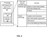
- Figure 4 shows exemplary information included in a COPE packet per some embodiments of the invention.
- An IP packet (452) may be transmitted between a client (e.g., the client node 252) and a server (e.g., the server node 256), and pass through an intermediate node (e.g., the COPE node 254) for a QUIC session.
- the IP packet (452) contains the COPE packet (456), e.g., in either its UDP payload, UDP option, or IPv6 Destination Header Extension as shown at reference 454.
- the COPE packet includes discovery information 458.
- the discovery information 458 included in the COPE packet includes two types - identification information (402) and features/functions (404).
- the identification information (402) may include one or more of the COPE node's global identifier or Common Name (CNAME), its node certificate, and optionally its IP address and/or port.
- CNAME Common Name
- the feature/function part of the information will contain a list of different features/functions the COPE node is able to perform along with the information required to perform those functions. The client can then decide what function it allows the COPE node to perform and exposes that information to the COPE node.
- the features/function may include the following:
- the endpoint and COPE node will agree on the feature usage.
- the encryption of the COPE packets may use the existing encryption algorithms known in the art.
- the encryption can use so-called hybrid encryption algorithm (e.g., Elliptic Curve Integrated Encryption Scheme (ECIES)) consisting of a key encapsulation mechanism and a data encapsulation mechanism) or other symmetric/asymmetric encryption algorithms.
- hybrid encryption algorithm e.g., Elliptic Curve Integrated Encryption Scheme (ECIES)
- ECIES Elliptic Curve Integrated Encryption Scheme
- FIG. 5 is a flow diagram showing the operations of an intermediate network device for in-band signaling according to the claimed invention.
- the intermediate network device may be the COPE node as discussed herein above.
- the network device receives a first packet within a UDP datagram, where the first packet is an initial packet for establishing a QUIC session between a client network device and a server network device.
- the initial packet is within an IP packet, which includes a UDP datagram.
- the initial packet is sourced from the client network device for the QUIC session, and the initial packet is a client's initial packet containing a crypto frame with a TLS Client hello (e.g., a client hello frame CHELLO).
- the initial packet is sourced from the server network device for the QUIC session, and wherein the initial packet contains a crypto frame with a TLS server hello (e.g., a server hello frame SHELLO).
- the network device inserts discovery information into a second packet within the IP packet, where the discovery information includes a set of features supported by the network device.
- the second packet may be included as a part of the UDP payload, a UDP option, or IPv6 Header Extension as explained herein.
- the network device first detects whether a second packet for discovery information exists in the received IP packet; and if it does, the network device may insert the discovery information when the frame size allows such insertion.
- the network device creates the second packet, inserts the discovery information in this second packet, and inserts it in the same UDP datagram as the QUIC initial packet, otherwise it may be inserted in a subsequent QUIC packet, or in the protected data field using UDP options and/or IPv6 Destination Header Extension within a UDP datagram.
- the network device encrypts the discovery information.
- the discovery information includes identity of the network device.
- the identity of the network device includes one or more of its global identifier or common name, its node certificate, and its IP address.
- the method further comprises: detecting whether a second packet for discovery information exists in the received IP packet, wherein: if no second packet exists in the received IP packet, the method comprises: creating a second packet, and inserting discovery information into the created second packet within the IP packet, and if a second packet does exist in the received IP packet, the method comprises: inserting the discovery information into the existing second packet within the IP packet.
- the network device transmits the IP packet after the inserting based on destination of the IP packet.
- the destination is the server network device when the UDP datagram contains the client's initial packet, and the destination is the client network device when the UDP datagram is the server's initial packet.
- the network device may establish a QUIC session with the client network device based on a response received from the same client network device.
- the client network device receives a UDP datagram that includes the discovery information (which is relayed by the server network device), and the client network device initiates a QUIC session with the network device.
- the QUIC session is established for the network device to perform performance enhancement features such as the ones discussed herein above relating to Figure 4 .
- the network device may establish a QUIC session with the server network device based on a response received from the same server network device.
- the discovery information indicates a set of features that the network device provides.
- the set of features includes one or more of a congestion control enhancement, a split or domain specific congestion control, traffic exposure, and a link to a more detailed set of features list.
- the encryption uses a public key of the source network device.
- the discovery information has a digital signature added by the network device inserting the discovery information.
- the network device obtains keying materials for the encryption from the source or destination network devices (e.g., the client or server network devices).
- FIG. 6 is a flow diagram showing the operations of a network device implementing a server of a QUIC session for in-band signaling per one embodiment of the invention.
- the network device implements a server node/network device (server) discussed herein above in one embodiment.
- the network device receives a first UDP datagram from a client network device for the server network device, wherein the first UDP datagram includes (1) a first packet for the QUIC session between a client network device and the network device and (2) a second packet for discovery information, where the second packet includes discovery information inserted by an intermediate network device.
- the discovery information inserted by the intermediate network device comprises the inserted information discussed herein above relating to Figure 4 .
- the first and second packets may be ordered differently in different embodiments, and they may not be consecutive packets within the first UDP datagram.
- the network device identifies the discovery information inserted by the intermediate network device from the second packet.
- the inserted information may be encrypted by the intermediate network device and not decryptable by the network device in one embodiment.
- the network device transmits a second UDP datagram toward the client network device upon identifying the client network device of the QUIC session, where one of the UDP datagrams received at the network device includes the inserted information.
- the network device identifies the intermediate network device that has inserted the discovery information in the second packet.
- the network device determines a performance enhancement feature (e.g., one or more of the ones discussed relating to Figure 4 ) for the QUIC session based on the inserted discovery information.
- a performance enhancement feature e.g., one or more of the ones discussed relating to Figure 4
- the network device may allow or deny usage of performance enhancement by the intermediate network device for the QUIC session.
- the network device may also remove one or more malfunctioning intermediate network devices from providing performance enhancement and/or functioning as a proxy for the QUIC session upon determining that the one or more intermediate network devices are malfunctioning based on its inserted discovery information in the second packet.
- FIG. 7 is a flow diagram showing the operations of a network device implementing a client of a QUIC session for in-band signaling per one embodiment of the invention.
- the network device implements a client node/network device (client) discussed herein above in one embodiment.
- the network device transmits a first UDP datagram toward a server network device, where the first UDP datagram includes a first packet for the QUIC session between the network device and a server network device and a second packet for discovery information.
- the first and second packets may be ordered differently in different embodiments, and they may not be consecutive packets within the UDP datagrams.
- the network device receives a second UDP datagram from the server network device, where the second UDP datagram includes a third packet for the QUIC session and a fourth packet including information inserted by the intermediate network device.
- the third packet may contain a server hello frame as discussed herein above.
- the network device may decrypt the packets included in the second UDP datagram and extract the inserted information.
- the network device identifies the intermediate network device using the certificate of the intermediate network device inserted in the first UDP datagram.
- the network device selects one or more of the set of performance enhancement features provided by the intermediate network device to be used for the QUIC session based on the inserted information in the fourth packet.
- the network device initiates a connection with the intermediate network devices as identified by the inserted information in the fourth packet.
- Figure 8A illustrates connectivity between network devices (NDs) within an exemplary network, as well as three exemplary implementations of the NDs, according to some embodiments of the invention.
- Figure 8A shows NDs 800A-H, and their connectivity by way of lines between 800A-800B, 800B-800C, 800C-800D, 800D-800E, 800E-800F, 800F-800G, and 800A-800G, as well as between 800H and each of 800A, 800C, 800D, and 800G.
- These NDs are physical devices, and the connectivity between these NDs can be wireless or wired (often referred to as a link).
- NDs 800A, 800E, and 800F An additional line extending from NDs 800A, 800E, and 800F illustrates that these NDs act as ingress and egress points for the network (and thus, these NDs are sometimes referred to as edge NDs; while the other NDs may be called core NDs).
- Two of the exemplary ND implementations in Figure 8A are: 1) a special-purpose network device 802 that uses custom application-specific integrated-circuits (ASICs) and a special-purpose operating system (OS); and 2) a general purpose network device 804 that uses common off-the-shelf (COTS) processors and a standard OS.
- ASICs application-specific integrated-circuits
- OS special-purpose operating system
- COTS common off-the-shelf
- the special-purpose network device 802 includes networking hardware 810 comprising a set of one or more processor(s) 812, forwarding resource(s) 814 (which typically include one or more ASICs and/or network processors), and physical network interfaces (NIs) 816 (through which network connections are made, such as those shown by the connectivity between NDs 800A-H), as well as non-transitory machine readable storage media 818 having stored therein networking software 820.
- the networking software 820 may be executed by the networking hardware 810 to instantiate a set of one or more networking software instance(s) 822.
- Each of the networking software instance(s) 822, and that part of the networking hardware 810 that executes that network software instance form a separate virtual network element 830A-R.
- Each of the virtual network element(s) (VNEs) 830A-R includes a control communication and configuration module 832A-R (sometimes referred to as a local control module or control communication module) and forwarding table(s) 834A-R, such that a given virtual network element (e.g., 830A) includes the control communication and configuration module (e.g., 832A), a set of one or more forwarding table(s) (e.g., 834A), and that portion of the networking hardware 810 that executes the virtual network element (e.g., 830A).
- the networking software 820 contains a middlebox performance enhancement coordinator (MPEC) 855.
- MPEC middlebox performance enhancement coordinator
- the middlebox performance enhancement coordinator 855 may perform operations as the sender, receiver, or COPE node in the operations described with reference to earlier figures. For example, when network device 802 serves as an intermediate network device on a path between a client network device and a server network device for a QUIC session, MPEC 855 performs operations relating to Figure 5 ; when it serves as the server network device, it performs operations relating to Figure 6 ; and when it serves as the source network device, it performs operations relating to Figure 7 .
- the special-purpose network device 802 is often physically and/or logically considered to include: 1) a ND control plane 824 (sometimes referred to as a control plane) comprising the processor(s) 812 that execute(s) the control communication and configuration module(s) 832A-R; and 2) a ND forwarding plane 826 (sometimes referred to as a forwarding plane, a data plane, or a media plane) comprising the forwarding resource(s) 814 that utilize the forwarding table(s) 834A-R and the physical NIs 816.
- a ND control plane 824 (sometimes referred to as a control plane) comprising the processor(s) 812 that execute(s) the control communication and configuration module(s) 832A-R
- a ND forwarding plane 826 sometimes referred to as a forwarding plane, a data plane, or a media plane
- the forwarding resource(s) 814 that utilize the forwarding table(s) 834A-R and the physical NIs 816.
- the ND control plane 824 (the processor(s) 812 executing the control communication and configuration module(s) 832A-R) is typically responsible for participating in controlling how data (e.g., packets) is to be routed (e.g., the next hop for the data and the outgoing physical NI for that data) and storing that routing information in the forwarding table(s) 834A-R, and the ND forwarding plane 826 is responsible for receiving that data on the physical NIs 816 and forwarding that data out to the appropriate ones of the physical NIs 816 based on the forwarding table(s) 834A-R.
- data e.g., packets
- the ND forwarding plane 826 is responsible for receiving that data on the physical NIs 816 and forwarding that data out to the appropriate ones of the physical NIs 816 based on the forwarding table(s) 834A-R.
- Figure 8B illustrates an exemplary way to implement the special-purpose network device 802 according to some embodiments of the invention.
- Figure 8B shows a special-purpose network device including cards 838 (typically hot pluggable). While in some embodiments the cards 838 are of two types (one or more that operate as the ND forwarding plane 826 (sometimes called line cards), and one or more that operate to implement the ND control plane 824 (sometimes called control cards)), alternative embodiments may combine functionality onto a single card and/or include additional card types (e.g., one additional type of card is called a service card, resource card, or multi-application card).
- additional card types e.g., one additional type of card is called a service card, resource card, or multi-application card.
- a service card can provide specialized processing (e.g., Layer 4 to Layer 7 services (e.g., firewall, Internet Protocol Security (IPsec), Secure Sockets Layer (SSL) / Transport Layer Security (TLS), Intrusion Detection System (IDS), peer-to-peer (P2P), Voice over IP (VoIP) Session Border Controller, Mobile Wireless Gateways (Gateway General Packet Radio Service (GPRS) Support Node (GGSN), Evolved Packet Core (EPC) Gateway)).
- Layer 4 to Layer 7 services e.g., firewall, Internet Protocol Security (IPsec), Secure Sockets Layer (SSL) / Transport Layer Security (TLS), Intrusion Detection System (IDS), peer-to-peer (P2P), Voice over IP (VoIP) Session Border Controller, Mobile Wireless Gateways (Gateway General Packet Radio Service (GPRS) Support Node (GGSN), Evolved Packet Core (EPC) Gateway)
- GPRS General Pack
- the general-purpose network device 804 includes hardware 840 comprising a set of one or more processor(s) 842 (which are often COTS processors) and physical NIs 846, as well as non-transitory machine-readable storage media 848 having stored therein software 850.
- the processor(s) 842 execute the software 850 to instantiate one or more sets of one or more applications 864A-R. While one embodiment does not implement virtualization, alternative embodiments may use different forms of virtualization.
- the virtualization layer 854 represents the kernel of an operating system (or a shim executing on a base operating system) that allows for the creation of multiple instances 862A-R called software containers that may each be used to execute one (or more) of the sets of applications 864A-R; where the multiple software containers (also called virtualization engines, virtual private servers, or jails) are user spaces (typically a virtual memory space) that are separate from each other and separate from the kernel space in which the operating system is run; and where the set of applications running in a given user space, unless explicitly allowed, cannot access the memory of the other processes.
- the multiple software containers also called virtualization engines, virtual private servers, or jails
- user spaces typically a virtual memory space
- the virtualization layer 854 represents a hypervisor (sometimes referred to as a virtual machine monitor (VMM)) or a hypervisor executing on top of a host operating system, and each of the sets of applications 864A-R is run on top of a guest operating system within an instance 862A-R called a virtual machine (which may in some cases be considered a tightly isolated form of software container) that is run on top of the hypervisor - the guest operating system and application may not know they are running on a virtual machine as opposed to running on a "bare metal" host electronic device, or through para-virtualization the operating system and/or application may be aware of the presence of virtualization for optimization purposes.
- a hypervisor sometimes referred to as a virtual machine monitor (VMM)
- VMM virtual machine monitor
- one, some, or all of the applications are implemented as unikernel(s), which can be generated by compiling directly with an application only a limited set of libraries (e.g., from a library operating system (LibOS) including drivers/libraries of OS services) that provide the particular OS services needed by the application.
- libraries e.g., from a library operating system (LibOS) including drivers/libraries of OS services
- unikernel can be implemented to run directly on hardware 840, directly on a hypervisor (in which case the unikernel is sometimes described as running within a LibOS virtual machine), or in a software container
- embodiments can be implemented fully with unikernels running directly on a hypervisor represented by virtualization layer 854, unikernels running within software containers represented by instances 862A-R, or as a combination of unikernels and the above-described techniques (e.g., unikernels and virtual machines both run directly on a hypervisor, unikernels and sets of applications that are run in different software containers).
- the networking software 850 includes a middlebox performance enhancement coordinator (MPEC) 855, whose operations are discussed herein relating to the network device 802.
- MPEC middlebox performance enhancement coordinator
- the virtual network element(s) 860A-R perform similar functionality to the virtual network element(s) 830A-R - e.g., similar to the control communication and configuration module(s) 832A and forwarding table(s) 834A (this virtualization of the hardware 840 is sometimes referred to as network function virtualization (NFV)).
- NFV network function virtualization
- CPE customer premise equipment
- each instance 862A-R corresponding to one VNE 860A-R
- alternative embodiments may implement this correspondence at a finer level granularity (e.g., line card virtual machines virtualize line cards, control card virtual machine virtualize control cards, etc.); it should be understood that the techniques described herein with reference to a correspondence of instances 862A-R to VNEs also apply to embodiments where such a finer level of granularity and/or unikernels are used.
- the virtualization layer 854 includes a virtual switch that provides similar forwarding services as a physical Ethernet switch. Specifically, this virtual switch forwards traffic between instances 862A-R and the physical NI(s) 846, as well as optionally between the instances 862A-R; in addition, this virtual switch may enforce network isolation between the VNEs 860A-R that by policy are not permitted to communicate with each other (e.g., by honoring virtual local area networks (VLANs)).
- VLANs virtual local area networks
- the third exemplary ND implementation in Figure 8A is a hybrid network device 806, which includes both custom ASICs/special-purpose OS and COTS processors/standard OS in a single ND or a single card within an ND.
- a platform VM i.e., a VM that that implements the functionality of the special-purpose network device 802 could provide for para-virtualization to the networking hardware present in the hybrid network device 806.
- each of the VNEs receives data on the physical NIs (e.g., 816, 846) and forwards that data out the appropriate ones of the physical NIs (e.g., 816, 846).
- a VNE implementing IP router functionality forwards IP packets on the basis of some of the IP header information in the IP packet; where IP header information includes source IP address, destination IP address, source port, destination port (where "source port” and “destination port” refer herein to protocol ports, as opposed to physical ports of a ND), transport protocol (e.g., user datagram protocol (UDP), Transmission Control Protocol (TCP), and differentiated services code point (DSCP) values.
- transport protocol e.g., user datagram protocol (UDP), Transmission Control Protocol (TCP), and differentiated services code point (DSCP) values.
- UDP user datagram protocol
- TCP Transmission Control Protocol
- DSCP differentiated services code point
- Figure 8C illustrates various exemplary ways in which VNEs may be coupled according to some embodiments of the invention.
- Figure 8C shows VNEs 870A.1-870A.P (and optionally VNEs 870A.Q-870A.R) implemented in ND 800A and VNE 870H.1 in ND 800H.
- VNEs 870A.1-P are separate from each other in the sense that they can receive packets from outside ND 800A and forward packets outside of ND 800A; VNE 870A.1 is coupled with VNE 870H.1, and thus they communicate packets between their respective NDs; VNE 870A.2-870A.3 may optionally forward packets between themselves without forwarding them outside of the ND 800A; and VNE 870A.P may optionally be the first in a chain of VNEs that includes VNE 870A.Q followed by VNE 870A.R (this is sometimes referred to as dynamic service chaining, where each of the VNEs in the series of VNEs provides a different service - e.g., one or more layer 4-7 network services). While Figure 8C illustrates various exemplary relationships between the VNEs, alternative embodiments may support other relationships (e.g., more/fewer VNEs, more/fewer dynamic service chains, multiple different dynamic service chains with some common VNEs and some different
- the NDs of Figure 8A may form part of the Internet or a private network; and other electronic devices (not shown; such as end user devices including workstations, laptops, netbooks, tablets, palm tops, mobile phones, smartphones, phablets, multimedia phones, Voice Over Internet Protocol (VOIP) phones, terminals, portable media players, GPS units, wearable devices, gaming systems, set-top boxes, Internet enabled household appliances) may be coupled to the network (directly or through other networks such as access networks) to communicate over the network (e.g., the Internet or virtual private networks (VPNs) overlaid on (e.g., tunneled through) the Internet) with each other (directly or through servers) and/or access content and/or services.
- VOIP Voice Over Internet Protocol
- Such content and/or services are typically provided by one or more servers (not shown) belonging to a service/content provider or one or more end user devices (not shown) participating in a peer-to-peer (P2P) service, and may include, for example, public webpages (e.g., free content, store fronts, search services), private webpages (e.g., username/password accessed webpages providing email services), and/or corporate networks over VPNs.
- end user devices may be coupled (e.g., through customer premise equipment coupled to an access network (wired or wirelessly)) to edge NDs, which are coupled (e.g., through one or more core NDs) to other edge NDs, which are coupled to electronic devices acting as servers.
- one or more of the electronic devices operating as the NDs in Figure 8A may also host one or more such servers (e.g., in the case of the general purpose network device 804, one or more of the software instances 862A-R may operate as servers; the same would be true for the hybrid network device 806; in the case of the special-purpose network device 802, one or more such servers could also be run on a virtualization layer executed by the processor(s) 812); in which case the servers are said to be co-located with the VNEs of that ND.
- the servers are said to be co-located with the VNEs of that ND.
- a virtual network is a logical abstraction of a physical network (such as that in Figure 8A ) that provides network services (e.g., L2 and/or L3 services).
- a virtual network can be implemented as an overlay network (sometimes referred to as a network virtualization overlay) that provides network services (e.g., layer 2 (L2, data link layer) and/or layer 3 (L3, network layer) services) over an underlay network (e.g., an L3 network, such as an Internet Protocol (IP) network that uses tunnels (e.g., generic routing encapsulation (GRE), layer 2 tunneling protocol (L2TP), IPSec) to create the overlay network).
- IP Internet Protocol
- a network virtualization edge sits at the edge of the underlay network and participates in implementing the network virtualization; the network-facing side of the NVE uses the underlay network to tunnel frames to and from other NVEs; the outward-facing side of the NVE sends and receives data to and from systems outside the network.
- a virtual network instance is a specific instance of a virtual network on a NVE (e.g., a NE/VNE on an ND, a part of a NE/VNE on a ND where that NE/VNE is divided into multiple VNEs through emulation); one or more VNIs can be instantiated on an NVE (e.g., as different VNEs on an ND).
- a virtual access point is a logical connection point on the NVE for connecting external systems to a virtual network; a VAP can be physical or virtual ports identified through logical interface identifiers (e.g., a VLAN ID).
- Examples of network services include: 1) an Ethernet LAN emulation service (an Ethernet-based multipoint service similar to an Internet Engineering Task Force (IETF) Multiprotocol Label Switching (MPLS) or Ethernet VPN (EVPN) service) in which external systems are interconnected across the network by a LAN environment over the underlay network (e.g., an NVE provides separate L2 VNIs (virtual switching instances) for different such virtual networks, and L3 (e.g., IP/MPLS) tunneling encapsulation across the underlay network); and 2) a virtualized IP forwarding service (similar to IETF IP VPN (e.g., Border Gateway Protocol (BGP)/MPLS IPVPN) from a service definition perspective) in which external systems are interconnected across the network by an L3 environment over the underlay network (e.g., an NVE provides separate L3 VNIs (forwarding and routing instances) for different such virtual networks, and L3 (e.g., IP/MPLS) tunneling encapsulation across the underlay network)).
- Network services may also include quality of service capabilities (e.g., traffic classification marking, traffic conditioning and scheduling), security capabilities (e.g., filters to protect customer premises from network - originated attacks, to avoid malformed route announcements), and management capabilities (e.g., full detection and processing).
- quality of service capabilities e.g., traffic classification marking, traffic conditioning and scheduling
- security capabilities e.g., filters to protect customer premises from network - originated attacks, to avoid malformed route announcements
- management capabilities e.g., full detection and processing
- Figure 8D illustrates a network with a single network element on each of the NDs of Figure 8A , and within this straight forward approach contrasts a traditional distributed approach (commonly used by traditional routers) with a centralized approach for maintaining reachability and forwarding information (also called network control), according to some embodiments of the invention.
- Figure 8D illustrates network elements (NEs) 870A-H with the same connectivity as the NDs 800A-H of Figure 8A .
- Figure 8D illustrates that the distributed approach 872 distributes responsibility for generating the reachability and forwarding information across the NEs 870A-H; in other words, the process of neighbor discovery and topology discovery is distributed.
- the control communication and configuration module(s) 832A-R of the ND control plane 824 typically include a reachability and forwarding information module to implement one or more routing protocols (e.g., an exterior gateway protocol such as Border Gateway Protocol (BGP), Interior Gateway Protocol(s) (IGP) (e.g., Open Shortest Path First (OSPF), Intermediate System to Intermediate System (IS-IS), Routing Information Protocol (RIP), Label Distribution Protocol (LDP), Resource Reservation Protocol (RSVP) (including RSVP-Traffic Engineering (TE): Extensions to RSVP for LSP Tunnels and Generalized Multi-Protocol Label Switching (GMPLS) Signaling RSVP-TE)) that communicate with other NEs to exchange routes, and then selects those routes based on one or more routing metrics.
- Border Gateway Protocol BGP
- IGP Interior Gateway Protocol
- OSPF Open Shortest Path First
- IS-IS Intermediate System to Intermediate System
- RIP Routing Information Protocol
- LDP Label Distribution Protocol
- RSVP Resource Reservation Protocol
- TE RSVP-Traffic Engineering
- GPLS
- the NEs 870A-H e.g., the processor(s) 812 executing the control communication and configuration module(s) 832A-R
- Routes and adjacencies are stored in one or more routing structures (e.g., Routing Information Base (RIB), Label Information Base (LIB), one or more adjacency structures) on the ND control plane 824.
- routing structures e.g., Routing Information Base (RIB), Label Information Base (LIB), one or more adjacency structures
- the ND control plane 824 programs the ND forwarding plane 826 with information (e.g., adjacency and route information) based on the routing structure(s). For example, the ND control plane 824 programs the adjacency and route information into one or more forwarding table(s) 834A-R (e.g., Forwarding Information Base (FIB), Label Forwarding Information Base (LFIB), and one or more adjacency structures) on the ND forwarding plane 826.
- the ND can store one or more bridging tables that are used to forward data based on the layer 2 information in that data. While the above example uses the special-purpose network device 802, the same distributed approach 872 can be implemented on the general-purpose network device 804 and the hybrid network device 806.
- FIG. 8D illustrates that a centralized approach 874 (also known as software defined networking (SDN)) that decouples the system that makes decisions about where traffic is sent from the underlying systems that forwards traffic to the selected destination.
- the illustrated centralized approach 874 has the responsibility for the generation of reachability and forwarding information in a centralized control plane 876 (sometimes referred to as a SDN control module, controller, network controller, OpenFlow controller, SDN controller, control plane node, network virtualization authority, or management control entity), and thus the process of neighbor discovery and topology discovery is centralized.
- a centralized control plane 876 sometimes referred to as a SDN control module, controller, network controller, OpenFlow controller, SDN controller, control plane node, network virtualization authority, or management control entity
- the centralized control plane 876 has a south bound interface 882 with a data plane 880 (sometime referred to the infrastructure layer, network forwarding plane, or forwarding plane (which should not be confused with a ND forwarding plane)) that includes the NEs 870A-H (sometimes referred to as switches, forwarding elements, data plane elements, or nodes).
- the centralized control plane 876 includes a network controller 878, which includes a centralized reachability and forwarding information module 879 that determines the reachability within the network and distributes the forwarding information to the NEs 870A-H of the data plane 880 over the south bound interface 882 (which may use the OpenFlow protocol).
- centralized reachability and forwarding information module 879 includes an encryption coordinator 875, which may coordinate the acquisition of the keying materials (e.g., keys and cipher algorithms) necessary to secure the communication between an intermediate network device and an endpoint (client or server) network device as discussed herein above.
- keying materials e.g., keys and cipher algorithms
- the ND control plane 824 (the processor(s) 812 executing the control communication and configuration module(s) 832A-R) performs its responsibility for participating in controlling how data (e.g., packets) is to be routed (e.g., the next hop for the data and the outgoing physical NI for that data) through the control agent communicating with the centralized control plane 876 to receive the forwarding information (and in some cases, the reachability information) from the centralized reachability and forwarding information module 879 (it should be understood that in some embodiments of the invention, the control communication and configuration module(s) 832A-R, in addition to communicating with the centralized control plane 876, may also play some role in determining reachability and/or calculating forwarding information - albeit less so than in the case of a distributed approach; such embodiments are generally considered to fall under the centralized approach 874 but may also be considered a hybrid approach).
- data e.g., packets
- the control agent communicating with the centralized control plane 876 to receive the forwarding information
- the same centralized approach 874 can be implemented with the general purpose network device 804 (e.g., each of the VNE 860A-R performs its responsibility for controlling how data (e.g., packets) is to be routed (e.g., the next hop for the data and the outgoing physical NI for that data) by communicating with the centralized control plane 876 to receive the forwarding information (and in some cases, the reachability information) from the centralized reachability and forwarding information module 879; it should be understood that in some embodiments of the invention, the VNEs 860A-R, in addition to communicating with the centralized control plane 876, may also play some role in determining reachability and/or calculating forwarding information - albeit less so than in the case of a distributed approach) and the hybrid network device 806.
- the general purpose network device 804 e.g., each of the VNE 860A-R performs its responsibility for controlling how data (e.g., packets) is to be routed (e.g., the next hop for
- NFV is able to support SDN by providing an infrastructure upon which the SDN software can be run
- NFV and SDN both aim to make use of commodity server hardware and physical switches.
- Figure 8D also shows that the centralized control plane 876 has a north bound interface 884 to an application layer 886, in which resides application(s) 888.
- the centralized control plane 876 has the ability to form virtual networks 892 (sometimes referred to as a logical forwarding plane, network services, or overlay networks (with the NEs 870A-H of the data plane 880 being the underlay network)) for the application(s) 888.
- virtual networks 892 sometimes referred to as a logical forwarding plane, network services, or overlay networks (with the NEs 870A-H of the data plane 880 being the underlay network)
- the centralized control plane 876 maintains a global view of all NDs and configured NEs/VNEs, and it maps the virtual networks to the underlying NDs efficiently (including maintaining these mappings as the physical network changes either through hardware (ND, link, or ND component) failure, addition, or removal).
- Figure 8D shows the distributed approach 872 separate from the centralized approach 874
- the effort of network control may be distributed differently or the two combined in certain embodiments of the invention.
- embodiments may generally use the centralized approach (SDN) 874, but have certain functions delegated to the NEs (e.g., the distributed approach may be used to implement one or more of fault monitoring, performance monitoring, protection switching, and primitives for neighbor and/or topology discovery); or 2) embodiments of the invention may perform neighbor discovery and topology discovery via both the centralized control plane and the distributed protocols, and the results compared to raise exceptions where they do not agree.
- SDN centralized approach
- Such embodiments are generally considered to fall under the centralized approach 874 but may also be considered a hybrid approach.
- Figure 8D illustrates the simple case where each of the NDs 800A-H implements a single NE 870A-H
- the network control approaches described with reference to Figure 8D also work for networks where one or more of the NDs 800A-H implement multiple VNEs (e.g., VNEs 830A-R, VNEs 860A-R, those in the hybrid network device 806).
- the network controller 878 may also emulate the implementation of multiple VNEs in a single ND.
- the network controller 878 may present the implementation of a VNE/NE in a single ND as multiple VNEs in the virtual networks 892 (all in the same one of the virtual network(s) 892, each in different ones of the virtual network(s) 892, or some combination).
- the network controller 878 may cause an ND to implement a single VNE (a NE) in the underlay network, and then logically divide up the resources of that NE within the centralized control plane 876 to present different VNEs in the virtual network(s) 892 (where these different VNEs in the overlay networks are sharing the resources of the single VNE/NE implementation on the ND in the underlay network).
- Figures 8E and 8F respectively illustrate exemplary abstractions of NEs and VNEs that the network controller 878 may present as part of different ones of the virtual networks 892.
- Figure 8E illustrates the simple case of where each of the NDs 800A-H implements a single NE 870A-H (see Figure 8D ), but the centralized control plane 876 has abstracted multiple of the NEs in different NDs (the NEs 870A-C and G-H) into (to represent) a single NE 870I in one of the virtual network(s) 892 of Figure 8D , according to some embodiments of the invention.
- Figure 8E shows that in this virtual network, the NE 870I is coupled to NE 870D and 870F, which are both still coupled to NE 870E.
- Figure 8F illustrates a case where multiple VNEs (VNE 870A.1 and VNE 870H.1) are implemented on different NDs (ND 800A and ND 800H) and are coupled to each other, and where the centralized control plane 876 has abstracted these multiple VNEs such that they appear as a single VNE 870T within one of the virtual networks 892 of Figure 8D , according to some embodiments of the invention.
- the abstraction of a NE or VNE can span multiple NDs.
- the electronic device(s) running the centralized control plane 876 may be implemented in a variety of ways (e.g., a special purpose device, a general-purpose (e.g., COTS) device, or hybrid device). These electronic device(s) would similarly include processor(s), a set or one or more physical NIs, and a non-transitory machine-readable storage medium having stored thereon the centralized control plane software.
- Standards such as OpenFlow define the protocols used for the messages, as well as a model for processing the packets.
- the model for processing packets includes header parsing, packet classification, and making forwarding decisions. Header parsing describes how to interpret a packet based upon a well-known set of protocols. Some protocol fields are used to build a match structure (or key) that will be used in packet classification (e.g., a first key field could be a source media access control (MAC) address, and a second key field could be a destination MAC address).
- MAC media access control
- Packet classification involves executing a lookup in memory to classify the packet by determining which entry (also referred to as a forwarding table entry or flow entry) in the forwarding tables best matches the packet based upon the match structure, or key, of the forwarding table entries. It is possible that many flows represented in the forwarding table entries can correspond/match to a packet; in this case the system is typically configured to determine one forwarding table entry from the many according to a defined scheme (e.g., selecting a first forwarding table entry that is matched).
- Forwarding table entries include both a specific set of match criteria (a set of values or wildcards, or an indication of what portions of a packet should be compared to a particular value/values/wildcards, as defined by the matching capabilities - for specific fields in the packet header, or for some other packet content), and a set of one or more actions for the data plane to take on receiving a matching packet. For example, an action may be to push a header onto the packet, for the packet using a particular port, flood the packet, or simply drop the packet.
- TCP transmission control protocol
- an unknown packet for example, a "missed packet” or a "match-miss” as used in OpenFlow parlance
- the packet (or a subset of the packet header and content) is typically forwarded to the centralized control plane 876.
- the centralized control plane 876 will then program forwarding table entries into the data plane 880 to accommodate packets belonging to the flow of the unknown packet. Once a specific forwarding table entry has been programmed into the data plane 880 by the centralized control plane 876, the next packet with matching credentials will match that forwarding table entry and take the set of actions associated with that matched entry.
- a network interface may be physical or virtual; and in the context of IP, an interface address is an IP address assigned to a NI, be it a physical NI or virtual NI.
- a virtual NI may be associated with a physical NI, with another virtual interface, or stand on its own (e.g., a loopback interface, a point-to-point protocol interface).
- a NI physical or virtual
- a loopback interface (and its loopback address) is a specific type of virtual NI (and IP address) of a NE/VNE (physical or virtual) often used for management purposes; where such an IP address is referred to as the nodal loopback address.
- IP addresses of that ND are referred to as IP addresses of that ND; at a more granular level, the IP address(es) assigned to NI(s) assigned to a NE/VNE implemented on a ND can be referred to as IP addresses of that NE/VNE.
- Next hop selection by the routing system for a given destination may resolve to one path (that is, a routing protocol may generate one next hop on a shortest path); but if the routing system determines there are multiple viable next hops (that is, the routing protocol generated forwarding solution offers more than one next hop on a shortest path - multiple equal cost next hops), some additional criteria is used - for instance, in a connectionless network, Equal Cost Multi Path (ECMP) (also known as Equal Cost Multi Pathing, multipath forwarding and IP multipath) may be used (e.g., typical implementations use as the criteria particular header fields to ensure that the packets of a particular packet flow are always forwarded on the same next hop to preserve packet flow ordering).
- ECMP Equal Cost Multi Path
- a packet flow is defined as a set of packets that share an ordering constraint.
- the set of packets in a particular TCP transfer sequence need to arrive in order, else the TCP logic will interpret the out of order delivery as congestion and slow the TCP transfer rate down.
- a Layer 3 (L3) Link Aggregation (LAG) link is a link directly connecting two NDs with multiple IP-addressed link paths (each link path is assigned a different IP address), and a load distribution decision across these different link paths is performed at the ND forwarding plane; in which case, a load distribution decision is made between the link paths.
- L3 Link Aggregation (LAG) link is a link directly connecting two NDs with multiple IP-addressed link paths (each link path is assigned a different IP address), and a load distribution decision across these different link paths is performed at the ND forwarding plane; in which case, a load distribution decision is made between the link paths.
- AAA authentication, authorization, and accounting
- RADIUS Remote Authentication Dial-In User Service
- Diameter Diameter
- TACACS+ Terminal Access Controller Access Control System Plus
- AAA can be provided through a client/server model, where the AAA client is implemented on a ND and the AAA server can be implemented either locally on the ND or on a remote electronic device coupled with the ND.
- Authentication is the process of identifying and verifying a subscriber. For instance, a subscriber might be identified by a combination of a username and a password or through a unique key.
- Authorization determines what a subscriber can do after being authenticated, such as gaining access to certain electronic device information resources (e.g., through the use of access control policies). Accounting is recording user activity.
- end user devices may be coupled (e.g., through an access network) through an edge ND (supporting AAA processing) coupled to core NDs coupled to electronic devices implementing servers of service/content providers.
- AAA processing is performed to identify for a subscriber the subscriber record stored in the AAA server for that subscriber.
- a subscriber record includes a set of attributes (e.g., subscriber name, password, authentication information, access control information, rate-limiting information, policing information) used during processing of that subscriber's traffic.
- Certain NDs internally represent end user devices (or sometimes customer premise equipment (CPE) such as a residential gateway (e.g., a router, modem)) using subscriber circuits.
- CPE customer premise equipment
- a subscriber circuit uniquely identifies within the ND a subscriber session and typically exists for the lifetime of the session.
- a ND typically allocates a subscriber circuit when the subscriber connects to that ND, and correspondingly de-allocates that subscriber circuit when that subscriber disconnects.
- Each subscriber session represents a distinguishable flow of packets communicated between the ND and an end user device (or sometimes CPE such as a residential gateway or modem) using a protocol, such as the point-to-point protocol over another protocol (PPPoX) (e.g., where X is Ethernet or Asynchronous Transfer Mode (ATM)), Ethernet, 802.1Q Virtual LAN (VLAN), Internet Protocol, or ATM).
- PPPoX point-to-point protocol over another protocol
- a subscriber session can be initiated using a variety of mechanisms (e.g., manual provisioning a dynamic host configuration protocol (DHCP), DHCP/client-less internet protocol service (CLIPS) or Media Access Control (MAC) address tracking).
- DHCP dynamic host configuration protocol
- CLIPS client-less internet protocol service
- MAC Media Access Control
- the point-to-point protocol is commonly used for digital subscriber line (DSL) services and requires installation of a PPP client that enables the subscriber to enter a username and a password, which in turn may be used to select a subscriber record.
- DHCP digital subscriber line
- a username typically is not provided; but in such situations other information (e.g., information that includes the MAC address of the hardware in the end user device (or CPE)) is provided.
- CPE end user device
- a virtual circuit synonymous with virtual connection and virtual channel, is a connection-oriented communication service that is delivered by means of packet mode communication.
- Virtual circuit communication resembles circuit switching, since both are connection oriented, meaning that in both cases data is delivered in correct order, and signaling overhead is required during a connection establishment phase.
- Virtual circuits may exist at different layers. For example, at layer 4, a connection-oriented transport layer datalink protocol such as Transmission Control Protocol (TCP) may rely on a connectionless packet switching network layer protocol such as IP, where different packets may be routed over different paths, and thus be delivered out of order.
- TCP Transmission Control Protocol
- IP connectionless packet switching network layer protocol
- the virtual circuit is identified by the source and destination network socket address pair, i.e., the sender and receiver IP address and port number.
- TCP includes segment numbering and reordering on the receiver side to prevent out-of-order delivery.
- Virtual circuits are also possible at Layer 3 (network layer) and Layer 2 (datalink layer); such virtual circuit protocols are based on connection-oriented packet switching, meaning that data is always delivered along the same network path, i.e., through the same NEs/VNEs.
- the packets are not routed individually and complete addressing information is not provided in the header of each data packet; only a small virtual channel identifier (VCI) is required in each packet; and routing information is transferred to the NEs/VNEs during the connection establishment phase; switching only involves looking up the virtual channel identifier in a table rather than analyzing a complete address.
- VCI virtual channel identifier
- VCI virtual channel identifier
- ATM Asynchronous Transfer Mode
- VPN virtual path identifier
- VCI virtual channel identifier
- VCI virtual channel identifier
- GPRS General Packet Radio Service
- MPLS Multiprotocol label switching
- Certain NDs use a hierarchy of circuits.
- the leaf nodes of the hierarchy of circuits are subscriber circuits.
- the subscriber circuits have parent circuits in the hierarchy that typically represent aggregations of multiple subscriber circuits, and thus the network segments and elements used to provide access network connectivity of those end user devices to the ND.
- These parent circuits may represent physical or logical aggregations of subscriber circuits (e.g., a virtual local area network (VLAN), a permanent virtual circuit (PVC) (e.g., for Asynchronous Transfer Mode (ATM)), a circuit-group, a channel, a pseudo-wire, a physical NI of the ND, and a link aggregation group).
- VLAN virtual local area network
- PVC permanent virtual circuit
- ATM Asynchronous Transfer Mode
- a circuit-group is a virtual construct that allows various sets of circuits to be grouped together for configuration purposes; for example, aggregate rate control.
- a pseudo-wire is an emulation of a layer 2 point-to-point connection-oriented service.
- a link aggregation group is a virtual construct that merges multiple physical NIs for purposes of bandwidth aggregation and redundancy.
- the parent circuits physically or logically encapsulate the subscriber circuits.
- Each VNE e.g., a virtual router, a virtual bridge (which may act as a virtual switch instance in a Virtual Private LAN Service (VPLS)) is typically independently administrable.
- each of the virtual routers may share system resources but is separate from the other virtual routers regarding its management domain, AAA (authentication, authorization, and accounting) name space, IP address, and routing database(s).
- AAA authentication, authorization, and accounting
- Multiple VNEs may be employed in an edge ND to provide direct network access and/or different classes of services for subscribers of service and/or content providers.
- interfaces that are independent of physical NIs may be configured as part of the VNEs to provide higher-layer protocol and service information (e.g., Layer 3 addressing).
- the subscriber records in the AAA server identify, in addition to the other subscriber configuration requirements, to which context (e.g., which of the VNEs/NEs) the corresponding subscribers should be bound within the ND.
- a binding forms an association between a physical entity (e.g., physical NI, channel) or a logical entity (e.g., circuit such as a subscriber circuit or logical circuit (a set of one or more subscriber circuits)) and a context's interface over which network protocols (e.g., routing protocols, bridging protocols) are configured for that context. Subscriber data flows on the physical entity when some higher-layer protocol interface is configured and associated with that physical entity.
- a physical entity e.g., physical NI, channel
- a logical entity e.g., circuit such as a subscriber circuit or logical circuit (a set of one or more subscriber circuits)
- network protocols e.g., routing protocols, bridging protocols
Landscapes
- Engineering & Computer Science (AREA)
- Computer Security & Cryptography (AREA)
- Computer Networks & Wireless Communication (AREA)
- Signal Processing (AREA)
- Computer Hardware Design (AREA)
- Computing Systems (AREA)
- General Engineering & Computer Science (AREA)
- Data Exchanges In Wide-Area Networks (AREA)
Claims (15)
- Verfahren, das von einer Netzwerkvorrichtung durchgeführt wird, die sich auf einem Pfad zwischen einer Client-Netzwerkvorrichtung und einer Server-Netzwerkvorrichtung befindet, wobei das Verfahren Folgendes umfasst:Empfangen (502) eines ersten Pakets innerhalb eines Datagramms eines Benutzer-Datagrammprotokolls, UDP, wobei das erste Paket ein Anfangspaket für eine QUIC-Sitzung zwischen der Client- und der Server-Netzwerkvorrichtung ist und das UDP-Datagramm sich innerhalb eines Internetprotokollpakets, IP-Pakets, befindet;Erfassen, ob ein zweites Paket für Erkennungsinformationen in dem empfangenen IP-Paket vorhanden ist,wobei:das Verfahren, wenn kein zweites Paket in dem empfangenen IP-Paket vorhanden ist, Folgendes umfasst:Erstellen eines zweiten Pakets; undEinfügen (504) von Erkennungsinformationen in das erstellte zweite Paket innerhalb des IP-Pakets; unddas Verfahren, wenn ein zweites Paket in dem empfangenen IP-Paket vorhanden ist, Folgendes umfasst:
Einfügen der Erkennungsinformationen in das vorhandene zweite Paket innerhalb des IP-Pakets, und wobei die Erkennungsinformationen einen Satz von Merkmalen umfassen, der von der Netzwerkvorrichtung unterstützt wird; undSenden (506) des IP-Pakets nach dem Einfügen basierend auf dem Ziel des IP-Pakets. - Verfahren nach Anspruch 1, wobei der Satz von Merkmalen eines oder mehrere von einer Überlaststeuerungsverbesserung, einer geteilten oder domänenspezifischen Überlaststeuerung, einer Verkehrsbelastung und einem Link zu einem detaillierteren Merkmalslistensatz umfasst.
- Verfahren nach Anspruch 1 oder 2, wobei die Erkennungsinformationen eine Identität der Netzwerkvorrichtung umfassen.
- Verfahren nach Anspruch 3, wobei die Identität der Netzwerkvorrichtung eines oder mehrere von ihrer globalen Kennung oder ihrem allgemeinen Namen, ihrem Knotenzertifikat und ihrem IP-Adresse umfasst.
- Verfahren nach Anspruch 1 oder 2, wobei das erste Paket von der Client-Netzwerkvorrichtung für die QUIC-Sitzung bezogen wird und wobei das erste Paket einen Client-Hello-Rahmen enthält.
- Verfahren nach Anspruch 1 oder 2, wobei das erste Paket von der Server-Netzwerkvorrichtung für die QUIC-Sitzung bezogen wird und wobei das erste Paket einen Sever-Hello-Rahmen enthält.
- Verfahren nach Anspruch 1 oder 2, wobei das erste und das zweite Paket in derselben UDP-Nutzlast umfasst sind.
- Verfahren nach Anspruch 1 oder 2, wobei die Erkennungsinformationen verschlüsselt sind und wobei die Verschlüsselung einen öffentlichen Schlüssel der Quellnetzwerkvorrichtung verwendet.
- Verfahren nach Anspruch 8, wobei die Netzwerkvorrichtung Schlüsselmaterialien zur Verschlüsselung von der Client- oder der Server-Netzwerkvorrichtung erhält.
- Verfahren nach Anspruch 1 oder 2, wobei die Erkennungsinformationen eine digitale Signatur aufweisen, die von der Netzwerkvorrichtung, die die Erkennungsinformationen einfügt, hinzugefügt wird.
- Netzwerkvorrichtung (802, 804), umfassend:
einen Prozessor (812, 842) und ein nichtflüchtiges computerlesbares Speichermedium (818, 848), das Anweisungen bereitstellt, die bei Ausführung durch den Prozessor die Netzwerkvorrichtung veranlassen, Folgendes durchzuführen:Empfangen (502) eines ersten Pakets innerhalb eines Datagramms eines Benutzer-Datagrammprotokolls, UDP, wobei das erste Paket ein Anfangspaket für eine QUIC-Sitzung zwischen einer Client-Netzwerkvorrichtung und einer Server-Netzwerkvorrichtung ist und das UDP-Datagramm sich innerhalb eines Internetprotokollpakets, IP-Pakets, befindet;Erfassen, ob ein zweites Paket für Erkennungsinformationen in dem empfangenen IP-Paket vorhanden ist, wobei:das Verfahren, wenn kein zweites Paket in dem empfangenen IP-Paket vorhanden ist, Folgendes umfasst:Erstellen eines zweiten Pakets; undEinfügen (504) von Erkennungsinformationen in das erstellte zweite Paket innerhalb des IP-Pakets; unddas Verfahren, wenn ein zweites Paket in dem empfangenen IP-Paket vorhanden ist, Folgendes umfasst:
Einfügen der Erkennungsinformationen in das vorhandene zweite Paket innerhalb des IP-Pakets, und wobei die Erkennungsinformationen einen Satz von Merkmalen umfassen, der von der Netzwerkvorrichtung unterstützt wird; undSenden (506) des IP-Pakets nach dem Einfügen basierend auf dem Ziel des IP-Pakets. - Netzwerkvorrichtung nach Anspruch 11, wobei der Satz von Merkmalen eines oder mehrere von einer Überlaststeuerungsverbesserung, einer geteilten oder domänenspezifischen Überlaststeuerung, einer Verkehrsbelastung und einem Link zu einem detaillierteren Merkmalslistensatz umfasst.
- Netzwerkvorrichtung nach Anspruch 11 oder 12, wobei die Erkennungsinformationen eine Identität der Netzwerkvorrichtung umfassen.
- Netzwerkvorrichtung nach Anspruch 13, wobei die Identität der Netzwerkvorrichtung eines oder mehrere von ihrer globalen Kennung oder ihrem allgemeinen Namen, ihrem Knotenzertifikat und ihrem IP-Adresse umfasst.
- Nichtflüchtiges computerlesbares Speichermedium (818, 848), das Anweisungen bereitstellt, die bei Ausführung eine Netzwerkvorrichtung veranlassen, Folgendes durchzuführen:Empfangen (502) eines ersten Pakets innerhalb eines Datagramms eines Benutzer-Datagrammprotokolls, UDP, wobei das erste Paket ein Anfangspaket für eine QUIC-Sitzung zwischen einer Client-Netzwerkvorrichtung und einer Server-Netzwerkvorrichtung ist und das UDP-Datagramm innerhalb eines Internetprotokollpakets, IP-Pakets, befindet;Erfassen, ob ein zweites Paket für Erkennungsinformationen in dem empfangenen IP-Paket vorhanden ist, wobei:das Verfahren, wenn kein zweites Paket in dem empfangenen IP-Paket vorhanden ist, Folgendes umfasst:Erstellen eines zweiten Pakets; undEinfügen (504) von Erkennungsinformationen in das erstellte zweite Paket innerhalb des IP-Pakets; unddas Verfahren, wenn ein zweites Paket in dem empfangenen IP-Paket vorhanden ist, Folgendes umfasst:
Einfügen der Erkennungsinformationen in das vorhandene zweite Paket innerhalb des IP-Pakets, und wobei die Erkennungsinformationen einen Satz von Merkmalen umfassen, der von der Netzwerkvorrichtung unterstützt wird; undSenden (506) des IP-Pakets nach dem Einfügen basierend auf dem Ziel des IP-Pakets.
Applications Claiming Priority (1)
| Application Number | Priority Date | Filing Date | Title |
|---|---|---|---|
| PCT/IB2019/056180 WO2021009553A1 (en) | 2019-07-18 | 2019-07-18 | Method and system for in-band signaling in a quic session |
Publications (3)
| Publication Number | Publication Date |
|---|---|
| EP4000231A1 EP4000231A1 (de) | 2022-05-25 |
| EP4000231C0 EP4000231C0 (de) | 2025-03-05 |
| EP4000231B1 true EP4000231B1 (de) | 2025-03-05 |
Family
ID=67841118
Family Applications (1)
| Application Number | Title | Priority Date | Filing Date |
|---|---|---|---|
| EP19762478.6A Active EP4000231B1 (de) | 2019-07-18 | 2019-07-18 | Verfahren und system zur bandinternen signalisierung in einer quic-sitzung |
Country Status (2)
| Country | Link |
|---|---|
| EP (1) | EP4000231B1 (de) |
| WO (1) | WO2021009553A1 (de) |
Families Citing this family (19)
| Publication number | Priority date | Publication date | Assignee | Title |
|---|---|---|---|---|
| US11425043B2 (en) * | 2020-06-16 | 2022-08-23 | T-Mobile Usa, Inc. | Duplex load balancing for massive IoT applications |
| US12363041B2 (en) * | 2020-06-26 | 2025-07-15 | Telefonaktiebolaget Lm Ericsson (Publ) | Policy provisioning to a mobile communication system |
| US12114250B2 (en) | 2021-04-26 | 2024-10-08 | Arrcus Inc. | Selective importing of UE addresses to VRF in 5G networks |
| CN115334138B (zh) * | 2021-04-26 | 2023-09-01 | 华为技术有限公司 | Quic数据传输方法、装置、客户端及服务端 |
| US12063583B2 (en) | 2021-04-26 | 2024-08-13 | Arrcus Inc. | Use of IP networks for routing of cellular data packets |
| US11849381B2 (en) | 2021-04-26 | 2023-12-19 | Arrcus Inc. | Use of IP networks for routing of cellular data packets |
| US11632692B2 (en) * | 2021-04-26 | 2023-04-18 | Arrcus Inc. | Use of IP networks for routing of cellular data packets |
| US11924299B2 (en) | 2021-09-15 | 2024-03-05 | Cisco Technology, Inc. | QUIC and anycast proxy resiliency |
| WO2023044174A1 (en) | 2021-09-15 | 2023-03-23 | Cisco Technology, Inc. | Policy expressions using quic connection identifiers |
| US12069103B2 (en) | 2022-02-23 | 2024-08-20 | Cisco Technology, Inc. | Implementing policy based on unique addresses or ports |
| US12170644B2 (en) | 2022-02-23 | 2024-12-17 | Cisco Technology, Inc. | Binding flows to unique addresses or ports |
| CN114710568B (zh) * | 2022-04-28 | 2023-12-01 | 中移(杭州)信息技术有限公司 | 音视频数据通信方法、设备及存储介质 |
| CN115297098B (zh) * | 2022-08-04 | 2024-08-16 | 北京沃东天骏信息技术有限公司 | 边缘服务获取方法和装置、边缘计算系统、介质、设备 |
| US12483506B2 (en) * | 2022-09-30 | 2025-11-25 | Comcast Cable Communications, Llc | Methods and apparatuses for handling end-to-end encryption |
| CN116112436A (zh) * | 2022-12-21 | 2023-05-12 | 山东省计算中心(国家超级计算济南中心) | 一种基于quic传输协议的主动连接迁移方法及系统 |
| WO2024152336A1 (en) * | 2023-01-20 | 2024-07-25 | Zte Corporation | Reporting quic connection information to network |
| US12418578B2 (en) | 2023-03-15 | 2025-09-16 | Cisco Technology, Inc. | Prioritization of individual channels within multiplexed streams for zero trust network access (ZTNA) |
| CN117729025A (zh) * | 2023-12-20 | 2024-03-19 | 天翼数字生活科技有限公司 | 一种请求头增强系统、方法、设备和存储介质 |
| CN120582784B (zh) * | 2025-08-01 | 2025-10-14 | 之江实验室 | 一种面向卫星通信的量子安全通信方法、电子设备、介质 |
Family Cites Families (2)
| Publication number | Priority date | Publication date | Assignee | Title |
|---|---|---|---|---|
| US10904219B2 (en) * | 2016-03-02 | 2021-01-26 | Telefonaktiebolaget Lm Ericsson (Publ) | Transport relay in communications network |
| WO2019037852A1 (en) * | 2017-08-24 | 2019-02-28 | Telefonaktiebolaget Lm Ericsson (Publ) | IMPROVED DATA TRANSMISSION IN WIRELESS COMMUNICATION NETWORKS |
-
2019
- 2019-07-18 WO PCT/IB2019/056180 patent/WO2021009553A1/en not_active Ceased
- 2019-07-18 EP EP19762478.6A patent/EP4000231B1/de active Active
Also Published As
| Publication number | Publication date |
|---|---|
| EP4000231C0 (de) | 2025-03-05 |
| WO2021009553A1 (en) | 2021-01-21 |
| EP4000231A1 (de) | 2022-05-25 |
Similar Documents
| Publication | Publication Date | Title |
|---|---|---|
| EP4000231B1 (de) | Verfahren und system zur bandinternen signalisierung in einer quic-sitzung | |
| US11777783B2 (en) | Network slicing with smart contracts | |
| EP3692685B1 (de) | Fernsteuerung von netzwerkslices in einem netzwerk | |
| US12375321B2 (en) | Method and system for ethernet virtual private network (EVPN) split-horizon filtering | |
| EP3632064B1 (de) | Routing-tabelle-auswahl in einem richtlinienbasierten routing-system | |
| EP4052442B1 (de) | Offload-rahmen für bandinterne protokollbasierte netzwerkinterne berechnung | |
| US20170070416A1 (en) | Method and apparatus for modifying forwarding states in a network device of a software defined network | |
| WO2021009554A1 (en) | Method and system for secured information exchange between intermediate and endpoint nodes in a communications network | |
| EP3732833B1 (de) | Ermöglichung von breitband-roaming-diensten | |
| US12317179B2 (en) | Dynamic access network selection based on application orchestration information in an edge cloud system | |
| WO2020212997A1 (en) | Generating and utilizing topology information for an ethernet ring to support network management | |
| EP4074013B1 (de) | Mechanismus zum ermöglichen von diensten und anwendungen von dritten in einer verteilten edge-computing-umgebung | |
| US11784797B2 (en) | Serving-network based perfect forward security for authentication | |
| US12562903B2 (en) | Securing multi-path TCP (MPTCP) with WireGuard protocol |
Legal Events
| Date | Code | Title | Description |
|---|---|---|---|
| STAA | Information on the status of an ep patent application or granted ep patent |
Free format text: STATUS: UNKNOWN |
|
| STAA | Information on the status of an ep patent application or granted ep patent |
Free format text: STATUS: THE INTERNATIONAL PUBLICATION HAS BEEN MADE |
|
| PUAI | Public reference made under article 153(3) epc to a published international application that has entered the european phase |
Free format text: ORIGINAL CODE: 0009012 |
|
| STAA | Information on the status of an ep patent application or granted ep patent |
Free format text: STATUS: REQUEST FOR EXAMINATION WAS MADE |
|
| 17P | Request for examination filed |
Effective date: 20220217 |
|
| AK | Designated contracting states |
Kind code of ref document: A1 Designated state(s): AL AT BE BG CH CY CZ DE DK EE ES FI FR GB GR HR HU IE IS IT LI LT LU LV MC MK MT NL NO PL PT RO RS SE SI SK SM TR |
|
| DAV | Request for validation of the european patent (deleted) | ||
| DAX | Request for extension of the european patent (deleted) | ||
| REG | Reference to a national code |
Ref country code: DE Ref legal event code: R079 Free format text: PREVIOUS MAIN CLASS: H04L0029060000 Ipc: H04L0047100000 Ref country code: DE Ref legal event code: R079 Ref document number: 602019066895 Country of ref document: DE Free format text: PREVIOUS MAIN CLASS: H04L0029060000 Ipc: H04L0047100000 |
|
| GRAP | Despatch of communication of intention to grant a patent |
Free format text: ORIGINAL CODE: EPIDOSNIGR1 |
|
| STAA | Information on the status of an ep patent application or granted ep patent |
Free format text: STATUS: GRANT OF PATENT IS INTENDED |
|
| RIC1 | Information provided on ipc code assigned before grant |
Ipc: H04L 69/22 20220101ALN20240906BHEP Ipc: H04W 12/03 20210101ALI20240906BHEP Ipc: H04L 69/164 20220101ALI20240906BHEP Ipc: H04L 69/16 20220101ALI20240906BHEP Ipc: H04L 9/40 20220101ALI20240906BHEP Ipc: H04L 47/10 20220101AFI20240906BHEP |
|
| INTG | Intention to grant announced |
Effective date: 20241001 |
|
| GRAS | Grant fee paid |
Free format text: ORIGINAL CODE: EPIDOSNIGR3 |
|
| GRAA | (expected) grant |
Free format text: ORIGINAL CODE: 0009210 |
|
| STAA | Information on the status of an ep patent application or granted ep patent |
Free format text: STATUS: THE PATENT HAS BEEN GRANTED |
|
| AK | Designated contracting states |
Kind code of ref document: B1 Designated state(s): AL AT BE BG CH CY CZ DE DK EE ES FI FR GB GR HR HU IE IS IT LI LT LU LV MC MK MT NL NO PL PT RO RS SE SI SK SM TR |
|
| REG | Reference to a national code |
Ref country code: GB Ref legal event code: FG4D |
|
| REG | Reference to a national code |
Ref country code: CH Ref legal event code: EP |
|
| REG | Reference to a national code |
Ref country code: DE Ref legal event code: R096 Ref document number: 602019066895 Country of ref document: DE |
|
| REG | Reference to a national code |
Ref country code: IE Ref legal event code: FG4D |
|
| U01 | Request for unitary effect filed |
Effective date: 20250305 |
|
| U07 | Unitary effect registered |
Designated state(s): AT BE BG DE DK EE FI FR IT LT LU LV MT NL PT RO SE SI Effective date: 20250311 |
|
| PG25 | Lapsed in a contracting state [announced via postgrant information from national office to epo] |
Ref country code: RS Free format text: LAPSE BECAUSE OF FAILURE TO SUBMIT A TRANSLATION OF THE DESCRIPTION OR TO PAY THE FEE WITHIN THE PRESCRIBED TIME-LIMIT Effective date: 20250605 |
|
| PG25 | Lapsed in a contracting state [announced via postgrant information from national office to epo] |
Ref country code: ES Free format text: LAPSE BECAUSE OF FAILURE TO SUBMIT A TRANSLATION OF THE DESCRIPTION OR TO PAY THE FEE WITHIN THE PRESCRIBED TIME-LIMIT Effective date: 20250305 |
|
| PG25 | Lapsed in a contracting state [announced via postgrant information from national office to epo] |
Ref country code: NO Free format text: LAPSE BECAUSE OF FAILURE TO SUBMIT A TRANSLATION OF THE DESCRIPTION OR TO PAY THE FEE WITHIN THE PRESCRIBED TIME-LIMIT Effective date: 20250605 |
|
| PG25 | Lapsed in a contracting state [announced via postgrant information from national office to epo] |
Ref country code: HR Free format text: LAPSE BECAUSE OF FAILURE TO SUBMIT A TRANSLATION OF THE DESCRIPTION OR TO PAY THE FEE WITHIN THE PRESCRIBED TIME-LIMIT Effective date: 20250305 |
|
| PG25 | Lapsed in a contracting state [announced via postgrant information from national office to epo] |
Ref country code: GR Free format text: LAPSE BECAUSE OF FAILURE TO SUBMIT A TRANSLATION OF THE DESCRIPTION OR TO PAY THE FEE WITHIN THE PRESCRIBED TIME-LIMIT Effective date: 20250606 |
|
| U20 | Renewal fee for the european patent with unitary effect paid |
Year of fee payment: 7 Effective date: 20250728 |
|
| PG25 | Lapsed in a contracting state [announced via postgrant information from national office to epo] |
Ref country code: SM Free format text: LAPSE BECAUSE OF FAILURE TO SUBMIT A TRANSLATION OF THE DESCRIPTION OR TO PAY THE FEE WITHIN THE PRESCRIBED TIME-LIMIT Effective date: 20250305 |
|
| PG25 | Lapsed in a contracting state [announced via postgrant information from national office to epo] |
Ref country code: PL Free format text: LAPSE BECAUSE OF FAILURE TO SUBMIT A TRANSLATION OF THE DESCRIPTION OR TO PAY THE FEE WITHIN THE PRESCRIBED TIME-LIMIT Effective date: 20250305 |
|
| PG25 | Lapsed in a contracting state [announced via postgrant information from national office to epo] |
Ref country code: CZ Free format text: LAPSE BECAUSE OF FAILURE TO SUBMIT A TRANSLATION OF THE DESCRIPTION OR TO PAY THE FEE WITHIN THE PRESCRIBED TIME-LIMIT Effective date: 20250305 |
|
| PG25 | Lapsed in a contracting state [announced via postgrant information from national office to epo] |
Ref country code: SK Free format text: LAPSE BECAUSE OF FAILURE TO SUBMIT A TRANSLATION OF THE DESCRIPTION OR TO PAY THE FEE WITHIN THE PRESCRIBED TIME-LIMIT Effective date: 20250305 |
|
| PG25 | Lapsed in a contracting state [announced via postgrant information from national office to epo] |
Ref country code: IS Free format text: LAPSE BECAUSE OF FAILURE TO SUBMIT A TRANSLATION OF THE DESCRIPTION OR TO PAY THE FEE WITHIN THE PRESCRIBED TIME-LIMIT Effective date: 20250705 |
|
| PLBE | No opposition filed within time limit |
Free format text: ORIGINAL CODE: 0009261 |
|
| STAA | Information on the status of an ep patent application or granted ep patent |
Free format text: STATUS: NO OPPOSITION FILED WITHIN TIME LIMIT |
|
| REG | Reference to a national code |
Ref country code: CH Ref legal event code: L10 Free format text: ST27 STATUS EVENT CODE: U-0-0-L10-L00 (AS PROVIDED BY THE NATIONAL OFFICE) Effective date: 20260114 |
|
| 26N | No opposition filed |
Effective date: 20251208 |
|
| REG | Reference to a national code |
Ref country code: CH Ref legal event code: H13 Free format text: ST27 STATUS EVENT CODE: U-0-0-H10-H13 (AS PROVIDED BY THE NATIONAL OFFICE) Effective date: 20260224 |
|
| GBPC | Gb: european patent ceased through non-payment of renewal fee |
Effective date: 20250718 |
|
| PG25 | Lapsed in a contracting state [announced via postgrant information from national office to epo] |
Ref country code: GB Free format text: LAPSE BECAUSE OF NON-PAYMENT OF DUE FEES Effective date: 20250718 |
|
| PG25 | Lapsed in a contracting state [announced via postgrant information from national office to epo] |
Ref country code: CH Free format text: LAPSE BECAUSE OF NON-PAYMENT OF DUE FEES Effective date: 20250731 |