EP4000377A1 - Dispositif distributeur de fourrage - Google Patents
Dispositif distributeur de fourrage Download PDFInfo
- Publication number
- EP4000377A1 EP4000377A1 EP20840927.6A EP20840927A EP4000377A1 EP 4000377 A1 EP4000377 A1 EP 4000377A1 EP 20840927 A EP20840927 A EP 20840927A EP 4000377 A1 EP4000377 A1 EP 4000377A1
- Authority
- EP
- European Patent Office
- Prior art keywords
- bales
- bale
- fodder
- shaft
- carriage
- Prior art date
- Legal status (The legal status is an assumption and is not a legal conclusion. Google has not performed a legal analysis and makes no representation as to the accuracy of the status listed.)
- Pending
Links
- 230000007246 mechanism Effects 0.000 claims abstract description 34
- 238000003860 storage Methods 0.000 claims description 13
- 238000006073 displacement reaction Methods 0.000 claims description 10
- 230000005540 biological transmission Effects 0.000 claims description 3
- 238000000926 separation method Methods 0.000 claims description 3
- 238000009826 distribution Methods 0.000 description 15
- 230000009471 action Effects 0.000 description 4
- 230000006872 improvement Effects 0.000 description 4
- 238000004519 manufacturing process Methods 0.000 description 3
- 241001465754 Metazoa Species 0.000 description 2
- 238000000034 method Methods 0.000 description 2
- 230000008569 process Effects 0.000 description 2
- 238000009825 accumulation Methods 0.000 description 1
- 238000005520 cutting process Methods 0.000 description 1
- 239000000446 fuel Substances 0.000 description 1
- 244000144972 livestock Species 0.000 description 1
- 238000009304 pastoral farming Methods 0.000 description 1
- 239000002699 waste material Substances 0.000 description 1
Images


Classifications
-
- A—HUMAN NECESSITIES
- A01—AGRICULTURE; FORESTRY; ANIMAL HUSBANDRY; HUNTING; TRAPPING; FISHING
- A01D—HARVESTING; MOWING
- A01D87/00—Loaders for hay or like field crops
- A01D87/0007—Loaders for hay or like field crops with chopping devices
-
- A—HUMAN NECESSITIES
- A01—AGRICULTURE; FORESTRY; ANIMAL HUSBANDRY; HUNTING; TRAPPING; FISHING
- A01D—HARVESTING; MOWING
- A01D87/00—Loaders for hay or like field crops
- A01D87/12—Loaders for sheaves, stacks or bales
-
- A—HUMAN NECESSITIES
- A01—AGRICULTURE; FORESTRY; ANIMAL HUSBANDRY; HUNTING; TRAPPING; FISHING
- A01D—HARVESTING; MOWING
- A01D87/00—Loaders for hay or like field crops
- A01D87/12—Loaders for sheaves, stacks or bales
- A01D87/127—Apparatus for handling, loading or unrolling round bales
-
- A—HUMAN NECESSITIES
- A01—AGRICULTURE; FORESTRY; ANIMAL HUSBANDRY; HUNTING; TRAPPING; FISHING
- A01D—HARVESTING; MOWING
- A01D90/00—Vehicles for carrying harvested crops with means for selfloading or unloading
- A01D90/10—Unloading means
-
- A—HUMAN NECESSITIES
- A01—AGRICULTURE; FORESTRY; ANIMAL HUSBANDRY; HUNTING; TRAPPING; FISHING
- A01F—PROCESSING OF HARVESTED PRODUCE; HAY OR STRAW PRESSES; DEVICES FOR STORING AGRICULTURAL OR HORTICULTURAL PRODUCE
- A01F29/00—Cutting apparatus specially adapted for cutting hay, straw or the like
- A01F29/005—Cutting apparatus specially adapted for cutting hay, straw or the like for disintegrating and cutting up bales of hay, straw or fodder
-
- A—HUMAN NECESSITIES
- A01—AGRICULTURE; FORESTRY; ANIMAL HUSBANDRY; HUNTING; TRAPPING; FISHING
- A01F—PROCESSING OF HARVESTED PRODUCE; HAY OR STRAW PRESSES; DEVICES FOR STORING AGRICULTURAL OR HORTICULTURAL PRODUCE
- A01F29/00—Cutting apparatus specially adapted for cutting hay, straw or the like
- A01F29/09—Details
- A01F29/12—Discharge means
-
- A—HUMAN NECESSITIES
- A01—AGRICULTURE; FORESTRY; ANIMAL HUSBANDRY; HUNTING; TRAPPING; FISHING
- A01K—ANIMAL HUSBANDRY; AVICULTURE; APICULTURE; PISCICULTURE; FISHING; REARING OR BREEDING ANIMALS, NOT OTHERWISE PROVIDED FOR; NEW BREEDS OF ANIMALS
- A01K5/00—Feeding devices for stock or game ; Feeding wagons; Feeding stacks
- A01K5/001—Fodder distributors with mixer or shredder
- A01K5/005—Fodder distributors with mixer or shredder where fodder, e.g. bales, is conveyed by conveyor or slide to mixing or shredding elements on transversal and horizontal axes
Definitions
- the present invention relates to the technical field of fodder distributors in pastures for animal grazing, with this fodder being in the form of bales and, specifically to a bale distributor valid both for parallelepiped and cylindrical bales.
- Fodder distribution must be performed uniformly, so that it is well distributed throughout the pasture surface avoiding the creation of areas of accumulation that cause a greater concentration of animals thereon.
- the fodder is in the form of bales for a better storage thereof, before its distribution a shredding or separation of the product is necessary whereby the bale that it forms part of is broken up.
- Reference document US3035729 is aimed at parallelepiped bales. It is a machine on a trailer that has a shaft with paddles that shred the fodder and separate it from the bale to then discharge it out of the machine. The problem with this machine is that it is formed by multiple shafts perpendicular to one another that complicate the operation due to the need for linkages that may give rise to faults.
- this form of shredding is not suitable for cylindrical bales, so that this machine is aimed at the shredding and distribution of parallelepiped bales, but it will not be capable of acting on cylindrical bales if necessary, which would cause a management problem in the farm.
- Reference document ES 1056934 relates to a device adaptable to moving means and is aimed at cylindrical bales, so that it comprises an unwinding area of a bale with propulsion means that move it to the rear part, wherein it has a series of fins which in their rotation movement push the bale making it rotate towards the front area.
- This rotation movement of the bale backwards combined with its movement forwards by the propulsion means generate the unwinding of the bale which exits the device through the rear part, distributing it over the pasture area as the moving means travel over it. It also comprises a storage area for the bales in front of the unwinding area.
- This distribution device has advantages with respect to the previous ones, as it allows the handling thereof by a single operator, and the loading of more than one bale on the machine, so that less time is lost in trips of the device to the bale storage area to load a new bale.
- Reference document ES2686536 attempted to resolve some of these drawbacks by means of an improved fodder distributor formed by a propelled carriage adapted to moving means that being, as in the previous case, a device aimed at cylindrical bales, has the improvement of comprising at least one tilting platform for storage and unloading positioned on the first shredding surface or on the surface that in the previous document already served as a storage area.
- the fodder distributor presented in the form of bales as proposed herein, is formed by a carriage propelled by moving means that comprises in the rear part thereof according to the direction of movement, a first shredding surface with first propulsion means of the fodder towards the end part of the carriage wherein it has an outlet opening and in the front part of the carriage a second surface for feeding bales to the first surface.
- This device comprises a first shredding mechanism of parallelepiped bales disposed on the second surface, comprising a horizontal shaft transversal to the carriage with a first end connected to rotation means and a second opposite end, and longitudinal blades that project from said shaft.
- Said horizontal shaft is situated in a first intermediate position to the first and second surfaces at a certain height over said second surface.
- this device comprises second propulsion means of at least one bale disposed on the second surface being horizontal and located at a certain height over the first surface.
- these second propulsion means move them towards the first surface in the rear part of the carriage, so that in said movement they reach the first shredding mechanism that acts on said bales and breaks them up, successively separating fine layers of bale that are deposited on the first surface, leaving the fodder loose and ready for its distribution, which is performed through the outlet opening thanks to the movement thereof by means of the first propulsion means.
- the device comprises, in turn, respective panels for providing additional bale support, each one disposed at one side of the second surface.
- Each one of the panels has a horizontal position adjacent to said second surface, such that it configures an additional bale support surface. Furthermore, each panel has means for moving said bales disposed on one of the additional surfaces to the second surface, it being possible to independently actuate these moving means of both panels.
- both panels provide respective additional surfaces for supporting bales, so that it increases the device's storage surface.
- this device is adapted to the distribution of parallelepiped bales, already being an improvement from the standpoint of simplicity of the shredding mechanism used, which allows attaching the parallelepiped bales effectively, being a simple mechanism with few elements involved and all of them disposed so that they do not generate crosses or complicated connections.
- the first shredding mechanism of parallelepiped bales may be forming part of a device which already had a second shredding mechanism adapted to cylindrical bales, so that it enables a complete effectiveness of the device with the shredding of either of the two types of bale on the market, both parallelepiped and cylindrical, as in each case it uses the suitable mechanism for the shape and dimensions of the corresponding type of bale so that its effective operation is always obtained.
- Both the first and second shredding mechanisms and the first and second propulsion means are simple, based on the operation of shafts which in all cases are parallel, so that it significantly facilitates the manufacturing of the device, of the transmission means, and a simpler device is obtained and less likely to generate operating problems.
- the fodder distributor proposed herein, for fodder presented in the form of bales is formed by a carriage (3) propelled by moving means, which comprises in the rear part thereof according to the direction of travel, a first shredding surface (1) with first propulsion means of the fodder towards the end part of the carriage (3) wherein it has an outlet opening (4) and in the front part of the carriage (3) a second surface (2) for feeding bales (5) to the first surface (1).
- This device comprises a first shredding mechanism for parallelepiped bales (5) disposed on the second surface (2), second propulsion means of the at least one bale (5) disposed on said second surface (2) and, respective panels (6), for additionally supporting bales each one disposed at one side (2.1) of the second surface (2) where each panel has means for moving said bales (5) to the second surface (2), which can be independently actuated.
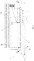
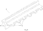
- the first shredding mechanism as portrayed in Figures 2.1, 2.2 , 3 , 4.1 , 4.2 and 6 , comprises a horizontal shaft (7) transversal to the carriage (1) situated in an intermediate position to the first and second surfaces (1, 2) and at a certain height over the second surface (2), where the shaft (7) has a first end (7.1) connected to rotation means, and a second opposite end (7.2).
- this horizontal shaft (7) has longitudinal blades (8) projecting radially from said shaft (7).
- the second surface (2) is positioned horizontally and at a certain height over the first surface (1).
- the bales (5) disposed on the second surface (2) move by means of the second propulsion means towards the first surface (1) and on reaching the end of the second surface (2), the first shredding mechanism acts on the parallelepiped bale (5) breaking it up, for the fodder separated from the bale to later descend to the first surface (1) which is at a lower height than the second surface (2).
- the horizontal shaft (7) of the first shredding mechanism is positioned at a height over the second surface (2) that is the same or appreciably less than the height of a parallelepiped bale (5), to be able to effectively act on said bales and also the device comprises height adjustment means of said horizontal shaft (7) over the second surface (2).
- the shaft (7) since not all the parallelepiped bales (5) have the same height, thanks to these adjustment means (not represented in the Figures) it is possible to place the shaft (7) at the effective height of action on the specific bale (5) that will be acted on, so that they always work in the most effective manner, whatever the bale (5) height.
- the shaft (7) thus disposed at a certain height, as it rotates, performs successive cuts on the parallelepiped bale (5), which descends to the first surface (1) in the form of layers that will end up disintegrating in loose fodder with the dropping itself or due to the movement by the first propulsion mechanism.
- the device comprises a second cylindrical bale shredding mechanism disposed in the end part of the carriage (3), formed by two bale (5) unwinding fins (10) which have a horizontal rotation shaft (11) connected to the first propulsion means, such that the rotation of both is simultaneous.
- the device is suitable for the distribution of both parallelepiped and cylindrical bales (5).
- cylindrical bales they arrive with their cylindrical shape to the first surface (1) in the rear area of the carriage (3) and the first propulsion means generate thereon a movement to the rear part of the carriage (3).
- the outlet opening (4) for the unwound bale is located and its height is precisely defined by the fins (10) of the second shredding mechanism.
- the fins (10) push the cylindrical bale (5) positioned on the first surface (1) forwards, simultaneously to the action of the first propulsion means that continue displacing the bale (5) in the opposite direction, towards the rear part, so that it generates the rotation and unwinding of said bale that exits through the outlet opening (4).
- the first shredding mechanism has at least the second end (7.2) of the horizontal shaft (7) thereof, fastened to the carriage (3) by detachable fastening means.
- the first end (7.1) of the horizontal shaft (7) of the first shredding mechanism is fastened to the carriage (3) by a tilt shaft, such that said horizontal shaft (7) is collapsible with respect to said first end (7.1) to allow the passage of cylindrical bales.
- the cylindrical bales (5) are of greater dimensions than the parallelepiped bales, when it is necessary to load on the carriage (3) bales of said cylindrical shape, the first shredding mechanism is removed by a tilting thereof around the first end (7.1) of the shaft (7), being disposed at one side of the carriage (3) without generating any obstacle for working with cylindrical bales.
- the horizontal shaft (7) of the first shredding mechanism is again placed in its position so that said first mechanism is operational for the shredding of bales.
- the second shredding mechanism aimed at cylindrical bales, does not entail any problem or hindering in the shredding of parallelepiped bales, since they reach the first surface (1) almost broken up in the form of fine bits of fodder, that with the movement itself by means of the first propulsion mechanism exits through the outlet opening (4) of the carriage and is distributed uniformly.
- the two panels (6) for providing additional bale support of this distributor have a horizontal position adjacent to the second surface (2), that configures an additional bale support surface (12). In this way, when the carriage (3) starts its fodder distribution work, it exits the bale loading warehouse with at least one bale on the second surface (2) and at least one bale on both additional surfaces (12) configured by these panels (6) in their horizontal position.
- said panels (6) for providing additional bale support have a first end (6.1) for fastening to one side (2.1) of the second surface (2) of the carriage respectively, such that in their horizontal position they are contained in the plane of said second surface (2).
- Said panels (6) are tilting and the means for moving the bales (5) disposed on one of the additional surfaces (12) to the second surface (2) are formed by a rotation shaft at the first end (6.1) of each panel and tilting actuation means of each panel (6) from the horizontal position thereof to a vertical position that generates the movement of the bales (5) from one of the additional surfaces (12) to the second surface (2).
- the panels (6) for providing additional bale support instead of tilting have other means for moving the bales (5) to the second surface (2) and said moving means may be formed by sliders, for example, that slide said panels (6) towards the second surface (2), generating the movement thereto of the bales (5) supported on the panels, or even be formed by sliders that only slide the bales from the panels (6) to the second surface (2), keeping said panels (6) fixed in their horizontal position adjacent to the second surface (2).
- the fodder distributor further comprises additional bale storage and unloading means formed by a first and second tilting platforms (13, 14) located on the first and second surface (1, 2) respectively, positioned at a height over them higher than the height of the bales disposed on said first and second surfaces (1, 2), where both first and second tilting platforms (13, 14) have tilting means on the second surface (2).
- first and second tilting platforms (13, 14) located on the first and second surface (1, 2) respectively, positioned at a height over them higher than the height of the bales disposed on said first and second surfaces (1, 2), where both first and second tilting platforms (13, 14) have tilting means on the second surface (2).
- the tilting means of each panel (6) comprises a rotation shaft at the first end (6.1) for fastening to one side (2.1) of the second surface (2) and tilting actuation means of said panel (6).
- said tilting actuation means of each panel are formed by a hydraulic cylinder (15), but in other embodiments it may be a pneumatic cylinder or similar means.
- the first and second propulsion means in this preferred embodiment of the invention comprise a first and second worm displacement elements (17.1, 17.2) each one of them connected to a first and second parallel rotation shafts (16.1, 16.2) disposed at the front and rear end according to the direction of travel of the first and the second surface (1, 2) respectively, and transmission means (21) between the second rotation shaft (16.2) of the second worm displacement element (17.2) and the first rotation shaft (16.1) of the first worm displacement element (17.1).
- both the first and the second worm displacement element (17.1, 17.2) are formed by two side chains connected to the corresponding first and second rotation shafts (16.1, 16.2) by respective toothed wheels and, bars (18) perpendicular to said chains, joined thereto such that said bar has a certain separation space with the two bars (18) consecutive thereto.
- the bars (18) of the worm displacement element (17.1) of the first propulsion means have a plurality of sharp elements (19) projecting perpendicularly therefrom.
- These sharp elements (19) in the case of cylindrical bales collaborate in the engagement of the lower part of the bale (5) to achieve its movement to the end part of the first surface (1), shredding it, whilst in the case of parallelepiped bales (5), they reach the first surface (1) already cut into laminar pieces, these sharp elements (19) also collaborate in the movement thereof to the end, breaking them up, on being stuck into them.
- the first and second propulsion means comprise a length (20) of overlapping between both to avoid the loss of fodder therebetween.
- they may be consecutively disposed, without overlapping, but without space between both propulsion means, always with a view to avoiding the existence of a space to lose fodder between both means.
Landscapes
- Life Sciences & Earth Sciences (AREA)
- Environmental Sciences (AREA)
- Birds (AREA)
- Animal Husbandry (AREA)
- Biodiversity & Conservation Biology (AREA)
- Threshing Machine Elements (AREA)
Applications Claiming Priority (2)
| Application Number | Priority Date | Filing Date | Title |
|---|---|---|---|
| ES201903659 | 2019-07-17 | ||
| PCT/ES2020/070411 WO2021009395A1 (fr) | 2019-07-17 | 2020-06-25 | Dispositif distributeur de fourrage |
Publications (2)
| Publication Number | Publication Date |
|---|---|
| EP4000377A1 true EP4000377A1 (fr) | 2022-05-25 |
| EP4000377A4 EP4000377A4 (fr) | 2023-08-09 |
Family
ID=81214549
Family Applications (1)
| Application Number | Title | Priority Date | Filing Date |
|---|---|---|---|
| EP20840927.6A Pending EP4000377A4 (fr) | 2019-07-17 | 2020-06-25 | Dispositif distributeur de fourrage |
Country Status (1)
| Country | Link |
|---|---|
| EP (1) | EP4000377A4 (fr) |
Family Cites Families (7)
| Publication number | Priority date | Publication date | Assignee | Title |
|---|---|---|---|---|
| DE2618942A1 (de) * | 1976-04-29 | 1977-11-17 | Blair Mfg Co | Vorrichtung zum zerteilen von heuballen |
| GB8502214D0 (en) * | 1985-01-29 | 1985-02-27 | Leech D | Straw spreading machine |
| US20030062433A1 (en) * | 1996-10-04 | 2003-04-03 | Hughes Michael John | Bale handling apparatus |
| ES1056934Y (es) * | 2004-02-20 | 2004-09-16 | Parra Del Soberal S A | Dispositivo distribuidor de forraje. |
| NL1026841C2 (nl) * | 2004-08-13 | 2006-02-14 | Trioliet Mullos | Inrichting voor het losmaken en mengen van voer voor vee. |
| ES2550135B1 (es) * | 2014-04-04 | 2016-08-09 | La Parra Del Soberal, S.L.U. | Dispositivo distribuidor de forraje perfeccionado |
| FR3050357B1 (fr) * | 2016-04-20 | 2018-05-11 | Gyrax | Machine agricole de distribution d’un produit tel que du fourrage ou de la litiere et procede de chargement d’une telle machine |
-
2020
- 2020-06-25 EP EP20840927.6A patent/EP4000377A4/fr active Pending
Also Published As
| Publication number | Publication date |
|---|---|
| EP4000377A4 (fr) | 2023-08-09 |
Similar Documents
| Publication | Publication Date | Title |
|---|---|---|
| DE2000553C3 (fr) | ||
| DE2535204C3 (de) | Verfahren und Vorrichtung zur Verarbeitung von Viehfutter | |
| DE2729012C2 (de) | Mähdrescher der Axialflußbauart | |
| EP0131549A2 (fr) | Dispositif de manutention de balles et de distribution de foin | |
| DE69010150T2 (de) | Vorrichtung zum Zerkleinern von Silageblöcken. | |
| US9669370B2 (en) | Animal feed mixing and dispensing apparatus | |
| US7871029B2 (en) | Bale processor having improved shredding roller | |
| DE2301977C3 (de) | Vorrichtung zum schrittweisen dosierbaren Abbau eines Haufwerkes | |
| DE3224446A1 (de) | Vorrichtung zum foerdern, handhaben und rueckfoerdern von schuettgut | |
| EP3308623A1 (fr) | Moissonneuse-batteuse pourvue de rampe de chargement pour paille et élévateur pour paille | |
| CA3143589C (fr) | Dispositif distributeur de fourrage | |
| EP0102406A1 (fr) | Chariot pour la réception et la distribution de silage, de paille et de produits similaires | |
| EP1050206B1 (fr) | Récolteuse | |
| DE2810676A1 (de) | Dosiervorrichtung fuer landwirtschaftliche erntegueter | |
| DE2143532C2 (de) | Dreschgutzuführung bei einem Mähdrescher der Axialflußbauart | |
| EP3127418B1 (fr) | Dispositif distributeur de fourrage perfectionné | |
| US3530912A (en) | Bale shredder and discharger | |
| DE1482851A1 (de) | Maiserntemaschine | |
| EP2659763A1 (fr) | Machine de récolte dotée d'un dispositif de coupe | |
| DE3535155A1 (de) | Foerder- und schneidaggregat fuer ladewagen | |
| US1501455A (en) | Thrashing machine and parts thereof | |
| JP5027420B2 (ja) | 堆肥ヤード造成装置 | |
| DE60100702T2 (de) | Kompostmietenumsetzer | |
| DE19745764C2 (de) | Vorrichtung zur Verteilung von Erntegut | |
| WO2005079556A1 (fr) | Dispositif distributeur de fourrage |
Legal Events
| Date | Code | Title | Description |
|---|---|---|---|
| STAA | Information on the status of an ep patent application or granted ep patent |
Free format text: STATUS: THE INTERNATIONAL PUBLICATION HAS BEEN MADE |
|
| PUAI | Public reference made under article 153(3) epc to a published international application that has entered the european phase |
Free format text: ORIGINAL CODE: 0009012 |
|
| STAA | Information on the status of an ep patent application or granted ep patent |
Free format text: STATUS: REQUEST FOR EXAMINATION WAS MADE |
|
| 17P | Request for examination filed |
Effective date: 20220204 |
|
| AK | Designated contracting states |
Kind code of ref document: A1 Designated state(s): AL AT BE BG CH CY CZ DE DK EE ES FI FR GB GR HR HU IE IS IT LI LT LU LV MC MK MT NL NO PL PT RO RS SE SI SK SM TR |
|
| DAV | Request for validation of the european patent (deleted) | ||
| DAX | Request for extension of the european patent (deleted) | ||
| P01 | Opt-out of the competence of the unified patent court (upc) registered |
Effective date: 20230510 |
|
| A4 | Supplementary search report drawn up and despatched |
Effective date: 20230710 |
|
| RIC1 | Information provided on ipc code assigned before grant |
Ipc: A01D 90/10 20060101ALI20230704BHEP Ipc: A01D 87/12 20060101AFI20230704BHEP |
|
| STAA | Information on the status of an ep patent application or granted ep patent |
Free format text: STATUS: EXAMINATION IS IN PROGRESS |
|
| 17Q | First examination report despatched |
Effective date: 20250304 |