EP4000435B1 - Elektronische verdampfungsvorrichtung und raucherzeugungsanordnung - Google Patents
Elektronische verdampfungsvorrichtung und raucherzeugungsanordnung Download PDFInfo
- Publication number
- EP4000435B1 EP4000435B1 EP20844373.9A EP20844373A EP4000435B1 EP 4000435 B1 EP4000435 B1 EP 4000435B1 EP 20844373 A EP20844373 A EP 20844373A EP 4000435 B1 EP4000435 B1 EP 4000435B1
- Authority
- EP
- European Patent Office
- Prior art keywords
- unit
- air
- baking
- smoke
- spiral
- Prior art date
- Legal status (The legal status is an assumption and is not a legal conclusion. Google has not performed a legal analysis and makes no representation as to the accuracy of the status listed.)
- Active
Links
Images







Classifications
-
- A—HUMAN NECESSITIES
- A24—TOBACCO; CIGARS; CIGARETTES; SIMULATED SMOKING DEVICES; SMOKERS' REQUISITES
- A24F—SMOKERS' REQUISITES; MATCH BOXES; SIMULATED SMOKING DEVICES
- A24F40/00—Electrically operated smoking devices; Component parts thereof; Manufacture thereof; Maintenance or testing thereof; Charging means specially adapted therefor
- A24F40/10—Devices using liquid inhalable precursors
-
- A—HUMAN NECESSITIES
- A24—TOBACCO; CIGARS; CIGARETTES; SIMULATED SMOKING DEVICES; SMOKERS' REQUISITES
- A24F—SMOKERS' REQUISITES; MATCH BOXES; SIMULATED SMOKING DEVICES
- A24F40/00—Electrically operated smoking devices; Component parts thereof; Manufacture thereof; Maintenance or testing thereof; Charging means specially adapted therefor
- A24F40/20—Devices using solid inhalable precursors
-
- A—HUMAN NECESSITIES
- A24—TOBACCO; CIGARS; CIGARETTES; SIMULATED SMOKING DEVICES; SMOKERS' REQUISITES
- A24F—SMOKERS' REQUISITES; MATCH BOXES; SIMULATED SMOKING DEVICES
- A24F40/00—Electrically operated smoking devices; Component parts thereof; Manufacture thereof; Maintenance or testing thereof; Charging means specially adapted therefor
- A24F40/40—Constructional details, e.g. connection of cartridges and battery parts
- A24F40/48—Fluid transfer means, e.g. pumps
- A24F40/485—Valves; Apertures
-
- A—HUMAN NECESSITIES
- A24—TOBACCO; CIGARS; CIGARETTES; SIMULATED SMOKING DEVICES; SMOKERS' REQUISITES
- A24F—SMOKERS' REQUISITES; MATCH BOXES; SIMULATED SMOKING DEVICES
- A24F40/00—Electrically operated smoking devices; Component parts thereof; Manufacture thereof; Maintenance or testing thereof; Charging means specially adapted therefor
- A24F40/30—Devices using two or more structurally separated inhalable precursors, e.g. using two liquid precursors in two cartridges
Definitions
- the described embodiments relate to the field of atomizers, and in particular, to an electronic atomization device and a smoke-generating assembly.
- the present invention relates to a smoke-generating assembly for an electronic cigarette.
- Traditional smoking ignites a tobacco via an open fire, and the tobacco is burned to produce smoke for a smoker to inhale.
- the smoke produced by burning the tobacco generally includes thousands of harmful substances. Therefore, traditional tobacco not only causes serious respiratory diseases to the smoker, but also easily brings harm from second-hand smoke.
- FIG. CN108185537A discloses an aerosol generating device, comprising an outer housing (1) and a built-in power supply (3) and a control circuit board (2); the outer housing (1) is provided with a jack (13), a stationary cartridge (7) for accommodating aerosol generating product is provided under the jack (13), the stationary cartridge (7) is disposed with a conductive member and a heating member, and the conductive member includes at least two power poles (8) disposed on a side wall of the stationary cartridge (7); and an aerosol generating product, comprising a suction nozzle (33) disposed at one end thereof and a peripheral tubular housing (34); at least two circular electrodes (35) (36) are disposed on a side wall of the tubular housing (34), and the circular electrodes (35) (36) fit to the power poles (8) of the aerosol generating device.
- Document WO2018112769A1 discloses an atomizer.
- An oil storage chamber (103), an atomization chamber (104) and a heating component (105) are provided in an atomizer body (100).
- a receiving chamber (200) is provided in a suction nozzle component (101).
- Smoke formed by atomization in the atomization chamber (104) is used to heat tobacco (201) in the receiving chamber (200) to generate mixed smoke so that during smoking, smoke flows from the atomization chamber (104) to the receiving chamber (200), and heats the tobacco (201) in the receiving chamber (200) to enable the tobacco (201) to give off fragrance through baking.
- a large amount of smoke can be generated, avoiding harmful substances due to carbonization easily occurred when the tobacco (201) is baked with an electrical heating device.
- a second smoke channel (501) is provided in the suction nozzle component (101), so as to ensure that at least part of the smoke atomized by the heating component (105) can be conducted to a smoke outlet (102), even if the tobacco (201) contains considerable water as the time of using the atomizer increases.
- atomized electronic cigarettes and electronic flue-cured cigarettes have been developed by technicians.
- the atomized electronic cigarettes overcome the above disadvantages of traditional cigarettes and can meet consumers' dependence on the tobacco to a certain extent, the cigarette liquid of the electronic cigarettes is made of flavors and fragrances, and is not a real cigarette product. In this way, the cigarette tastes light and lacks aroma of the tobacco, therefore, the atomized electronic cigarettes cannot be widely accepted by consumers.
- Existing low-temperature electronic flue-cured cigarettes heats the tobacco in a low-temperature manner where the solid smoking medium is non-combustion.
- a baking unit is also configured to bake a solid smoking medium to solve the above problems.
- the solid smoking medium is generally directly arranged on a baking cavity, and atomized gas is passed into the solid smoking medium.
- it has the following shortcoming: average flow velocity is low, flow velocities are uneven, amount of nicotine released is small, and consumption of the solid smoking medium is great.
- the technical problem to be solved by the present disclosure is to provide an improved electronic atomization device, and further to provide an improved smoke-generating assembly.
- the electronic atomization device and the smoke-generating assembly of the present invention have the following beneficial effects: the electronic atomization device is arranged with the smoke-generating assembly arranged on the baking unit, and the flow perturbation member of the smoke-generating assembly is embedded in the solid smoking medium, such that an average air flow velocity is increased with the flow perturbation member perturbing, and the velocity uniformity is also improved, thereby making air flow have an adequate contact with the tobacco leaves, and a convective heat transfer and release and transmission of active ingredients in the solid smoking medium are improved.
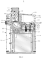
- FIGS. 1 to 2 show some embodiments of an electronic atomization device 1 of the present disclosure.
- the electronic atomization device 1 may include a housing 10, an atomization unit 20, a baking unit 80, a smoke-generating assembly 40, a power unit 50, an air switch unit 60, a main control unit 70, and a communication unit 30.
- the atomization unit 20, the baking unit 80, the smoke-generating assembly 40, the power unit 50, the air switch unit 60, the main control unit 70, and the communication unit 30 may be arranged in the housing 10.
- the atomization unit 20 is configured to atomize liquid medium, such as cigarette liquid, and the like. In some embodiments, it should be appreciated that the atomization unit 20 may be omitted.
- the baking unit 80 may bake the smoke-generating assembly 40 to form smoke for a user to inhale.
- the baking unit 80 is configured to heat a solid smoking medium, such as the smoke-generating assembly 40 (flavor bomb), to form the smoke.
- the atomization unit 20 and the baking unit 80 are arranged side by side on an upper part of the housing 10. More specifically, the atomization unit 20 and the baking unit 80 are arranged horizontally side by side along a first direction in the upper part of the housing 10.
- the smoke-generating assembly 40 is arranged on the baking unit 80, and is configured to generate the smoke for the user to inhale when the smoke-generating assembly 40 is baked by the baking unit 80.
- the power unit 50 is configured to power the atomization unit 20 and the baking unit 80 and arranged on a lower part of the housing 10. Specifically, the power unit 50, the atomization unit 20, and the baking unit 80 are arranged longitudinally inside the housing 10 along a second direction shown in FIG. 1 .
- the first direction is a direction substantially parallel to an X-axis (as shown in FIG. 1 ).
- the second direction is a direction substantially parallel to a Y-axis (as shown in FIG. 1 ) and perpendicular to the X-axis.
- the air switch unit 60 is arranged between the baking unit 80 and the power unit 50.
- the air switch unit 60 is configured to, when driven by an air, control connecting or disconnecting between the power unit 50 and the atomization unit 20 or between the power unit 50 and the baking unit 80.
- the main control unit 70 is arranged on a side portion of the housing 10, and configured to achieve unlocking, data inputting, controlling, and other functions of the electronic atomization device 1.
- the communication unit 30 is arranged on a lower part of the baking unit 80, and configured to fluidly communicate the baking unit 80 to the atomization unit 20, so that it is possible that the smoke and an atomizing air are exhausted after the smoke and an atomizing air being mixed with each other, thereby satisfying the user demand.
- the atomization unit 20 is detachably arranged in the housing 10, so as to achieve exchange of the atomization unit 20.
- the power unit 50 includes a battery.
- the housing 10 may be substantially longitudinal flat.
- the housing 10 may include a sleeve 11, a support 13 arranged on the sleeve 11, and a nozzle 15 arranged on a top of the support 13.
- the sleeve 11 may be substantially longitudinal flat, and is sleeved on a periphery of the support 13.
- the support 13 is configured for an installation of the atomization unit 20, the power unit 50, the main control unit 70, and the communication unit 30.
- the nozzle 15 may be substantially cylindrical, and is configured to the user inhaling the smoke.
- the support 13, the sleeve 11, and the nozzle 15 are integrally formed.
- the support 13 may include a first accommodating space 131 configured to accommodate the atomization unit 20, a second accommodating space 132 configured to accommodate the baking unit 80, a third accommodating space 133 configured to accommodate the power unit 50, a fourth accommodating space 134 configured to accommodate the air switch unit 60, a fifth accommodating space 135 configured to accommodate the main control unit 70, and a sixth accommodating space 136 configured to accommodate the communication unit 30.
- a partition wall 137 is defined between the first accommodating space 131 and the third accommodating space 133, and configured to separate the first accommodating space 131 from the third accommodating space 133.
- a top of the partition wall 137 defines a pair of electrode pores 1371, a pair of accommodating holes 1372 configured to receive magnetically attractive elements, and a first arcuate gas-guide groove 1373.
- the pair of electrode pores 1371 are distributed and spaced apart from each other along a length direction of the partition wall 137.
- the first arcuate gas-guide groove 1373 may include a first end away from the third accommodating space 133 and a second end close to the third accommodating space 133, and the first arcuate gas-guide groove 1373 extends from the first end towards the second end.
- the third accommodating space 133 is located in a distal end of the support 13 away from the nozzle 15.
- the first accommodating space 131 and the second accommodating space 132 are located in a proximal end of the support 13 close to the nozzle 15. Accordingly, the power unit 50 is located in the distal end far away from the nozzle 15, and the atomization unit 20 and the baking unit 80 are located in the proximal end close to the nozzle 15. In this way, it is possible to make a structure of the electronic atomization device 1 more compact.
- the partition wall 137 further includes a second gas-guide groove 1374, which is in communication with or fluidly communicated to the second end of the first arcuate gas-guide groove 1373 sunk or recessed downwardly and longitudinally, and a horizontal third gas-guide groove 1375, which is configured to fluidly communicate the second gas-guide groove 1374 to the third accommodating space 133, thereby forming a first air flow channel fluidly communicated to the air switch unit 60.
- the first gas-guide groove 1373 has an arcuate shape, so that it is possible that a rate of a leakage inflowing the air switch unit 60 is decreased to a certain extent, thereby preventing the leakage from having an adverse effect on the air switch unit 60.
- a bottom of the second gas-guide groove 1374 is located at a level lower than a connecting end of the third gas-guide groove 1375 and the second gas-guide groove 1374. In this way, even if the leakage inflows the air switch unit 60, a lower portion of the second gas-guide groove 1374 may accommodate a part of the leakage, thereby further decreasing a possibility of the leakage inflowing the air switch unit 60.
- the housing 10 further includes a pair of electrode contacts 12, a pair of magnetic attraction members 14, and a sealing cap 17.
- the electrode contacts 12 is inserted through the electrode pores 1371 and electrically connected to the power unit 50.
- the magnetic attraction members 14 are embedded in the accommodating holes 1372, so as to attract the atomization unit 20.
- the sealing cap 17 is configured to cap a top of the partition wall 137, so as to seal the first gas-guide groove 1373.
- the sealing cap 17 further defines an opening (not shown) configured to expose the electrode contacts 12 and the magnetic attraction members 14.
- a vent hole 170 is defined on the sealing cap 17, and is fluidly communicated to the first end of the first gas-guide groove 1373.
- the vent hole 170 is configured to fluidly communicate the first air channel to a gas-guide hole 212 of the atomization unit 20.
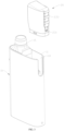
- the atomization unit 20 may include a base 21, an atomization assembly 22 arranged on the base 21, an atomization shell 23 sleeved on the base 21, and a pair of electrodes 24 electrically connected to the atomization assembly 22.
- the atomization shell 23 defines a liquid storage cavity 230 configured to accommodate the liquid medium.
- a top liquid suction surface of the atomization assembly 22 is exposed in the liquid storage cavity 230, and is configured to connect the liquid storage cavity 230 in a liquid conducting manner.
- the atomization assembly 22 may include a porous body and a heating element arranged on the porous body. The heating element is configured to electrically connect the electrodes 24 via a conductive connection part.
- the base 21 includes a second air flow channel 210 arranged horizontally, and the second air flow channel 210 is located below the atomization assembly 22. In addition, a bottom atomizing surface of the atomization assembly 22 is exposed in the second air flow channel 210.
- Two opposite sides of the atomization shell 23, that is, an outer side and an inner side of the atomization shell 23, further define a first air inlet 231 and a first air outlet 232, and the first air inlet 231 and the first air outlet 232 are fluidly communicated to the second air flow channel 210, that is to say, the second air flow channel 210 is provided with two sides, one side of the second air flow channel 210 is fluidly communicated to the first air inlet 231, and another side of the second air flow channel 210 is fluidly communicated to the first air outlet 232.
- the first air inlet 231 is located a side of the atomization unit 20 away from the baking unit 80, such that outside air is able to enter the second air flow channel 210 and mixed with the atomizing air produced by the atomization assembly 22.
- the first air outlet 232 is located a side of the atomization unit 20 close to the baking unit 80, such that a mixed air flows out of the atomization unit 20 via the first air outlet 232.
- the outer side of the atomization shell 23 is arranged with a plurality of convex pushing portions 233, thereby facilitating pushing the atomization unit 20 out of the housing 10. Accordingly, the sleeve 11 of the housing 10 defines a recess 110, and the recess 110 is configured to expose the pushing portions 233.
- the base 21 further includes a gas-guide hole 212, one end of the gas-guide hole 212 is fluidly communicated to an end of the second air flow channel 210 close to the first air inlet 231. Another end of the gas-guide hole 212 extends downward a bottom of the base 21, and is configured to be fluidly communicated to the first air flow channel of the support 13.
- the pair of electrodes 24 is inserted from the bottom of the base 21, electrically connected to the electrode contacts 12, and further electrically connected to the conductive connection part of the heating element of the atomization assembly 22.
- the baking unit 80 is cylindrical and arranged longitudinally in the housing 10. In addition, a lower portion of the baking unit 80 is connected to the communication unit 30, and an upper portion of the baking unit 80 is connected to the nozzle 15.
- the baking unit 80 may include a cylindrical heating element and a cylindrical heat conductor coaxially arranged on an inner side of the heating element. The inner side of the heating element form a baking cavity configured to accommodate the smoke-generating assembly 40.
- the baking cavity defines a second air inlet arranged on a bottom and a second air outlet arranged on a top, and the second air inlet is fluidly communicated to the communication channel 33.
- the cylindrical heat conductor is arranged on an end of the second air outlet of the baking cavity , and is made of metallic material with high heat conductivity such as copper, aluminium, stainless steel, or the like.
- the baking unit 80 is configured to heat the solid smoking medium, such as a tobacco, in a low-temperature manner where the solid smoking medium is non-combustion. In this way, due to a low heating temperature, harmful substances produced by means of heating are reduced.
- a heating temperature of the baking unit 80 is configured to keep an inner temperature of the solid smoking medium be 40 to 50 degrees Celsius. In some embodiments, the heating temperature of the baking unit 80 may be 45 to 55 degrees Celsius.
- the communication unit 30 may include a front half part 31 and a rear half part 32 spliced with the front half part 31.
- a surface of the front half part 31 facing the rear half part 32 defines a first arcuate groove 310, and a cross-section of the first arcuate groove 310 is in shape of a semicircle.
- a surface of the rear half part 32 facing the front half part 31 defines a second arcuate groove 320, and a cross-section of the second arcuate groove 320 is in shape of a semicircle.
- a top of the rear half part 32 further defines a third air outlet 322 fluidly communicated to an upper portion of the second arcuate groove 320.
- a side of the rear half part 32 adjacent to the atomization unit 20 defines a third air inlet 321 fluidly communicated to a lower portion of the second arcuate groove 320.
- the communication channel 33 is configured to fluidly communicate the second air flow channel 210 of the atomization unit 20 arranged horizontally to the baking cavity of the baking unit 80 arranged longitudinally.
- One end of the communication channel 33 is fluidly communicated to the first air outlet 232, and another end of the communication channel 33 is fluidly communicated to the second air inlet.
- the top of the rear half part 32 further defines a round groove 323, and the round groove 323 is closely sleeved on a bottom of the baking unit 80, so that the communication channel 33 is in a close communication with the baking cavity of the baking unit 80.
- the smoke-generating assembly 40 may be accommodated in the baking cavity and detachably attached to the baking cavity.
- the smoke-generating assembly 40 may include the solid smoking medium, a flow perturbation member 41, and an accommodating device 42.
- the solid smoking medium may include tobacco particles or tobacco leaves, and is configured to produce the smoke for the user to inhale in the low-temperature and non-combustion manner.
- the solid smoking medium may be columnar.
- the flow perturbation member 41 may be embedded in the solid smoking medium and arranged longitudinally in the solid smoking medium, such that an average air flow velocity is increased with the perturbing of the flow perturbation member 41, and the velocity uniformity is also improved, thereby making air flow have a sufficient contact with the tobacco leaves, and a convective heat transfer and release and transmission of nicotine are improved.
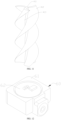
- the flow perturbation member 41 may be spiral, and extend longitudinally in the solid smoking medium. Furthermore, the flow perturbation member 41 may include a central cylinder 411 and three flow perturbation pieces 412 arranged at intervals.
- the central cylinder 411 is integrally formed with the flow perturbation pieces 412. In some embodiments, the central cylinder 411 may be omitted.
- the number of the flow perturbation pieces 412 may be one or a plurality, and is not limited to three.
- the three flow perturbation pieces 412 may be arranged at intervals along an outer circumferential wall of in the central cylinder 411 in a circumferential direction, each of the three flow perturbation pieces 412 extends along an axial direction of the central cylinder 411.
- each of the flow perturbation pieces 412 may be spiral, and defines a spiral air flow channel 413 having a spiral shape.
- the spiral air flow channel 413 may be arranged between two adjacent flow perturbation pieces 412, and is configured to allow or enable the air to enter the solid smoking medium. Further, the spiral air flow channel 413 may extend longitudinally and be fluidly communicated to the second air flow channel 210. With the spiral air flow channel 413 being arranged spirally, paths of the air are increased or extended, thereby improving the velocity uniformity. In addition, it is possible to increase a contact area of the solid smoking medium contacting with the air, so that the air flow passing through the solid smoking medium may more sufficiently contact with the solid smoking medium, thereby improving the release and the transmission of the nicotine.
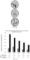
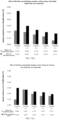
- an average flow velocity of a longitudinal section is 0.503m/s.
- the average flow velocity of the longitudinal section is 0.573m/s, such that the average velocity of the longitudinal section is increased by 13.9%.
- average flow velocities of horizontal sections of sections of the solid smoking medium arranged sequentially along an air flow direction are 0.456m/s, 0.439m/s, and 0.395m/s, respectively.
- the average flow velocities of the horizontal sections of sections of the solid smoking medium arranged sequentially along the air flow direction are 0.539m/s, 0.539m/s, and 0.559m/s, respectively, such that the average velocities of the horizontal sections are increased by 21.5%.
- the flow perturbation member 41 can effectively improve the release of the nicotine in raw materials. After adding the flow perturbation member 41, the less the raw materials, the more nicotine is released, and the improvement effect is more obvious. More specifically, by arranging with the flow perturbation member 41, it is possible to make the air flow have sufficient contact with the solid smoking medium, thereby improving a release amount of the nicotine, such that an amount of the raw materials in the solid smoking medium is reduced by two thirds (2/3), and the cost can be greatly reduced.
- the accommodating device 42 may be cylindrical and configured to accommodate the solid smoking medium.
- the accommodating device 42 may be a metal sleeve with high heat conductivity. A bottom of the sleeve may define an air inlet, so that the sleeve may be fluidly communicated to the second air flow channel 210, and the air may be allowed or enabled to enter.
- the accommodating device 42 may be a wrapping paper wrapped around the solid smoking medium, and is not limited to the sleeve.
- the smoke-generating assembly 40 further includes an installation sleeve 43 arranged in the accommodating device 42 and located in an end close to the nozzle 15, and a filter cotton 44 arranged in the installation sleeve 43.
- the installation sleeve 43 may be omitted.
- the filter cotton 44 is received in the accommodating device 42, and located in an end of the accommodating device 42 close to the nozzle 15.
- the filter cotton 44 may be columnar, and configured to filtrate the smoke produced by the solid smoking medium.
- the air switch unit 60 may include an installation base 61, and an air switch 62 installed in the installation base 61.
- the installation base 61 includes or defines an accommodating cavity 610, and the accommodating cavity 610 defines a top opening at a top.
- the air switch 62 is arranged upside down in the top opening, and a gap is defined between a triggering surface at a top of the air switch 62 and a cavity bottom of the accommodating cavity 610.
- the installation base 61 further includes a communication conduit 612 configured to fluidly communicate the gap to an outer side.
- the communication conduit 612 is configured to be fluidly communicated to the second air flow channel 210 of the housing 10.
- the triggering surface of the air switch 62 may be fluidly communicated to the second air flow channel 210 of the atomization unit 20 via the first air flow channel. Furthermore, in response to an air being inhaled in the second air flow channel 210, a negative pressure is formed in the first air flow channel, such that a negative pressure is formed in the triggering surface of the air switch 62, and the air switch 62 is caused to be in a conducting state.
- the accommodating cavity 610 is not easy to contact with the triggering surface of the air switch 62 even if the leakage inflows the air switch unit 60, thereby further ensuring a normal operation of the air switch 62.
Landscapes
- Electrostatic Spraying Apparatus (AREA)
- Manufacture Of Tobacco Products (AREA)
Claims (14)
- Eine Raucherzeugungsbaugruppe (40) für eine elektronische Zigarette, wobei die Raucherzeugungsbaugruppe (40 Folgendes umfasst:Ein solides Rauchmittel undein durchflussstörendes Element (41), das im soliden Rauchmittel eingebettet ist;dadurch gekennzeichnet, dassdas durchflussstörende Element (41) mindestens einen spiralförmigen Luftstromkanal (413) definiert und der mindestens eine spiralförmige Luftstromkanal (413) sich der Länge nach erstreckt.
- Die Raucherzeugungsbaugruppe (40) gemäss Anspruch 1, bei der das durchflussstörende Element (41) spiralförmig ist und sich der Länge nach im soliden Rauchmittel erstreckt; das solide Rauchmittel Tabakblätter oder Tabakteilchen umfasst, und in dem mindestens einen spiralförmigen Luftstromkanal (413) angeordnet ist.
- Eine elektronische Zerstäubungsvorrichtung (1), die Folgendes umfasst:Eine Brenneinheit (80), die einen Brennhohlraum definiert; unddie Rauchentwicklungsbaugruppe (40) gemäss Anspruch 1, die im Brennhohlraum aufgenommen ist.
- Die elektronische Zerstäubungsvorrichtung (1) gemäss Anspruch 3, bei der das durchflossstörende Element (41) spiralförmig ist, mindestens einen spiralförmigen Luftstromkanal (413) definiert und sich in Längsrichtung im soliden Rauchmittel erstreckt, wobei die elektronische Zerstäubungsvorrichtung (1) weiter eine Zerstäubungseinheit (20) umfasst, und die Zerstäubungseinheit (20) einen ersten Lufteinlass (231) definiert, der in Fluidverbindung mit der Aussenluft kommuniziert, die Aussenluft durch den ersten Lufteinlass (231) durch die Zerstäubungseinheit (20) und den mindestens einen spiralförmigen Luftstromkanal (413) einlass und mit dem soliden Rauchmittel in Kontakt kommt; das solide Rauchmittel an dem mindestens einen spiralförmigen Luftstromkanal (413) angeordnetist.
- Die elektronische Zerstäubungsvorrichtung (1) gemäss Anspruch 4, bei der die Zerstäubungseinheit (20) in Fluidverbingung mit dem ersten Lufteinlass (231) und dem Brennhohlraum kommuniziert, und die Aussenluft ab dem ersten Lufteinlass (231) einlass, durch die Zerstäubungseinheit (20) fliesst, in den mindestens einen spiralförmigen Luftstromkanal (413) einlass und mit dem soliden Rauchmittel kontaktiert.
- Die elektronische Zerstäubungsvorrichtung (1) gemäss irgendeinem der Ansprüche 3 bis 5, bei der das durchflussstörende Element (41) mindestens einen durchflussstörendes Teil umfasst, das spiralförmig angeordnet ist, und das mindestens eine durchflussstörende Stück (412) den mindestens einen spiralförmigen Luftstromkanal (413) definiert.
- Die elektronische Zerstäubungsvorrichtung (1) gemäss irgendeinem der Ansprüche 3 bis 5, bei der das durchflussstörende Element (41) eine Vielzahl von spiralförmigen, durchflussstörenden Teilen (412) umfasst, die untereinander beabstandet und miteinander eingebettet sind, und wobei ein spiralförmiger Durchflusskanal (413) zwischen allen zwei anliegenden durchflussstörenden Teilen (412) definiert ist.
- Die elektronische Zerstäubungsvorrichtung (1) gemäss Anspruch 7, bei der das drchflussstörende Element (41) einen zentalen Zylinder (411) umfasst, die Vielzahl von spiralförmigen, durchflussstörenden Teilen (412) in Abständen längs einer Aussenumfangswand des zentralen Zylinders (411) in Umfangsrichtung angeordnet sind, und jeder der durchflussstöarenden Teile (412) sich längs in Axialrichtung des zentralen Zylinders (411) erstreckt.
- Die elektronische Zerstäubungsvorrichtung (1) gemäss irgendeinem der Ansprüche 3 bis 8, bei der die Raucherzeugungsbaugruppe (40) ablösbar im Brennohlraum angeordnet ist und wobei die Raucherzeugungsbaugruppe (40) weiter eine Aufnahmeeinrichtung (42) umfasst, die konfiguriert ist, um das solide Rauchmittel aufzunehmen.
- Die elektronische Zerstäubungsvorrichtung (1) gemäss Amspruch 5, wobei die elektronische Zerstäubungsvorrichtung (1) weiter ein Gehäuse (10) umfasst, die Zerstäubugseinheit (20) und die Brenneinheit (80) horizontal Seite bei Seite im Gehäuse (10) angeordnet sind;wobei die Zerstäubungseinheit (20) einen Luftdurchflusskanal (210) umfasst, der längs in der Zerstäbungseinheit (20) angeordnet ist, der Luftdurchflusskanal (210) den ersten Lufteinlass (231) und einen ersten Luftauslass (232) umfasst, wobei der erste Luftauslass (232) in einer Seite der Zerstäubungseinheit (20) nahe der Brenneinheit (80) lokalisiert ist, und der erste Lufteinlass (231) in einer Seite der Zerstäubungseinheit (20) entfernt von der Brenneinheit (80) lokalisiert ist; undder Brennhohlraum längs in der Brenneinheit (80) definiert ist und einen zweiten Lufteinlass und einen zweiten Luftauslass umfasst, wobei der zweite Lufteinlass in Fluidverbindung mit dem zweiten Luftauslass verbunden ist.
- Die elektronische Zerstäubungsvorrichtung (1) gemäss Anspruch 10, wobei die elektronische Zerstäubungsvorrichtung (1) weiter eine Kommunikationseinheit (30) umfasst, und die Kommunikationseinheit (30) einen Kommunikationskanal (33), einen dritten, an einem oberen Ende lokalisierten Luftauslass (322) und einen dritten, an einer horizontalen Oberfläche nahe einer Seite der Zerstäubungseinheit (20) lokalisierten Lufteinlass (321) umfasst;wobei der Kommunikationskanal (33) konfiguriert ist, um in Fluidverbindung den ersten Luftauslass (232) der Zerstäubungseinheit (20) mit dem Brennhohlraum zu kommunizieren; undwobei der dritten Lufteinlass (321) in Fluidverbindung mit dem ersten Luftauslass (232) kommuniziert und der dritte Luftauslass (322) in Fluidverbindung mit dem zweiten Lufteinlass kommuniziert.
- Die elektronische Zerstäubungsvorrichtung (1) gemäss Anspruch 11, bei der das Gehäuse (10) eine Düse (15) umfasst, die Brenneinheit (80) zylinderförmig und längs im Gehäuse (10) angeordnet ist, ein unterer Teil der Brenneinheit mit der Kommunikationseinheit (30) verbunden ist und ein oberer Teil der Brenneinheit (80) mit der Düse (15) verbunden ist.
- Die elektronische Zerstäubungsvorrichtung (1) gemäss Anspruch 11 oder 12, bei der die Kommunikationseinheit (30) eine vordere Hälfte (31) und eine hintere, mit der vorderen Hälfte (31) gespleisste hintere Hälfte (32) umfasst, wobei eine Oberfläche der vorderen Hälfte (31), die zur hinteren Hälfte (32) gerichtet ist, eine erste gebogene Rille (310) definiert, und ein Querschnitt der ersten gebogenen Rille (310) die Form eines Halbkreises aufweist;wobei eine Oberfläche der hinteren Hälfte (32), die zur vorderen Hälfte (31) gerichtet ist, eine zweite gebogene Rille (320) definiert und ein Querschnitt der zweiten gebogenen Rille (320) die Form eines Halbkreises aufweist;wobei der dritte Luftauslass (322) in Fluidverbindung mit einem oberen Teil der zweiten gebogenen Rille (320) kommuniziert und der dritte Lufteinlass ( 321) in Fluidverbindung mit einem unteren Teil der zweiten gebogenen Rille (320) kommuniziert;wobei, nachdem die vordere Hälfte (31) mit der hinteren Hälfte (32) gespleisst wurde, die erste gebogene Rille (310) und die zweite gebogene Rille (320) kooperierend den Kommunikationskanal (33) in Form eines Bogens definieren.
- Die elektronische Zerstäubungsvorrichtung (1) gemäss Anspruch 13, bei der der obere Teil der hinteren Hälfte (32) weiter eine Rille (323) definiert, Rille (323), die über einen Boden der Brenneinheit (80) aufgeschoben ist, und wobei der Kommunikationskanal (33) in Fluidverbindung mit dem Brennhohlraum kommuniziert.
Applications Claiming Priority (2)
| Application Number | Priority Date | Filing Date | Title |
|---|---|---|---|
| CN201910663302.XA CN110338467B (zh) | 2019-07-22 | 2019-07-22 | 一种电子雾化装置及发烟组件 |
| PCT/CN2020/098600 WO2021012882A1 (zh) | 2019-07-22 | 2020-06-28 | 一种电子雾化装置及发烟组件 |
Publications (3)
| Publication Number | Publication Date |
|---|---|
| EP4000435A1 EP4000435A1 (de) | 2022-05-25 |
| EP4000435A4 EP4000435A4 (de) | 2022-09-14 |
| EP4000435B1 true EP4000435B1 (de) | 2024-08-14 |
Family
ID=68179743
Family Applications (1)
| Application Number | Title | Priority Date | Filing Date |
|---|---|---|---|
| EP20844373.9A Active EP4000435B1 (de) | 2019-07-22 | 2020-06-28 | Elektronische verdampfungsvorrichtung und raucherzeugungsanordnung |
Country Status (4)
| Country | Link |
|---|---|
| US (1) | US12250968B2 (de) |
| EP (1) | EP4000435B1 (de) |
| CN (1) | CN110338467B (de) |
| WO (1) | WO2021012882A1 (de) |
Families Citing this family (8)
| Publication number | Priority date | Publication date | Assignee | Title |
|---|---|---|---|---|
| CN210538906U (zh) * | 2019-05-14 | 2020-05-19 | 深圳麦克韦尔科技有限公司 | 电子雾化装置 |
| CN110338467B (zh) | 2019-07-22 | 2025-03-04 | 深圳麦克韦尔科技有限公司 | 一种电子雾化装置及发烟组件 |
| CN111011932B (zh) * | 2019-12-26 | 2025-03-21 | 深圳麦克韦尔科技有限公司 | 电子雾化装置及其雾化器 |
| CN111920106B (zh) * | 2020-09-05 | 2021-06-08 | 深圳市劳斯韦伯科技有限公司 | 旋流电子烟雾化器结构及其旋流电子烟雾化器 |
| CN113907426B (zh) * | 2021-09-28 | 2023-10-27 | 深圳市真味生物科技有限公司 | 电子雾化装置 |
| WO2023065152A1 (zh) * | 2021-10-20 | 2023-04-27 | 深圳麦克韦尔科技有限公司 | 雾化装置 |
| EP4329528A4 (de) * | 2022-06-17 | 2024-10-02 | KT&G Corporation | Aerosolerzeugungsvorrichtung mit einem verdampfer |
| JP7698132B2 (ja) * | 2022-06-29 | 2025-06-24 | ケーティー アンド ジー コーポレイション | エアロゾル生成装置 |
Family Cites Families (27)
| Publication number | Priority date | Publication date | Assignee | Title |
|---|---|---|---|---|
| US2533956A (en) * | 1946-08-07 | 1950-12-12 | Robertson Thayne | Stoker smoking pipe |
| CA2807635C (en) | 2010-08-24 | 2015-11-24 | Hirofumi Matsumoto | Non-heating type flavor inhalator and method of manufacturing flavor cartridge |
| US8739786B2 (en) * | 2012-03-26 | 2014-06-03 | Vaporfection International, Inc. | Portable hand-held vaporizer heating assembly |
| US10194693B2 (en) * | 2013-09-20 | 2019-02-05 | Fontem Holdings 1 B.V. | Aerosol generating device |
| CN104188107B (zh) * | 2014-07-30 | 2019-01-08 | 深圳市合元科技有限公司 | 可控制烟草加热量的烘焙型吸烟装置 |
| CN104223364B (zh) * | 2014-09-03 | 2017-01-18 | 深圳葆威道科技有限公司 | 烤烟电子烟 |
| CN107404945B (zh) | 2015-04-06 | 2020-08-04 | 日本烟草产业株式会社 | 香味吸取器及内侧保持部件 |
| CN104983073A (zh) * | 2015-07-07 | 2015-10-21 | 深圳市赛尔美电子科技有限公司 | 一种卷烟蒸馏装置 |
| CN204907924U (zh) * | 2015-07-29 | 2015-12-30 | 深圳市合元科技有限公司 | 非燃烧型吸烟器具 |
| CN106263039B (zh) * | 2016-08-31 | 2018-12-28 | 云南中烟工业有限责任公司 | 一种按压鼻吸式加热型卷烟烟具 |
| CN206043412U (zh) * | 2016-09-05 | 2017-03-29 | 姚燕 | 一种旋拧式筒状烟斗 |
| CN206079040U (zh) * | 2016-09-28 | 2017-04-12 | 湖南中烟工业有限责任公司 | 一种超声波电子烟雾化芯及雾化器 |
| KR200495142Y1 (ko) * | 2016-11-24 | 2022-03-11 | 스미스 테크놀로지 씨오., 엘티디. | 비연소 가열식 흡연 장치 및 이의 가열 조립체 |
| CN206482014U (zh) * | 2016-12-20 | 2017-09-12 | 惠州市吉瑞科技有限公司深圳分公司 | 雾化器 |
| WO2018112769A1 (zh) * | 2016-12-20 | 2018-06-28 | 惠州市吉瑞科技有限公司深圳分公司 | 一种雾化器 |
| CN108323815B (zh) * | 2017-01-19 | 2020-12-01 | 深圳市赛尔美电子科技有限公司 | 一种用于提供多种口味的电子烟具 |
| CN108991600B (zh) * | 2017-06-07 | 2024-06-18 | 常州市派腾电子技术服务有限公司 | 抽吸装置 |
| CN207054779U (zh) * | 2017-08-17 | 2018-03-02 | 邬安莲 | 一种新型过滤烟嘴 |
| CN107713016A (zh) * | 2017-10-10 | 2018-02-23 | 常州市派腾电子技术服务有限公司 | 气流加热装置、加热控制方法及电子烟 |
| CN108185537B (zh) * | 2018-02-26 | 2020-11-20 | 冷朝阳 | 一种气溶胶生成装置及气溶胶生成制品 |
| CN108420112B (zh) * | 2018-03-26 | 2020-01-24 | 深圳瀚星翔科技有限公司 | 混合式电子雾化装置 |
| CN208403253U (zh) * | 2018-03-26 | 2019-01-22 | 深圳瀚星翔科技有限公司 | 混合式电子雾化装置 |
| CN108323820A (zh) * | 2018-03-29 | 2018-07-27 | 贾思汀·凯思 | 电子吸烟器 |
| CN208192147U (zh) * | 2018-05-03 | 2018-12-07 | 湖南中烟工业有限责任公司 | 一种低温烟 |
| CN109700083A (zh) * | 2019-03-12 | 2019-05-03 | 上海华宝生物科技有限公司 | 一种包含固型发烟单元的注塑滤嘴型加热不燃烧烟草制品 |
| CN110338467B (zh) * | 2019-07-22 | 2025-03-04 | 深圳麦克韦尔科技有限公司 | 一种电子雾化装置及发烟组件 |
| CN210747239U (zh) * | 2019-07-22 | 2020-06-16 | 深圳麦克韦尔科技有限公司 | 一种电子雾化装置及发烟组件 |
-
2019
- 2019-07-22 CN CN201910663302.XA patent/CN110338467B/zh active Active
-
2020
- 2020-06-28 WO PCT/CN2020/098600 patent/WO2021012882A1/zh not_active Ceased
- 2020-06-28 EP EP20844373.9A patent/EP4000435B1/de active Active
-
2022
- 2022-01-20 US US17/580,624 patent/US12250968B2/en active Active
Also Published As
| Publication number | Publication date |
|---|---|
| EP4000435A1 (de) | 2022-05-25 |
| WO2021012882A1 (zh) | 2021-01-28 |
| US12250968B2 (en) | 2025-03-18 |
| EP4000435A4 (de) | 2022-09-14 |
| CN110338467A (zh) | 2019-10-18 |
| US20220132921A1 (en) | 2022-05-05 |
| CN110338467B (zh) | 2025-03-04 |
Similar Documents
| Publication | Publication Date | Title |
|---|---|---|
| US12250968B2 (en) | Electronic atomization device and smoke-generating assembly | |
| US12458071B2 (en) | Electronic atomization device | |
| CN109480341B (zh) | 一种香烟用具及其工作方法 | |
| CN111418902B (zh) | 使用辐射加热的气溶胶递送设备 | |
| EP4005408B1 (de) | Zerstäuber und elektronische zigarette | |
| US12329202B2 (en) | Electronic atomization device | |
| CN110051045A (zh) | 一种雾化器及电子烟 | |
| CN203748672U (zh) | 电子烟用雾化器及电子烟 | |
| CN107836751B (zh) | 一种电子烟 | |
| CN110250590A (zh) | 一种电子烟烟雾器及电子烟 | |
| CN219288750U (zh) | 一种滑动连接式电子烟 | |
| CN206251933U (zh) | 具有渐扩形出烟管的电子烟雾化器 | |
| CN210492620U (zh) | 电子雾化装置 | |
| CN109938409B (zh) | 一种雾化器及电子烟 | |
| CN210747239U (zh) | 一种电子雾化装置及发烟组件 | |
| CN112790429A (zh) | 卧式陶瓷导热体、加热件、电子雾化装置以及电子雾化器 | |
| CN210901374U (zh) | 一种基于直线烟道的混合吸食烟具 | |
| CN214802304U (zh) | 卧式陶瓷导热体、加热件、电子雾化装置以及电子雾化器 | |
| CN210538922U (zh) | 一种雾化器及电子烟 | |
| RU2788414C1 (ru) | Электронное распылительное устройство | |
| RU2788374C1 (ru) | Электронное распылительное устройство | |
| CN221330244U (zh) | 一种电子雾化装置 | |
| CN218278687U (zh) | 一种气溶胶形成的气道组件及装置 | |
| RU2832104C2 (ru) | Устройство доставки аэрозоля с улучшенной способностью установления соединения, воздушным потоком и путями для аэрозоля |
Legal Events
| Date | Code | Title | Description |
|---|---|---|---|
| STAA | Information on the status of an ep patent application or granted ep patent |
Free format text: STATUS: THE INTERNATIONAL PUBLICATION HAS BEEN MADE |
|
| PUAI | Public reference made under article 153(3) epc to a published international application that has entered the european phase |
Free format text: ORIGINAL CODE: 0009012 |
|
| STAA | Information on the status of an ep patent application or granted ep patent |
Free format text: STATUS: REQUEST FOR EXAMINATION WAS MADE |
|
| 17P | Request for examination filed |
Effective date: 20220221 |
|
| AK | Designated contracting states |
Kind code of ref document: A1 Designated state(s): AL AT BE BG CH CY CZ DE DK EE ES FI FR GB GR HR HU IE IS IT LI LT LU LV MC MK MT NL NO PL PT RO RS SE SI SK SM TR |
|
| A4 | Supplementary search report drawn up and despatched |
Effective date: 20220812 |
|
| RIC1 | Information provided on ipc code assigned before grant |
Ipc: A24F 47/00 20200101AFI20220808BHEP |
|
| DAV | Request for validation of the european patent (deleted) | ||
| DAX | Request for extension of the european patent (deleted) | ||
| REG | Reference to a national code |
Ref country code: DE Ref legal event code: R079 Free format text: PREVIOUS MAIN CLASS: A24F0047000000 Ipc: A24F0040485000 Ref country code: DE Ref legal event code: R079 Ref document number: 602020035930 Country of ref document: DE Free format text: PREVIOUS MAIN CLASS: A24F0047000000 Ipc: A24F0040485000 |
|
| GRAP | Despatch of communication of intention to grant a patent |
Free format text: ORIGINAL CODE: EPIDOSNIGR1 |
|
| RIC1 | Information provided on ipc code assigned before grant |
Ipc: A24F 40/20 20200101ALN20240306BHEP Ipc: A24F 40/10 20200101ALN20240306BHEP Ipc: A24F 40/30 20200101ALN20240306BHEP Ipc: A24F 40/485 20200101AFI20240306BHEP |
|
| STAA | Information on the status of an ep patent application or granted ep patent |
Free format text: STATUS: GRANT OF PATENT IS INTENDED |
|
| INTG | Intention to grant announced |
Effective date: 20240411 |
|
| GRAS | Grant fee paid |
Free format text: ORIGINAL CODE: EPIDOSNIGR3 |
|
| GRAA | (expected) grant |
Free format text: ORIGINAL CODE: 0009210 |
|
| STAA | Information on the status of an ep patent application or granted ep patent |
Free format text: STATUS: THE PATENT HAS BEEN GRANTED |
|
| P01 | Opt-out of the competence of the unified patent court (upc) registered |
Free format text: CASE NUMBER: APP_36423/2024 Effective date: 20240618 |
|
| AK | Designated contracting states |
Kind code of ref document: B1 Designated state(s): AL AT BE BG CH CY CZ DE DK EE ES FI FR GB GR HR HU IE IS IT LI LT LU LV MC MK MT NL NO PL PT RO RS SE SI SK SM TR |
|
| REG | Reference to a national code |
Ref country code: GB Ref legal event code: FG4D |
|
| REG | Reference to a national code |
Ref country code: CH Ref legal event code: EP |
|
| REG | Reference to a national code |
Ref country code: DE Ref legal event code: R096 Ref document number: 602020035930 Country of ref document: DE |
|
| REG | Reference to a national code |
Ref country code: IE Ref legal event code: FG4D |
|
| RAP4 | Party data changed (patent owner data changed or rights of a patent transferred) |
Owner name: SHENZHEN SMOORE TECHNOLOGY LIMITED |
|
| REG | Reference to a national code |
Ref country code: LT Ref legal event code: MG9D |
|
| REG | Reference to a national code |
Ref country code: NL Ref legal event code: MP Effective date: 20240814 |
|
| PG25 | Lapsed in a contracting state [announced via postgrant information from national office to epo] |
Ref country code: NO Free format text: LAPSE BECAUSE OF FAILURE TO SUBMIT A TRANSLATION OF THE DESCRIPTION OR TO PAY THE FEE WITHIN THE PRESCRIBED TIME-LIMIT Effective date: 20241114 |
|
| REG | Reference to a national code |
Ref country code: AT Ref legal event code: MK05 Ref document number: 1712413 Country of ref document: AT Kind code of ref document: T Effective date: 20240814 |
|
| PG25 | Lapsed in a contracting state [announced via postgrant information from national office to epo] |
Ref country code: FI Free format text: LAPSE BECAUSE OF FAILURE TO SUBMIT A TRANSLATION OF THE DESCRIPTION OR TO PAY THE FEE WITHIN THE PRESCRIBED TIME-LIMIT Effective date: 20240814 Ref country code: NL Free format text: LAPSE BECAUSE OF FAILURE TO SUBMIT A TRANSLATION OF THE DESCRIPTION OR TO PAY THE FEE WITHIN THE PRESCRIBED TIME-LIMIT Effective date: 20240814 Ref country code: GR Free format text: LAPSE BECAUSE OF FAILURE TO SUBMIT A TRANSLATION OF THE DESCRIPTION OR TO PAY THE FEE WITHIN THE PRESCRIBED TIME-LIMIT Effective date: 20241115 Ref country code: PL Free format text: LAPSE BECAUSE OF FAILURE TO SUBMIT A TRANSLATION OF THE DESCRIPTION OR TO PAY THE FEE WITHIN THE PRESCRIBED TIME-LIMIT Effective date: 20240814 Ref country code: PT Free format text: LAPSE BECAUSE OF FAILURE TO SUBMIT A TRANSLATION OF THE DESCRIPTION OR TO PAY THE FEE WITHIN THE PRESCRIBED TIME-LIMIT Effective date: 20241216 |
|
| PG25 | Lapsed in a contracting state [announced via postgrant information from national office to epo] |
Ref country code: BG Free format text: LAPSE BECAUSE OF FAILURE TO SUBMIT A TRANSLATION OF THE DESCRIPTION OR TO PAY THE FEE WITHIN THE PRESCRIBED TIME-LIMIT Effective date: 20240814 |
|
| PG25 | Lapsed in a contracting state [announced via postgrant information from national office to epo] |
Ref country code: LV Free format text: LAPSE BECAUSE OF FAILURE TO SUBMIT A TRANSLATION OF THE DESCRIPTION OR TO PAY THE FEE WITHIN THE PRESCRIBED TIME-LIMIT Effective date: 20240814 |
|
| PG25 | Lapsed in a contracting state [announced via postgrant information from national office to epo] |
Ref country code: AT Free format text: LAPSE BECAUSE OF FAILURE TO SUBMIT A TRANSLATION OF THE DESCRIPTION OR TO PAY THE FEE WITHIN THE PRESCRIBED TIME-LIMIT Effective date: 20240814 Ref country code: IS Free format text: LAPSE BECAUSE OF FAILURE TO SUBMIT A TRANSLATION OF THE DESCRIPTION OR TO PAY THE FEE WITHIN THE PRESCRIBED TIME-LIMIT Effective date: 20241214 |
|
| PG25 | Lapsed in a contracting state [announced via postgrant information from national office to epo] |
Ref country code: HR Free format text: LAPSE BECAUSE OF FAILURE TO SUBMIT A TRANSLATION OF THE DESCRIPTION OR TO PAY THE FEE WITHIN THE PRESCRIBED TIME-LIMIT Effective date: 20240814 |
|
| PG25 | Lapsed in a contracting state [announced via postgrant information from national office to epo] |
Ref country code: RS Free format text: LAPSE BECAUSE OF FAILURE TO SUBMIT A TRANSLATION OF THE DESCRIPTION OR TO PAY THE FEE WITHIN THE PRESCRIBED TIME-LIMIT Effective date: 20241114 Ref country code: ES Free format text: LAPSE BECAUSE OF FAILURE TO SUBMIT A TRANSLATION OF THE DESCRIPTION OR TO PAY THE FEE WITHIN THE PRESCRIBED TIME-LIMIT Effective date: 20240814 |
|
| PG25 | Lapsed in a contracting state [announced via postgrant information from national office to epo] |
Ref country code: RS Free format text: LAPSE BECAUSE OF FAILURE TO SUBMIT A TRANSLATION OF THE DESCRIPTION OR TO PAY THE FEE WITHIN THE PRESCRIBED TIME-LIMIT Effective date: 20241114 Ref country code: PT Free format text: LAPSE BECAUSE OF FAILURE TO SUBMIT A TRANSLATION OF THE DESCRIPTION OR TO PAY THE FEE WITHIN THE PRESCRIBED TIME-LIMIT Effective date: 20241216 Ref country code: PL Free format text: LAPSE BECAUSE OF FAILURE TO SUBMIT A TRANSLATION OF THE DESCRIPTION OR TO PAY THE FEE WITHIN THE PRESCRIBED TIME-LIMIT Effective date: 20240814 Ref country code: NO Free format text: LAPSE BECAUSE OF FAILURE TO SUBMIT A TRANSLATION OF THE DESCRIPTION OR TO PAY THE FEE WITHIN THE PRESCRIBED TIME-LIMIT Effective date: 20241114 Ref country code: NL Free format text: LAPSE BECAUSE OF FAILURE TO SUBMIT A TRANSLATION OF THE DESCRIPTION OR TO PAY THE FEE WITHIN THE PRESCRIBED TIME-LIMIT Effective date: 20240814 Ref country code: LV Free format text: LAPSE BECAUSE OF FAILURE TO SUBMIT A TRANSLATION OF THE DESCRIPTION OR TO PAY THE FEE WITHIN THE PRESCRIBED TIME-LIMIT Effective date: 20240814 Ref country code: IS Free format text: LAPSE BECAUSE OF FAILURE TO SUBMIT A TRANSLATION OF THE DESCRIPTION OR TO PAY THE FEE WITHIN THE PRESCRIBED TIME-LIMIT Effective date: 20241214 Ref country code: HR Free format text: LAPSE BECAUSE OF FAILURE TO SUBMIT A TRANSLATION OF THE DESCRIPTION OR TO PAY THE FEE WITHIN THE PRESCRIBED TIME-LIMIT Effective date: 20240814 Ref country code: GR Free format text: LAPSE BECAUSE OF FAILURE TO SUBMIT A TRANSLATION OF THE DESCRIPTION OR TO PAY THE FEE WITHIN THE PRESCRIBED TIME-LIMIT Effective date: 20241115 Ref country code: FI Free format text: LAPSE BECAUSE OF FAILURE TO SUBMIT A TRANSLATION OF THE DESCRIPTION OR TO PAY THE FEE WITHIN THE PRESCRIBED TIME-LIMIT Effective date: 20240814 Ref country code: ES Free format text: LAPSE BECAUSE OF FAILURE TO SUBMIT A TRANSLATION OF THE DESCRIPTION OR TO PAY THE FEE WITHIN THE PRESCRIBED TIME-LIMIT Effective date: 20240814 Ref country code: BG Free format text: LAPSE BECAUSE OF FAILURE TO SUBMIT A TRANSLATION OF THE DESCRIPTION OR TO PAY THE FEE WITHIN THE PRESCRIBED TIME-LIMIT Effective date: 20240814 Ref country code: AT Free format text: LAPSE BECAUSE OF FAILURE TO SUBMIT A TRANSLATION OF THE DESCRIPTION OR TO PAY THE FEE WITHIN THE PRESCRIBED TIME-LIMIT Effective date: 20240814 |
|
| PG25 | Lapsed in a contracting state [announced via postgrant information from national office to epo] |
Ref country code: RO Free format text: LAPSE BECAUSE OF FAILURE TO SUBMIT A TRANSLATION OF THE DESCRIPTION OR TO PAY THE FEE WITHIN THE PRESCRIBED TIME-LIMIT Effective date: 20240814 Ref country code: DK Free format text: LAPSE BECAUSE OF FAILURE TO SUBMIT A TRANSLATION OF THE DESCRIPTION OR TO PAY THE FEE WITHIN THE PRESCRIBED TIME-LIMIT Effective date: 20240814 Ref country code: SM Free format text: LAPSE BECAUSE OF FAILURE TO SUBMIT A TRANSLATION OF THE DESCRIPTION OR TO PAY THE FEE WITHIN THE PRESCRIBED TIME-LIMIT Effective date: 20240814 |
|
| PG25 | Lapsed in a contracting state [announced via postgrant information from national office to epo] |
Ref country code: EE Free format text: LAPSE BECAUSE OF FAILURE TO SUBMIT A TRANSLATION OF THE DESCRIPTION OR TO PAY THE FEE WITHIN THE PRESCRIBED TIME-LIMIT Effective date: 20240814 |
|
| PG25 | Lapsed in a contracting state [announced via postgrant information from national office to epo] |
Ref country code: CZ Free format text: LAPSE BECAUSE OF FAILURE TO SUBMIT A TRANSLATION OF THE DESCRIPTION OR TO PAY THE FEE WITHIN THE PRESCRIBED TIME-LIMIT Effective date: 20240814 |
|
| PG25 | Lapsed in a contracting state [announced via postgrant information from national office to epo] |
Ref country code: IT Free format text: LAPSE BECAUSE OF FAILURE TO SUBMIT A TRANSLATION OF THE DESCRIPTION OR TO PAY THE FEE WITHIN THE PRESCRIBED TIME-LIMIT Effective date: 20240814 Ref country code: SK Free format text: LAPSE BECAUSE OF FAILURE TO SUBMIT A TRANSLATION OF THE DESCRIPTION OR TO PAY THE FEE WITHIN THE PRESCRIBED TIME-LIMIT Effective date: 20240814 |
|
| REG | Reference to a national code |
Ref country code: DE Ref legal event code: R097 Ref document number: 602020035930 Country of ref document: DE |
|
| RAP4 | Party data changed (patent owner data changed or rights of a patent transferred) |
Owner name: SHENZHEN SMOORE TECHNOLOGY LIMITED |
|
| PLBE | No opposition filed within time limit |
Free format text: ORIGINAL CODE: 0009261 |
|
| STAA | Information on the status of an ep patent application or granted ep patent |
Free format text: STATUS: NO OPPOSITION FILED WITHIN TIME LIMIT |
|
| PGFP | Annual fee paid to national office [announced via postgrant information from national office to epo] |
Ref country code: GB Payment date: 20250625 Year of fee payment: 6 |
|
| 26N | No opposition filed |
Effective date: 20250515 |
|
| PG25 | Lapsed in a contracting state [announced via postgrant information from national office to epo] |
Ref country code: SE Free format text: LAPSE BECAUSE OF FAILURE TO SUBMIT A TRANSLATION OF THE DESCRIPTION OR TO PAY THE FEE WITHIN THE PRESCRIBED TIME-LIMIT Effective date: 20240814 |
|
| REG | Reference to a national code |
Ref country code: DE Ref legal event code: R119 Ref document number: 602020035930 Country of ref document: DE |
|
| REG | Reference to a national code |
Ref country code: CH Ref legal event code: H13 Free format text: ST27 STATUS EVENT CODE: U-0-0-H10-H13 (AS PROVIDED BY THE NATIONAL OFFICE) Effective date: 20260127 |
|
| PG25 | Lapsed in a contracting state [announced via postgrant information from national office to epo] |
Ref country code: MC Free format text: LAPSE BECAUSE OF FAILURE TO SUBMIT A TRANSLATION OF THE DESCRIPTION OR TO PAY THE FEE WITHIN THE PRESCRIBED TIME-LIMIT Effective date: 20240814 |
|
| PG25 | Lapsed in a contracting state [announced via postgrant information from national office to epo] |
Ref country code: LU Free format text: LAPSE BECAUSE OF NON-PAYMENT OF DUE FEES Effective date: 20250628 |
|
| REG | Reference to a national code |
Ref country code: BE Ref legal event code: MM Effective date: 20250630 |
|
| PG25 | Lapsed in a contracting state [announced via postgrant information from national office to epo] |
Ref country code: IE Free format text: LAPSE BECAUSE OF NON-PAYMENT OF DUE FEES Effective date: 20250628 Ref country code: DE Free format text: LAPSE BECAUSE OF NON-PAYMENT OF DUE FEES Effective date: 20260101 |
|
| PG25 | Lapsed in a contracting state [announced via postgrant information from national office to epo] |
Ref country code: BE Free format text: LAPSE BECAUSE OF NON-PAYMENT OF DUE FEES Effective date: 20250630 |
|
| PG25 | Lapsed in a contracting state [announced via postgrant information from national office to epo] |
Ref country code: FR Free format text: LAPSE BECAUSE OF NON-PAYMENT OF DUE FEES Effective date: 20250630 |
|
| PG25 | Lapsed in a contracting state [announced via postgrant information from national office to epo] |
Ref country code: CH Free format text: LAPSE BECAUSE OF NON-PAYMENT OF DUE FEES Effective date: 20250630 |