EP4000461B1 - Lebensmittel-aufnahmebehälter mit spezifischer koppelvorrichtung zwischen frontwand und behälterwanne, sowie haushaltskältegerät - Google Patents
Lebensmittel-aufnahmebehälter mit spezifischer koppelvorrichtung zwischen frontwand und behälterwanne, sowie haushaltskältegerät Download PDFInfo
- Publication number
- EP4000461B1 EP4000461B1 EP21203695.8A EP21203695A EP4000461B1 EP 4000461 B1 EP4000461 B1 EP 4000461B1 EP 21203695 A EP21203695 A EP 21203695A EP 4000461 B1 EP4000461 B1 EP 4000461B1
- Authority
- EP
- European Patent Office
- Prior art keywords
- coupling
- food storage
- storage container
- actuation
- container
- Prior art date
- Legal status (The legal status is an assumption and is not a legal conclusion. Google has not performed a legal analysis and makes no representation as to the accuracy of the status listed.)
- Active
Links
Images


Classifications
-
- F—MECHANICAL ENGINEERING; LIGHTING; HEATING; WEAPONS; BLASTING
- F25—REFRIGERATION OR COOLING; COMBINED HEATING AND REFRIGERATION SYSTEMS; HEAT PUMP SYSTEMS; MANUFACTURE OR STORAGE OF ICE; LIQUEFACTION SOLIDIFICATION OF GASES
- F25D—REFRIGERATORS; COLD ROOMS; ICE-BOXES; COOLING OR FREEZING APPARATUS NOT OTHERWISE PROVIDED FOR
- F25D11/00—Self-contained movable devices, e.g. domestic refrigerators
-
- F—MECHANICAL ENGINEERING; LIGHTING; HEATING; WEAPONS; BLASTING
- F25—REFRIGERATION OR COOLING; COMBINED HEATING AND REFRIGERATION SYSTEMS; HEAT PUMP SYSTEMS; MANUFACTURE OR STORAGE OF ICE; LIQUEFACTION SOLIDIFICATION OF GASES
- F25D—REFRIGERATORS; COLD ROOMS; ICE-BOXES; COOLING OR FREEZING APPARATUS NOT OTHERWISE PROVIDED FOR
- F25D25/00—Charging, supporting, and discharging the articles to be cooled
- F25D25/02—Charging, supporting, and discharging the articles to be cooled by shelves
- F25D25/024—Slidable shelves
- F25D25/025—Drawers
-
- A—HUMAN NECESSITIES
- A47—FURNITURE; DOMESTIC ARTICLES OR APPLIANCES; COFFEE MILLS; SPICE MILLS; SUCTION CLEANERS IN GENERAL
- A47B—TABLES; DESKS; OFFICE FURNITURE; CABINETS; DRAWERS; GENERAL DETAILS OF FURNITURE
- A47B88/00—Drawers for tables, cabinets or like furniture; Guides for drawers
- A47B88/90—Constructional details of drawers
- A47B88/944—Drawers characterised by the front panel
- A47B88/95—Drawers characterised by the front panel characterised by connection means for the front panel
-
- F—MECHANICAL ENGINEERING; LIGHTING; HEATING; WEAPONS; BLASTING
- F25—REFRIGERATION OR COOLING; COMBINED HEATING AND REFRIGERATION SYSTEMS; HEAT PUMP SYSTEMS; MANUFACTURE OR STORAGE OF ICE; LIQUEFACTION SOLIDIFICATION OF GASES
- F25D—REFRIGERATORS; COLD ROOMS; ICE-BOXES; COOLING OR FREEZING APPARATUS NOT OTHERWISE PROVIDED FOR
- F25D23/00—General constructional features
- F25D23/02—Doors; Covers
-
- F—MECHANICAL ENGINEERING; LIGHTING; HEATING; WEAPONS; BLASTING
- F25—REFRIGERATION OR COOLING; COMBINED HEATING AND REFRIGERATION SYSTEMS; HEAT PUMP SYSTEMS; MANUFACTURE OR STORAGE OF ICE; LIQUEFACTION SOLIDIFICATION OF GASES
- F25D—REFRIGERATORS; COLD ROOMS; ICE-BOXES; COOLING OR FREEZING APPARATUS NOT OTHERWISE PROVIDED FOR
- F25D23/00—General constructional features
- F25D23/06—Walls
-
- F—MECHANICAL ENGINEERING; LIGHTING; HEATING; WEAPONS; BLASTING
- F25—REFRIGERATION OR COOLING; COMBINED HEATING AND REFRIGERATION SYSTEMS; HEAT PUMP SYSTEMS; MANUFACTURE OR STORAGE OF ICE; LIQUEFACTION SOLIDIFICATION OF GASES
- F25D—REFRIGERATORS; COLD ROOMS; ICE-BOXES; COOLING OR FREEZING APPARATUS NOT OTHERWISE PROVIDED FOR
- F25D25/00—Charging, supporting, and discharging the articles to be cooled
- F25D25/02—Charging, supporting, and discharging the articles to be cooled by shelves
-
- A—HUMAN NECESSITIES
- A47—FURNITURE; DOMESTIC ARTICLES OR APPLIANCES; COFFEE MILLS; SPICE MILLS; SUCTION CLEANERS IN GENERAL
- A47B—TABLES; DESKS; OFFICE FURNITURE; CABINETS; DRAWERS; GENERAL DETAILS OF FURNITURE
- A47B88/00—Drawers for tables, cabinets or like furniture; Guides for drawers
- A47B88/90—Constructional details of drawers
- A47B88/944—Drawers characterised by the front panel
- A47B88/95—Drawers characterised by the front panel characterised by connection means for the front panel
- A47B2088/951—Drawers characterised by the front panel characterised by connection means for the front panel having male and female interlocking parts
-
- A—HUMAN NECESSITIES
- A47—FURNITURE; DOMESTIC ARTICLES OR APPLIANCES; COFFEE MILLS; SPICE MILLS; SUCTION CLEANERS IN GENERAL
- A47B—TABLES; DESKS; OFFICE FURNITURE; CABINETS; DRAWERS; GENERAL DETAILS OF FURNITURE
- A47B88/00—Drawers for tables, cabinets or like furniture; Guides for drawers
- A47B88/90—Constructional details of drawers
- A47B88/944—Drawers characterised by the front panel
- A47B88/95—Drawers characterised by the front panel characterised by connection means for the front panel
- A47B2088/954—Drawers characterised by the front panel characterised by connection means for the front panel fastening the front panel by a sprung bolt, latch or lock-bolt
-
- F—MECHANICAL ENGINEERING; LIGHTING; HEATING; WEAPONS; BLASTING
- F25—REFRIGERATION OR COOLING; COMBINED HEATING AND REFRIGERATION SYSTEMS; HEAT PUMP SYSTEMS; MANUFACTURE OR STORAGE OF ICE; LIQUEFACTION SOLIDIFICATION OF GASES
- F25D—REFRIGERATORS; COLD ROOMS; ICE-BOXES; COOLING OR FREEZING APPARATUS NOT OTHERWISE PROVIDED FOR
- F25D2400/00—General features of, or devices for refrigerators, cold rooms, ice-boxes, or for cooling or freezing apparatus not covered by any other subclass
- F25D2400/22—Cleaning means for refrigerating devices
Definitions
- the food receptacle has a container trough. This has a bottom wall and side walls.
- the food receptacle has a front wall that is separate from the container trough.
- the front wall is movably arranged on the container trough.
- the food receptacle also has a coupling device with which the front wall and the container trough are directly coupled to one another in a coupled state of the coupling device and with which the closed end position of the front wall is held on the container trough.
- This coupling device has an actuatable coupling element which, in the coupled state, engages in a coupling receptacle of the coupling device.
- the coupling element has an outwardly oriented and exposed actuating surface for contact actuation with an actuating element.
- Another aspect of the invention relates to a household refrigeration appliance with at least one such food receptacle.
- Bowl-shaped or tub-shaped refrigerated goods containers which can also be referred to as food containers, are known in a wide variety of designs.
- the front wall is designed as one piece with the side walls and the base wall.
- the cleanability of the volume receiving space of this food container is more difficult.
- transition areas between the walls mentioned and the base wall are more difficult to clean on the inside.
- embodiments of food containers are also known in which the front wall is designed to be movable relative to the rest of the body, namely the container tray. This allows a front wall to be folded away from the container tray and thus also a front-side Accessibility is made easy. In particular, this improves the cleanability of the interior of this food storage container.
- Such embodiments are known from the EP 2 591 297 B1 known.
- actuating element in the form of a push button. This can be pressed in the width direction of the refrigerated goods container there and thus the coupling device can be released. This can also be used to release the closed state of the front wall.
- This actuating element has an outwardly facing actuating surface that is flat.
- the actuating element is a snap element.
- This has a snap plate.
- the snap plate forms a front end of this actuating element.
- the snap plate has an outward-facing surface that is uneven. This actuating surface must be pressed in order to be able to move this actuating element in the width direction and thus release the coupled state.
- CN 110440498 A discloses a food container with a tray for holding food and a front wall, wherein the front wall is movably arranged on the tray.
- the front wall can be fixed by means of a snap connection.
- CN 203258961 discloses a shell with a removable front wall, the front wall having side openings and the shell body having side hooks that engage the openings.
- DE 10 2016 221 936 A1 discloses a food receiving tray for a household refrigeration appliance, with a receiving body and a front wall which is arranged on the front side of the receiving body, wherein the receiving body has a tray trough which has a front edge facing the front wall and has an at least partially circumferential collar which is arranged laterally outwardly over the front edge of the tray trough, wherein the collar has a contact wall oriented away from the front wall.
- This food receptacle has a container tray.
- the container tray has a bottom wall and side walls.
- the food receptacle has a front wall separate from the container tray.
- the front wall is attached to the container trough.
- the food receptacle also has a mechanical coupling device with which the front wall and the container trough can be mechanically coupled to one another. In a coupled state of the coupling device, the front wall and the container trough are then directly coupled to one another.
- the coupling device also holds the closed end position of the front wall on the container trough.
- the coupling device has at least one actuatable coupling element.
- the coupling element has an outwardly oriented and exposed actuating surface, which is designed for contact actuation with an actuating element.
- the targeted actuation of this actuating surface then enables the coupling state to be released as intended.
- the coupling element has a limiting web that protrudes in raised form from the actuating surface. This limiting web or a raised edge surround forms an auxiliary positioning stop for the actuating element on the actuating surface.
- the coupling element in the actuation area is specifically designed. Since there is no longer just the actuation surface, but a raised boundary in this regard, a targeted positioning of the actuation element, in particular a user's finger, on the actuation surface is possible.
- the limiting bar essentially specifies the correct position for the finger on the actuating surface, it also enables very user-friendly and correct actuation. In particular, pressing on the actuating surface to release the coupling state is improved. This is because a potentially highly asymmetrical placement of the finger on the actuating surface and a resulting clamping or spreading actuation of the coupling element to release the coupling state is thereby avoided.
- This limiting bar thus supports a very central positioning of the actuating element, in particular the finger, on the actuating surface. This also improves the force effect of the actuating element, in particular the finger, on the actuating surface. A more linear force effect is achieved as a result, so that the release process of the coupling state is particularly advantageous.
- this limiting bar also enables the actuating element to press on the Actuating surface prevents this actuating element from slipping off the actuating surface.
- This limiting web thus also forms at least a partial, in particular only a partial, enclosure.
- the finger placed on the actuating surface is thus also partially enclosed by this limiting web and is thereby held in its position on the actuating surface.
- the coupling element is a resilient push element.
- This enables particularly smooth operation. In particular, this also ensures that the coupling element is automatically spring-loaded in the basic state when the coupling element is not in the coupled state with the coupling receptacle.
- this resilient push element also ensures that when the coupling element and the coupling receptacle are coupled, the coupling element is initially moved out of the basic state, thereby causing a certain resilient preload. If the position is then reached at which a partial element, in particular an engagement piece, of the coupling element dips into the coupling receptacle, this also occurs automatically, since this resilient preload causes this partial element to snap into the coupling receptacle.
- This resilient push element then also improves the coupling state. In particular, in one embodiment it can be provided that the coupling element continues to be arranged in the coupling receptacle in a resiliently preloaded manner in the coupling state. An undesirable release of this coupling state is thus better prevented.
- the actuating surface is exposed to the side when viewed in the width direction of the food receptacle.
- the coupling element is movable in the width direction and can be released in particular in the coupled state. This positioning also enables easy accessibility for a user and achieves a simple operating concept. On the other hand, this specific position means that the front wall is free of such a coupling element. This also prevents the coupling state from being released due to unwanted front impact on the front wall of the food receptacle. This lateral positioning therefore prevents unwanted release of the coupling state.
- such a side arrangement is associated with a tidier condition and a calmer front appearance of the food storage container.
- the limiting web has a vertical web part.
- this web part is oriented in the height direction of the food receptacle.
- this vertical web part raises a coupling wall of the coupling element, which is intended to reach over or behind a coupling receptacle. This can improve the coupling state.
- the limiting web has an upper, horizontal web part and/or a lower, horizontal web part. This is viewed in the height direction of the food receptacle.
- the horizontal orientation is advantageously directed in the depth direction of the food receptacle.
- These additional web parts can be used to achieve a limit upwards and/or downwards. This also allows the actuating element to touch the actuating surface in a precise location or to achieve this precise location. Touching can be advantageously supported. This prevents touching the actuating surface too high or too low.
- a horizontal web part ends directly at the vertical web part. This creates a continuous or uninterrupted boundary web that is not straight.
- the limiting web is U-shaped. This achieves the above-mentioned advantages with regard to the positioning accuracy of the actuating element on the actuating surface, the slip resistance and also the mechanical rigidity of this part of the coupling element.
- the actuating surface and the limiting web are formed as one piece. This allows the number of components to be reduced and the position of the components relative to one another is permanently maintained.
- the entire coupling element is formed in one piece. It can be made of plastic, for example.
- the coupling element is formed in one piece with a side wall of the container trough. In particular, viewed in the depth direction of the food receptacle, it is formed integrated in a front region of this side wall.
- the coupling receptacle is formed in the front wall, in particular formed integrally therewith.
- the coupling receptacle can be a through hole in a wall region of the front wall.
- the coupling receptacle extends flatly, in particular in a plane which is formed by the depth direction and the height direction of the food receptacle.
- the actuating surface is uneven.
- the actuating surface has a front actuating surface in the depth direction of the food receptacle.
- the actuating surface has, in particular, a rear actuating surface that directly adjoins the front actuating surface. These two actuating surfaces are arranged at an angle to one another.
- This embodiment in conjunction with the limiting web, forms a certain depression or trough area on the coupling element. This enables even more targeted, positionally stable contact between the actuating surface and the actuating element, in particular with a finger. The positioning aid stop is thus improved.
- the limiting web is arranged directly on this rear actuating surface. It protrudes laterally outwards from this rear actuating surface. This advantageously allows the actuating surface to be touched in a targeted and precise manner, particularly on the rear actuating surface. This enables a particularly advantageous desired actuation process of this actuating element. This enables a quasi-optimal pressure point of the actuating element on the coupling element.
- the user no longer has to guess where such an optimal pressure point could be, or he no longer misses this optimal pressure point on the actuation surface. He can now see visually where the best position on the actuation surface is in order to be able to carry out the best actuation process to release the coupling state.
- the height of the limiting web is formed such that an upper edge of the limiting web, in particular the entire upper edge, lies in a plane with the front actuating surface.
- the upper edge of the limiting web is the free edge of the limiting bar that faces away from the actuating surface.
- the limiting bar ends directly on this rear actuating surface. It thus rises out of the plane of this rear actuating surface and thus extends laterally outwards in the width direction of the food receptacle, starting from the lower actuating surface.
- the height of the limiting bar is measured in the relationship between the rear actuating surface and the upper edge of the limiting bar.
- the advantageous embodiment mentioned above achieves an advantageous geometry. This is because the limiting bar does not protrude beyond the actuating surface as a whole. In this width direction in particular, it therefore reaches the maximum position that is also reached by the front actuating surface. This design of the limiting bar also makes it possible to achieve an edge-free transition from the upper edge to the front actuating surface. This prevents the finger from accidentally hitting such edges. This also enables a particularly user-friendly operating concept.
- the coupling element has an engagement piece.
- This engagement piece is intended for direct engagement in the coupling receptacle.
- the coupling thus takes place in particular between the engagement piece and the coupling receptacle.
- This engagement piece has this actuation surface.
- the entire actuation surface is formed on the engagement piece.
- the coupling element has a holding part that ends at the engagement piece. With this holding part, the coupling element is arranged on the container trough or ends there.
- a wall step of the coupling element is formed between the holding part and the engagement piece. This wall step is intended to dip into this coupling receptacle when the coupling element is coupled to the coupling receptacle. This wall step thus overlaps the boundary edge of the coupling receptacle in one spatial direction, in particular in the width direction of the food receptacle, in the coupled state. The snapped state is thus achieved.
- the possibility of increasing the wall step already explained above is supported by the targeted arrangement of the vertical web part. This is because this wall step is increased.
- the depth of immersion of the engagement piece in the coupling receptacle is also increased as a result.
- an undesired release of the coupling state is thus prevented if, for example, a relative movement in the width direction occurs between the coupling element and the coupling receptacle in this coupling state due to the application of force. This can occur, for example, due to rolling stored goods in the food receptacle, which then hit the walls of the container.
- pulling the food receptacle out or pushing it into a receiving space of a household refrigeration appliance can lead to relative movements occurring between the front wall and the container tray and, in this respect, corresponding relative movements in the width direction between the coupling element and the coupling receptacle in the coupling state.
- the wall step and the boundary web, in particular the vertical web part, are arranged flush with each other on their outer sides.
- the limiting web has a height such that the coupling element can be guided between a wall of the front wall having the coupling receptacle and the side wall of the container trough, as intended, in particular in the depth direction. This also enables simple coupling and decoupling.
- the limiting bar also enables haptic feedback for the user when he or she reaches for the actuating surface with his or her finger and touches the limiting bar. This means that the user can also receive immediate feedback about where the best possible pressure point is on the actuating surface.
- the proposed solution also enables simple production.
- the production process is very simple, especially if the front wall and the container tray are each made of plastic, in particular as injection-molded components.
- Existing injection molding tools practically do not need to be changed. Since the shape of the limiting bar is very simple, the relevant tools can also be easily adapted. The material requirement for this limiting bar is practically negligible in this context.
- the limiting bar also ensures that when the user moves over the actuating surface from the front, their finger hits the limiting bar as the actuating element, which makes it easy for them to recognize that they have reached their preferred actuating position on the actuating surface. In particular, the center of the fingertip then rests directly on the best possible pressure point on the actuating surface.
- the coupling element is manufactured as an injection-molded part
- a theoretically complete vertical wall step can be achieved in the advantageous embodiment in which the wall step is formed between the engagement piece and the holding part. Due to the required draft angles, this wall step is slightly inclined.
- the limiting web is a further advantage here, particularly in order to avoid the undesirable release of the coupling state already explained above in such embodiments. Because even with a wall step that is slightly inclined in this respect, the raising of this wall with the limiting web prevents the coupling element from slipping sideways out of the coupling receptacle in the event of slight impact forces in the width direction. In this width direction, the limiting web therefore increases the tolerance of the relative movement between the coupling element and the coupling receptacle in the coupling state.
- a further advantage is that the coupling between the coupling element and the coupling receptacle by the invention or an advantageous embodiment thereof is somewhat louder with regard to an acoustic snap. The snapped final state can therefore be perceived better acoustically.
- the proposed concept also makes it easier and better for the user to virtually blindly couple and uncouple. This means that the user does not have to explicitly look at the coupling element and the coupling holder in order to be able to release the coupling state.
- a household refrigeration appliance 1 is shown in a schematic representation.
- the household refrigeration appliance 1 is designed for storing and preserving food.
- the household refrigeration appliance 1 can be a refrigerator or a freezer or a fridge-freezer combination appliance.
- the household refrigeration appliance 1 has a housing 2.
- An inner container 3 is arranged in the housing 2.
- the inner container 3 delimits a receiving space 4 for food with walls.
- the receiving space 4 can be a refrigerator compartment or a freezer compartment.
- the household refrigeration appliance 1 also has a door 5. This is arranged movably on the housing 2. It is intended to close the receiving space 4 from the front.
- a food storage container 6 is arranged in the receiving space 4. This can also be referred to as a refrigerated goods container.
- FIG. 2 An embodiment of a food receptacle 6 is shown in a perspective view.
- the food receptacle 6 has a container tray 7.
- This container tray 7 has a bottom wall 8, a Rear wall 9 and opposite side walls 10 and 11.
- the container tray 7 forms a volume space 12 into which the stored goods can be placed.
- the container tray 7 is formed in one piece. It is made in particular from plastic.
- the food receptacle 6 also has a front wall 13.
- the front wall 13 is a separate component from the container tray 7. It can be formed in one piece. It can be made of plastic, for example.
- the front wall 13 is shown in its closed end position on the container trough 7.
- the front wall 13 forms a further vertical boundary wall, in particular a front-side boundary wall, of the volume space 12.
- the front wall 13 is arranged so that it can move relative to the container trough 7. It can also be completely removed from the container trough 7. This can be done in a non-destructive manner.
- the food receptacle 6 has a coupling device 14. With this mechanical coupling device 14, the front wall 13 is mechanically coupled directly to the container tray 7. In addition, the Fig. 2 shown closed end position of the front wall 13 is held on the container wall 7 by this coupling device 14.
- a partial element of this coupling device 14 is formed in a front or front-side area of the side wall 11.
- a corresponding partial element of the coupling device 14 is also present on the opposite side wall 10 in order to achieve a corresponding mechanical coupling with the front wall 13 on both sides.
- this coupling device 14 is formed in the lower region between the side wall 11 and the front wall 13 as well as in the lower region between the side wall 10 and the front wall 13 when viewed in the height direction (y-direction).
- a coupling element 18 of the coupling device 14 is formed in one piece with this side wall 11.
- the coupling element 18 is also formed in one piece.
- the coupling element 18 is designed here as a resilient pressing element. It is designed to be resilient in particular in the width direction (x direction).
- the coupling element 18, which is part of the coupling device 14, has an actuating surface 19.
- the actuating surface 19 is intended to be directly touched and actuated with an actuating element, for example a user's finger. In particular, a defined force is provided in this width direction. This allows a coupling state to be achieved between the coupling element 18 and a coupling receptacle 20 ( Fig. 4 ), which is also part of the coupling device 14.
- this actuating surface 19 which is laterally exposed in the width direction and thus to the outside, is uneven. It has a front actuating surface 19a in the depth direction (z direction). In the depth direction, immediately to the rear, the actuating surface 19 has a second, rear actuating surface 19b. In one exemplary embodiment, these two actuating surfaces 19a and 19b are arranged at an angle to one another. In one exemplary embodiment, it can be provided that the actuating surface 19a is flat. It can also be provided that the rear actuating surface 19b is flat. The two actuating surfaces 19a and 19b meet one another at a transition 19c.
- the second, rear actuating surface 19b is inclined inwards towards the side wall 11 starting from the end which ends at the front actuating surface 19a. This means that the rear end of this rear actuating surface 19b, viewed in the width direction, is arranged closer to the side wall 11 than the front end facing the front actuating surface 19a.
- the coupling element 18 has a limiting web 21.
- the limiting web 21 is raised and protrudes from the actuating surface 19. In this respect, viewed in the width direction, it protrudes laterally outwards from this actuating surface 19.
- the limiting web 21 has a vertical web part 22. This is thus oriented in the height direction of the food receptacle.
- the limiting web 21 has an upper, horizontal web part 23.
- the limiting web 21 has a lower, horizontal web part 24.
- the web parts 22, 23 and 24 are arranged uninterruptedly to one another and thus form a continuous boundary web 21.
- the boundary web 21 has a U-shape.
- the limiting web 21 is formed on the rear actuating surface 19b and extends from this rear actuating surface 19b in a raised manner laterally outwards.
- the limiting web 21 does not extend over the front limiting surface 19a. It therefore ends at the transition 19c.
- the limiting web 21 is in particular an edge-side enclosure of the rear actuating surface 19b.
- this actuating surface 19 is formed with the limiting web 21 on an engagement piece 25 of the coupling element 18. Viewed in the depth direction, this engagement piece 25 is the front end of the coupling element 18. In this respect, it is oriented so as to project freely towards the front. This engagement piece 25 is intended for direct engagement in the coupling receptacle 20. In one embodiment, the actuating surface 19 is formed exclusively and only on this engagement piece 25. In particular, in one embodiment, the limiting web 21 is formed exclusively and completely only on this engagement piece 25.
- the coupling element 18 also has a holding part 26.
- the holding part 26 ends at a wall area 27 of this side wall 11.
- this holding part 26 ends directly at the engagement piece 25.
- a wall step 29 is formed at a transition 28 between the engagement piece 25 and the holding part 26.
- a discrete offset is formed between the engagement piece 25 and the holding part 26.
- the engagement piece 25 protrudes further outwards at this wall step 29 than the holding part 26. This also ensures that only the engagement piece 25 dips into the coupling receptacle 20 in the width direction, as shown in Fig. 4
- the coupling receptacle 20 is in an embodiment as shown in Fig.
- this rear wall step 29 can in particular be in mechanical contact with a Fig. 4 shown boundary wall 30, which limits the hole area of the coupling receptacle 20 to the rear.
- This wall step 29 is arranged in the width direction so as to overlap with this boundary wall 30 or the relevant boundary edge.
- the limiting web 21, in particular the vertical web part 22, is formed at the rear end of the engagement piece 25.
- the vertical web part 22 is formed on the outside in particular flush with the wall step 29. This vertical web part 22 raises the wall step 29 towards the outside when viewed in the width direction of the food receptacle. As a result, a greater overlap between the engagement piece 25 and the coupling receptacle 20 in the coupling state can be achieved when viewed in the width direction, as shown in Fig. 4 shown.
- the limiting edge 21 forms an auxiliary positioning stop for the actuating element, in particular a finger. This ensures that preferably a contact area 31 ( Fig. 3 ) on the actuating surface 19 is achieved by this actuating element almost automatically. In particular, this achieves that the middle of a fingertip of a finger is essentially in the middle of the rear actuating surface 19b. This is essentially determined by the boundary edge 21.
- an upper edge 32 of the limiting web 21 is formed in a plane.
- this upper edge 32 extends in a plane in which the front actuating surface 19a also extends flatly and evenly.
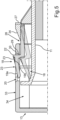
- FIG. 5 The coupling state between the coupling element 18 and the coupling receptacle 20 is shown in a frontal sectional view.
- a sectional view along the section line VV in Fig. 2 shown.
- an actuating element for example a finger
- the coupling element 18 is pressed inwards. This takes place until the Fig. 5 the release state of the coupling element 18 shown symbolically and in dashed lines is reached. In this release state, the coupling element 18 does not penetrate into the coupling receptacle 20 in the width direction.
- the Coupling element 18 can be guided through a gap 34 between a lateral edge region 33 or a wall part of the front wall 13, in which the coupling receptacle 20 is formed, and the side wall 11.
- the height of the limiting web 21 measured in the width direction is designed such that this coupling element 18 can be guided forwards past the edge region 33 in this gap 34 in the depth direction in this release state.
- the wall step 29 is not completely vertical, but is slightly inclined forwards from the holding part 26. In this regard, a demolding slope is formed.
Landscapes
- Engineering & Computer Science (AREA)
- Chemical & Material Sciences (AREA)
- Combustion & Propulsion (AREA)
- Physics & Mathematics (AREA)
- Mechanical Engineering (AREA)
- Thermal Sciences (AREA)
- General Engineering & Computer Science (AREA)
- Table Devices Or Equipment (AREA)
- Cookers (AREA)
- Packages (AREA)
Description
- Ein Aspekt der Erfindung betrifft einen Lebensmittel-Aufnahmebehälter. Der Lebensmittel-Aufnahmebehälter weist eine Behälterwanne auf. Diese weist eine Bodenwand und Seitenwände auf. Darüber hinaus weist der Lebensmittel-Aufnahmebehälter eine zur Behälterwanne separate Frontwand auf. Die Frontwand ist bewegbar an der Behälterwanne angeordnet. Der Lebensmittel-Aufnahmebehälter weist des Weiteren eine Koppelvorrichtung auf, mit welcher die Frontwand und die Behälterwanne in einem Koppelzustand der Koppelvorrichtung direkt miteinander gekoppelt sind und mit welcher die geschlossene Endposition der Frontwand an der Behälterwanne gehalten ist. Diese Koppelvorrichtung weist ein betätigbares Koppelelement auf, welches im Koppelzustand in eine Koppelaufnahme der Koppelvorrichtung eingreift. Das Koppelelement weist eine nach außen orientierte und freiliegende Betätigungsfläche zum berührenden Betätigen mit einem Betätigungselement auf. Ein weiterer Aspekt der Erfindung betrifft ein Haushaltskältegerät mit zumindest einem derartigen Lebensmittel-Aufnahmebehälter.
- Schalenförmige beziehungsweise wannenförmige Kühlgutbehälter, die auch als Lebensmittel-Aufnahmebehälter bezeichnet werden können, sind in vielfältigen Ausgestaltungen bekannt. In dem Zusammenhang gibt es einstückig ausgebildete Behälter. Bei diesen Ausgestaltungen ist die Frontwand einstückig mit den Seitenwänden und der Bodenwand ausgebildet. Bei diesen Ausführungsbeispielen ist jedoch die Reinigbarkeit des Volumenaufnahmeraums dieses Lebensmittel-Aufnahmebehälters erschwert. Insbesondere Übergangsbereiche zwischen den genannten Wänden und der Bodenwand sind innen schwerer zu reinigen.
- Insbesondere auch in dem Zusammenhang sind deswegen auch Ausführungsbeispiele von Lebensmittel-Aufnahmebehältern bekannt, bei denen die Frontwand bewegbar zu dem restlichen Körper, nämlich der Behälterwanne, ausgebildet ist. Dadurch kann eine Frontwand von der Behälterwanne weggeklappt werden und somit auch eine frontseitige Zugänglichkeit einfach ermöglicht werden. Insbesondere ist dadurch die Reinigbarkeit des Inneren dieses Lebensmittel-Aufnahmebehälters verbessert.
- Derartige Ausführungsbeispiele sind aus der
EP 2 591 297 B1 bekannt. Dort ist auch ein seitlich zugängliches Betätigungselement in Form eines Druckknopfs vorhanden. Dieser kann in Breitenrichtung des dortigen Kühlgutbehälters eingedrückt werden und damit die Koppelvorrichtung gelöst werden. Damit kann auch der geschlossene Zustand der Frontwand gelöst werden. Dieses Betätigungselement weist eine nach außen liegende Betätigungsfläche auf, die eben ist. - Darüber hinaus ist aus der
EP 2 702 338 B1 ein entsprechendes Konzept eines Lebensmittel-Aufnahmebehälters bekannt. Dort ist das Betätigungselement ein Schnappelement. Dieses weist eine Schnappplatte auf. Die Schnappplatte bildet ein vorderes Ende dieses Betätigungselements. Die Schnappplatte weist eine nach außen orientierte Oberfläche auf, die uneben ausgebildet ist. Auf diese Betätigungsfläche muss gedrückt werden, um dieses Betätigungselement in Breitenrichtung bewegen zu können und somit den gekoppelten Zustand lösen zu können. -
CN 110440498 A offenbart einen Lebensmittelbehälter mit einer Schale zur Aufnahme von Lebensmitteln und einer Frontwand, wobei die Frontwand beweglich an der Schale angeordnet ist. Die Frontwand kann mittels einer Schnappverbindung fixiert werden. -
CN 203258961 offenbart eine Schale mit einer entfernbaren Frontwand, wobei die Frontwand seitliche Öffnungen aufweist und der Schalenkörper seitliche Haken aufweist, die in die Öffnungen eingreifen. -
DE 10 2016 221 936 A1 offenbart eine Lebensmittel-Aufnahmeschale für ein Haushaltskältegerät, mit einem Aufnahmekörper und einer Frontwand, die an dem Aufnahmekörper frontseitig angeordnet ist, wobei der Aufnahmekörper eine Schalenwanne aufweist, die einen der Frontwand zugewandten Frontrand aufweist, und einen zumindest bereichsweise umlaufenden Kragen aufweist, der seitlich nach außen über den Frontrand der Schalenwanne überstehend angeordnet ist, wobei der Kragen eine der Frontwand abgewandt orientierte Anlagewand aufweist. - Aufgrund der dortigen Ausgestaltung des Betätigungselements ist jedoch eine zielführende und nutzerfreundliche Betätigung eingeschränkt. Gegebenenfalls kann ein unzureichender Entkoppelvorgang erfolgen, wenn der Nutzer mit seinem Finger diese Betätigungsfläche ungenau kontaktiert.
- Es ist Aufgabe der vorliegenden Erfindung, einen Lebensmittel-Aufnahmebehälter sowie ein Haushaltskältegerät zu schaffen, bei welchem die Betätigung eines Betätigungselements einer derartigen Koppelvorrichtung verbessert ist.
- Diese Aufgabe wird durch einen Lebensmittel-Aufnahmebehälter und ein Haushaltskältegerät gemäß den unabhängigen Ansprüchen gelöst.
- Ein Aspekt der Erfindung betrifft einen Lebensmittel-Aufnahmebehälter. Dieser Lebensmittel-Aufnahmebehälter weist eine Behälterwanne auf. Die Behälterwanne weist eine Bodenwand und Seitenwände auf. Darüber hinaus weist der Lebensmittel-Aufnahmebehälter eine zur Behälterwanne separate Frontwand auf. Die Frontwand ist an der Behälterwanne bewegbar angeordnet. Der Lebensmittel-Aufnahmebehälter weist des Weiteren eine mechanische Koppelvorrichtung auf, mit welcher die Frontwand und die Behälterwanne mechanisch miteinander koppelbar sind. In einem Koppelzustand der Koppelvorrichtung sind dann die Frontwand und die Behälterwanne direkt miteinander gekoppelt. Mit der Koppelvorrichtung ist darüber hinaus auch die geschlossene Endposition der Frontwand an der Behälterwanne gehalten. Die Koppelvorrichtung weist zumindest ein betätigbares Koppelelement auf. Dieses greift im Koppelzustand in eine Koppelaufnahme der Koppelvorrichtung ein. Das Koppelelement weist eine nach außen orientierte und freiliegende Betätigungsfläche auf, die bestimmungsgemäß zum berührenden Betätigen mit einem Betätigungselement ausgebildet ist. Durch das gezielte Betätigen dieser Betätigungsfläche ist dann bestimmungsgemäß das Lösen des Koppelzustands ermöglicht. Das Koppelelement weist einen von der Betätigungsfläche erhaben abstehenden Begrenzungssteg auf. Durch diesen Begrenzungssteg beziehungsweise eine erhabene Randeinfassung ist ein Positionierhilfsanschlag für das Betätigungselement auf der Betätigungsfläche gebildet. Durch eine derartige Ausgestaltung ist also das Koppelelement im Betätigungsbereich spezifisch gestaltet. Indem nicht mehr nur die Betätigungsfläche vorhanden ist, sondern eine diesbezüglich erhabene Begrenzung, ist ein zielgerichtetes Positionieren des Betätigungselements, insbesondere eines Fingers eines Nutzers, auf der Betätigungsfläche ermöglicht.
- Da durch den Begrenzungssteg im Wesentlichen die richtige Position für den Finger auf der Betätigungsfläche vorgegeben wird, ist auch ein sehr nutzerfreundliches und richtiges Betätigen ermöglicht. Insbesondere ist somit das Drücken auf die Betätigungsfläche zum Lösen des Koppelzustandes verbessert. Denn ein gegebenenfalls stark asymmetrisches Auflegen des Fingers auf die Betätigungsfläche und ein daraus resultierendes klemmendes oder verspreizendes Betätigen des Koppelelements zum Lösen des Koppelzustands ist dadurch vermieden. Dieser Begrenzungssteg unterstützt somit eine sehr zentrale Positionierung des Betätigungselements, insbesondere des Fingers, auf der Betätigungsfläche. Damit ist auch die Krafteinwirkung von dem Betätigungselement, insbesondere dem Finger, auf die Betätigungsfläche verbessert. Eine geradlinigere Krafteinwirkung ist dadurch erzielt, sodass der Lösevorgang des Koppelzustands besonders vorteilhaft ermöglicht ist. Darüber hinaus ist durch diesen Begrenzungssteg auch ermöglicht, dass beim Drücken mit dem Betätigungselement auf die Betätigungsfläche ein Abrutschen dieses Betätigungselements von der Betätigungsfläche verbessert verhindert ist.
- Durch diesen Begrenzungssteg wird somit auch zumindest eine teilweise, insbesondere eine nur teilweise, Einfassung gebildet. Der auf die Betätigungsfläche aufgelegte Finger ist durch diesen Begrenzungssteg somit auch teilweise umgriffen und in seiner Position auf der Betätigungsfläche dadurch gehalten.
- Erfindungsgemäß ist das Koppelelement ein federndes Drückelement. Ein besonders leichtgängiges Betätigen ist dadurch ermöglicht. Insbesondere ist damit auch das automatische Federn des Koppelelements in dem Grundzustand erreicht, wenn das Koppelelement nicht im gekoppelten Zustand mit der Koppelaufnahme vorliegt. Des Weiteren ist durch dieses federnde Drückelement auch erreicht, dass beim Koppeln zwischen dem Koppelelement und der Koppelaufnahme das Koppelelement zunächst aus dem Grundzustand herausbewegt wird und dadurch eine gewisse federnde Vorspannung bewirkt wird. Ist dann diejenige Position erreicht, bei welcher ein Teilelement, insbesondere ein Eingriffsstück, des Koppelelements in die Koppelaufnahme eintaucht, erfolgt dies auch automatisch, da diese federnde Vorspannung bewirkt, dass dieses Teilelement in die Koppelaufnahme einschnappt. Durch dieses federnde Drückelement wird dann auch der Koppelzustand verbessert gehalten. Denn insbesondere kann in einem Ausführungsbeispiel vorgesehen sein, dass das Koppelelement in dem Koppelzustand weiterhin federnd vorgespannt in der Koppelaufnahme angeordnet ist. Ein unerwünschtes Lösen dieses Koppelzustands ist dadurch verbessert verhindert.
- In einem Ausführungsbeispiel ist die Betätigungsfläche in Breitenrichtung des Lebensmittel-Aufnahmebehälters betrachtet zur Seite hin freiliegend. Das Koppelelement ist in Breitenrichtung bewegbar und insbesondere in dem Koppelzustand zu lösen. Durch diese Positionierung ist auch eine einerseits einfache Zugänglichkeit für einen Nutzer ermöglicht und ein einfaches Bedienkonzept erreicht. Andererseits ist durch diese spezifische Position die Frontwand frei von einem derartigen Koppelelement. Somit ist insbesondere auch vermieden, dass durch unerwünschtes frontseitiges Anstoßen an der Frontwand des Lebensmittel-Aufnahmebehälters ein Lösen des Koppelzustands auftreten würde. Durch diese seitliche Positionierung ist somit ein unerwünschtes Lösen des Koppelzustands vermieden.
- Darüber hinaus ist eine derartige seitliche Anordnung mit einem aufgeräumteren Zustand und einem beruhigteren frontseitigen Erscheinungsbild des Lebensmittel-Aufnahmebehälters einhergehend.
- Gemäß einer ersten erfindungsgemäßen Variante weist der Begrenzungssteg ein vertikales Stegteil auf. Dies bedeutet, dass dieses Stegteil in Höhenrichtung des Lebensmittel-Aufnahmebehälters orientiert ist. Dies ist ein besonders vorteilhaftes Ausführungsbeispiel. Denn einerseits ist somit eine Bewegung des Betätigungselements, die zumindest anteilig nach hinten beziehungsweise in Tiefenrichtung des Lebensmittel-Aufnahmebehälters erfolgt, begrenzt. Der Finger stößt bei einer derartigen Annäherungsbewegung dann an diesem vertikalen Stegteil an. Damit wird in vorteilhafter Weise ein nach hinten überstehendes oder nach hinten wegrutschendes Positionieren des Betätigungselements auf der Betätigungsfläche vermieden. Ein weiterer Vorteil dieses Ausführungsbeispiels ist darin zu sehen, dass durch dieses vertikale Stegteil eine Koppelwand des Koppelelements, die zum Übergreifen beziehungsweise Hintergreifen einer Koppelaufnahme bestimmungsgemäß vorgesehen ist, erhöht ist. Damit kann der Koppelzustand verbessert werden. Denn ein unerwünschtes Lösen ist dadurch verbessert vermieden. Insbesondere auch dann, wenn beispielsweise durch Krafteinwirkungen des Lebensmittel-Aufnahmebehälters auch Relativbewegungen zwischen dem Koppelelement und der Koppelaufnahme, insbesondere in Breitenrichtung des Lebensmittel-Aufnahmebehälters, bewirkt werden, ist ein unerwünschtes Lösen des Koppelzustands vermieden. Denn somit ist gerade in Breitenrichtung des Lebensmittel-Aufnahmebehälters die Überlappung zwischen dem Koppelelement und der Koppelaufnahme durch dieses vertikale Stegteil vergrößert.
- Alternativ oder zusätzlich gemäß einer zweiten erfindungsgemäßen Variante weist der Begrenzungssteg ein oberes, horizontales Stegteil und/oder ein unteres, horizontales Stegteil auf. Dies ist in Höhenrichtung des Lebensmittel-Aufnahmebehälters betrachtet. Die horizontale Orientierung ist in dem Zusammenhang vorteilhaft in Tiefenrichtung des Lebensmittel-Aufnahmebehälters gerichtet. Durch diese weiteren Stegteile kann eine Begrenzung nach oben und/oder nach unten hin erreicht werden. Auch dadurch kann das Berühren der Betätigungsfläche durch das Betätigungselement ortsgenau erfolgen beziehungsweise dieses ortsgenaue Berühren vorteilhaft unterstützt werden. Ein zu weit oben erfolgendes Berühren oder ein zu weit unten erfolgendes Berühren der Betätigungsfläche ist dadurch vermieden.
- Darüber hinaus ist durch diese horizontalen Stegteile eine Erhöhung der Steifigkeit des Koppelelements in diesem Bereich ermöglicht.
- Es kann in einem Ausführungsbeispiel vorgesehen sein, dass ein horizontales Stegteil direkt an dem vertikalen Stegteil endet. Somit ist ein zusammenhängender beziehungsweise unterbrechungsfreier Begrenzungssteg gebildet, der nicht geradlinig ausgebildet ist. Die oben genannten Vorteile bezüglich der einzelnen Stegteile werden hier nochmals verbessert, da sie in Wirkverbindung mit zumindest zwei Raumrichtungen erreicht werden.
- In einem Ausführungsbeispiel ist der Begrenzungssteg U-förmig ausgebildet. Damit sind die oben genannten Vorteile bezüglich der Positioniergenauigkeit des Betätigungselements auf der Betätigungsfläche, der Abrutschsicherheit und auch der mechanischen Steifigkeit dieses Teilbereichs des Koppelelements erreicht.
- In einem Ausführungsbeispiel sind die Betätigungsfläche und der Begrenzungssteg einstückig miteinander ausgebildet. Damit kann die Bauteilzahl reduziert werden und die Position in der genannten Komponente zueinander ist dauerhaft gegeben.
- In einem Ausführungsbeispiel ist das gesamte Koppelelement einstückig ausgebildet. Es kann beispielsweise aus Kunststoff ausgebildet sein.
- In einem Ausführungsbeispiel ist das Koppelelement einstückig mit einer Seitenwand der Behälterwanne ausgebildet. Es ist insbesondere, in Tiefenrichtung des Lebensmittel-Aufnahmebehälters betrachtet, in einem vorderen Bereich dieser Seitenwand integriert ausgebildet.
- In einem Ausführungsbeispiel ist die Koppelaufnahme in der Frontwand ausgebildet, insbesondere einstückig damit ausgebildet. Die Koppelaufnahme kann in einem Ausführungsbeispiel ein durchgängiges Loch in einem Wandbereich der Frontwand sein.
- Die Koppelaufnahme erstreckt sich flächig insbesondere in einer Ebene, die durch die Tiefenrichtung und die Höhenrichtung des Lebensmittel-Aufnahmebehälters ausgebildet ist.
- In einem Ausführungsbeispiel ist die Betätigungsfläche uneben. Die Betätigungsfläche weist in diesem Ausführungsbeispiel eine in Tiefenrichtung des Lebensmittel-Aufnahmebehälters vordere Betätigungsteilfläche auf. Die Betätigungsfläche weist bei diesem Ausführungsbeispiel insbesondere eine nach hinten an die vordere Betätigungsteilfläche direkt anschließende hintere Betätigungsteilfläche auf. Diese beiden Betätigungsteilflächen sind geneigt zueinander angeordnet.
- Durch dieses Ausführungsbeispiel ist in Verbindung mit dem Begrenzungssteg ein gewisser Vertiefungs- beziehungsweise Muldenbereich an dem Koppelelement gebildet. Die noch zielgerichtetere, positionsstabile Berührung der Betätigungsfläche mit dem Betätigungselement, insbesondere mit einem Finger, ist dadurch ermöglicht. Der Positionierhilfsanschlag ist dadurch verbessert.
- In einem Ausführungsbeispiel ist der Begrenzungssteg an dieser hinteren Betätigungsfläche direkt angeordnet. Er ist von dieser hinteren Betätigungsfläche seitlich nach außen erhaben abstehend. Damit kann in vorteilhafter Weise das Berühren der Betätigungsfläche insbesondere an der hinteren Betätigungsteilfläche zielgerichtet und genau erfolgen. Damit ist ein besonders vorteilhafter gewünschter Betätigungsvorgang dieses Betätigungselements ermöglicht. Ein diesbezüglich quasi optimaler Druckpunkt des Betätigungselements auf das Koppelelement ist dadurch ermöglicht.
- Diesbezüglich muss somit ein Nutzer nicht mehr erahnen, wo ein derartiger optimaler Druckpunkt sein könne beziehungsweise verfehlt diesen optimalen Druckpunkt auf der Betätigungsfläche nicht mehr. Allein schon optisch kann er nun erkennen, wo die beste Position auf der Betätigungsfläche ist, um den diesbezüglich besten Betätigungsvorgang zum Lösen des Koppelzustands durchführen zu können.
- In einem Ausführungsbeispiel ist die Höhe des Begrenzungsstegs so gebildet, dass eine Oberkante des Begrenzungsstegs, insbesondere die gesamt Oberkante, in einer Ebene mit der vorderen Betätigungsteilfläche liegt. Die Oberkante des Begrenzungsstegs ist dabei derjenige freie Rand des Begrenzungsstegs, der der Betätigungsteilfläche abgewandt ist. Der Begrenzungssteg endet direkt auf dieser hinteren Betätigungsteilfläche. Er erhebt sich somit aus der Ebene dieser hinteren Betätigungsteilfläche heraus und erstreckt sich somit in Breitenrichtung des Lebensmittel-Aufnahmebehälters ausgehend von der unteren Betätigungsteilfläche seitlich nach außen. Die Höhe des Begrenzungsstegs ist in dem Zusammenhang zwischen der hinteren Betätigungsteilfläche und der Oberkante des Begrenzungsstegs bemessen.
- Durch das oben genannte vorteilhafte Ausführungsbeispiel ist eine vorteilhafte Geometrie erreicht. Denn nach außen hin steht somit der Begrenzungssteg nicht über die Betätigungsfläche in ihrer Gesamtheit betrachtet über. Sie erreicht somit insbesondere in dieser Breitenrichtung maximal die Position, die auch von der vorderen Betätigungsteilfläche erreicht wird. Durch diese Ausgestaltung des Begrenzungsstegs kann auch ein kantenfreier Übergang der Oberkante zur vorderen Betätigungsteilfläche erreicht werden. Ein unerwünschtes Anstoßen des Fingers an derartigen Kanten kann dadurch vermieden werden. Damit ist auch ein besonders nutzerfreundliches Bedienkonzept ermöglicht.
- In einem Ausführungsbeispiel weist das Koppelelement ein Eingriffsstück auf. Dieses Eingriffsstück ist bestimmungsgemäß zum direkten Eingreifen in die Koppelaufnahme vorgesehen. Das Koppeln erfolgt somit insbesondere zwischen dem Eingriffsstück und der Koppelaufnahme. Dieses Eingriffsstück weist diese Betätigungsfläche auf. Insbesondere ist die gesamte Betätigungsfläche an dem Eingriffsstück ausgebildet. Das Koppelelement weist ein an das Eingriffsstück endendes Halteteil auf. Mit diesem Halteteil ist das Koppelelement an der Behälterwanne angeordnet beziehungsweise endet dort. Zwischen dem Halteteil und dem Eingriffsstück ist eine Wandstufe des Koppelelements gebildet. Diese Wandstufe ist bestimmungsgemäß dazu vorgesehen, dass sie im gekoppelten Zustand des Koppelelements mit der Koppelaufnahme in diese Koppelaufnahme eintaucht. Diese Wandstufe ist somit im gekoppelten Zustand in einer Raumrichtung, insbesondere in der Breitenrichtung des Lebensmittel-Aufnahmebehälters, mit dem Begrenzungsrand der Koppelaufnahme überlappend. Damit ist der verschnappte Zustand erreicht.
- Darüber hinaus ist bei diesem vorteilhaften Ausführungsbeispiel die bereits oben erläuterte Möglichkeit der Wandstufenerhöhung durch die gezielte Anordnung des vertikalen Stegteils unterstützt. Denn damit wird diese Wandstufe vergrößert. Die Eintauchtiefe des Eingriffsstücks in die Koppelaufnahme ist dadurch ebenfalls vergrößert. In besonders vorteilhafter Weise wird somit ein unerwünschtes Lösen des Koppelzustands verhindert, wenn beispielsweise durch Krafteinwirkung eine Relativbewegung in Breitenrichtung zwischen dem Koppelelement und der Koppelaufnahme in diesem Koppelzustand auftritt. Dies kann beispielsweise aufgrund von rollenden Lagergütern im Lebensmittel-Aufnahmebehälter erfolgen, die dann an Wänden des Behälters anstoßen. Auch beispielsweise ein Herausziehen oder Hineinschieben des Lebensmittel-Aufnahmebehälters in einen Aufnahmeraum eines Haushaltskältegeräts kann dazu führen, dass diesbezügliche Relativbewegungen zwischen der Frontwand und der Behälterwanne auftreten und diesbezüglich auch entsprechende Relativbewegungen in Breitenrichtung zwischen dem Koppelelement und der Koppelaufnahme im Koppelzustand auftreten.
- Insbesondere sind die Wandstufe und der Begrenzungssteg, insbesondere das vertikale Stegteil, an deren Außenseiten bündig zueinander angeordnet.
- In einem Ausführungsbeispiel weist der Begrenzungssteg eine Höhe auf, sodass das Koppelelement zwischen einer die Koppelaufnahme aufweisenden Wand der Frontwand und der Seitenwand der Behälterwanne bestimmungsgemäß insbesondere in Tiefenrichtung, hindurchführbar ist. Somit ist auch ein einfaches Koppeln und Entkoppeln ermöglicht.
- Allgemein betrachtet ist somit ein Lebensmittel-Aufnahmebehälter geschaffen, der vielfältigste Vorteile bietet. Es ist insbesondere eine verbesserte Erkennung der besonders vorteilhaften Berührposition des Betätigungselements auf dieser Betätigungsfläche erreicht. Darüber hinaus ist gerade auch durch den Begrenzungssteg eine haptische Rückmeldung für den Nutzer ermöglicht, wenn er mit seinem Finger auf die Betätigungsfläche greift und diesbezüglich auch den Begrenzungssteg berührt. Es kann somit quasi auch ein unmittelbares Rückmelden an den Nutzer erfolgen, wo der bestmögliche Druckpunkt auf der Betätigungsfläche ist.
- Darüber hinaus ist durch die vorgeschlagene Lösung auch eine einfache Herstellung ermöglicht. Insbesondere wenn die Frontwand und die Behälterwanne jeweils aus Kunststoff, insbesondere als Spritzgussbauteile, hergestellt sind, ist der Fertigungsprozess sehr einfach. Bestehende Spritzgusswerkzeuge müssen quasi nicht verändert werden. Da die Formgebung des Begrenzungsstegs sehr einfach ist, können diesbezügliche Werkzeuge auch einfach angepasst werden. Der Materialbedarf für diesen Begrenzungssteg ist in dem Zusammenhang quasi vernachlässigbar.
- Durch den Begrenzungssteg ist auch erreicht, dass beim Überfahren der Betätigungsfläche von vorne her kommend der Nutzer mit seinem Finger als Betätigungselement an diesen Begrenzungssteg anstößt, wodurch er einfach erkennt, dass die bevorzugte Betätigungsposition auf der Betätigungsfläche erreicht ist. Insbesondere liegt dann die Fingerspitzenmitte direkt auf dem bestmöglichen Druckpunkt auf der Betätigungsfläche auf.
- Gerade dann, wenn das Koppelelement als Spritzgussteil hergestellt ist, ist in dem vorteilhaften Ausführungsbeispiel, in dem die Wandstufe zwischen dem Eingriffsstück und dem Halteteil ausgebildet ist, eine theoretisch vollständige vertikale Wandstufe erreichbar. Aufgrund von erforderlichen Entformschrägen ist diese Wandstufe etwas geneigt. Gerade um bei derartigen Ausführungsbeispielen das bereits oben erläuterte unerwünschte Lösen des Koppelzustands zu vermeiden, ist der Begrenzungssteg hier ein weiterer Vorteil. Denn selbst bei einer diesbezüglich geringfügig geneigten Wandstufe ist durch die Erhöhung dieser Wand mit dem Begrenzungssteg ein derartiges seitliches Herausrutschen des Koppelelements aus der Koppelaufnahme bei leichten Anstoßkräften in Breitenrichtung vermieden. In dieser Breitenrichtung ist durch den Begrenzungssteg somit diese Toleranz der Relativbewegung zwischen dem Koppelelement und der Koppelaufnahme im Koppelzustand erhöht.
- Ein weiterer Vorteil ist darin zu sehen, dass das Koppeln zwischen dem Koppelelement und der Koppelaufnahme durch die Erfindung oder ein vorteilhaftes Ausführungsbeispiel davon bezüglich eines akustischen Einschnappens etwas lauter ist. Somit kann der verschnappte Endzustand akustisch besser wahrgenommen werden.
- Insbesondere ist durch das vorgeschlagene Konzept auch quasi ein blindes Koppeln und Entkoppeln für einen Nutzer einfacher und besser ermöglicht. Dies bedeutet, dass der Nutzer nicht explizit auf das Koppelelement und die Koppelaufnahme blicken muss, um den Koppelzustand lösen zu können.
- Ausführungsbeispiele der Erfindung werden nachfolgend anhand schematischer Zeichnungen näher erläutert. Es zeigen:
- Fig. 1
- eine schematische perspektivische Darstellung eines Ausführungsbeispiels eines erfindungsgemäßen Haushaltskältegeräts;
- Fig. 2
- eine perspektivische Darstellung eines Ausführungsbeispiels eines erfindungsgemäßen Lebensmittel-Aufnahmebehälters;
- Fig. 3
- eine perspektivische Darstellung eines Teilbereichs der Behälterwanne des Lebensmittel-Aufnahmebehälters, mit einem Ausführungsbeispiel eines Koppelelements einer Koppelvorrichtung gezeigt ist;
- Fig. 4
- eine perspektivische Darstellung eines Teilbereichs in
Fig. 2 ; und - Fig. 5
- eine Schnittdarstellung durch einen Teilbereich des Lebensmittel-Aufnahmebehälters gemäß
Fig. 2 , in dem einerseits der Koppelzustand zwischen der Koppelaufnahme und dem Koppelelement gezeigt ist, andererseits gestrichelt auch der Lösezustand zwischen der Koppelaufnahme und dem Koppelelement angedeutet ist. - In den Figuren werden gleiche oder funktionsgleiche Elemente mit den gleichen Bezugszeichen versehen.
- In
Fig. 1 ist in einer schematischen Darstellung ein Haushaltskältegerät 1 gezeigt. Das Haushaltskältegerät 1 ist zum Lagern und Konservieren von Lebensmitteln ausgebildet. Das Haushaltskältegerät 1 kann ein Kühlgerät oder ein Gefriergerät oder ein Kühl-Gefrier-Kombigerät sein. Das Haushaltskältegerät 1 weist ein Gehäuse 2 auf. In dem Gehäuse 2 ist ein Innenbehälter 3 angeordnet. Der Innenbehälter 3 begrenzt mit Wänden einen Aufnahmeraum 4 für Lebensmittel. Der Aufnahmeraum 4 kann ein Kühlfach oder ein Gefrierfach sein. Des Weiteren weist das Haushaltskältegerät 1 eine Tür 5 auf. Diese ist bewegbar an dem Gehäuse 2 angeordnet. Sie ist zum hier frontseitigen Verschließen des Aufnahmeraums 4 vorgesehen. - Schematisch gezeigt ist in dem Aufnahmeraum 4 ein Lebensmittel-Aufnahmebehälter 6 angeordnet. Dieser kann auch als Kühlgutbehälter bezeichnet werden.
- In
Fig. 2 ist in einer perspektivischen Darstellung ein Ausführungsbeispiel eines Lebensmittel-Aufnahmebehälters 6 gezeigt. Der Lebensmittel-Aufnahmebehälter 6 weist eine Behälterwanne 7 auf. Diese Behälterwanne 7 weist eine Bodenwand 8, eine Rückwand 9 und gegenüberliegende Seitenwände 10 und 11 auf. Durch die Behälterwanne 7 ist ein Volumenraum 12 gebildet, in den die Lagergüter eingebracht werden können. Die Behälterwanne 7 ist in einem Ausführungsbeispiel einstückig ausgebildet. Sie ist insbesondere aus Kunststoff ausgebildet. - Der Lebensmittel-Aufnahmebehälter 6 weist darüber hinaus eine Frontwand 13 auf. Die Frontwand 13 ist eine zur Behälterwanne 7 separate Komponente. Sie kann einstückig ausgebildet sein. Sie kann beispielsweise aus Kunststoff ausgebildet sein.
- In
Fig. 2 ist die Frontwand 13 in ihrer geschlossenen Endposition an der Behälterwanne 7 gezeigt. Die Frontwand 13 bildet in dem Zusammenhang eine weitere vertikale Begrenzungswand, insbesondere eine frontseitige Begrenzungswand, des Volumenraums 12. Die Frontwand 13 ist bewegbar zu der Behälterwanne 7 angeordnet. Sie kann auch vollständig von der Behälterwanne 7 abgenommen werden. Dies kann zerstörungsfrei lösbar erfolgen. - Der Lebensmittel-Aufnahmebehälter 6 weist eine Koppelvorrichtung 14 auf. Mit dieser mechanischen Koppelvorrichtung 14 ist die Frontwand 13 direkt mit der Behälterwanne 7 mechanisch gekoppelt. Darüber hinaus ist auch die in
Fig. 2 gezeigte geschlossene Endposition der Frontwand 13 an der Behälterwand 7 durch diese Koppelvorrichtung 14 gehalten. - In Tiefenrichtung (z-Richtung) ist ein Teilelement dieser Koppelvorrichtung 14 in einem vorderen beziehungsweise frontseitigen Bereich der Seitenwand 11 ausgebildet. Insbesondere ist auch an der gegenüberliegenden Seitenwand 10 ein entsprechendes Teilelement der Koppelvorrichtung 14 vorhanden, um beidseits eine entsprechende mechanische Kopplung mit der Frontwand 13 zu erreichen.
- Wie zu erkennen ist, ist diese Koppelvorrichtung 14 in Höhenrichtung (y-Richtung) betrachtet im unteren Bereich zwischen der Seitenwand 11 und der Frontwand 13 sowie im unteren Bereich zwischen der Seitenwand 10 und der Frontwand 13 ausgebildet.
- In einem Ausführungsbeispiel ist auch vorgesehen, dass in Höhenrichtung in einem oberen Bereich eine mechanische Kopplung zwischen den Seitenwänden 10 und 11 einerseits und der Frontwand 13 andererseits ausgebildet ist. Diesbezüglich sind lediglich einfache Eingriffselemente 15 und 16 an den Seitenwänden 10 und 11 ausgebildet, die in entsprechende Aufnahmen in der Frontwand 13 eingreifen.
- In
Fig. 3 ist in einer vergrößerten Darstellung eine perspektivische Ansicht eines unteren Eckbereichs 17 der Seitenwand 11 gezeigt. In diesem Ausführungsbeispiel ist ein Koppelelement 18 der Koppelvorrichtung 14 einstückig mit dieser Seitenwand 11 ausgebildet. Das Koppelelement 18 ist darüber hinaus ebenfalls einstückig ausgebildet. Das Koppelelement 18 ist hier als federndes Drückelement ausgebildet. Es ist insbesondere in Breitenrichtung (x-Richtung) federnd ausgebildet. Das Koppelelement 18, welches Bestandteil der Koppelvorrichtung 14 ist, weist eine Betätigungsfläche 19 auf. Die Betätigungsfläche 19 ist bestimmungsgemäß dazu vorgesehen, dass sie direkt mit einem Betätigungselement, beispielsweise einem Finger eines Nutzers, berührt werden kann und betätigt werden kann. Insbesondere ist diesbezüglich eine definierte Krafteinwirkung in dieser Breitenrichtung vorgesehen. Dadurch kann ein Koppelzustand zwischen dem Koppelelement 18 und einer Koppelaufnahme 20 (Fig. 4 ), die ebenfalls Bestandteil der Koppelvorrichtung 14 ist, gelöst werden. - Im Ausführungsbeispiel ist diese in Breitenrichtung seitlich und somit nach außen frei liegende Betätigungsfläche 19 uneben ausgebildet. Sie weist eine in Tiefenrichtung (z-Richtung) vordere Betätigungsteilfläche 19a auf. In Tiefenrichtung unmittelbar nach hinten direkt daran anschließend weist die Betätigungsfläche 19 eine zweite, hintere Betätigungsteilfläche 19b auf. In einem Ausführungsbeispiel sind diese beiden Betätigungsteilflächen 19a und 19b geneigt zueinander angeordnet. Es kann in einem Ausführungsbeispiel vorgesehen sein, dass die Betätigungsteilfläche 19a eben ist. Ebenso kann vorgesehen sein, dass die hintere Betätigungsteilfläche 19b eben ist. Die beiden Betätigungsteilflächen 19a und 19b münden an einem Übergang 19c aneinander an.
- In einem Ausführungsbeispiel ist die zweite, hintere Betätigungsteilfläche 19b ausgehend von dem Ende, welches an die vordere Betätigungsteilfläche 19a endet, nach innen zu der Seitenwand 11 hin geneigt. Dies bedeutet, dass das hintere Ende dieser hinteren Betätigungsteilfläche 19b in Breitenrichtung betrachtet näher zur Seitenwand 11 angeordnet ist, als das der vorderen Betätigungsteilfläche 19a zugewandte vordere Ende.
- Darüber hinaus weist das Koppelelement 18 einen Begrenzungssteg 21 auf. Der Begrenzungssteg 21 ist erhaben von der Betätigungsfläche 19 abstehend. Er ist diesbezüglich in Breitenrichtung betrachtet seitlich nach außen von dieser Betätigungsfläche 19 abstehend.
- Der Begrenzungssteg 21 weist ein vertikales Stegteil 22 auf. Dieses ist somit in Höhenrichtung des Lebensmittel-Aufnahmebehälters orientiert. Der Begrenzungssteg 21 weist ein oberes, horizontales Stegteil 23 auf. Der Begrenzungssteg 21 weist ein unteres, horizontales Stegteil 24 auf.
- In einem Ausführungsbeispiel sind die Stegteile 22, 23 und 24 unterbrechungsfrei zueinander angeordnet und bilden somit einen zusammenhängenden Begrenzungssteg 21. In einem Ausführungsbeispiel weist der Begrenzungssteg 21 eine U-Form auf.
- Wie in dem Ausführungsbeispiel in
Fig. 3 gezeigt ist, ist der Begrenzungssteg 21 auf der hinteren Betätigungsteilfläche 19b ausgebildet und erstreckt sich ausgehend von dieser hinteren Betätigungsteilfläche 19b seitlich erhaben nach außen. - Im Ausführungsbeispiel ist vorgesehen, dass sich der Begrenzungssteg 21 nicht auf der vorderen Begrenzungsteilfläche 19a erstreckt. Er endet somit an dem Übergang 19c. Der Begrenzungssteg 21 ist insbesondere eine randseitige Einfassung der hinteren Betätigungsteilfläche 19b.
- Des Weiteren ist zu erkennen, dass diese Betätigungsfläche 19 mit dem Begrenzungssteg 21 an einem Eingriffsstück 25 des Koppelelements 18 ausgebildet ist. In Tiefenrichtung betrachtet ist dieses Eingriffsstück 25 das vordere Ende des Koppelelements 18. Es ist diesbezüglich nach vorne frei kragend orientiert. Dieses Eingriffsstück 25 ist bestimmungsgemäß zum direkten Eingreifen in die Koppelaufnahme 20 vorgesehen. Die Betätigungsfläche 19 ist in einem Ausführungsbeispiel ausschließlich und nur auf diesem Eingriffsstück 25 ausgebildet. Insbesondere ist der Begrenzungssteg 21 ausschließlich und vollständig in einem Ausführungsbeispiel nur auf diesem Eingriffsstück 25 ausgebildet.
- Das Koppelelement 18 weist in einem Ausführungsbeispiel darüber hinaus ein Halteteil 26 auf. Das Halteteil 26 endet an einem Wandbereich 27 dieser Seitenwand 11. Darüber hinaus ist dieses Halteteil 26 direkt an das Eingriffsstück 25 endend. In dem Zusammenhang ist an einem Übergang 28 zwischen dem Eingriffsstück 25 und dem Halteteil 26 eine Wandstufe 29 ausgebildet. Dies bedeutet, dass in Breitenrichtung betrachtet ein diskreter Versatz zwischen dem Eingriffsstück 25 und dem Halteteil 26 gebildet ist. Diesbezüglich ist in Breitenrichtung das Eingriffsstück 25 an dieser Wandstufe 29 weiter nach außen stehend als das Halteteil 26. Somit ist auch erreicht, dass nur das Eingriffsstück 25 in die Koppelaufnahme 20 in Breitenrichtung eintaucht, wie dies in
Fig. 4 gezeigt ist. Die Koppelaufnahme 20 ist in einem Ausführungsbeispiel, wie dies inFig. 4 gezeigt ist, ein durchgängiges Loch, in welches das Eingriffsstück 25 in Breitenrichtung betrachtet nach außen einschnappt und diesbezüglich eingreift. In Breitenrichtung ist somit dieses Eingriffsstück 25 überlappend an dieser Koppelaufnahme 20 angeordnet. Diesbezüglich kann diese hintere Wandstufe 29 insbesondere in einem mechanischen Kontakt mit einer inFig. 4 gezeigten Begrenzungswand 30 sein, welche den Lochbereich der Koppelaufnahme 20 nach hinten begrenzt. Diese Wandstufe 29 ist in Breitenrichtung mit dieser Begrenzungswand 30 beziehungsweise dem diesbezüglichen Begrenzungsrand überlappend angeordnet. - Wie in
Fig. 3 in dem Ausführungsbeispiel gezeigt ist, ist der Begrenzungssteg 21, insbesondere das vertikale Stegteil 22, an dem hinteren Ende des Eingriffsstücks 25 ausgebildet. Das vertikale Stegteil 22 ist außenseitig insbesondere bündig mit der Wandstufe 29 ausgebildet. Durch dieses vertikale Stegteil 22 ist die Wandstufe 29 in Breitenrichtung des Lebensmittel-Aufnahmebehälters betrachtet nach außen hin erhöht. Dadurch kann in Breitenrichtung betrachtet ein größeres Überlappen zwischen dem Eingriffsstück 25 und der Koppelaufnahme 20 im Koppelzustand erreicht werden, wie dies inFig. 4 gezeigt ist. - Durch den Begrenzungsrand 21 ist ein Positionierhilfsanschlag für das Betätigungselement, insbesondere einen Finger, gebildet. Dadurch ist es erreicht, dass bevorzugt ein Berührbereich 31 (
Fig. 3 ) auf der Betätigungsfläche 19 von diesem Betätigungselement quasi automatisch erreicht wird. Insbesondere ist dadurch erreicht, dass eine Fingerkuppenmitte eines Fingers im Wesentlichen mittig in der hinteren Betätigungsteilfläche 19b aufgelegt wird. Dies wird quasi durch den Begrenzungsrand 21 vorgegeben. - Wie darüber hinaus in
Fig. 3 auch zu erkennen ist, ist eine Oberkante 32 des Begrenzungsstegs 21 in einer Ebene ausgebildet. Insbesondere erstreckt sich diese Oberkante 32 in einer Ebene, in der sich auch die vordere Betätigungsteilfläche 19a flächig und eben erstreckt. - Wie bereits oben erwähnt, ist in
Fig. 4 der Teilausschnitt I inFig. 2 gezeigt. Es ist hier der Koppelzustand zwischen dem Koppelelement 18 und der Koppelaufnahme 20 gezeigt. - In
Fig. 5 ist in einer Frontalschnittdarstellung der Koppelzustand zwischen dem Koppelelement 18 und der Koppelaufnahme 20 gezeigt. Diesbezüglich ist eine Schnittdarstellung entlang der Schnittlinie V-V inFig. 2 gezeigt. Es ist somit eine Schnittdarstellung im Bereich der Koppelvorrichtung 14, die zwischen der vertikalen Seitenwand 10 und der Frontwand 13 ausgebildet ist, dargestellt. Selbiges gilt bezüglich der nachfolgenden Erläuterung auch für die Kopplung zwischen der Seitenwand 11 und der Frontwand 13. - Die durch den Begrenzungssteg 21, insbesondere das vertikale Stegteil 22, in Breitenrichtung vergrößerte Höhe der Wandstufe 29 ist zu erkennen. Dadurch ist die Eintauchtiefe des Koppelelements 18, insbesondere des Eingriffsstücks 25, in die Koppelaufnahme 20 erhöht.
- Wird dann von außen mit einem Betätigungselement, beispielsweise mit einem Finger, auf die Betätigungsfläche 19 im Bereich 31, insbesondere der hinteren Betätigungsteilfläche 19b, aufgedrückt und somit eine Kraft in Breitenrichtung erzeugt, so wird das Koppelelement 18 nach innen gedrückt. Dies erfolgt so weit, bis der in
Fig. 5 symbolisch und gestrichelt gezeigte Lösezustand des Koppelelements 18 erreicht ist. In diesem Lösezustand ist kein in Breitenrichtung vorhandenes Eintauchen des Koppelelements 18 in die Koppelaufnahme 20 ausgebildet. - Damit kann dann in Tiefenrichtung (z-Richtung) die Frontwand 13 von der Behälterwanne 7 abgenommen werden. In dem Zusammenhang ist es dann auch möglich, dass das Koppelelement 18 in einem Zwischenraum 34 zwischen einem seitlichen Randbereich 33 beziehungsweise einem Wandteil der Frontwand 13, in welchem die Koppelaufnahme 20 ausgebildet ist, und der Seitenwand 11 durchgeführt werden kann. Insbesondere ist es in dem Zusammenhang vorgesehen, dass die in Breitenrichtung bemessene Höhe des Begrenzungsstegs 21 so ausgebildet ist, dass dieses Koppelelement 18 in diesem Zwischenraum 34 in Tiefenrichtung in diesem Lösezustand an dem Randbereich 33 nach vorne vorbei hindurchgeführt werden kann.
- Es kann vorgesehen sein, dass die Wandstufe 29 nicht vollständig vertikal ist, sondern diesbezüglich geringfügig von dem Halteteil 26 nach vorne weg geneigt ist. Diesbezüglich ist eine Entformschräge ausgebildet.
-
- 1
- Haushaltskältegerät
- 2
- Gehäuse
- 3
- Innenbehälter
- 4
- Aufnahmeraum
- 5
- Tür
- 6
- Lebensmittel-Aufnahmebehälter
- 7
- Behälterwanne
- 8
- Bodenwand
- 9
- Rückwand
- 10
- Seitenwand
- 11
- Seitenwand
- 12
- Volumenraum
- 13
- Frontwand
- 14
- Koppelvorrichtung
- 15
- Eingriffselement
- 16
- Eingriffselement
- 17
- Eckbereich
- 18
- Koppelelement
- 19
- Betätigungsfläche
- 19a
- Betätigungsteilfläche
- 19b
- Betätigungsteilfläche
- 19c
- Übergang
- 20
- Koppelaufnahme
- 21
- Begrenzungssteg
- 22
- vertikales Stegteil
- 23
- oberes horizontales Stegteil
- 24
- unteres horizontales Stegteil
- 25
- Eingriffsstück
- 26
- Halteteil
- 27
- Wandbereich
- 28
- Übergang
- 29
- Wandstufe
- 30
- Begrenzungswand
- 31
- Berührbereich
- 32
- Oberkante
- 33
- Randbereich
- 34
- Zwischenraum
- x
- Breitenrichtung
- y
- Höhenrichtung
- z
- Tiefenrichtung
Claims (12)
- Lebensmittel-Aufnahmebehälter (6) mit einer Behälterwanne (7), welche eine Bodenwand (8) und Seitenwände (10, 11) aufweist, mit einer Frontwand (13), die an der Behälterwanne (7) bewegbar angeordnet ist, und mit einer Koppelvorrichtung (14), mit welcher die Frontwand (13) und die Behälterwanne (7) in einem Koppelzustand der Koppelvorrichtung (14) direkt miteinander gekoppelt sind und mit welcher die geschlossene Endposition der Frontwand (13) an der Behälterwanne (7) gehalten ist, wobei die Koppelvorrichtung (14) ein betätigbares Koppelelement (18) aufweist, welches im Koppelzustand in eine Koppelaufnahme (20) der Koppelvorrichtung (14) eingreift, wobei das Koppelelement (18) eine nach außen orientierte und frei liegende Betätigungsfläche (19) zum berührenden Betätigen mit einem Betätigungselement aufweist, und dass das Koppelelement (18) ein federndes Drückelement ist, dadurch gekennzeichnet, dass das Koppelelement (18) einen von der Betätigungsfläche (19) erhaben abstehenden Begrenzungssteg (21) aufweist, durch welchen ein Positionierhilfsanschlag für das Betätigungselement auf der Betätigungsfläche (19) gebildet ist, und dass der Begrenzungssteg (21) ein vertikales Stegteil (22) und/oder ein oberes horizontales Stegteil (23) und/oder ein unteres, horizontales Stegteil (24) aufweist.
- Lebensmittel-Aufnahmebehälter (6) nach Anspruch 1, dadurch gekennzeichnet, dass die Betätigungsfläche (19) in Breitenrichtung (x) des Lebensmittel-Aufnahmebehälters (6) zur Seite frei liegt und das Koppelelement (18) in Breitenrichtung (x) bewegbar ist.
- Lebensmittel-Aufnahmebehälter (6) nach einem der vorhergehenden Ansprüche, dadurch gekennzeichnet, dass der Begrenzungssteg (21) u-förmig ausgebildet ist.
- Lebensmittel-Aufnahmebehälter (6) nach einem der vorhergehenden Ansprüche, dadurch gekennzeichnet, dass die Betätigungsfläche (19) und der Begrenzungssteg (21) einstückig ausgebildet sind.
- Lebensmittel-Aufnahmebehälter (6) nach einem der vorhergehenden Ansprüche, dadurch gekennzeichnet, dass das Koppelelement (18) einstückig ausgebildet ist.
- Lebensmittel-Aufnahmebehälter (6) nach einem der vorhergehenden Ansprüche, dadurch gekennzeichnet, dass die Betätigungsfläche (19) uneben ist und eine in Tiefenrichtung (z) des Lebensmittel-Aufnahmebehälters (6) vordere Betätigungsteilfläche (19a) und eine nach hinten an die vordere Betätigungsteilfläche (19a) anschließende hintere Betätigungsteilfläche (19b) aufweist, wobei die beiden Betätigungsteilflächen (19a, 19b) geneigt zueinander angeordnet sind.
- Lebensmittel-Aufnahmebehälter (6) nach Anspruch 6, dadurch gekennzeichnet, dass der Begrenzungssteg (21) an der hinteren Betätigungsteilfläche (19b) angeordnet ist.
- Lebensmittel-Aufnahmebehälter (6) nach Anspruch 7, dadurch gekennzeichnet, dass die Höhe des Begrenzungsstegs (21) so gebildet ist, dass eine Oberkante (32) des Begrenzungsstegs (21), insbesondere die gesamte Oberkante (32), in einer Ebene mit der vorderen Betätigungsteilfläche (19a) liegt.
- Lebensmittel-Aufnahmebehälter (6) nach einem der vorhergehenden Ansprüche, dadurch gekennzeichnet, dass das Koppelelement (18) ein Eingriffsstück (25) aufweist, welches zum direkten Eingreifen in die Koppelaufnahme (20) vorgesehen ist, und das Eingriffsstück (25) die Betätigungsfläche (19) aufweist, wobei das Koppelelement (18) ein an das Eingriffsstück (25) endendes Halteteil (26) aufweist, mit welchem das Koppelelement (18) an der Behälterwanne (7) endet, wobei zwischen dem Halteteil (26) und dem Eingriffsstück (25) eine Wandstufe (29) gebildet ist, wobei die Wandstufe (29) im gekoppelten Zustand des Koppelelements (18) mit der Koppelaufnahme (20) in die Koppelaufnahme (20) eintaucht.
- Lebensmittel-Aufnahmebehälter (6) nach Anspruch 9, dadurch gekennzeichnet, dass durch den Begrenzungssteg (21) die Wandstufe (29) erhöht ist, so dass die Eintauchtiefe des Eingriffstücks (25) in die Koppelaufnahme (20) vergrößert ist.
- Lebensmittel-Aufnahmebehälter (6) nach einem der vorhergehenden Ansprüche, dadurch gekennzeichnet, dass der Begrenzungssteg (21) eine Höhe aufweist, so dass das Koppelelement (18) in einem Zwischenraum (34) zwischen einem die Koppelaufnahme (20) aufweisenden Randbereich (33) der Frontwand (13) und der Seitenwand (10, 11) der Behälterwanne (7), insbesondere in Tiefenrichtung (z) des Lebensmittel-Aufnahmebehälters (6), hindurchführbar ist.
- Haushaltskältegerät (1) mit einem Lebensmittel-Aufnahmebehälter (6) nach einem der vorhergehenden Ansprüche.
Applications Claiming Priority (1)
| Application Number | Priority Date | Filing Date | Title |
|---|---|---|---|
| DE102020214431.1A DE102020214431A1 (de) | 2020-11-17 | 2020-11-17 | Lebensmittel-Aufnahmebehälter mit spezifischer Koppelvorrichtung zwischen Frontwand und Behälterwanne, sowie Haushaltskältegerät |
Publications (2)
| Publication Number | Publication Date |
|---|---|
| EP4000461A1 EP4000461A1 (de) | 2022-05-25 |
| EP4000461B1 true EP4000461B1 (de) | 2024-10-09 |
Family
ID=78332633
Family Applications (1)
| Application Number | Title | Priority Date | Filing Date |
|---|---|---|---|
| EP21203695.8A Active EP4000461B1 (de) | 2020-11-17 | 2021-10-20 | Lebensmittel-aufnahmebehälter mit spezifischer koppelvorrichtung zwischen frontwand und behälterwanne, sowie haushaltskältegerät |
Country Status (4)
| Country | Link |
|---|---|
| EP (1) | EP4000461B1 (de) |
| CN (1) | CN114508883B (de) |
| DE (1) | DE102020214431A1 (de) |
| PL (1) | PL4000461T3 (de) |
Family Cites Families (7)
| Publication number | Priority date | Publication date | Assignee | Title |
|---|---|---|---|---|
| SE530006C2 (sv) * | 2004-06-18 | 2008-02-05 | Mederio Ag | Inhalator som använder balja |
| DE102010030989A1 (de) | 2010-07-06 | 2012-01-12 | BSH Bosch und Siemens Hausgeräte GmbH | Kühlgutbehälter für ein Kältegerät |
| DE102011017735A1 (de) * | 2011-04-28 | 2012-10-31 | BSH Bosch und Siemens Hausgeräte GmbH | Kühlgutbehälter und Kältegerät mit einem Kühlgutbehälter |
| CN203258961U (zh) * | 2013-03-26 | 2013-10-30 | 中韩科技有限公司 | 一种易拆卸的冰箱抽屉 |
| DE102016221936A1 (de) * | 2016-11-09 | 2018-05-09 | BSH Hausgeräte GmbH | Lebensmittel-Aufnahmeschale mit spezifisch orientierter Anlagewand zum Anlegen einer Dichtung sowie Haushaltskältegerät |
| CN110440498A (zh) * | 2018-05-04 | 2019-11-12 | Bsh家用电器有限公司 | 具有用于可枢转的前壁的特定的卡扣连接的食物接收容器及家用制冷器具 |
| EP3817895B1 (de) * | 2018-09-14 | 2023-12-27 | TANOS GmbH Verpacken Ordnen Präsentieren | Aufbewahrungseinrichtung |
-
2020
- 2020-11-17 DE DE102020214431.1A patent/DE102020214431A1/de not_active Withdrawn
-
2021
- 2021-10-20 EP EP21203695.8A patent/EP4000461B1/de active Active
- 2021-10-20 PL PL21203695.8T patent/PL4000461T3/pl unknown
- 2021-11-15 CN CN202111346377.9A patent/CN114508883B/zh active Active
Also Published As
| Publication number | Publication date |
|---|---|
| PL4000461T3 (pl) | 2025-02-17 |
| CN114508883A (zh) | 2022-05-17 |
| DE102020214431A1 (de) | 2022-05-19 |
| CN114508883B (zh) | 2024-08-06 |
| EP4000461A1 (de) | 2022-05-25 |
Similar Documents
| Publication | Publication Date | Title |
|---|---|---|
| EP3377835B1 (de) | Haushaltsgerät mit einer gerätekomponente mit von oben greifbarer griffmulde | |
| EP3014202B1 (de) | Haushaltskältegerät mit einem frischhaltebehälter und einem bedienelement, das als push-push-verriegelungsmechanik zum bewegen eines deckels für den frischhaltebehälter ausgebildet ist | |
| EP2276986B1 (de) | Kältegerät | |
| EP2220446B1 (de) | Kältegerät | |
| DE102009028421A1 (de) | Kältegerät mit einer linear geführten Auszugsplatte, insbesondere Glasplatte und einer Halteanordnung für wenigstens einen Behälter | |
| DE102016219883A1 (de) | Haushaltskältegerät mit aufeinander bewegbaren Schalen, wobei eine Schale zumindest drei Rollenanordnungen aufweist | |
| EP2289387A1 (de) | Geschirrspülmaschine, insbesondere Haushaltsgeschirrspülmaschine | |
| EP2993429B1 (de) | Haushaltskältegerät mit einem korpus und einer den korpus umgebenden verkleidung mit einer eingriffsmulde | |
| EP2446798B1 (de) | Geschirrspülmaschine mit einer verbesserten Kederanordnung | |
| EP3967935A1 (de) | Schienenauszugsvorrichtung für ein mikrowellen-gargerät mit einem elektrisch isolierenden abschlusselement an einer schienenvorderseite, sowie mikrowellen-gargerät | |
| EP3189749B1 (de) | Ausziehführung für ein bewegbares möbelteil | |
| WO2015124433A1 (de) | Haushaltskältegerät mit einem innenraum, in dem ein träger verschiebbar angeordnet ist, auf dem ein behälter bewegungsgekoppelt angeordnet ist | |
| EP4000461A1 (de) | Lebensmittel-aufnahmebehälter mit spezifischer koppelvorrichtung zwischen frontwand und behälterwanne, sowie haushaltskältegerät | |
| DE102009054586A1 (de) | Garraumteiler für ein Gargerät sowie Gargerät mit einem derartigen Garraumteiler | |
| EP1850726A1 (de) | Geschirrspülmaschine mit einem schubladenartig aus dem gehäuse ausziehbaren spülbehälter | |
| EP1030144B1 (de) | Wand mit Halteelementen | |
| WO2009037127A1 (de) | Haushaltsgerät mit teleskopauszug | |
| WO2018114405A1 (de) | Türabsteller mit einem an einem grundkörper verrasteten boden sowie haushaltskältegerät mit einem türabsteller | |
| DE102008055019A1 (de) | Verpackung mit einem veränderbaren Verpackungsvolumen | |
| EP1379722B1 (de) | Einspülschale für eine waschmaschine | |
| EP3050482B1 (de) | Haushaltsgerät | |
| DE102020210279A1 (de) | Haushaltskältegerät mit einer mit einem rollenlosen Festlager gelagerten Lebensmittel-Aufnahmeschale | |
| EP3798546A1 (de) | Lebensmittel-aufnahmebehälter mit spezifisch geformter klappe einer lüftungseinrichtung, sowie haushaltskältegerät | |
| EP3863491B1 (de) | Haushaltsgeschirrspülmaschine | |
| WO2011141262A1 (de) | Bedienvorrichtung für ein hausgerät sowie hausgerät mit einer bedienvorrichtung |
Legal Events
| Date | Code | Title | Description |
|---|---|---|---|
| PUAI | Public reference made under article 153(3) epc to a published international application that has entered the european phase |
Free format text: ORIGINAL CODE: 0009012 |
|
| STAA | Information on the status of an ep patent application or granted ep patent |
Free format text: STATUS: THE APPLICATION HAS BEEN PUBLISHED |
|
| AK | Designated contracting states |
Kind code of ref document: A1 Designated state(s): AL AT BE BG CH CY CZ DE DK EE ES FI FR GB GR HR HU IE IS IT LI LT LU LV MC MK MT NL NO PL PT RO RS SE SI SK SM TR |
|
| STAA | Information on the status of an ep patent application or granted ep patent |
Free format text: STATUS: REQUEST FOR EXAMINATION WAS MADE |
|
| 17P | Request for examination filed |
Effective date: 20221125 |
|
| RBV | Designated contracting states (corrected) |
Designated state(s): AL AT BE BG CH CY CZ DE DK EE ES FI FR GB GR HR HU IE IS IT LI LT LU LV MC MK MT NL NO PL PT RO RS SE SI SK SM TR |
|
| GRAP | Despatch of communication of intention to grant a patent |
Free format text: ORIGINAL CODE: EPIDOSNIGR1 |
|
| STAA | Information on the status of an ep patent application or granted ep patent |
Free format text: STATUS: GRANT OF PATENT IS INTENDED |
|
| RIC1 | Information provided on ipc code assigned before grant |
Ipc: A47B 88/95 20170101AFI20240426BHEP |
|
| INTG | Intention to grant announced |
Effective date: 20240521 |
|
| GRAS | Grant fee paid |
Free format text: ORIGINAL CODE: EPIDOSNIGR3 |
|
| GRAA | (expected) grant |
Free format text: ORIGINAL CODE: 0009210 |
|
| STAA | Information on the status of an ep patent application or granted ep patent |
Free format text: STATUS: THE PATENT HAS BEEN GRANTED |
|
| AK | Designated contracting states |
Kind code of ref document: B1 Designated state(s): AL AT BE BG CH CY CZ DE DK EE ES FI FR GB GR HR HU IE IS IT LI LT LU LV MC MK MT NL NO PL PT RO RS SE SI SK SM TR |
|
| REG | Reference to a national code |
Ref country code: CH Ref legal event code: EP |
|
| REG | Reference to a national code |
Ref country code: DE Ref legal event code: R096 Ref document number: 502021005410 Country of ref document: DE |
|
| REG | Reference to a national code |
Ref country code: IE Ref legal event code: FG4D Free format text: LANGUAGE OF EP DOCUMENT: GERMAN |
|
| REG | Reference to a national code |
Ref country code: LT Ref legal event code: MG9D |
|
| REG | Reference to a national code |
Ref country code: NL Ref legal event code: MP Effective date: 20241009 |
|
| PG25 | Lapsed in a contracting state [announced via postgrant information from national office to epo] |
Ref country code: NL Free format text: LAPSE BECAUSE OF FAILURE TO SUBMIT A TRANSLATION OF THE DESCRIPTION OR TO PAY THE FEE WITHIN THE PRESCRIBED TIME-LIMIT Effective date: 20241009 |
|
| PG25 | Lapsed in a contracting state [announced via postgrant information from national office to epo] |
Ref country code: NL Free format text: LAPSE BECAUSE OF FAILURE TO SUBMIT A TRANSLATION OF THE DESCRIPTION OR TO PAY THE FEE WITHIN THE PRESCRIBED TIME-LIMIT Effective date: 20241009 |
|
| PG25 | Lapsed in a contracting state [announced via postgrant information from national office to epo] |
Ref country code: PT Free format text: LAPSE BECAUSE OF FAILURE TO SUBMIT A TRANSLATION OF THE DESCRIPTION OR TO PAY THE FEE WITHIN THE PRESCRIBED TIME-LIMIT Effective date: 20250210 Ref country code: HR Free format text: LAPSE BECAUSE OF FAILURE TO SUBMIT A TRANSLATION OF THE DESCRIPTION OR TO PAY THE FEE WITHIN THE PRESCRIBED TIME-LIMIT Effective date: 20241009 Ref country code: IS Free format text: LAPSE BECAUSE OF FAILURE TO SUBMIT A TRANSLATION OF THE DESCRIPTION OR TO PAY THE FEE WITHIN THE PRESCRIBED TIME-LIMIT Effective date: 20250209 |
|
| PG25 | Lapsed in a contracting state [announced via postgrant information from national office to epo] |
Ref country code: FI Free format text: LAPSE BECAUSE OF FAILURE TO SUBMIT A TRANSLATION OF THE DESCRIPTION OR TO PAY THE FEE WITHIN THE PRESCRIBED TIME-LIMIT Effective date: 20241009 |
|
| PG25 | Lapsed in a contracting state [announced via postgrant information from national office to epo] |
Ref country code: BG Free format text: LAPSE BECAUSE OF FAILURE TO SUBMIT A TRANSLATION OF THE DESCRIPTION OR TO PAY THE FEE WITHIN THE PRESCRIBED TIME-LIMIT Effective date: 20241009 |
|
| PG25 | Lapsed in a contracting state [announced via postgrant information from national office to epo] |
Ref country code: ES Free format text: LAPSE BECAUSE OF FAILURE TO SUBMIT A TRANSLATION OF THE DESCRIPTION OR TO PAY THE FEE WITHIN THE PRESCRIBED TIME-LIMIT Effective date: 20241009 |
|
| PG25 | Lapsed in a contracting state [announced via postgrant information from national office to epo] |
Ref country code: NO Free format text: LAPSE BECAUSE OF FAILURE TO SUBMIT A TRANSLATION OF THE DESCRIPTION OR TO PAY THE FEE WITHIN THE PRESCRIBED TIME-LIMIT Effective date: 20250109 |
|
| PG25 | Lapsed in a contracting state [announced via postgrant information from national office to epo] |
Ref country code: LV Free format text: LAPSE BECAUSE OF FAILURE TO SUBMIT A TRANSLATION OF THE DESCRIPTION OR TO PAY THE FEE WITHIN THE PRESCRIBED TIME-LIMIT Effective date: 20241009 Ref country code: GR Free format text: LAPSE BECAUSE OF FAILURE TO SUBMIT A TRANSLATION OF THE DESCRIPTION OR TO PAY THE FEE WITHIN THE PRESCRIBED TIME-LIMIT Effective date: 20250110 |
|
| PG25 | Lapsed in a contracting state [announced via postgrant information from national office to epo] |
Ref country code: RS Free format text: LAPSE BECAUSE OF FAILURE TO SUBMIT A TRANSLATION OF THE DESCRIPTION OR TO PAY THE FEE WITHIN THE PRESCRIBED TIME-LIMIT Effective date: 20250109 |
|
| REG | Reference to a national code |
Ref country code: CH Ref legal event code: PL |
|
| PG25 | Lapsed in a contracting state [announced via postgrant information from national office to epo] |
Ref country code: SM Free format text: LAPSE BECAUSE OF FAILURE TO SUBMIT A TRANSLATION OF THE DESCRIPTION OR TO PAY THE FEE WITHIN THE PRESCRIBED TIME-LIMIT Effective date: 20241009 |
|
| PG25 | Lapsed in a contracting state [announced via postgrant information from national office to epo] |
Ref country code: MC Free format text: LAPSE BECAUSE OF FAILURE TO SUBMIT A TRANSLATION OF THE DESCRIPTION OR TO PAY THE FEE WITHIN THE PRESCRIBED TIME-LIMIT Effective date: 20241009 |
|
| PG25 | Lapsed in a contracting state [announced via postgrant information from national office to epo] |
Ref country code: DK Free format text: LAPSE BECAUSE OF FAILURE TO SUBMIT A TRANSLATION OF THE DESCRIPTION OR TO PAY THE FEE WITHIN THE PRESCRIBED TIME-LIMIT Effective date: 20241009 |
|
| REG | Reference to a national code |
Ref country code: DE Ref legal event code: R097 Ref document number: 502021005410 Country of ref document: DE |
|
| PG25 | Lapsed in a contracting state [announced via postgrant information from national office to epo] |
Ref country code: LU Free format text: LAPSE BECAUSE OF NON-PAYMENT OF DUE FEES Effective date: 20241020 Ref country code: BE Free format text: LAPSE BECAUSE OF NON-PAYMENT OF DUE FEES Effective date: 20241031 |
|
| PG25 | Lapsed in a contracting state [announced via postgrant information from national office to epo] |
Ref country code: EE Free format text: LAPSE BECAUSE OF FAILURE TO SUBMIT A TRANSLATION OF THE DESCRIPTION OR TO PAY THE FEE WITHIN THE PRESCRIBED TIME-LIMIT Effective date: 20241009 |
|
| PG25 | Lapsed in a contracting state [announced via postgrant information from national office to epo] |
Ref country code: CH Free format text: LAPSE BECAUSE OF NON-PAYMENT OF DUE FEES Effective date: 20241031 |
|
| PG25 | Lapsed in a contracting state [announced via postgrant information from national office to epo] |
Ref country code: RO Free format text: LAPSE BECAUSE OF FAILURE TO SUBMIT A TRANSLATION OF THE DESCRIPTION OR TO PAY THE FEE WITHIN THE PRESCRIBED TIME-LIMIT Effective date: 20241009 |
|
| PG25 | Lapsed in a contracting state [announced via postgrant information from national office to epo] |
Ref country code: SK Free format text: LAPSE BECAUSE OF FAILURE TO SUBMIT A TRANSLATION OF THE DESCRIPTION OR TO PAY THE FEE WITHIN THE PRESCRIBED TIME-LIMIT Effective date: 20241009 |
|
| PG25 | Lapsed in a contracting state [announced via postgrant information from national office to epo] |
Ref country code: CZ Free format text: LAPSE BECAUSE OF FAILURE TO SUBMIT A TRANSLATION OF THE DESCRIPTION OR TO PAY THE FEE WITHIN THE PRESCRIBED TIME-LIMIT Effective date: 20241009 |
|
| PG25 | Lapsed in a contracting state [announced via postgrant information from national office to epo] |
Ref country code: IT Free format text: LAPSE BECAUSE OF FAILURE TO SUBMIT A TRANSLATION OF THE DESCRIPTION OR TO PAY THE FEE WITHIN THE PRESCRIBED TIME-LIMIT Effective date: 20241009 |
|
| REG | Reference to a national code |
Ref country code: BE Ref legal event code: MM Effective date: 20241031 |
|
| PLBE | No opposition filed within time limit |
Free format text: ORIGINAL CODE: 0009261 |
|
| STAA | Information on the status of an ep patent application or granted ep patent |
Free format text: STATUS: NO OPPOSITION FILED WITHIN TIME LIMIT |
|
| PG25 | Lapsed in a contracting state [announced via postgrant information from national office to epo] |
Ref country code: SE Free format text: LAPSE BECAUSE OF FAILURE TO SUBMIT A TRANSLATION OF THE DESCRIPTION OR TO PAY THE FEE WITHIN THE PRESCRIBED TIME-LIMIT Effective date: 20241009 |
|
| 26N | No opposition filed |
Effective date: 20250710 |
|
| PG25 | Lapsed in a contracting state [announced via postgrant information from national office to epo] |
Ref country code: FR Free format text: LAPSE BECAUSE OF NON-PAYMENT OF DUE FEES Effective date: 20241209 |
|
| PG25 | Lapsed in a contracting state [announced via postgrant information from national office to epo] |
Ref country code: IE Free format text: LAPSE BECAUSE OF NON-PAYMENT OF DUE FEES Effective date: 20241020 |
|
| PGFP | Annual fee paid to national office [announced via postgrant information from national office to epo] |
Ref country code: DE Payment date: 20251031 Year of fee payment: 5 |
|
| PGFP | Annual fee paid to national office [announced via postgrant information from national office to epo] |
Ref country code: AT Payment date: 20260113 Year of fee payment: 5 |
|
| PGFP | Annual fee paid to national office [announced via postgrant information from national office to epo] |
Ref country code: TR Payment date: 20251017 Year of fee payment: 5 |
|
| PGFP | Annual fee paid to national office [announced via postgrant information from national office to epo] |
Ref country code: PL Payment date: 20251010 Year of fee payment: 5 |
|
| PG25 | Lapsed in a contracting state [announced via postgrant information from national office to epo] |
Ref country code: CY Free format text: LAPSE BECAUSE OF FAILURE TO SUBMIT A TRANSLATION OF THE DESCRIPTION OR TO PAY THE FEE WITHIN THE PRESCRIBED TIME-LIMIT; INVALID AB INITIO Effective date: 20211020 |
|
| PG25 | Lapsed in a contracting state [announced via postgrant information from national office to epo] |
Ref country code: HU Free format text: LAPSE BECAUSE OF FAILURE TO SUBMIT A TRANSLATION OF THE DESCRIPTION OR TO PAY THE FEE WITHIN THE PRESCRIBED TIME-LIMIT; INVALID AB INITIO Effective date: 20211020 |
|
| PG25 | Lapsed in a contracting state [announced via postgrant information from national office to epo] |
Ref country code: SI Free format text: LAPSE BECAUSE OF FAILURE TO SUBMIT A TRANSLATION OF THE DESCRIPTION OR TO PAY THE FEE WITHIN THE PRESCRIBED TIME-LIMIT Effective date: 20241009 |
|
| GBPC | Gb: european patent ceased through non-payment of renewal fee |
Effective date: 20251020 |
|
| PG25 | Lapsed in a contracting state [announced via postgrant information from national office to epo] |
Ref country code: LT Free format text: LAPSE BECAUSE OF FAILURE TO SUBMIT A TRANSLATION OF THE DESCRIPTION OR TO PAY THE FEE WITHIN THE PRESCRIBED TIME-LIMIT Effective date: 20241009 |
|
| PG25 | Lapsed in a contracting state [announced via postgrant information from national office to epo] |
Ref country code: GB Free format text: LAPSE BECAUSE OF NON-PAYMENT OF DUE FEES Effective date: 20251020 |