EP4000491B1 - Geschirrspüler - Google Patents
Geschirrspüler Download PDFInfo
- Publication number
- EP4000491B1 EP4000491B1 EP20856358.5A EP20856358A EP4000491B1 EP 4000491 B1 EP4000491 B1 EP 4000491B1 EP 20856358 A EP20856358 A EP 20856358A EP 4000491 B1 EP4000491 B1 EP 4000491B1
- Authority
- EP
- European Patent Office
- Prior art keywords
- flange
- tub
- dishwasher
- cover
- door
- Prior art date
- Legal status (The legal status is an assumption and is not a legal conclusion. Google has not performed a legal analysis and makes no representation as to the accuracy of the status listed.)
- Active
Links
Images






Classifications
-
- A—HUMAN NECESSITIES
- A47—FURNITURE; DOMESTIC ARTICLES OR APPLIANCES; COFFEE MILLS; SPICE MILLS; SUCTION CLEANERS IN GENERAL
- A47L—DOMESTIC WASHING OR CLEANING; SUCTION CLEANERS IN GENERAL
- A47L15/00—Washing or rinsing machines for crockery or tableware
- A47L15/42—Details
- A47L15/4251—Details of the casing
- A47L15/4257—Details of the loading door
- A47L15/4263—Door sealing arrangements
-
- A—HUMAN NECESSITIES
- A47—FURNITURE; DOMESTIC ARTICLES OR APPLIANCES; COFFEE MILLS; SPICE MILLS; SUCTION CLEANERS IN GENERAL
- A47L—DOMESTIC WASHING OR CLEANING; SUCTION CLEANERS IN GENERAL
- A47L15/00—Washing or rinsing machines for crockery or tableware
- A47L15/42—Details
- A47L15/421—Safety arrangements for preventing water damage
-
- A—HUMAN NECESSITIES
- A47—FURNITURE; DOMESTIC ARTICLES OR APPLIANCES; COFFEE MILLS; SPICE MILLS; SUCTION CLEANERS IN GENERAL
- A47L—DOMESTIC WASHING OR CLEANING; SUCTION CLEANERS IN GENERAL
- A47L15/00—Washing or rinsing machines for crockery or tableware
- A47L15/42—Details
- A47L15/4246—Details of the tub
Definitions
- the invention relates to a dishwasher, and more particularly, to a dishwasher having a leakage prevention structure.
- a dishwasher is an appliance for washing off waste such as food residues on dishes, cooking tools, etc. (hereinafter, collectively referred to as a 'washing material') with a detergent and washing water.
- the dishwasher includes a tub providing a washing space, a door provided on a front side of the tub to open and close the washing space, a dish rack included in the tub and accommodating a washing material therein, a spray arm for spraying washing water toward the dish rack, a sump storing washing water, and a supply flow path for supplying the washing water stored in the sump to the spray arm.
- the door of the dishwasher rotates with respect to a hinge provided at the lower end to open and close the washing space. Therefore, a gap is made between the door and the bottom of the tub, and washing water may leak out through the gap when a washing process is performed.
- a dishwasher having a rinsing container, a door, and a door seal provided between the lower region of the door and the rinsing container is described in DE 102011004089 A1 and DE 102011004087 A1 .
- JP 2001-292948 A discloses a dishwasher in which a front opening part of the washing tank is openably and closably covered with a lid and water sealing members are mounted on the lateral walls of the opening part.
- KR 200269246 Y1 discloses a cavity for a dishwasher that can be easily assembled via flanges.
- the second flange may include a first hole
- the second sealing portion may include a second hole formed at a location corresponding to the first hole
- the first sealing portion may include: a first seal formed to extend along the second flange, and coupleable to one side of the second flange; and a second seal formed to extend from one end of the first seal to face the first flange, and including a guide rib adhered to another side of the second flange.
- An opening to accommodate an end of the side panel may be formed at an upper end of the first cover portion.
- the first cover portion may include: a first plate; a second plate formed to face the first plate; and a third plate provided between the first plate and the second plate.
- the first flange may include a coupling hole, and a protrusion for coupling with the coupling hole may be formed on a surface of the second cover portion, the surface formed to face the first flange.
- the second cover portion may include a protrusion rib formed to be inserted and fixed between the first sealing portion and the second flange while the first sealing portion is coupled to the second flange.
- the body portion may include: a first body member formed to be inserted between the first flange and the second flange; and a second body member having a narrower width than the first body member, and spaced a preset distance from the second flange.
- the second cover portion may include a flexible material.
- the second cover portion may be connected to one end of the body portion, and while connected form a preset angle with respect to the body portion.
- the second cover portion may be connected to one end of the body portion, and while connected may extend in parallel to the body portion.
- the cover member may further include an elastic member formed at a portion at which the second cover portion is connected to the body portion, wherein the second cover portion is maintained in parallel to the body portion by the elastic member.
- FIG. 1 is a perspective view showing a closed state of a door, in a dishwasher according to an embodiment of the invention
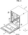
- FIG. 2 is a perspective view showing an opened state of a door, in a dishwasher according to an embodiment of the invention
- FIG. 3 is a cross-sectional view of the dishwasher shown in FIG. 1 , taken along line K-K'.
- a dishwasher 1 includes a main body 10 forming an outer appearance, a tub 20 provided inside the main body 10, and a door 30 for opening and closing the tub 20.
- the tub 20 may be substantially in a shape of a box having an open front side through which dishes are put into or taken out of the tub 20.
- a front opening of the tub 20 may be opened or closed by the door 30.
- the tub 20 includes a bottom plate 21, side walls, a upper wall 24, and a rear wall 25.
- the side walls may include a right wall (not shown) and a left wall 23.
- the door 30 may be rotatably mounted on the main body 10 to open or close the tub 20. More specifically, the door 30 may be rotatably mounted on the main body 10 to open or close the open front side of the tub 20.
- the door 30 may be rotatably coupled with the main body 10 by a door bracket 35.
- the door 30 may be rotatably coupled with the main body 10 by a pair of door brackets 35.
- the door 30 may include an outer door 31 forming a front outer appearance of the dishwasher 1, and an inner door 32 coupled with the outer door 31 in such a way as to face the tub 20. That is, the inner door 32 may be coupled with an inner surface of the outer door 31.
- the dishwasher 1 may further include a plurality of baskets 40 provided inside the tub 20 to accommodate dishes.
- the plurality of baskets 40 may be a wire rack made of wires that pass washing water without collecting the washing water therein.
- the plurality of baskets 40 may be detachably installed inside the tub 20.
- the plurality of baskets 40 may include a upper basket 41 positioned in an upper space of the tub 20, and a lower basket 42 positioned in a lower space of the tub 20.
- the dishwasher 1 may further include a plurality of spray nozzles 51, 52, and 53 for spraying washing water.
- the plurality of spray nozzles 51, 52, and 53 may spray washing water at high pressure to wash dishes.
- the plurality of spray nozzles 51, 52, and 53 may include a upper rotating nozzle 51 provided in the upper space of the tub 20, a middle rotating nozzle 52 provided in a center space of the tub 20, and a fixed nozzle 53 provided in the lower space of the tub 20.
- the upper rotating nozzle 51 may be provided above the upper basket 41, and spray washing water downward while rotating by water pressure. To spray washing water downward, a plurality of spray holes 52a may be formed in a lower end of the upper rotating nozzle 51. The upper rotating nozzle 51 may directly spray washing water toward dishes accommodated in the upper basket 41.
- the middle rotating nozzle 52 may be positioned between the upper basket 41 and the lower basket 42, and spray washing water in an up-down direction while rotating by water pressure. To spray washing water in the up-down direction, a plurality of spray holes 52a may be formed in each of upper and lower ends of the middle rotating nozzle 52. The middle rotating nozzle 52 may directly spray washing water toward dishes accommodated in the upper basket 41 and the lower basket 42.
- the fixed nozzle 53 may be immovable unlike the upper rotating nozzle 51 and the middle rotating nozzle 52, and fixed to one side of the tub 20.
- the fixed nozzle 53 may be positioned adjacent to the rear wall 25 of the tub 20 to spray washing water toward a front direction of the tub 20. Accordingly, washing water sprayed from the fixed nozzle 53 may not directly head toward dishes.
- the washing water sprayed from the fixed nozzle 53 may be reflected toward the dishes by a vein 60.
- the fixed nozzle 53 may be positioned below the lower basket 42, and the vein 60 may reflect washing water sprayed from the fixed nozzle 53 upward. That is, washing water sprayed from the fixed nozzle 53 may be reflected toward dishes accommodated in the lower basket 42 by the vein 60.
- the fixed nozzle 53 may have a plurality of spray holes 53a aligned in a left-right direction of the tub 20.
- the plurality of spray holes 53a may spray washing water toward the front direction.
- the upper rotating nozzle 51 and the middle rotating nozzle 52 may be coupled with and fixed to the fixing nozzle 53.
- the dishwasher 1 may further include the vein 60 moving inside the tub 20 and reflecting washing water toward the dishes, and a driving device 70 for driving the vein 60.
- the vein 60 may extend in the left-right direction of the tub 20 to reflect all washing water sprayed from the plurality of spray holes 53a of the fixed nozzle 53. That is, one end in longitudinal direction of the vein 60 may be adjacent to the left wall 23 of the tub 20, and the other end in longitudinal direction of the vein 60 may be adjacent to the right wall of the tub 20.
- the vein 60 may perform a linear reciprocating motion in a spray direction of washing water sprayed from the fixed nozzle 53. That is, the vein 60 may perform a linear reciprocating motion in a front-back direction of the tub 20. Accordingly, a linear spray structure including the fixed nozzle 53 and the vein 60 may wash the entire inside space of the tub 20 without making a blind spot.
- the dishwasher 1 may further include a sump 80 storing washing water, a circulating pump 93 for pumping the washing water stored in the sump 80 to supply the pumped washing water to the plurality of spray nozzles 51, 52, and 53, and a drain pump 95 for discharging washing water collected in the sump 80 to outside of the main body 10 together with wastes.
- the dishwasher 1 may further include a gasket 100 installed between the tub 20 and the door 30 to prevent leakage of washing water. That is, the dishwasher 1 may further include the gasket 100 for covering a gap between the tub 20 and the door 30 to prevent leakage of washing water.
- the gasket 100 may be made of an elastic material.
- the elastic material may include rubber, silicon, and the like.
- the gasket 100 includes a sealing member 110 positioned between a lower end of the door 30 and a lower end of the tub 20 to cover a gap between the lower end of the door 30 and the lower end of the tub 20. That is, the sealing member 110 is positioned between the lower end of the door 30 and the bottom plate 21 of the tub 20 to cover the gap between the lower end of the door 30 and the lower end of the tub 20. Details about the sealing member 110 will be described below.
- the gasket 100 may further include a packing member 120 installed to cover a gap between the door 30 and the tub 20, together with the sealing member 110.
- the packing member 120 may be installed on the tub 20 to cover the gap between the door 30 and the tub 20. More specifically, the packing member 120 may include a first packing member 121 installed on the side walls of the tub 20 to cover gaps between side ends of the door 30 and side ends of the tub 20, and a second packing member (not shown) installed on the upper wall 24 of the tub 20 to cover a gap between an upper end of the door 30 and a upper end of the tub 20.
- the first packing member 121 may extend from the side walls of the tub 20 to a portion of the bottom plate 21 being adjacent to the side walls of the tub 20.
- the first packing member 121 and the second packing member may be integrated into one body.
- the first packing member 121 and the second packing member may be not integrated into one body as long as the first packing member 121 is connected to the second packing member.
- the first packing member 121 and the second packing member may be manufactured separately, and then the first packing member 121 may be coupled with the second packing member.
- the dishwasher 1 further includes a cover member 200 for covering a gap between a lower end of the inner door 32 and the lower end of the tub 20 according to whether the inner door 32 is opened or closed, to prevent washing water from leaking out.
- the cover member 200 may complement the function of the gasket 100.
- the cover member 200 may prevent washing water moving in an unexpected direction while the dishwasher 1 operates from leaking out of the dishwasher 1.
- the cover member 200 may prevent leakage of washing water at a portion at which leakage of washing water is not prevented by the sealing member 110.
- the cover member 200 may prevent washing water from leaking out between a side portion of the inner door 32 and the bottom plate 21 of the tub 20.
- the cover member 200 may be coupled with the sealing member 110 and move together with the sealing member 110.
- the cover member 200 may be made of a flexible material. More preferably, the cover member 200 may be made of a flexible, elastic material. For example, the cover member 200 may be made of rubber, silicon, etc. The cover member 200 made of a flexible material may be easily adhered to the tub 20, and accordingly, the cover member 200 may effectively prevent washing water from leaking out of the dishwasher 1 according to closing of the door 30.
- the material of the cover member 200 is not limited to the above-mentioned example as long as the cover member 200 is capable of covering the gap between the lower end of the inner door 32 and the lower end of the tub 20.
- the cover member 200 may be made of a hard plastic material. Details about the cover member 200 will be described below.
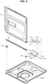
- FIG. 4 is a perspective view showing a door, a bottom plate of a tub, a sealing member, and a cover member, in a dishwasher according to an embodiment of the invention
- FIG. 5 is an exploded perspective view showing a coupling structure of the door, the bottom plate of the tub, the sealing member, and the cover member of FIG. 4 .
- the door 30 opens and closes the tub 20, and the inner door 32 is positioned inside the tub 20 upon closing of the tub 20 by the door 30.
- the sealing member 110 is positioned at the lower end of the door 30 to seal between the inner door 32 and the bottom (the bottom plate 21) of the tub 20 and thereby prevent washing water stored in the tub 20 from leaking between the inner door 32 and the bottom plate 21 of the tub 20.
- cover member 200 additionally covers the gap between the inner door 32 and the bottom plate 21 of the tub 20 to prevent leakage at a portion not sealed by the sealing member 110.
- cover member 200 may cover a gap between the sealing member 110 and the lower end of the inner door 32 to effectively prevent washing water from leaking out.
- the lower end of the inner door 32 includes a side panel 35, a first flange 37, and a second flange 39.
- the side panel 35 faces the side surface of the tub 20, and the first flange 37 extends along the lower end of the door 30 to face the bottom plate 21 of the tub 20. Also, the second flange 39 extends upward from the first flange 37.
- the first and second flanges 37 and 39 may be integrated into one body, or may be manufactured separately and then coupled with each other.
- the first flange 37 and the second flange 39 is formed, and the sealing member 110 and the cover member 200 is coupled with the first and second flanges 37 and 39 to prevent washing water from leaking out.
- the first and second flanges 37 and 39 is used to be coupled with the sealing member 110 and the cover member 200, wherein the sealing member 110 is coupled with the first and second flanges 37 and 39 to prevent leakage between the lower end of the inner door 32 and the bottom plate 21 of the tub 20, and the cover member 200 is coupled with the first and second flanges 37 and 39 or positioned in a space formed by the first and second flanges 37 and 39 to prevent leakage through a gap between the lower end of the inner door 32 and the sealing member 110.
- a first hole 38 with which the sealing member 110 is coupled may be formed at one side of the second flange 39, and the first hole 38 will be described below.
- FIG. 6 is a perspective view showing a state in which the cover member of FIG. 4 is coupled with the door
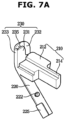
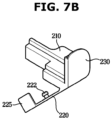
- FIGS. 7A and 7B are enlarged perspective views showing the cover member of FIG. 4
- FIG. 8 is a perspective view showing a state in which a sealing member is coupled with a door coupled with the cover member of FIG. 6
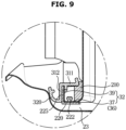
- FIG. 9 is a cross-sectional view taken along line A-A' of FIG. 4 .
- the cover member 200 may be coupled with or located at a side portion (the side panel 35) of the lower end of the inner door 32 before the sealing member 110 is coupled with the lower end of the inner door 32, and the sealing member 110 may be coupled with the second flange 39 after the cover member 200 is coupled with or located at the lower end of the inner door 32.
- the cover member 200 may be accommodated between the first flange 37 and the second flange 39 while being coupled with the side panel 35 of the inner door 32 to cover a space between the side surface of the inner door 32 and the lower end of the inner door 32.
- the cover member 200 includes a body portion 210, a first cover portion 230, and a second cover portion 220, wherein the body portion 210, the first cover portion 230, and the second cover portion 220 may be integrated into one body.
- the body portion 210 is positioned between the first flange 37 and the second flange 39.
- the first cover portion 230 is connected to the body portion 210, extend upward from the body portion 210, and is be- coupled with the side panel 35.
- the side panel 35 forms the side surface of the inner door 32, and be located at a preset height from the bottom plate 21 of the tub 20 to form a space in which the first cover member 230 is coupled with the side panel 35.
- the first cover portion 230 may include, as shown in FIG. 7A , a first plate 231, a second plate 232 facing the first plate 231, and a third plate 233 provided between the first plate 231 and the second plate 232. Accordingly, at the upper end of the first cover portion 230, the opening 235 may be formed by the first plate 231, the second plate 232, and the third plate 233.
- the body portion 210 is accommodated between the first flange 37 and the second flange 39 formed in the lower end of the inner door 32, and the first cover portion 230 is coupled with the side panel 35 of the door 30 to completely prevent washing water flowing along the bottom plate 21 of the tub 20 from leaking between the first and second flanges 37 and 39 and the side surface of the inner door 32.
- the body portion 210 may be inserted between the first flange 37 and the second flange 39 and fixed to prevent the cover member 200 from being separated from the lower end of the inner door 32.
- the second cover portion 220 is connected to one side of the body portion 210, and formed at a lower portion of the body portion 210.
- the second cover portion 220 is coupled with the first flange 37 in a case in which the body portion 210 is positioned between the first flange 37 and the second flange 39 as described above. That is, in a case in which the body portion 210 is positioned on one surface of the first flange 37, the second cover portion 220 is coupled with the other surface of the first flange 37.
- the first flange 37 may form a coupling hole 36
- the second cover portion 220 may form a protrusion 222 for coupling with the coupling hole 36 on a surface facing the first flange 37.
- the second cover portion 220 may be coupled with the first flange 37 by passing the protrusion 222 through the coupling hole 36 formed in the other surface of the first flange 37.
- the second cover portion 220 may be positioned between the first flange 37 and the bottom plate 21 of the tub 20 to cover a gap between the first flange 37 and the bottom plate 21 of the tub 20.
- the second cover member 220 may be, as shown in FIGS. 7A and 7B , connected to an end of the body portion 210, and extend downward from the body portion 210 in such a way as to form a preset angle with respect to the body portion 210. In this state, the second cover portion 220 may move upward to be coupled with the first flange 37.
- the second cover portion 220 may include a material having flexibility to easily move.
- the second cover portion 220 may include a protrusion rib 225 extending upward at one end, as shown in the drawings, and the protrusion rib 225 will be described below.
- the sealing member 110 may be coupled with or located at the lower end of the inner door 32, as shown in FIG. 8 .
- the sealing member 110 may be provided in the lower end of the inner door 32 in such a way as to be in contact with the bottom plate 21 of the tub 20, to prevent washing water from moving toward the lower end of the inner door 32 from the bottom plate 21 of the tub 20.
- the sealing member 110 may include a first sealing portion 310 and a second sealing portion 320.
- the first sealing portion 310 may have a cross section in a shape of ' ⁇ ', include a plastic material, and be coupled with the second flange 39.
- the second flange 39 may include the first hole 38
- the first sealing portion 310 may include a second hole 315 corresponding to the first hole 38.
- such mechanical coupling between the first sealing portion 310 and the second flange 39 may be performed after the cover member 200 is accommodated between the first flange 37 and the second flange 39.
- the first hole 38 of the second flange 39 may be formed at a portion being adjacent to the accommodated cover member 200, and to pass the mechanical coupling member through the first hole 38, the first hole 38 may be spaced a preset distance from the cover member 200 to form a space for mechanical coupling.
- the body portion 210 may include a first body member 212 inserted between the first flange 37 and the second flange 39, and a second body member 214 having a narrower width than the first body member 212 and spaced a preset distance from the second flange 39. That is, the second body member 214 may be positioned between the first flange 37 and the second flange 39 to form an empty space, and accordingly, the mechanical coupling member may pass through the second hole 315 of the first sealing portion 310 and the first hole 38 of the second flange 39 to be positioned in the empty space.
- the first sealing portion 310 may include a first seal 311 and a second seal 312.
- the first seal 311 may extend along the second flange 39 and be coupled with one side of the second flange 39. That is, the first seal 311 may include the first hole 38 and be coupled with the second hole 315 of the second flange 39 through the mechanical coupling member.
- the second seal 312 may extend from one end of the first seal 311 to face the first flange 37.
- the second seal 312 may include a guide rib 317 protruding on a surface facing the first flange 37.
- the second flange 39 may be inserted between the first seal 311 and the guide rib 317, and the first sealing portion 310 may be coupled with the inner door 32. That is, the first seal 311 may be coupled with one side of the second flange 39, and the guide rib 317 may be adhered to the other side of the second flange 39 to stably couple the first sealing portion 310 with the inner door 32.
- the second sealing portion 320 may be bent upward from one end of the first seal 311 to seal a gap between the bottom plate 21 of the tub 20 and the second flange 39.
- the second sealing portion 320 may seal a gap between the second flange 39 and a portion bent upward from the bottom plate 21 of the tub 20, and accordingly, washing water moving along the bottom plate 21 of the tub 20 may be prevented from leaking out above the bent portion.
- the second sealing portion 320 may be made of a rubber material, and accordingly, the second sealing portion 320 may be adhered to the bottom plate 21 of the tub 20, thereby performing sealing.
- the protrusion rib 225 of the second cover portion 220 may be inserted between the first seal 311 of the first sealing portion 310 and the second flange 39, as shown in FIG. 9 . That is, the protrusion rib 225 may extend upward from one side of the second cover portion 220, as described above, and may be insertion-coupled between the first seal 311 and the second flange 39 to more stably couple the cover member 200 with the lower end of the inner door 32.
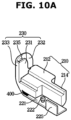
- FIG. 10 is a perspective view showing a cover member in a dishwasher according to another embodiment of the disclosure.
- a cover member 200 may have the same configuration as the cover member 200 described above with reference to FIGS. 6 and 7 , except that a second cover portion 221 is parallel to a body portion.
- the second cover portion 221 of the cover member 200 may be connected to an end of the body portion and extend parallel to the body portion.
- the cover member 200 may include an elastic member 400 having elasticity, wherein the elastic member 400 is formed between the second cover portion 221 and the body portion at a portion at which the second cover portion 221 is connected to the body portion.
- the sealing member 110 may be coupled with the lower end of the inner door 32 after the second cover portion 221 moves downward, and after the sealing member 110 is coupled with the lower end of the inner door 32, the second cover portion 221 may again move upward to couple the protrusion 222 with the first flange 37.
- the second cover portion 221 may be maintained in parallel to the body portion by the elastic member 400 to easily couple the second cover portion 221 with the first flange 371.
- the dishwasher according to a concept of the invention may prevent leakage by covering the gap between the inner door and the bottom of the tub.
- the dishwasher may prevent leakage at a portion that is not prevented from leakage by the sealing member by covering the gap between the inner door and the sealing member.
Landscapes
- Washing And Drying Of Tableware (AREA)
Claims (11)
- Geschirrspüler, umfassend:einen Hauptkörper (10);eine Wanne (20), die innerhalb des Hauptkörpers bereitgestellt ist, um einen Waschraum zu bilden;eine Tür (30), die konfiguriert ist, um die Wanne zu öffnen und zu schließen und eine Innentür (32) beinhaltet, die sich innerhalb der Wanne befindet, während die Wanne durch die Tür geschlossen ist,ein Dichtungselement (110), das an einem unteren Ende der Innentür bereitgestellt und konfiguriert ist, um zu verhindern, dass Auslaufen zwischen einer unteren Platte der Wanne und der Innentür stattfindet; undein Abdeckelement (200), das mit dem unteren Ende der Innentür gekoppelt ist oder sich daran befindet und um einen Spalt zwischen dem unteren Ende der Innentür und der Wanne abzudecken,wobei das untere Ende der Innentür Folgendes umfasst:ein Seitenpaneel (35), das gebildet ist, um einer Seitenfläche der Wanne zugewandt zu sein;einen ersten Flansch (37), der gebildet ist, um der unteren Platte der Wanne zugewandt zu sein; undeinen zweiten Flansch (39), der gebildet ist, um sich nach oben von dem ersten Flansch zu erstrecken, wenn die Tür geschlossen ist, und das Abdeckelement an das Seitenpaneel koppelbar ist,wobei das Dichtungselement Folgendes umfasst:einen ersten Dichtungsabschnitt (310), der an den zweiten Flansch koppelbar ist, undeinen zweiten Dichtungsabschnitt (320), der gebildet ist, um nach oben von dem ersten Dichtungsabschnitt gebogen zu sein, wenn die Tür geschlossen ist, und um einen Spalt zwischen der unteren Platte der Wanne und dem zweiten Flansch abzudichten, unddadurch gekennzeichnet, dass das Abdeckelement Folgendes umfasst:einen Körperabschnitt (210), der zwischen dem ersten Flansch und dem zweiten Flansch zu positionieren ist,einen ersten Abdeckabschnitt (230), der mit dem Körperabschnitt zu verbinden ist, gebildet ist, um sich nach oben zu erstrecken und an das Seitenpaneel koppelbar ist, undeinen zweiten Abdeckabschnitt (220), der mit einer Seite des Körperabschnittes zu verbinden ist, an den ersten Flansch koppelbar ist und zwischen der unteren Platte der Wanne und dem ersten Flansch positioniert ist.
- Geschirrspüler nach Anspruch 1, wobei der zweite Flansch (39) ein erstes Loch (38) umfasst, und
der erste Dichtungsabschnitt (310) ein zweites Loch (315) umfasst, das an einer Stelle gebildet ist, die dem ersten Loch entspricht. - Geschirrspüler nach Anspruch 1, wobei der erste Dichtungsabschnitt (310) Folgendes umfasst:eine erste Dichtung (311), die gebildet ist, um sich entlang des zweiten Flansches (39) zu erstrecken und an eine Seite des zweiten Flansches koppelbar ist, undeine zweite Dichtung (312), die gebildet ist, um sich von einem Ende der ersten Dichtung zu erstrecken, um dem ersten Flansch (37) zugewandt zu sein und eine Führungsrippe (317) beinhaltet, die an einer anderen Seite des zweiten Flansches haftet.
- Geschirrspüler nach Anspruch 1, wobei eine Öffnung (235) zum Aufnehmen eines Endes des Seitenpaneels an einem oberen Ende des ersten Abdeckabschnittes (230) gebildet ist.
- Geschirrspüler nach Anspruch 4, wobei der erste Abdeckabschnitt (230) Folgendes umfasst:eine erste Platte (231);eine zweite Platte (232), die gebildet ist, um der ersten Platte zugewandt zu sein; undeine dritte Platte (233), die zwischen der ersten Platte und der zweiten Platte bereitgestellt ist.
- Geschirrspüler nach Anspruch 1, wobei der erste Flansch (37) Folgendes umfasst:ein Kopplungsloch (36), undein Vorsprung (222) zum Koppeln mit dem Kopplungsloch auf einer Oberfläche des zweiten Abdeckabschnittes (220) gebildet ist, wobei die Oberfläche gebildet ist, um dem ersten Flansch zugewandt zu sein.
- Geschirrspüler nach Anspruch 6, wobei der zweite Abdeckabschnitt (220) eine vorspringende Rippe (225) umfasst, die gebildet ist, um zwischen dem ersten Dichtungsabschnitt (310) und dem zweiten Flansch (39) eingesetzt und befestigt zu sein, während der erste Dichtungsabschnitt an den zweiten Flansch gekoppelt ist.
- Geschirrspüler nach Anspruch 1, wobei der Körperabschnitt (210) Folgendes umfasst:ein erstes Körperelement (212), das gebildet ist, um zwischen dem ersten Flansch (37) und dem zweiten Flansch (39) eingesetzt zu sein; undein zweites Körperelement (214), das eine geringere Breite als das erste Körperelement aufweist und in einem voreingestellten Abstand von dem zweiten Flansch beabstandet ist.
- Geschirrspüler nach Anspruch 1, wobei der zweite Abdeckabschnitt (220) ein flexibles Material beinhaltet.
- Geschirrspüler nach Anspruch 9, wobei, während der zweite Abdeckabschnitt (220) mit einem Ende des Körperabschnittes (210) verbunden ist, der zweite Abdeckabschnitt einen voreingestellten Winkel in Bezug auf den Körperabschnitt bildet.
- Geschirrspüler nach Anspruch 9, wobei, während der zweite Abdeckabschnitt (220) mit einem Ende des Körperabschnittes (210) verbunden ist, sich der zweite Abdeckabschnitt parallel zu dem Körperabschnitt erstreckt.
Applications Claiming Priority (2)
| Application Number | Priority Date | Filing Date | Title |
|---|---|---|---|
| KR1020190106593A KR102766431B1 (ko) | 2019-08-29 | 2019-08-29 | 식기세척기 |
| PCT/KR2020/008533 WO2021040215A1 (ko) | 2019-08-29 | 2020-06-30 | 식기세척기 |
Publications (4)
| Publication Number | Publication Date |
|---|---|
| EP4000491A1 EP4000491A1 (de) | 2022-05-25 |
| EP4000491A4 EP4000491A4 (de) | 2022-09-28 |
| EP4000491B1 true EP4000491B1 (de) | 2024-10-16 |
| EP4000491C0 EP4000491C0 (de) | 2024-10-16 |
Family
ID=74684279
Family Applications (1)
| Application Number | Title | Priority Date | Filing Date |
|---|---|---|---|
| EP20856358.5A Active EP4000491B1 (de) | 2019-08-29 | 2020-06-30 | Geschirrspüler |
Country Status (4)
| Country | Link |
|---|---|
| US (1) | US12121196B2 (de) |
| EP (1) | EP4000491B1 (de) |
| KR (1) | KR102766431B1 (de) |
| WO (1) | WO2021040215A1 (de) |
Families Citing this family (4)
| Publication number | Priority date | Publication date | Assignee | Title |
|---|---|---|---|---|
| CN212307758U (zh) * | 2020-04-21 | 2021-01-08 | 佛山市顺德区美的洗涤电器制造有限公司 | 洗碗机 |
| KR20230018765A (ko) * | 2021-07-30 | 2023-02-07 | 삼성전자주식회사 | 식기 세척기 |
| EP4295740A4 (de) * | 2021-07-30 | 2024-08-14 | Samsung Electronics Co., Ltd. | Geschirrspülmaschine |
| WO2024005414A1 (ko) * | 2022-06-30 | 2024-01-04 | 삼성전자주식회사 | 식기 세척기 |
Family Cites Families (22)
| Publication number | Priority date | Publication date | Assignee | Title |
|---|---|---|---|---|
| JP3049214U (ja) * | 1997-11-27 | 1998-06-09 | 日本電熱株式会社 | 食器洗い乾燥機の開閉ドアシール |
| KR200215082Y1 (ko) | 1998-10-21 | 2001-03-02 | 윤홍구 | 식기세척기용 도어실패킹구조 |
| KR200269246Y1 (ko) * | 1999-06-24 | 2002-03-21 | 유병진 | 식기세척기용 캐비티 |
| DE19933700A1 (de) * | 1999-07-19 | 2001-01-25 | Bsh Bosch Siemens Hausgeraete | Geschirrspülmaschine |
| JP3666351B2 (ja) * | 2000-04-12 | 2005-06-29 | 松下電器産業株式会社 | 食器洗い機 |
| EP1281345A1 (de) | 2001-07-31 | 2003-02-05 | Bonferraro S.p.A. | Dichtung für eine Tür einer Geschirrspülmaschine |
| KR101287531B1 (ko) * | 2007-01-30 | 2013-07-18 | 삼성전자주식회사 | 식기세척기 |
| EP2224840B1 (de) * | 2007-12-27 | 2014-11-12 | Arçelik Anonim Sirketi | Dichtung für einen geschirrspüler |
| CN201346193Y (zh) * | 2009-01-13 | 2009-11-18 | 美的集团有限公司 | 一种用于洗碗机的门下挡水密封条 |
| EP2432365B1 (de) * | 2009-05-22 | 2016-09-07 | Arçelik Anonim Sirketi | Geschirrspülmaschine |
| DE102010063109B4 (de) * | 2010-12-15 | 2023-02-09 | BSH Hausgeräte GmbH | Geschirrspülmaschine mit einer Türdichtung |
| DE102011004085B4 (de) * | 2011-02-14 | 2016-09-22 | BSH Hausgeräte GmbH | Geschirrspülmaschine mit einer beweglichen Tür und zumindest einer Türdichtung |
| DE102011004088A1 (de) * | 2011-02-14 | 2012-08-16 | BSH Bosch und Siemens Hausgeräte GmbH | Geschirrspülmaschine mit einer beweglichen Tür und zumindest einer Türdichtung |
| DE102011004087A1 (de) * | 2011-02-14 | 2012-08-16 | BSH Bosch und Siemens Hausgeräte GmbH | Geschirrspülmaschine mit einer beweglichen Tür und zumindest einer Türdichtung |
| DE102011004089B4 (de) * | 2011-02-14 | 2016-10-06 | BSH Hausgeräte GmbH | Geschirrspülmaschine mit einer beweglichen Tür und zumindest einer Türdichtung |
| DE102012202264B4 (de) * | 2012-02-15 | 2016-10-27 | BSH Hausgeräte GmbH | Geschirrspülmaschine mit einer unteren Türquerdichtung |
| KR102046052B1 (ko) * | 2013-11-06 | 2019-11-18 | 삼성전자주식회사 | 실링부재 및 이를 포함하는 식기세척기 |
| KR102396857B1 (ko) | 2015-06-02 | 2022-05-12 | 삼성전자주식회사 | 초음파 세척 기능을 구비한 세척장치 |
| KR102491972B1 (ko) * | 2016-06-13 | 2023-01-26 | 엘지전자 주식회사 | 식기 세척기 |
| KR20180060506A (ko) * | 2016-11-29 | 2018-06-07 | 엘지전자 주식회사 | 식기 세척기 |
| CN107981819B (zh) * | 2017-12-29 | 2023-09-15 | 珠海格力电器股份有限公司 | 一种门下密封条及洗碗机 |
| KR102662674B1 (ko) * | 2019-02-01 | 2024-05-03 | 삼성전자주식회사 | 식기세척기 |
-
2019
- 2019-08-29 KR KR1020190106593A patent/KR102766431B1/ko active Active
-
2020
- 2020-06-30 WO PCT/KR2020/008533 patent/WO2021040215A1/ko not_active Ceased
- 2020-06-30 EP EP20856358.5A patent/EP4000491B1/de active Active
-
2022
- 2022-02-28 US US17/682,303 patent/US12121196B2/en active Active
Also Published As
| Publication number | Publication date |
|---|---|
| KR20210026166A (ko) | 2021-03-10 |
| EP4000491C0 (de) | 2024-10-16 |
| EP4000491A1 (de) | 2022-05-25 |
| EP4000491A4 (de) | 2022-09-28 |
| KR102766431B1 (ko) | 2025-02-12 |
| WO2021040215A1 (ko) | 2021-03-04 |
| US12121196B2 (en) | 2024-10-22 |
| US20220183535A1 (en) | 2022-06-16 |
Similar Documents
| Publication | Publication Date | Title |
|---|---|---|
| EP4000491B1 (de) | Geschirrspüler | |
| KR102822721B1 (ko) | 식기세척기 | |
| US9782052B2 (en) | Nozzle assembly and dishwasher having the same | |
| US6622896B2 (en) | Dishwasher detergent dispenser | |
| KR102854972B1 (ko) | 세제공급장치 및 이를 포함하는 세탁기 | |
| KR101054115B1 (ko) | 식기 세척기의 도어 실링 개스킷 구조 | |
| KR20170057952A (ko) | 세탁기 | |
| KR101776629B1 (ko) | 식기세척기 | |
| KR20180060506A (ko) | 식기 세척기 | |
| KR102491972B1 (ko) | 식기 세척기 | |
| US20220142450A1 (en) | Dishwasher | |
| US8118947B2 (en) | Sealing device for a dishwasher, and associated apparatus and method | |
| KR102662674B1 (ko) | 식기세척기 | |
| US11744435B2 (en) | Dishwasher | |
| EP2529655A1 (de) | Geschirrspülmaschine | |
| KR102334623B1 (ko) | 식기 세척기 | |
| KR19980082399A (ko) | 식기세척기의 소음누설 차단장치 | |
| JP4609367B2 (ja) | 食器洗い機 | |
| KR20180025735A (ko) | 식기 세척기 | |
| KR100239518B1 (ko) | 식기세척기의 소음누설 차단장치 | |
| KR100399326B1 (ko) | 서랍식 식기 세척기의 밀폐 구조 | |
| KR101290357B1 (ko) | 식기 세척기 | |
| JP4635946B2 (ja) | 食器洗い機 | |
| JP2025122321A (ja) | 食器洗い機 | |
| KR101257507B1 (ko) | 식기 세척기 |
Legal Events
| Date | Code | Title | Description |
|---|---|---|---|
| STAA | Information on the status of an ep patent application or granted ep patent |
Free format text: STATUS: THE INTERNATIONAL PUBLICATION HAS BEEN MADE |
|
| PUAI | Public reference made under article 153(3) epc to a published international application that has entered the european phase |
Free format text: ORIGINAL CODE: 0009012 |
|
| STAA | Information on the status of an ep patent application or granted ep patent |
Free format text: STATUS: REQUEST FOR EXAMINATION WAS MADE |
|
| 17P | Request for examination filed |
Effective date: 20220217 |
|
| AK | Designated contracting states |
Kind code of ref document: A1 Designated state(s): AL AT BE BG CH CY CZ DE DK EE ES FI FR GB GR HR HU IE IS IT LI LT LU LV MC MK MT NL NO PL PT RO RS SE SI SK SM TR |
|
| A4 | Supplementary search report drawn up and despatched |
Effective date: 20220829 |
|
| RIC1 | Information provided on ipc code assigned before grant |
Ipc: A47L 15/42 20060101AFI20220823BHEP |
|
| DAV | Request for validation of the european patent (deleted) | ||
| DAX | Request for extension of the european patent (deleted) | ||
| GRAP | Despatch of communication of intention to grant a patent |
Free format text: ORIGINAL CODE: EPIDOSNIGR1 |
|
| STAA | Information on the status of an ep patent application or granted ep patent |
Free format text: STATUS: GRANT OF PATENT IS INTENDED |
|
| INTG | Intention to grant announced |
Effective date: 20240624 |
|
| GRAS | Grant fee paid |
Free format text: ORIGINAL CODE: EPIDOSNIGR3 |
|
| GRAA | (expected) grant |
Free format text: ORIGINAL CODE: 0009210 |
|
| STAA | Information on the status of an ep patent application or granted ep patent |
Free format text: STATUS: THE PATENT HAS BEEN GRANTED |
|
| AK | Designated contracting states |
Kind code of ref document: B1 Designated state(s): AL AT BE BG CH CY CZ DE DK EE ES FI FR GB GR HR HU IE IS IT LI LT LU LV MC MK MT NL NO PL PT RO RS SE SI SK SM TR |
|
| REG | Reference to a national code |
Ref country code: GB Ref legal event code: FG4D |
|
| REG | Reference to a national code |
Ref country code: CH Ref legal event code: EP Ref country code: DE Ref legal event code: R096 Ref document number: 602020039695 Country of ref document: DE |
|
| REG | Reference to a national code |
Ref country code: IE Ref legal event code: FG4D |
|
| U01 | Request for unitary effect filed |
Effective date: 20241031 |
|
| U07 | Unitary effect registered |
Designated state(s): AT BE BG DE DK EE FI FR IT LT LU LV MT NL PT RO SE SI Effective date: 20241112 |
|
| PG25 | Lapsed in a contracting state [announced via postgrant information from national office to epo] |
Ref country code: HR Free format text: LAPSE BECAUSE OF FAILURE TO SUBMIT A TRANSLATION OF THE DESCRIPTION OR TO PAY THE FEE WITHIN THE PRESCRIBED TIME-LIMIT Effective date: 20241016 Ref country code: IS Free format text: LAPSE BECAUSE OF FAILURE TO SUBMIT A TRANSLATION OF THE DESCRIPTION OR TO PAY THE FEE WITHIN THE PRESCRIBED TIME-LIMIT Effective date: 20250216 |
|
| PG25 | Lapsed in a contracting state [announced via postgrant information from national office to epo] |
Ref country code: ES Free format text: LAPSE BECAUSE OF FAILURE TO SUBMIT A TRANSLATION OF THE DESCRIPTION OR TO PAY THE FEE WITHIN THE PRESCRIBED TIME-LIMIT Effective date: 20241016 |
|
| PG25 | Lapsed in a contracting state [announced via postgrant information from national office to epo] |
Ref country code: NO Free format text: LAPSE BECAUSE OF FAILURE TO SUBMIT A TRANSLATION OF THE DESCRIPTION OR TO PAY THE FEE WITHIN THE PRESCRIBED TIME-LIMIT Effective date: 20250116 |
|
| PG25 | Lapsed in a contracting state [announced via postgrant information from national office to epo] |
Ref country code: GR Free format text: LAPSE BECAUSE OF FAILURE TO SUBMIT A TRANSLATION OF THE DESCRIPTION OR TO PAY THE FEE WITHIN THE PRESCRIBED TIME-LIMIT Effective date: 20250117 |
|
| PG25 | Lapsed in a contracting state [announced via postgrant information from national office to epo] |
Ref country code: PL Free format text: LAPSE BECAUSE OF FAILURE TO SUBMIT A TRANSLATION OF THE DESCRIPTION OR TO PAY THE FEE WITHIN THE PRESCRIBED TIME-LIMIT Effective date: 20241016 |
|
| PG25 | Lapsed in a contracting state [announced via postgrant information from national office to epo] |
Ref country code: RS Free format text: LAPSE BECAUSE OF FAILURE TO SUBMIT A TRANSLATION OF THE DESCRIPTION OR TO PAY THE FEE WITHIN THE PRESCRIBED TIME-LIMIT Effective date: 20250116 |
|
| PG25 | Lapsed in a contracting state [announced via postgrant information from national office to epo] |
Ref country code: SM Free format text: LAPSE BECAUSE OF FAILURE TO SUBMIT A TRANSLATION OF THE DESCRIPTION OR TO PAY THE FEE WITHIN THE PRESCRIBED TIME-LIMIT Effective date: 20241016 |
|
| PG25 | Lapsed in a contracting state [announced via postgrant information from national office to epo] |
Ref country code: SK Free format text: LAPSE BECAUSE OF FAILURE TO SUBMIT A TRANSLATION OF THE DESCRIPTION OR TO PAY THE FEE WITHIN THE PRESCRIBED TIME-LIMIT Effective date: 20241016 |
|
| PG25 | Lapsed in a contracting state [announced via postgrant information from national office to epo] |
Ref country code: CZ Free format text: LAPSE BECAUSE OF FAILURE TO SUBMIT A TRANSLATION OF THE DESCRIPTION OR TO PAY THE FEE WITHIN THE PRESCRIBED TIME-LIMIT Effective date: 20241016 |
|
| U20 | Renewal fee for the european patent with unitary effect paid |
Year of fee payment: 6 Effective date: 20250624 |
|
| PLBE | No opposition filed within time limit |
Free format text: ORIGINAL CODE: 0009261 |
|
| STAA | Information on the status of an ep patent application or granted ep patent |
Free format text: STATUS: NO OPPOSITION FILED WITHIN TIME LIMIT |
|
| 26N | No opposition filed |
Effective date: 20250717 |
|
| REG | Reference to a national code |
Ref country code: CH Ref legal event code: H13 Free format text: ST27 STATUS EVENT CODE: U-0-0-H10-H13 (AS PROVIDED BY THE NATIONAL OFFICE) Effective date: 20260127 |
|
| PG25 | Lapsed in a contracting state [announced via postgrant information from national office to epo] |
Ref country code: MC Free format text: LAPSE BECAUSE OF FAILURE TO SUBMIT A TRANSLATION OF THE DESCRIPTION OR TO PAY THE FEE WITHIN THE PRESCRIBED TIME-LIMIT Effective date: 20241016 |
|
| GBPC | Gb: european patent ceased through non-payment of renewal fee |
Effective date: 20250630 |
|
| PG25 | Lapsed in a contracting state [announced via postgrant information from national office to epo] |
Ref country code: GB Free format text: LAPSE BECAUSE OF NON-PAYMENT OF DUE FEES Effective date: 20250630 |
|
| PG25 | Lapsed in a contracting state [announced via postgrant information from national office to epo] |
Ref country code: IE Free format text: LAPSE BECAUSE OF NON-PAYMENT OF DUE FEES Effective date: 20250630 |
|
| PG25 | Lapsed in a contracting state [announced via postgrant information from national office to epo] |
Ref country code: CH Free format text: LAPSE BECAUSE OF NON-PAYMENT OF DUE FEES Effective date: 20250630 |