EP4000559B1 - Dispositif d'annuloplastie - Google Patents
Dispositif d'annuloplastie Download PDFInfo
- Publication number
- EP4000559B1 EP4000559B1 EP20207665.9A EP20207665A EP4000559B1 EP 4000559 B1 EP4000559 B1 EP 4000559B1 EP 20207665 A EP20207665 A EP 20207665A EP 4000559 B1 EP4000559 B1 EP 4000559B1
- Authority
- EP
- European Patent Office
- Prior art keywords
- stent
- annuloplasty device
- retention units
- support ring
- support
- Prior art date
- Legal status (The legal status is an assumption and is not a legal conclusion. Google has not performed a legal analysis and makes no representation as to the accuracy of the status listed.)
- Active
Links
Images






Classifications
-
- A—HUMAN NECESSITIES
- A61—MEDICAL OR VETERINARY SCIENCE; HYGIENE
- A61F—FILTERS IMPLANTABLE INTO BLOOD VESSELS; PROSTHESES; DEVICES PROVIDING PATENCY TO, OR PREVENTING COLLAPSING OF, TUBULAR STRUCTURES OF THE BODY, e.g. STENTS; ORTHOPAEDIC, NURSING OR CONTRACEPTIVE DEVICES; FOMENTATION; TREATMENT OR PROTECTION OF EYES OR EARS; BANDAGES, DRESSINGS OR ABSORBENT PADS; FIRST-AID KITS
- A61F2/00—Filters implantable into blood vessels; Prostheses, i.e. artificial substitutes or replacements for parts of the body; Appliances for connecting them with the body; Devices providing patency to, or preventing collapsing of, tubular structures of the body, e.g. stents
- A61F2/02—Prostheses implantable into the body
- A61F2/24—Heart valves ; Vascular valves, e.g. venous valves; Heart implants, e.g. passive devices for improving the function of the native valve or the heart muscle; Transmyocardial revascularisation [TMR] devices; Valves implantable in the body
- A61F2/2442—Annuloplasty rings or inserts for correcting the valve shape; Implants for improving the function of a native heart valve
- A61F2/2445—Annuloplasty rings in direct contact with the valve annulus
-
- A—HUMAN NECESSITIES
- A61—MEDICAL OR VETERINARY SCIENCE; HYGIENE
- A61B—DIAGNOSIS; SURGERY; IDENTIFICATION
- A61B17/00—Surgical instruments, devices or methods
- A61B17/064—Surgical staples, i.e. penetrating the tissue
-
- A—HUMAN NECESSITIES
- A61—MEDICAL OR VETERINARY SCIENCE; HYGIENE
- A61F—FILTERS IMPLANTABLE INTO BLOOD VESSELS; PROSTHESES; DEVICES PROVIDING PATENCY TO, OR PREVENTING COLLAPSING OF, TUBULAR STRUCTURES OF THE BODY, e.g. STENTS; ORTHOPAEDIC, NURSING OR CONTRACEPTIVE DEVICES; FOMENTATION; TREATMENT OR PROTECTION OF EYES OR EARS; BANDAGES, DRESSINGS OR ABSORBENT PADS; FIRST-AID KITS
- A61F2/00—Filters implantable into blood vessels; Prostheses, i.e. artificial substitutes or replacements for parts of the body; Appliances for connecting them with the body; Devices providing patency to, or preventing collapsing of, tubular structures of the body, e.g. stents
- A61F2/02—Prostheses implantable into the body
- A61F2/24—Heart valves ; Vascular valves, e.g. venous valves; Heart implants, e.g. passive devices for improving the function of the native valve or the heart muscle; Transmyocardial revascularisation [TMR] devices; Valves implantable in the body
- A61F2/2442—Annuloplasty rings or inserts for correcting the valve shape; Implants for improving the function of a native heart valve
- A61F2/2445—Annuloplasty rings in direct contact with the valve annulus
- A61F2/2448—D-shaped rings
-
- A—HUMAN NECESSITIES
- A61—MEDICAL OR VETERINARY SCIENCE; HYGIENE
- A61B—DIAGNOSIS; SURGERY; IDENTIFICATION
- A61B17/00—Surgical instruments, devices or methods
- A61B17/00234—Surgical instruments, devices or methods for minimally invasive surgery
- A61B2017/00238—Type of minimally invasive operation
- A61B2017/00243—Type of minimally invasive operation cardiac
-
- A—HUMAN NECESSITIES
- A61—MEDICAL OR VETERINARY SCIENCE; HYGIENE
- A61B—DIAGNOSIS; SURGERY; IDENTIFICATION
- A61B17/00—Surgical instruments, devices or methods
- A61B17/064—Surgical staples, i.e. penetrating the tissue
- A61B2017/0641—Surgical staples, i.e. penetrating the tissue having at least three legs as part of one single body
-
- A—HUMAN NECESSITIES
- A61—MEDICAL OR VETERINARY SCIENCE; HYGIENE
- A61F—FILTERS IMPLANTABLE INTO BLOOD VESSELS; PROSTHESES; DEVICES PROVIDING PATENCY TO, OR PREVENTING COLLAPSING OF, TUBULAR STRUCTURES OF THE BODY, e.g. STENTS; ORTHOPAEDIC, NURSING OR CONTRACEPTIVE DEVICES; FOMENTATION; TREATMENT OR PROTECTION OF EYES OR EARS; BANDAGES, DRESSINGS OR ABSORBENT PADS; FIRST-AID KITS
- A61F2/00—Filters implantable into blood vessels; Prostheses, i.e. artificial substitutes or replacements for parts of the body; Appliances for connecting them with the body; Devices providing patency to, or preventing collapsing of, tubular structures of the body, e.g. stents
- A61F2/82—Devices providing patency to, or preventing collapsing of, tubular structures of the body, e.g. stents
- A61F2/848—Devices providing patency to, or preventing collapsing of, tubular structures of the body, e.g. stents having means for fixation to the vessel wall, e.g. barbs
- A61F2002/8483—Barbs
-
- A—HUMAN NECESSITIES
- A61—MEDICAL OR VETERINARY SCIENCE; HYGIENE
- A61F—FILTERS IMPLANTABLE INTO BLOOD VESSELS; PROSTHESES; DEVICES PROVIDING PATENCY TO, OR PREVENTING COLLAPSING OF, TUBULAR STRUCTURES OF THE BODY, e.g. STENTS; ORTHOPAEDIC, NURSING OR CONTRACEPTIVE DEVICES; FOMENTATION; TREATMENT OR PROTECTION OF EYES OR EARS; BANDAGES, DRESSINGS OR ABSORBENT PADS; FIRST-AID KITS
- A61F2210/00—Particular material properties of prostheses classified in groups A61F2/00 - A61F2/26 or A61F2/82 or A61F9/00 or A61F11/00 or subgroups thereof
- A61F2210/0014—Particular material properties of prostheses classified in groups A61F2/00 - A61F2/26 or A61F2/82 or A61F9/00 or A61F11/00 or subgroups thereof using shape memory or superelastic materials, e.g. nitinol
-
- A—HUMAN NECESSITIES
- A61—MEDICAL OR VETERINARY SCIENCE; HYGIENE
- A61F—FILTERS IMPLANTABLE INTO BLOOD VESSELS; PROSTHESES; DEVICES PROVIDING PATENCY TO, OR PREVENTING COLLAPSING OF, TUBULAR STRUCTURES OF THE BODY, e.g. STENTS; ORTHOPAEDIC, NURSING OR CONTRACEPTIVE DEVICES; FOMENTATION; TREATMENT OR PROTECTION OF EYES OR EARS; BANDAGES, DRESSINGS OR ABSORBENT PADS; FIRST-AID KITS
- A61F2210/00—Particular material properties of prostheses classified in groups A61F2/00 - A61F2/26 or A61F2/82 or A61F9/00 or A61F11/00 or subgroups thereof
- A61F2210/0076—Particular material properties of prostheses classified in groups A61F2/00 - A61F2/26 or A61F2/82 or A61F9/00 or A61F11/00 or subgroups thereof multilayered, e.g. laminated structures
-
- A—HUMAN NECESSITIES
- A61—MEDICAL OR VETERINARY SCIENCE; HYGIENE
- A61F—FILTERS IMPLANTABLE INTO BLOOD VESSELS; PROSTHESES; DEVICES PROVIDING PATENCY TO, OR PREVENTING COLLAPSING OF, TUBULAR STRUCTURES OF THE BODY, e.g. STENTS; ORTHOPAEDIC, NURSING OR CONTRACEPTIVE DEVICES; FOMENTATION; TREATMENT OR PROTECTION OF EYES OR EARS; BANDAGES, DRESSINGS OR ABSORBENT PADS; FIRST-AID KITS
- A61F2220/00—Fixations or connections for prostheses classified in groups A61F2/00 - A61F2/26 or A61F2/82 or A61F9/00 or A61F11/00 or subgroups thereof
- A61F2220/0008—Fixation appliances for connecting prostheses to the body
- A61F2220/0016—Fixation appliances for connecting prostheses to the body with sharp anchoring protrusions, e.g. barbs, pins, spikes
-
- A—HUMAN NECESSITIES
- A61—MEDICAL OR VETERINARY SCIENCE; HYGIENE
- A61F—FILTERS IMPLANTABLE INTO BLOOD VESSELS; PROSTHESES; DEVICES PROVIDING PATENCY TO, OR PREVENTING COLLAPSING OF, TUBULAR STRUCTURES OF THE BODY, e.g. STENTS; ORTHOPAEDIC, NURSING OR CONTRACEPTIVE DEVICES; FOMENTATION; TREATMENT OR PROTECTION OF EYES OR EARS; BANDAGES, DRESSINGS OR ABSORBENT PADS; FIRST-AID KITS
- A61F2220/00—Fixations or connections for prostheses classified in groups A61F2/00 - A61F2/26 or A61F2/82 or A61F9/00 or A61F11/00 or subgroups thereof
- A61F2220/0025—Connections or couplings between prosthetic parts, e.g. between modular parts; Connecting elements
-
- A—HUMAN NECESSITIES
- A61—MEDICAL OR VETERINARY SCIENCE; HYGIENE
- A61F—FILTERS IMPLANTABLE INTO BLOOD VESSELS; PROSTHESES; DEVICES PROVIDING PATENCY TO, OR PREVENTING COLLAPSING OF, TUBULAR STRUCTURES OF THE BODY, e.g. STENTS; ORTHOPAEDIC, NURSING OR CONTRACEPTIVE DEVICES; FOMENTATION; TREATMENT OR PROTECTION OF EYES OR EARS; BANDAGES, DRESSINGS OR ABSORBENT PADS; FIRST-AID KITS
- A61F2220/00—Fixations or connections for prostheses classified in groups A61F2/00 - A61F2/26 or A61F2/82 or A61F9/00 or A61F11/00 or subgroups thereof
- A61F2220/0025—Connections or couplings between prosthetic parts, e.g. between modular parts; Connecting elements
- A61F2220/0033—Connections or couplings between prosthetic parts, e.g. between modular parts; Connecting elements made by longitudinally pushing a protrusion into a complementary-shaped recess, e.g. held by friction fit
-
- A—HUMAN NECESSITIES
- A61—MEDICAL OR VETERINARY SCIENCE; HYGIENE
- A61F—FILTERS IMPLANTABLE INTO BLOOD VESSELS; PROSTHESES; DEVICES PROVIDING PATENCY TO, OR PREVENTING COLLAPSING OF, TUBULAR STRUCTURES OF THE BODY, e.g. STENTS; ORTHOPAEDIC, NURSING OR CONTRACEPTIVE DEVICES; FOMENTATION; TREATMENT OR PROTECTION OF EYES OR EARS; BANDAGES, DRESSINGS OR ABSORBENT PADS; FIRST-AID KITS
- A61F2230/00—Geometry of prostheses classified in groups A61F2/00 - A61F2/26 or A61F2/82 or A61F9/00 or A61F11/00 or subgroups thereof
- A61F2230/0063—Three-dimensional shapes
- A61F2230/0091—Three-dimensional shapes helically-coiled or spirally-coiled, i.e. having a 2-D spiral cross-section
Definitions
- WO 2019/223975 A1 discloses an annuloplasty device comprising first and second support rings being configured to be arranged as a coil in a first configuration around an axial direction, wherein the first and second support rings are configured to be arranged on opposite sides of native heart valve leaflets of a heart valve, a stiffening unit, wherein at least part of the first and second support rings comprises an interior channel configured to receive the stiffening unit, wherein insertion of the stiffening unit into the interior channel increases the stiffness of the first and/or second support rings.
- EP3476366A1 discloses an annuloplasty implant comprising first and second supports.
- the supports have retention units to provide a retention force on either side of the heart valve.
- the supports may be formed from a solid rod, a hollow tube, or from a stent.
- the retention units 104, 104' may be flexible to bend from the expanded state (p 2 ) to the retracted state (p 1 ). This allows also for the retention units 104, 104', to flex to the retracted state (p 1 ) if withdrawing the annuloplasty device 100 into a delivery catheter, in case the implantation is aborted or repositioning is needed.
- the annuloplasty device 100 may thus re-assume the compact cross-sectional profile.
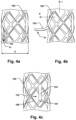
- the retention units 104, 104' may be aligned essentially flush with an outer diameter (D) of the stent 105 in the retracted state (p 1 ), as schematically illustrated in Fig. 4a or 4d .
- D outer diameter
- p 1 retracted state
- This provides for a compact cross-sectional profile of the annuloplasty device 100 as well as reduced risk of high pressure and abrasion of the retention units 104, 104', against an inner lumen of a delivery catheter.
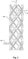
- the stent 105 may be radially contractible along a radial direction (R), perpendicular to a longitudinal direction (L) of the stent 105, so that the stent 105 exerts a force (F) on the first and/or second support ring 101, 102.
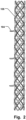
- the radial (R) and longitudinal direction (L) of the stent 105 is schematically indicated in Fig. 3 .
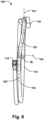
- the examples illustrated in Figs. 5a-b are cross-sectional views of the annuloplasty device 100, illustrating the stent 105 arranged around the first- or second support ring 101, 102, and a retention unit 104 in the expanded state (p 2 ).
- the stent 105 may thus be radially contractible towards the first and/or second support ring 101, 102, thereby exerting a force (F) onto the latter as indicated with arrows F in the illustrations of Figs. 5a-b .
- the stent 105 may thus assume a fixed position in relation to the first and/or second support ring 101, 102, as the force (F) creates friction between the stent 105 and the first and/or second support ring 101, 102.
- the framework of the stent 105 may thus be cut to allow movement in the radial direction (R), i.e.
- the stent 105 may be resiliently expandable in the radial direction (R) so that the stent 105 may be expanded to a radially stretched state.
- the stent 105 may then strive towards a contracted relaxed state with an inner diameter being less than the inner diameter in the radially stretched state.
- the inner diameter in the radially stretched state may be denoted d s (see e.g. Fig.
- stent 105 may be more or equal to an outer diameter (d r ) of first and/or second support ring 101, 102.
- the stent 105 may thus be positioned over the first and/or second support ring 101, 102, when in the radially stretched state.
- the stent 105 will thus strive towards the contracted relaxed state with a reduced inner diameter, and accordingly exert the aforementioned force (F) on the first and/or second support ring 101, 102.
- F aforementioned force
- This provides for a facilitated fixation of the position of the stent 105 in relation to the first and/or second support ring 101, 102.
- the example in Fig. 5a shows a cover 106 between the stent 105 and the first and/or second support ring 101, 102, as described in more detail below. The difference between d r and d s is thus larger in this case.
- the stent 105 may comprise a shape-memory material in one example. Activation of the shape-memory material may cause the stent 105 to contract to a reduced diameter, along the radial direction R, to apply a force (F) on the first and/or second support ring 101, 102.
- the shape-memory material may be temperature activated, so that the stent 105 strives towards a reduced inner diameter when subject to heating to the body temperature. This provides for increasing the force (F) exerted on the first and/or second support ring 101, 102, to attain a secure fixation of the stent 105 thereto.
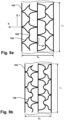
- Figs. 8a-b and 9a-b show examples of a radially contractible and expandable stent 105.
- the stent 105 may comprise support elements 108 configured to be contractible and expandable so that an outer diameter (D 1 , D 2 ) of the stent 105 is variable between an expanded diameter (D 1 ) and a contracted diameter (D 2 ) while a predefined length (L 1 ) of the stent 105 is essentially maintained.
- the overall length (L 1 ) of the stent 105 may be fixed.
- the stent 105 thus exhibit limited or no contraction in the longitudinal direction (L) as the diameter (D 1 , D 2 ) varies.
- the stent 105 may be expanded to D 1 and positioned on the first and/or second support ring 101, 102, and subsequently retracted to D 2 to apply a force radially inwards and thereby fix its position on the first and/or second support ring 101, 102, while undergoing no or insignificant variations in the length (L 1 ) of the stent 105.
- This provides for a facilitated and more accurate positioning of the stent 105 on the first and/or second support ring 101, 102.
- the tailoring of the stent 105 to first and second support rings 101, 102, of different dimensions is thus facilitated as the position and coverage of the stent 105 over the first and/or second support ring 101, 102, can be predicted with improved accuracy.
- the ratio between the movement in the radial direction (R) and the movement in the longitudinal direction (L) may for example be in the range 5:1 to 10:1 for a particularly advantageous and improved fixation of the stent 105 on the first and/or second support ring 101, 102. It is conceivable that the support elements 108 may be curved in different shapes to allow the radial movement as described, such as C-shapes or Z-shapes.
- Figs. 9a-b show an example where the support elements 108 are curved in bow-shapes.
- the bow-shaped support elements 108, or the S-shaped support elements 108 may be arranged to form an essentially cylindrical shape of the stent 105.
- the support elements 108 may thus extend generally across a surface of such cylindrical shape.
- the bow-shaped support elements 108 may be stretched when applying a force in the radial direction (R) so that the stent 105 may assume the expanded diameter (D 1 ) in Fig. 9a .
- the bow-shaped support elements 108 may contract again so that the stent 105 may assume the contracted diameter (D 2 ) in Fig. 9b .
- the support elements 108 may comprise an elongated main frame 121 extending essentially along the longitudinal direction (L) of the stent 105.
- the elongated main frame 121 may define the aforementioned predefined length (L 1 ) of the stent 105.
- the elongated main frame 121 may thus have an essentially fixed position in the longitudinal direction (L) when the outer diameter of the stent 105 varies between the expanded diameter (D 1 ) and the contracted diameter (D 2 ). This provides for effectively controlling the length of the stent 105 in the longitudinal direction (L).
- Figs. 10a-d show examples of the stent 105 having different support elements 108 and retention units 104.
- Figs. 10a-b show an example where the support elements 108 are S-shaped.
- the retention units 104 may be shaped as expandable bows, as described above, and schematically illustrated in Fig. 10a .
- a retracted state (p 1 ) is shown, as well as an expanded state (p 2 ) where the bows are illustrated with dashed lines.
- the retention unit 104 may be part of the support elements 108 as described in relation to Figs. 4d-e .
- the support elements 108 may comprise an elongated main frame 121. In the latter case, the retention unit 104 may be part of the elongated main frame 121.
- Fig. 10b show an example where the retention units 104 may be shaped as expandable prongs or hook-like structures.
- a retracted state (p 1 ) is shown, as well as an expanded state (p 2 ) where the prongs or hook-like structures are illustrated with dashed lines.
- Figs. 10c-d illustrate further examples where the bow-like ( Figs. 10c ) or hook-like ( Fig. 10d ) retention units 104 are arranged on bow-like support elements 108 of a stent 105.
- a retracted state (p 1 ) is shown, as well as an expanded state (p 2 ).
- the retention units 104 may be movable between the retracted state (p 1 ) and the expanded state (p 2 ) when the stent 105 has the contracted outer diameter (D 2 ), e.g. when fixed to the first and/or second support ring 101, 102, in order to anchor the stent 105 into the valve tissue.
- the annuloplasty device 100 may comprise a cover 106 arranged around at least a portion of the first and/or second support ring 101, 102.
- the cover 106 may be configured to promote endothelialization and the ingrowth of cells over the annuloplasty device 100.
- the cover 106 may have a surface which is more porous than the surface of the first- and second support rings 101, 102, which promotes the growth of cells over the annuloplasty device 100.
- the cover 106 may comprise a weave of a textile or a polymer.
- the stent 105 may be arranged around at least a portion of the cover 106.
- the cover 106 may be arranged around the entire length of the first- and second support rings 101, 102.
- the stent 105 may exert a force onto the cover 106 so that the cover 106 is pinched between the stent 105 and the first and/or second support ring 101, 102, as exemplified in the schematic illustration of Fig. 5a . Having a cover 106 pinched between the stent 105 and the first and/or second support ring 101, 102, provides for attaining a secure fixation of the position of the cover 106 and the stent 105 relative the first and/or second support ring 101, 102.
- the stent 105 may thus strive towards an inner diameter which is smaller than an outer diameter of the cover 106 when the latter is arranged around the first and/or second support ring 101, 102, so that a force (F) is exerted radially inwards and pinches the cover 106 against the outer surface of the first and/or second support ring 101, 102.
- the stent 105 is formed from a temperature activated shape-memory material, the stent 105 may increase the force (F) radially inwards as the stent 105 is heated to the body temperature, which further increases the strength of the fixation of the stent 105 relative the first and/or second support ring 101, 102.
- the first support ring 101 may comprise a first posterior bow 113 and a first anterior portion 114.
- the second support ring 101 may comprise a second posterior bow 113' and a second anterior portion 114'.
- the first and second posterior bows 113, 113' may be adapted to conform to a posterior aspect of the heart valve, i.e. along the posterior leaflet, having a bow-shaped extension.
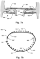
- the first and second anterior portions 114, 114' may each have a straighter extension or at least an extension which is less bent than the bow-shaped posterior sides 113, 113'. This is exemplified in Fig. 7b .
- the first and second anterior portions 114, 114' may thus be adapted to conform to an anterior aspect of the heart valve, i.e.
- the first support ring 101 may be adapted to be arranged on an atrial side of the heart valve
- the second support ring 102 may be adapted to be arranged on a ventricular side of the heart valve, as exemplified in Fig. 7a.
- Fig. 7b show schematic top-down view where the second ring 102 is shown with dashed lines and the first ring 101 is shown with a solid line.
- the transition point between the first and second rings 101, 102 is in the example of Fig. 7b at the commissure denoted 302'.
- the first anterior portion 114 may comprises an anterior stent 105c.
- the anterior stent 105c comprises a plurality of retention units 104 extending towards the second support ring 102 in their expanded state (p 2 ), as schematically illustrated in Fig. 1 .
- the second anterior portion 114' may comprise a smooth surface free from retention units 104, as further shown in the example of Fig. 1 . This provides for a secure anchoring into the tissue with the first anterior portion 114 at the atrial side, while at the same time the risk of tissue damage is minimized in the ventricle along the second anterior portion 114'.
- the first posterior bow 113 may comprise a first posterior stent 105a.
- the first posterior stent 105a may comprise a first plurality of retention units 104 extending towards the second support ring 102 in their expanded state (p 2 ), as schematically illustrated in Fig. 1 .
- the second posterior bow 113' may comprise a second posterior stent 105b.
- the second posterior stent 105b may comprise a second plurality of retention units 104' extending in a direction towards the first plurality of retention units 104.
- the first and second pluralities of retention units 104, 104' may thus extend in opposite directions along the axial direction 103.
- Having a plurality of separate stents 105a, 105b, 105c, arranged along the posterior bows 113, 113', and the first anterior portion 114 allows further for having the stents 105a, 105b, 105c, displaced from intermediate portions 109 extending therebetween.
- the intermediate portions 109 as indicated in Fig. 1 have a greater radius of curvature than the posterior bows 113, 113', and the anterior portions 114, 114'.
- Having stents 105a, 105b, 105c, arranged at a distance from the intermediate portions 109 provides for maintaining a greater flexibility of the first and second support rings 101, 102, along the intermediate portions 109, and a facilitated bending along the latter.
- the first support ring 101 may transition to the second support ring 102 over a transition section 120, as illustrated in Fig. 6 .
- the stent 105 has been omitted from Fig. 6 for a clearer illustration.
- the transition section 120 is adapted to be arranged at a commissure 302, 302', of the heart valve leaflets, e.g. at a commissure 302' as illustrated in Fig. 7b .
- the first and second support rings 101, 102 extend in respective first and second coil planes 101', 102', being essentially perpendicular to the central axis 103.
- the transition section 120 may bend at least partly along a radial direction (r) of the coiled configuration of the first and second support rings 101, 102, where the radial direction (r) is perpendicular to the central axis 103, so that the transition section 120 is concave towards the radial direction (r).
- Such concave bend, or "C-curve" of the transition section 120 towards the radial direction (R) provides for further improving the coaptation of the first and second support rings 101, 102, to the valve anatomy close to the commissure 302, 302'.
- the risk of having a disadvantageous force transfer or friction between the moving valve leaflets and any of the support rings 101, 102, at the commissure 302, 302', is minimized.
- the first and second support rings 101, 102 may extend along the annulus as far as possible while extending through the commissure 302, 302', with minimized impact on the valve motion, as the concave bend of the transition section 120 allows for adapting to anatomies where the commissure 302, 302', is located loser to the central axis 103 than the annulus.
- the annuloplasty device 100 may thus be secured at the valve in a further improved manner, while the risk of dislocations in the long term is minimized.
- the peripheral off-set distance between the two free ends 116, 116' thus extends substantially perpendicular to the central axis 103. This means that, when the device 100 is positioned in the implanted state, around the annulus of the heart valve, the two free ends 116, 116', will be separated along the plane of the valve. Having such off-set 117 in the plane of the valve, resulting in a reduced length of the first or second support rings 101, 102, may be advantageous in some anatomies where there might be a risk of interference of the first or second support rings 101, 102, with the valve motion.
- the method 200 allows for a facilitated anchoring of the annuloplasty device 100 at the heart valve, due to the robust and reliable fixation mechanism provided by stents 105, 105a, 10b, 105c, and the retention units 104, 104', fixed thereto.
- a further method 200 is schematically illustrated in Fig. 11b .
- the method 200 may comprise positioning 2031 an anterior stent 105c on the atrial side along a first anterior portion 114 of the first support ring 101, and positioning 2032 a first posterior stent 105a on the atrial side along a first posterior bow 113 of the first support ring 101.
- the method 200 may further comprise positioning 2033 a second posterior stent 105b on the ventricular side along a second posterior bow 113' of the second support ring 102.
- the method 200 may further comprise engaging 2041 retention units 104 of the anterior stent 105c into valve tissue on the atrial side, and engaging 2042 retention units 104, 104', of the first and second posterior stents 105a, 105b, into valve tissue on the respective atrial and ventricular side to anchor the annuloplasty device 100 at the heart valve.
- a secure fixation of the annuloplasty device at the opposite sides of the heart valve leaflets is thus provided, as described further above with respect to Figs. 1 - 10 .
- the method 200 may comprise positioning the first and second support rings 101, 102, on the respective atrial and ventricular sides of the heart valve by ejecting 2021 the first and second support rings from a delivery catheter (not shown), where the retention units 104, 104', move from a retracted state (p 1 ) to an expanded state (p 2 ) as the first and second support rings 101, 102, are ejected from the delivery catheter.
- the retention units 104, 104' may be aligned essentially flush with an outer diameter (D) of the stent 105, 105a, 105b, 105c, in the retracted state (p 1 ) when the first and second support rings 101, 102, moves along a lumen if the delivery catheter.
Landscapes
- Health & Medical Sciences (AREA)
- Cardiology (AREA)
- Life Sciences & Earth Sciences (AREA)
- Engineering & Computer Science (AREA)
- General Health & Medical Sciences (AREA)
- Biomedical Technology (AREA)
- Heart & Thoracic Surgery (AREA)
- Veterinary Medicine (AREA)
- Public Health (AREA)
- Animal Behavior & Ethology (AREA)
- Vascular Medicine (AREA)
- Oral & Maxillofacial Surgery (AREA)
- Transplantation (AREA)
- Surgery (AREA)
- Nuclear Medicine, Radiotherapy & Molecular Imaging (AREA)
- Medical Informatics (AREA)
- Molecular Biology (AREA)
- Prostheses (AREA)
Claims (15)
- Dispositif d'annuloplastie (100) comprenant des premier (101) et second (102) anneaux de support ayant une configuration en spirale dans laquelle les premier et second anneaux de support sont disposés en spirale autour d'un axe central (103),les premier et second anneaux de support étant configurés pour être disposés sur des côtés opposés de feuillets de valve cardiaque natifs (301) d'une valve cardiaque, caractérisé parune endoprothèse (105, 105a, 105b, 105c) agencée autour d'au moins une partie du premier et/ou du second anneau de support,l'endoprothèse comprenant des unités de retenue (104, 104'), etl'endoprothèse étant radialement contractable le long d'une direction radiale (R), perpendiculaire à une direction longitudinale (L) de l'endoprothèse, de sorte que l'endoprothèse exerce une force (F) sur le premier et/ou le second anneau de support.
- Dispositif d'annuloplastie selon la revendication 1, les unités de retenue étant formées à partir du matériau de l'endoprothèse, les unités de retenue étant ainsi intégrées à l'endoprothèse.
- Dispositif d'annuloplastie selon la revendication 1 ou 2, les unités de retenue comprenant un matériau à mémoire de forme, l'activation du matériau à mémoire de forme faisant passer les unités de retenue d'un état rétracté (p1) à un état expansé (p2).
- Dispositif d'annuloplastie selon l'une quelconque des revendications 1 à 3, les unités de retenue pouvant être déplacées de manière élastique d'un état rétracté (p1) à un état expansé (p2).
- Dispositif d'annuloplastie selon la revendication 4, les unités de retenue étant flexibles pour se plier de l'état expansé (p2) à l'état rétracté (p1) .
- Dispositif d'annuloplastie selon la revendication 5, les unités de retenue étant alignées essentiellement au même niveau qu'un diamètre externe (D) de l'endoprothèse à l'état rétracté.
- Dispositif d'annuloplastie selon l'une quelconque des revendications 1 à 6, l'endoprothèse comprenant une pluralité d'éléments de support (108) formant une armature d'endoprothèse en cellules fermées (122), un premier élément de support (108a) de la pluralité d'éléments de support d'une cellule (122) étant mobile en tant qu'unité de retenue (104, 104') le long d'une direction radiale (R), perpendiculaire à une direction longitudinale (L) de l'endoprothèse.
- Dispositif d'annuloplastie selon la revendication 8, l'endoprothèse comprenant un matériau à mémoire de forme, l'activation du matériau à mémoire de forme amenant l'endoprothèse à se contracter jusqu'à un diamètre réduit, le long d'une direction radiale (R), pour appliquer ladite force sur le premier et/ou le second anneau de support.
- Dispositif d'annuloplastie selon l'une quelconque des revendications 1 à 8, l'endoprothèse comprenant des éléments de support (108) configurés pour être contractables et expansibles de sorte qu'un diamètre extérieur (D1, D2) de l'endoprothèse est variable entre un diamètre expansé (D1) et un diamètre contracté (D2) tandis qu'une longueur prédéfinie (L1) de l'endoprothèse est essentiellement maintenue.
- Dispositif d'annuloplastie selon la revendication 9, les éléments de support comprenant un cadre principal allongé (121) s'étendant essentiellement le long de la direction longitudinale (L) de l'endoprothèse, le cadre principal allongé définissant la longueur prédéfinie (L1) de l'endoprothèse, le cadre principal allongé ayant ainsi une position essentiellement fixe dans la direction longitudinale (L) lorsque le diamètre extérieur de l'endoprothèse varie entre le diamètre expansé (D1) et le diamètre contracté (D2).
- Dispositif d'annuloplastie selon l'une quelconque des revendications 1 à 10, comprenant un couvercle (106) agencé autour d'au moins une partie du premier et/ou du second anneau de support, et l'endoprothèse étant agencée autour d'au moins une partie du couvercle.
- Dispositif d'annuloplastie selon la revendication 11, l'endoprothèse exerçant une force sur le couvercle de sorte que le couvercle est pincé entre l'endoprothèse et le premier et/ou le second anneau de support.
- Dispositif d'annuloplastie selon l'une quelconque des revendications 1 à 12, le premier anneau de support comprenant un premier arc postérieur (113) et une première partie antérieure (114), le second anneau de support comprenant un second arc postérieur (113') et une seconde partie antérieure (114'),les premier et second arcs postérieurs étant adaptés pour épouser la forme d'une apparence postérieure de ladite valve cardiaque, et les première et seconde parties antérieures étant adaptées pour épouser la forme d'une apparence antérieure de ladite valve cardiaque,la première partie antérieure (114) comprenant une endoprothèse antérieure (105c), l'endoprothèse antérieure comprenant une pluralité d'unités de retenue, etla seconde partie antérieure (114') comprenant une surface lisse dépourvue d'unités de retenue.
- Dispositif d'annuloplastie selon la revendication 13, le premier arc postérieur (113) comprenant une première endoprothèse postérieure (105a) comprenant une première pluralité d'unités de retenue, et
le second arc postérieur (113') comprenant une seconde endoprothèse postérieure (105b) comprenant une seconde pluralité d'unités de retenue s'étendant dans une direction vers la première pluralité d'unités de retenue. - Dispositif d'annuloplastie selon l'une quelconque des revendications 1 à 14, le premier anneau de support passant vers le second anneau de support sur une section de transition (120), la section de transition étant adaptée pour être agencée au niveau d'une commissure (302, 302') des feuillets de valve cardiaque, les premier et second anneaux de support s'étendant dans un premier et un second plan de bobine (101', 102') qui sont essentiellement perpendiculaires à l'axe central,
la section de transition se pliant au moins partiellement le long de l'axe central de sorte que le premier plan de bobine est séparé d'une distance (d1) du second plan de bobine le long de l'axe central au niveau de la région de transition.
Priority Applications (13)
| Application Number | Priority Date | Filing Date | Title |
|---|---|---|---|
| ES20207665T ES3047869T3 (en) | 2020-11-13 | 2020-11-13 | Annuloplasty device |
| EP20207665.9A EP4000559B1 (fr) | 2020-11-13 | 2020-11-13 | Dispositif d'annuloplastie |
| CA3185826A CA3185826A1 (fr) | 2020-07-13 | 2021-01-13 | Dispositif d'annuloplastie |
| PCT/EP2021/050600 WO2022012782A1 (fr) | 2020-07-13 | 2021-01-13 | Dispositif d'annuloplastie |
| EP24195509.5A EP4450028A3 (fr) | 2020-07-13 | 2021-01-13 | Dispositif d'annuloplastie |
| CN202180062295.3A CN116096326A (zh) | 2020-07-13 | 2021-01-13 | 瓣环成形术装置 |
| EP21700432.4A EP4178487B1 (fr) | 2020-07-13 | 2021-01-13 | Dispositif d'annuloplastie |
| US18/015,731 US20230255771A1 (en) | 2020-07-13 | 2021-01-13 | Annuloplasty device |
| JP2023528621A JP7660674B2 (ja) | 2020-11-13 | 2021-10-31 | 弁輪形成装置 |
| US18/036,800 US20240016606A1 (en) | 2020-11-13 | 2021-10-31 | Annuloplasty Device |
| PCT/EP2021/080228 WO2022101041A1 (fr) | 2020-11-13 | 2021-10-31 | Dispositif d'annuloplastie |
| CN202180078509.6A CN116472010A (zh) | 2020-11-13 | 2021-10-31 | 瓣环成形术装置 |
| CA3196820A CA3196820A1 (fr) | 2020-11-13 | 2021-10-31 | Dispositif d'annuloplastie |
Applications Claiming Priority (1)
| Application Number | Priority Date | Filing Date | Title |
|---|---|---|---|
| EP20207665.9A EP4000559B1 (fr) | 2020-11-13 | 2020-11-13 | Dispositif d'annuloplastie |
Publications (2)
| Publication Number | Publication Date |
|---|---|
| EP4000559A1 EP4000559A1 (fr) | 2022-05-25 |
| EP4000559B1 true EP4000559B1 (fr) | 2025-07-02 |
Family
ID=73451996
Family Applications (3)
| Application Number | Title | Priority Date | Filing Date |
|---|---|---|---|
| EP20207665.9A Active EP4000559B1 (fr) | 2020-07-13 | 2020-11-13 | Dispositif d'annuloplastie |
| EP24195509.5A Pending EP4450028A3 (fr) | 2020-07-13 | 2021-01-13 | Dispositif d'annuloplastie |
| EP21700432.4A Active EP4178487B1 (fr) | 2020-07-13 | 2021-01-13 | Dispositif d'annuloplastie |
Family Applications After (2)
| Application Number | Title | Priority Date | Filing Date |
|---|---|---|---|
| EP24195509.5A Pending EP4450028A3 (fr) | 2020-07-13 | 2021-01-13 | Dispositif d'annuloplastie |
| EP21700432.4A Active EP4178487B1 (fr) | 2020-07-13 | 2021-01-13 | Dispositif d'annuloplastie |
Country Status (7)
| Country | Link |
|---|---|
| US (2) | US20230255771A1 (fr) |
| EP (3) | EP4000559B1 (fr) |
| JP (1) | JP7660674B2 (fr) |
| CN (2) | CN116096326A (fr) |
| CA (2) | CA3185826A1 (fr) |
| ES (1) | ES3047869T3 (fr) |
| WO (2) | WO2022012782A1 (fr) |
Families Citing this family (5)
| Publication number | Priority date | Publication date | Assignee | Title |
|---|---|---|---|---|
| US11234818B2 (en) * | 2018-05-21 | 2022-02-01 | Medtentia International Ltd Oy | Annuloplasty device |
| US20250302623A1 (en) * | 2022-05-11 | 2025-10-02 | Hvr Cardio Oy | Annuloplasty device |
| EP4400077B1 (fr) * | 2023-01-15 | 2025-11-05 | HVR Cardio Oy | Dispositif d'annuloplastie |
| WO2025019174A1 (fr) * | 2023-07-19 | 2025-01-23 | Edwards Lifesciences Corporation | Dispositif d'accueil de prothèse valvulaire |
| EP4497414A1 (fr) * | 2023-07-23 | 2025-01-29 | HVR Cardio Oy | Dispositif d'annuloplastie |
Family Cites Families (22)
| Publication number | Priority date | Publication date | Assignee | Title |
|---|---|---|---|---|
| US6419696B1 (en) * | 2000-07-06 | 2002-07-16 | Paul A. Spence | Annuloplasty devices and related heart valve repair methods |
| US7935145B2 (en) * | 2001-05-17 | 2011-05-03 | Edwards Lifesciences Corporation | Annuloplasty ring for ischemic mitral valve insuffuciency |
| US7311730B2 (en) * | 2004-02-13 | 2007-12-25 | Shlomo Gabbay | Support apparatus and heart valve prosthesis for sutureless implantation |
| SE530568C2 (sv) * | 2006-11-13 | 2008-07-08 | Medtentia Ab | Anordning och metod för förbättring av funktionen hos en hjärtklaff |
| CN102438552A (zh) * | 2009-03-19 | 2012-05-02 | 米利佩德有限责任公司 | 重构心脏特征 |
| US8932350B2 (en) * | 2010-11-30 | 2015-01-13 | Edwards Lifesciences Corporation | Reduced dehiscence annuloplasty ring |
| US8858623B2 (en) * | 2011-11-04 | 2014-10-14 | Valtech Cardio, Ltd. | Implant having multiple rotational assemblies |
| CN108283534B (zh) * | 2012-01-31 | 2019-09-24 | 米特拉尔维尔福科技有限责任公司 | 二尖瓣停放装置和系统 |
| US9180008B2 (en) * | 2012-02-29 | 2015-11-10 | Valcare, Inc. | Methods, devices, and systems for percutaneously anchoring annuloplasty rings |
| JP2018094430A (ja) * | 2013-03-15 | 2018-06-21 | シメティス・ソシエテ・アノニムSymetis Sa | 経カテーテルステント弁に関する改良 |
| WO2014179761A1 (fr) * | 2013-05-03 | 2014-11-06 | Medtronic Inc. | Dispositifs médicaux destinés à être implantés dans une valve et procédés associés |
| ES2960716T3 (es) | 2013-08-12 | 2024-03-06 | Mitral Valve Tech Sarl | Aparato para implantar una válvula cardíaca de sustitución |
| US10321992B2 (en) * | 2016-02-01 | 2019-06-18 | Medtronic, Inc. | Heart valve prostheses having multiple support arms and methods for percutaneous heart valve replacement |
| US10561423B2 (en) * | 2016-07-25 | 2020-02-18 | Virender K. Sharma | Cardiac shunt device and delivery system |
| US10722359B2 (en) * | 2016-08-26 | 2020-07-28 | Edwards Lifesciences Corporation | Heart valve docking devices and systems |
| CR20190069A (es) * | 2016-08-26 | 2019-05-14 | Edwards Lifesciences Corp | Valvulas y sistemas de acoplamiento de valvulas corazon |
| EP3395296B1 (fr) * | 2017-04-28 | 2019-12-18 | Medtentia International Ltd Oy | Implant d'annuloplastie |
| EP3476366B1 (fr) * | 2017-10-27 | 2020-12-16 | Medtentia International Ltd Oy | Implant d'annuloplastie |
| US10980635B2 (en) * | 2018-01-07 | 2021-04-20 | William Joseph Drasler | Annuloplasty device and methods |
| EP3737336B1 (fr) * | 2018-01-08 | 2022-09-28 | Medtentia International Ltd Oy | Dispositif d'annuloplastie |
| WO2019223975A1 (fr) * | 2018-05-21 | 2019-11-28 | Medtentia International Ltd Oy | Dispositif d'annuloplastie |
| US11234818B2 (en) * | 2018-05-21 | 2022-02-01 | Medtentia International Ltd Oy | Annuloplasty device |
-
2020
- 2020-11-13 EP EP20207665.9A patent/EP4000559B1/fr active Active
- 2020-11-13 ES ES20207665T patent/ES3047869T3/es active Active
-
2021
- 2021-01-13 US US18/015,731 patent/US20230255771A1/en active Pending
- 2021-01-13 CA CA3185826A patent/CA3185826A1/fr active Pending
- 2021-01-13 WO PCT/EP2021/050600 patent/WO2022012782A1/fr not_active Ceased
- 2021-01-13 EP EP24195509.5A patent/EP4450028A3/fr active Pending
- 2021-01-13 EP EP21700432.4A patent/EP4178487B1/fr active Active
- 2021-01-13 CN CN202180062295.3A patent/CN116096326A/zh active Pending
- 2021-10-31 JP JP2023528621A patent/JP7660674B2/ja active Active
- 2021-10-31 WO PCT/EP2021/080228 patent/WO2022101041A1/fr not_active Ceased
- 2021-10-31 CN CN202180078509.6A patent/CN116472010A/zh active Pending
- 2021-10-31 US US18/036,800 patent/US20240016606A1/en active Pending
- 2021-10-31 CA CA3196820A patent/CA3196820A1/fr active Pending
Also Published As
| Publication number | Publication date |
|---|---|
| JP2024501398A (ja) | 2024-01-12 |
| EP4178487B1 (fr) | 2024-08-21 |
| EP4450028A2 (fr) | 2024-10-23 |
| CN116096326A (zh) | 2023-05-09 |
| CN116472010A (zh) | 2023-07-21 |
| EP4000559A1 (fr) | 2022-05-25 |
| CA3196820A1 (fr) | 2022-05-19 |
| WO2022012782A1 (fr) | 2022-01-20 |
| EP4178487A1 (fr) | 2023-05-17 |
| ES3047869T3 (en) | 2025-12-05 |
| US20240016606A1 (en) | 2024-01-18 |
| EP4450028A3 (fr) | 2025-01-29 |
| JP7660674B2 (ja) | 2025-04-11 |
| CA3185826A1 (fr) | 2022-01-20 |
| WO2022101041A1 (fr) | 2022-05-19 |
| US20230255771A1 (en) | 2023-08-17 |
Similar Documents
| Publication | Publication Date | Title |
|---|---|---|
| EP3700467B1 (fr) | Implant d'annuloplastie | |
| EP4000559A1 (fr) | Dispositif d'annuloplastie | |
| US12357461B2 (en) | Annuloplasty device | |
| EP3998991B1 (fr) | Dispositif d'annuloplastie | |
| EP4522076B1 (fr) | Dispositif d'annuloplastie | |
| EP4465924B1 (fr) | Dispositif d'annuloplastie | |
| EP4178489B1 (fr) | Dispositif d'annuloplastie | |
| EP4400077B1 (fr) | Dispositif d'annuloplastie | |
| WO2024110578A1 (fr) | Dispositif de fixation à des fins d'implantation |
Legal Events
| Date | Code | Title | Description |
|---|---|---|---|
| PUAI | Public reference made under article 153(3) epc to a published international application that has entered the european phase |
Free format text: ORIGINAL CODE: 0009012 |
|
| STAA | Information on the status of an ep patent application or granted ep patent |
Free format text: STATUS: THE APPLICATION HAS BEEN PUBLISHED |
|
| AK | Designated contracting states |
Kind code of ref document: A1 Designated state(s): AL AT BE BG CH CY CZ DE DK EE ES FI FR GB GR HR HU IE IS IT LI LT LU LV MC MK MT NL NO PL PT RO RS SE SI SK SM TR |
|
| STAA | Information on the status of an ep patent application or granted ep patent |
Free format text: STATUS: REQUEST FOR EXAMINATION WAS MADE |
|
| 17P | Request for examination filed |
Effective date: 20221125 |
|
| RBV | Designated contracting states (corrected) |
Designated state(s): AL AT BE BG CH CY CZ DE DK EE ES FI FR GB GR HR HU IE IS IT LI LT LU LV MC MK MT NL NO PL PT RO RS SE SI SK SM TR |
|
| RAP3 | Party data changed (applicant data changed or rights of an application transferred) |
Owner name: HVR CARDIO OY |
|
| STAA | Information on the status of an ep patent application or granted ep patent |
Free format text: STATUS: EXAMINATION IS IN PROGRESS |
|
| 17Q | First examination report despatched |
Effective date: 20240715 |
|
| GRAP | Despatch of communication of intention to grant a patent |
Free format text: ORIGINAL CODE: EPIDOSNIGR1 |
|
| STAA | Information on the status of an ep patent application or granted ep patent |
Free format text: STATUS: GRANT OF PATENT IS INTENDED |
|
| INTG | Intention to grant announced |
Effective date: 20250128 |
|
| RIN1 | Information on inventor provided before grant (corrected) |
Inventor name: KERAENEN, OLLI |
|
| GRAS | Grant fee paid |
Free format text: ORIGINAL CODE: EPIDOSNIGR3 |
|
| GRAA | (expected) grant |
Free format text: ORIGINAL CODE: 0009210 |
|
| STAA | Information on the status of an ep patent application or granted ep patent |
Free format text: STATUS: THE PATENT HAS BEEN GRANTED |
|
| AK | Designated contracting states |
Kind code of ref document: B1 Designated state(s): AL AT BE BG CH CY CZ DE DK EE ES FI FR GB GR HR HU IE IS IT LI LT LU LV MC MK MT NL NO PL PT RO RS SE SI SK SM TR |
|
| REG | Reference to a national code |
Ref country code: GB Ref legal event code: FG4D |
|
| REG | Reference to a national code |
Ref country code: CH Ref legal event code: EP |
|
| REG | Reference to a national code |
Ref country code: DE Ref legal event code: R096 Ref document number: 602020053706 Country of ref document: DE |
|
| REG | Reference to a national code |
Ref country code: IE Ref legal event code: FG4D |
|
| P01 | Opt-out of the competence of the unified patent court (upc) registered |
Free format text: CASE NUMBER: APP_31794/2025 Effective date: 20250701 |
|
| REG | Reference to a national code |
Ref country code: NL Ref legal event code: MP Effective date: 20250702 |
|
| REG | Reference to a national code |
Ref country code: ES Ref legal event code: FG2A Ref document number: 3047869 Country of ref document: ES Kind code of ref document: T3 Effective date: 20251205 |
|
| PG25 | Lapsed in a contracting state [announced via postgrant information from national office to epo] |
Ref country code: PT Free format text: LAPSE BECAUSE OF FAILURE TO SUBMIT A TRANSLATION OF THE DESCRIPTION OR TO PAY THE FEE WITHIN THE PRESCRIBED TIME-LIMIT Effective date: 20251103 |
|
| PG25 | Lapsed in a contracting state [announced via postgrant information from national office to epo] |
Ref country code: NL Free format text: LAPSE BECAUSE OF FAILURE TO SUBMIT A TRANSLATION OF THE DESCRIPTION OR TO PAY THE FEE WITHIN THE PRESCRIBED TIME-LIMIT Effective date: 20250702 |
|
| REG | Reference to a national code |
Ref country code: AT Ref legal event code: MK05 Ref document number: 1808401 Country of ref document: AT Kind code of ref document: T Effective date: 20250702 |
|
| PG25 | Lapsed in a contracting state [announced via postgrant information from national office to epo] |
Ref country code: IS Free format text: LAPSE BECAUSE OF FAILURE TO SUBMIT A TRANSLATION OF THE DESCRIPTION OR TO PAY THE FEE WITHIN THE PRESCRIBED TIME-LIMIT Effective date: 20251102 |
|
| PGFP | Annual fee paid to national office [announced via postgrant information from national office to epo] |
Ref country code: DE Payment date: 20251126 Year of fee payment: 6 |
|
| PGFP | Annual fee paid to national office [announced via postgrant information from national office to epo] |
Ref country code: GB Payment date: 20251127 Year of fee payment: 6 |
|
| PG25 | Lapsed in a contracting state [announced via postgrant information from national office to epo] |
Ref country code: NO Free format text: LAPSE BECAUSE OF FAILURE TO SUBMIT A TRANSLATION OF THE DESCRIPTION OR TO PAY THE FEE WITHIN THE PRESCRIBED TIME-LIMIT Effective date: 20251002 |
|
| REG | Reference to a national code |
Ref country code: LT Ref legal event code: MG9D |
|
| PG25 | Lapsed in a contracting state [announced via postgrant information from national office to epo] |
Ref country code: AT Free format text: LAPSE BECAUSE OF FAILURE TO SUBMIT A TRANSLATION OF THE DESCRIPTION OR TO PAY THE FEE WITHIN THE PRESCRIBED TIME-LIMIT Effective date: 20250702 |
|
| PG25 | Lapsed in a contracting state [announced via postgrant information from national office to epo] |
Ref country code: FI Free format text: LAPSE BECAUSE OF FAILURE TO SUBMIT A TRANSLATION OF THE DESCRIPTION OR TO PAY THE FEE WITHIN THE PRESCRIBED TIME-LIMIT Effective date: 20250702 |
|
| PGFP | Annual fee paid to national office [announced via postgrant information from national office to epo] |
Ref country code: IT Payment date: 20251128 Year of fee payment: 6 |
|
| PG25 | Lapsed in a contracting state [announced via postgrant information from national office to epo] |
Ref country code: HR Free format text: LAPSE BECAUSE OF FAILURE TO SUBMIT A TRANSLATION OF THE DESCRIPTION OR TO PAY THE FEE WITHIN THE PRESCRIBED TIME-LIMIT Effective date: 20250702 |
|
| PGFP | Annual fee paid to national office [announced via postgrant information from national office to epo] |
Ref country code: FR Payment date: 20251126 Year of fee payment: 6 |
|
| PG25 | Lapsed in a contracting state [announced via postgrant information from national office to epo] |
Ref country code: GR Free format text: LAPSE BECAUSE OF FAILURE TO SUBMIT A TRANSLATION OF THE DESCRIPTION OR TO PAY THE FEE WITHIN THE PRESCRIBED TIME-LIMIT Effective date: 20251003 |
|
| PG25 | Lapsed in a contracting state [announced via postgrant information from national office to epo] |
Ref country code: SE Free format text: LAPSE BECAUSE OF FAILURE TO SUBMIT A TRANSLATION OF THE DESCRIPTION OR TO PAY THE FEE WITHIN THE PRESCRIBED TIME-LIMIT Effective date: 20250702 Ref country code: CZ Free format text: LAPSE BECAUSE OF FAILURE TO SUBMIT A TRANSLATION OF THE DESCRIPTION OR TO PAY THE FEE WITHIN THE PRESCRIBED TIME-LIMIT Effective date: 20250702 |
|
| PG25 | Lapsed in a contracting state [announced via postgrant information from national office to epo] |
Ref country code: LV Free format text: LAPSE BECAUSE OF FAILURE TO SUBMIT A TRANSLATION OF THE DESCRIPTION OR TO PAY THE FEE WITHIN THE PRESCRIBED TIME-LIMIT Effective date: 20250702 |
|
| PG25 | Lapsed in a contracting state [announced via postgrant information from national office to epo] |
Ref country code: BG Free format text: LAPSE BECAUSE OF FAILURE TO SUBMIT A TRANSLATION OF THE DESCRIPTION OR TO PAY THE FEE WITHIN THE PRESCRIBED TIME-LIMIT Effective date: 20250702 Ref country code: PL Free format text: LAPSE BECAUSE OF FAILURE TO SUBMIT A TRANSLATION OF THE DESCRIPTION OR TO PAY THE FEE WITHIN THE PRESCRIBED TIME-LIMIT Effective date: 20250702 |
|
| PG25 | Lapsed in a contracting state [announced via postgrant information from national office to epo] |
Ref country code: RS Free format text: LAPSE BECAUSE OF FAILURE TO SUBMIT A TRANSLATION OF THE DESCRIPTION OR TO PAY THE FEE WITHIN THE PRESCRIBED TIME-LIMIT Effective date: 20251002 |
|
| PGFP | Annual fee paid to national office [announced via postgrant information from national office to epo] |
Ref country code: ES Payment date: 20251209 Year of fee payment: 6 |
|
| PG25 | Lapsed in a contracting state [announced via postgrant information from national office to epo] |
Ref country code: RO Free format text: LAPSE BECAUSE OF FAILURE TO SUBMIT A TRANSLATION OF THE DESCRIPTION OR TO PAY THE FEE WITHIN THE PRESCRIBED TIME-LIMIT Effective date: 20250702 |
|
| PG25 | Lapsed in a contracting state [announced via postgrant information from national office to epo] |
Ref country code: SM Free format text: LAPSE BECAUSE OF FAILURE TO SUBMIT A TRANSLATION OF THE DESCRIPTION OR TO PAY THE FEE WITHIN THE PRESCRIBED TIME-LIMIT Effective date: 20250702 |
|
| PG25 | Lapsed in a contracting state [announced via postgrant information from national office to epo] |
Ref country code: DK Free format text: LAPSE BECAUSE OF FAILURE TO SUBMIT A TRANSLATION OF THE DESCRIPTION OR TO PAY THE FEE WITHIN THE PRESCRIBED TIME-LIMIT Effective date: 20250702 |
|
| PG25 | Lapsed in a contracting state [announced via postgrant information from national office to epo] |
Ref country code: SK Free format text: LAPSE BECAUSE OF FAILURE TO SUBMIT A TRANSLATION OF THE DESCRIPTION OR TO PAY THE FEE WITHIN THE PRESCRIBED TIME-LIMIT Effective date: 20250702 Ref country code: EE Free format text: LAPSE BECAUSE OF FAILURE TO SUBMIT A TRANSLATION OF THE DESCRIPTION OR TO PAY THE FEE WITHIN THE PRESCRIBED TIME-LIMIT Effective date: 20250702 |
|
| PLBE | No opposition filed within time limit |
Free format text: ORIGINAL CODE: 0009261 |
|
| STAA | Information on the status of an ep patent application or granted ep patent |
Free format text: STATUS: NO OPPOSITION FILED WITHIN TIME LIMIT |