EP4000581B1 - Support d'un élément d'entrainement fascial, élément d'entrainement fascial, et dispositif de maintien et système d'entrainement - Google Patents
Support d'un élément d'entrainement fascial, élément d'entrainement fascial, et dispositif de maintien et système d'entrainement Download PDFInfo
- Publication number
- EP4000581B1 EP4000581B1 EP21183716.6A EP21183716A EP4000581B1 EP 4000581 B1 EP4000581 B1 EP 4000581B1 EP 21183716 A EP21183716 A EP 21183716A EP 4000581 B1 EP4000581 B1 EP 4000581B1
- Authority
- EP
- European Patent Office
- Prior art keywords
- fascia
- holder
- training element
- holding
- training
- Prior art date
- Legal status (The legal status is an assumption and is not a legal conclusion. Google has not performed a legal analysis and makes no representation as to the accuracy of the status listed.)
- Active
Links
Images


Classifications
-
- A—HUMAN NECESSITIES
- A61—MEDICAL OR VETERINARY SCIENCE; HYGIENE
- A61H—PHYSICAL THERAPY APPARATUS, e.g. DEVICES FOR LOCATING OR STIMULATING REFLEX POINTS IN THE BODY; ARTIFICIAL RESPIRATION; MASSAGE; BATHING DEVICES FOR SPECIAL THERAPEUTIC OR HYGIENIC PURPOSES OR SPECIFIC PARTS OF THE BODY
- A61H15/00—Massage by means of rollers, balls, e.g. inflatable, chains, or roller chains
-
- A—HUMAN NECESSITIES
- A61—MEDICAL OR VETERINARY SCIENCE; HYGIENE
- A61H—PHYSICAL THERAPY APPARATUS, e.g. DEVICES FOR LOCATING OR STIMULATING REFLEX POINTS IN THE BODY; ARTIFICIAL RESPIRATION; MASSAGE; BATHING DEVICES FOR SPECIAL THERAPEUTIC OR HYGIENIC PURPOSES OR SPECIFIC PARTS OF THE BODY
- A61H15/00—Massage by means of rollers, balls, e.g. inflatable, chains, or roller chains
- A61H2015/0007—Massage by means of rollers, balls, e.g. inflatable, chains, or roller chains with balls or rollers rotating about their own axis
-
- A—HUMAN NECESSITIES
- A61—MEDICAL OR VETERINARY SCIENCE; HYGIENE
- A61H—PHYSICAL THERAPY APPARATUS, e.g. DEVICES FOR LOCATING OR STIMULATING REFLEX POINTS IN THE BODY; ARTIFICIAL RESPIRATION; MASSAGE; BATHING DEVICES FOR SPECIAL THERAPEUTIC OR HYGIENIC PURPOSES OR SPECIFIC PARTS OF THE BODY
- A61H15/00—Massage by means of rollers, balls, e.g. inflatable, chains, or roller chains
- A61H2015/0007—Massage by means of rollers, balls, e.g. inflatable, chains, or roller chains with balls or rollers rotating about their own axis
- A61H2015/0014—Massage by means of rollers, balls, e.g. inflatable, chains, or roller chains with balls or rollers rotating about their own axis cylinder-like, i.e. rollers
-
- A—HUMAN NECESSITIES
- A61—MEDICAL OR VETERINARY SCIENCE; HYGIENE
- A61H—PHYSICAL THERAPY APPARATUS, e.g. DEVICES FOR LOCATING OR STIMULATING REFLEX POINTS IN THE BODY; ARTIFICIAL RESPIRATION; MASSAGE; BATHING DEVICES FOR SPECIAL THERAPEUTIC OR HYGIENIC PURPOSES OR SPECIFIC PARTS OF THE BODY
- A61H15/00—Massage by means of rollers, balls, e.g. inflatable, chains, or roller chains
- A61H2015/0007—Massage by means of rollers, balls, e.g. inflatable, chains, or roller chains with balls or rollers rotating about their own axis
- A61H2015/0042—Balls or spheres
-
- A—HUMAN NECESSITIES
- A61—MEDICAL OR VETERINARY SCIENCE; HYGIENE
- A61H—PHYSICAL THERAPY APPARATUS, e.g. DEVICES FOR LOCATING OR STIMULATING REFLEX POINTS IN THE BODY; ARTIFICIAL RESPIRATION; MASSAGE; BATHING DEVICES FOR SPECIAL THERAPEUTIC OR HYGIENIC PURPOSES OR SPECIFIC PARTS OF THE BODY
- A61H15/00—Massage by means of rollers, balls, e.g. inflatable, chains, or roller chains
- A61H2015/0064—Massage by means of rollers, balls, e.g. inflatable, chains, or roller chains with freely rotating spheres
Definitions
- the invention relates to a training system for massaging the fascia in various muscle parts of a body.
- Fascia training elements for massaging certain muscle groups of the human body are well known.
- the fascia training element is usually placed on the floor and the user positions the muscle group to be massaged, for example a thigh or the back, on the fascia training element and moves the muscle group back and forth relative to the fascia training element.
- the fascia training elements are not fixed in place, so that they constantly change their position on the floor during use and the user must always adjust their starting position or the starting position of the muscle group to be massaged to the unintentionally changing position of the fascia training element.
- fascia training elements are mainly roll-like bodies such as cylinders or dumbbells etc. or balls.
- Such holders are not yet known for spherical fascia training elements. It is only known to fix fascia balls/spheres so that they can rotate along an axis, although this type of holder means that any flexibility in the use of the fascia ball is lost. For example, see the publication DE 20 2016 006 426 U1 referred to.
- holding devices for fascia rolls are known with which the roll or its holder can be fixed in a fixed and rotatable position on a frame or wall bracket in various positions, for example by hanging it.
- the fascia roll or its holder has to be laboriously removed from the holding device and reattached in a different position, sometimes even with the use of tools.
- the inventors have recognized that the problems mentioned above can be solved by a holder in which the fascia training element is mounted on several holding elements in a stationary but rotatable manner.
- Roller-like fascia training elements can be attached to the holder in a simple and material-friendly manner using a detachable fastening and thus secured against accidental loosening.
- the fastening is not realized with the holding elements themselves but with an additional lateral fastening.
- Ball-shaped fascia training elements can be mounted in a stationary manner using the holder according to the invention so that they can rotate in any direction of rotation but are still stationary.
- the fascia training element rests on the holding elements. Both the fascia training element and the holding elements are mounted so that they can rotate, in particular so that they can rotate relative to one another, whereby a rotation of the fascia training element causes a rotation of the holding elements and vice versa. The rotation takes place in the opposite direction, whereby the direction of rotation and movement can be selected flexibly and as desired by the user.
- the holder can be designed such that the at least one holding device has a fastening device designed separately from the holding elements for releasably fastening a fascia training element designed as a roller-like body.
- a roll-like body is understood to mean a body that is essentially cylindrical and/or essentially rotationally symmetrical.
- the term "roll-like body” therefore includes shapes such as cylinders, cylinders with at least one at least partially tapered circumference, dumbbells, etc. The definition of these shapes is independent of possible surface structures.
- the term (fascia) roller is therefore generally used below for a fascia training element designed as a roll-like body.
- the fascia training element is designed as a fascia roller
- two lateral holding devices are preferably formed, between which the holding elements extend lengthwise.
- the holding devices are advantageously designed as lateral holding plates. Both the holding elements and the fascia roller are attached to the holding plates and are rotatably mounted, whereby the fastening/mounting of the holding elements can be either detachable or fixed.
- the holding elements are advantageously attached to the holding device in a fixed but rotatable manner.
- the fastening/storage of the fascia roller is designed to be detachable, for example as a clip or spring pressure connection.
- the fastening of the fascia training element to the holder advantageously offers protection of the fascia roller against accidental falling out, for example when transporting the holder or when it is attached to a wall for use.
- the detachable fastening is advantageously easier to handle, as the fascia training element is easier to attach and detach. Furthermore, this type of detachable fastening is gentler on the material and works regardless of the hardness of the fascia training element. This makes it easier to exchange the fascia rollers used for different applications or muscle groups.
- the at least two holding elements are designed as holding shafts in the form of cylindrical rollers, which are arranged parallel to one another when viewed in the longitudinal direction.
- the holding shafts are preferably cylindrical or roller-shaped, i.e. as elongated rollers.
- the axes of rotation of these holding shafts are advantageously their longitudinal axes.
- Embodiments with two, three, four or more holding shafts are possible.
- Embodiments with three or more holding shafts are preferred, since the larger number of holding shafts enables more stable mounting and easier rotation of the fascia roller.
- a particularly favorable embodiment provides three holding shafts, which are arranged symmetrically on the sides and centrally under the fascia roller.
- the holding shafts are preferably all designed the same, particularly in terms of their size, shape and material.
- the holding shafts are particularly preferably designed as cylinders.
- the diameter of the holding shafts is advantageously significantly smaller than the diameter of the fascia roller. This ensures particularly good rotation properties of the fascia roller on the holding shafts. In particular, the more holding shafts there are, the smaller their cross-sections can be compared to the cross-section of the fascia roller.
- the holding shafts advantageously extend lengthwise between the two lateral holding devices of the holder.
- the longitudinal axes of the holding shafts are advantageously aligned parallel to the longitudinal axis of the fascia roller.
- a further preferred embodiment provides that the holding shafts are arranged in such a way that they form a receptacle in which the fascia training element is positioned and can move freely relative to the holding shafts in both directions of rotation.
- the holding shafts are advantageously arranged along a semicircular line so that the receptacle is semicircular or formed as a recess that is open at the top and into which the fascia roller can be inserted.
- the distance between the holding shafts is selected so that the fascia roller rests evenly on all holding shafts and does not slip between the holding shafts.
- the holding shafts are advantageously arranged symmetrically, in particular evenly spaced. If the fascia roller rotates clockwise, the holding shafts are rotated accordingly in an anti-clockwise direction and vice versa.
- the holding shafts are advantageously arranged in such a way that their longitudinal axes are arranged below a plane through the longitudinal axis of the fascia training element. This arrangement prevents the fascia roller from getting caught between the holding shafts.
- the term "below” refers to the arrangement of the holding shafts relative to the surface.
- the plane through the longitudinal axis of the fascia roller is preferably parallel to the surface on which the holder is positioned, i.e. horizontal when the holder is on the floor and vertical when the holder is positioned on a wall.
- a holding shaft is preferably arranged directly under the longitudinal axis of the fascia roller.
- An alternative variant to enable application with high weight or high pressure on the fascia roller is to position the lowest holding shafts laterally offset from the longitudinal axis of the fascia roller, so that if the lowest holding shafts bend, they do not come into contact with the ground.
- a band which is arranged around the holding shafts like a treadmill Preferably, a band which runs at least partially around the holding shafts is provided for this purpose, which is moved when the fascia roller rotates relative to the holding shafts and stabilizes the support of the fascia roller on the holding shafts.
- This band can prevent the fascia roller from sinking between the holding shafts and also improves the rotation properties, as the larger contact surface of the fascia roller allows the holding shafts to rotate better.
- the holding shafts can also be designed with smaller radii than in a design without a band.
- the detachable fastening of the fascia roll is designed, for example, as a clip connection or as a spring pressure connection between the lateral holding devices and the fascia roll. Other fastening variants are of course possible without departing from the scope of the invention.
- the fastening of the fascia roll advantageously prevents the fascia roll from being accidentally released, for example during transport or a vertical fastening of the holder, from the receptacle between the holding shafts.
- the fastening of the fascia roller is designed to be detachable.
- the fastening devices are preferably designed as an extension of the longitudinal axis of rotation of the fascia roller in order to ensure that the fascia roller can rotate unhindered.
- a fastening designed as a spring pressure connection provides that the fastening device comprises at least one tongue-like spring element which can engage in a recess at one longitudinal end of the fascia training element.
- the spring elements are preferably each formed on the lateral holding devices, with exactly one spring element being preferably formed per holding device. This means that a total of two spring elements are advantageously formed per holder.
- the spring elements are preferably designed as a type of tongue which protrudes inwards and is initially pushed away when the fascia roller is inserted and then springs back into a recess at the longitudinal ends of the fascia roller so that the fascia roller is held in a rotatable manner. Accordingly, a recess is preferably formed at each of the longitudinal ends of the fascia roller.
- a mechanical reversal of this connection for example by forming a raised area at the longitudinal ends which engages in a complementary recess on the holding devices, is also possible.
- the recesses at the longitudinal ends of the fascia roller are not absolutely necessary for this type of fastening.
- the fascia roller can also be attached without recesses at the longitudinal ends by simply pressing the tongue-like spring elements onto the longitudinal ends of the fascia roller.
- a fastening designed as a clip connection provides that the fastening device comprises at least one bearing shell, into which a bearing pin can engage, which is formed at a longitudinal end of the fascia training element.
- the bearing shells of the fastening device are preferably formed on the lateral holding devices. Preferably, exactly one bearing shell is formed per holding device.
- a bearing pin is formed at each of the longitudinal ends of the fascia roller. If the fascia roller is placed in the holder on the holding shafts, the bearing pins engage in the bearing shells, so that a A detachable clip connection is created, whereby the bearing pins are mounted in the bearing shells so that they can rotate as smoothly as possible.
- the fastening device comprises at least one spring-loaded pressure element which can engage in a recess at a longitudinal end of the fascia training element.
- the pressure elements are preferably each formed on the lateral holding devices, with exactly one pressure element being preferably formed per holding device.
- the spring-loaded pressure elements each comprise a spring which presses the pressure elements into the recess in the direction of the fascia roller when the fascia roller is inserted. Accordingly, a recess is preferably formed at each of the longitudinal ends of the fascia roller.
- the pressure elements and the recesses are advantageously designed complementarily as spheres and at least hemispherical recesses. A mechanical reversal of this form of fastening is fundamentally possible.
- a magnetic holder can be designed in which there is at least one magnetic strip along the circumference of the fascia roller, so that this at least one magnetic strip interacts with holding shafts made of another magnetic material and thus the fascia roller is held.
- the holder is improved in that at least three holding elements are provided, which are designed as holding balls for a spherical fascia training element.
- fascia training element designed as a sphere or ball
- the term (fascia) ball is therefore used below.
- the fascia training element as a fascia ball, preferably only one holding device is provided, which has spherical shell-shaped depressions in which the holding balls are positioned.
- the shape of the depressions is advantageously complementary to the shape of the retaining balls.
- the retaining balls can advantageously rotate freely in all directions.
- the depth of the recesses corresponds at least to the radius of the retaining balls. The deeper the recesses, the less likely it is that the retaining balls will accidentally come loose from the recesses during use.
- the holding balls are preferably all designed the same, especially in terms of their size, shape and material.
- the diameter of the holding balls is advantageously significantly smaller than the diameter of the fascia ball. This ensures particularly good rotation properties of the fascia ball on the holding balls.
- a further preferred embodiment provides that the holding balls are arranged in such a way that they form a receptacle in which the fascia training element is positioned and can be freely moved in all directions of rotation relative to the holding balls.
- the holding device is designed as a flat surface, so that the holding balls are advantageously arranged in one plane.
- the holding balls are advantageously arranged evenly spaced apart.
- three or four holding balls are designed, with the holding balls being arranged in the plane as triangles or squares.
- the fascia ball rests centrally on the holding balls.
- the holding device is designed as a spherical shell-shaped surface in which the holding balls are arranged.
- the holding balls are advantageously arranged at equal distances.
- the holding balls are advantageously smaller than in the flat variant of the holding device.
- the distances between the holding balls and the sizes of the holding balls are selected so that the fascia ball rests centrally between or on the holding balls without touching the holding device.
- a cover which protects the holding elements from contact with a user.
- the cover preferably has a curved shape, in particular an ergonomically curved shape, but as flat as possible, so that a comfortable position of the user on the holder or on the cover is ensured.
- the cover is, for example, semi-cylindrical or spherical.
- the cover also has a recess through which the fascia training element protrudes, so that the user can bring a muscle group into contact with the fascia training element.
- the cover is preferably attached to the at least one holding device.
- the shape of the recess advantageously corresponds essentially to the shape of the cross-sectional area of the fascia training element. Accordingly, in a fascia roller the recess is advantageously approximately rectangular and in a fascia ball it is advantageously round.
- An additional safeguard against accidental release of the fascia training element is that less than half of the fascia training element protrudes through the recess. The widest part of the fascia training element is then located below the cover and the recess is not large enough for the fascia training element to slip through.
- the at least one holding device and/or the cover has feet.
- the feet advantageously enable the holder to stand on the ground in a stable and secure manner, in particular so that it does not tip or slip.
- the holder with the feet can be inserted into a holding device so that the holder can be attached to a wall at any height with a fascia roller.
- the invention relates to a fascia training element for use with a holder according to the invention as described above.
- the fascia training element is designed as a roll-like body.
- the term (fascia) roll is used for a fascia training element designed as a roll-like body. used.
- This term includes all roller-like bodies that are essentially cylindrical and/or essentially rotationally symmetrical.
- these bodies or rollers are dumbbell-shaped, cylindrical, cylindrical with at least some sections of the circumference tapering.
- the cylinder shapes are preferably designed as solid cylinders.
- designs as hollow cylinders are also possible.
- a preferred form of a fascia roller is a solid cylinder with an essentially flat, cylindrical surface, with several evenly spaced constrictions or depressions formed along the circumference. The cylindrical and as flat as possible surface creates the largest possible, stable support surface on the holding shafts.
- the fascia roller has a recess on at least one longitudinal end for the engagement of at least one tongue-like spring element.
- a recess is advantageously formed on each longitudinal end.
- the fascia roller has a bearing pin on at least one longitudinal end for engaging in the at least one bearing shell.
- a bearing pin is advantageously formed on each longitudinal end.
- the fascia roller has a recess on at least one longitudinal end for the engagement of the at least one pressure element.
- a recess is formed at each longitudinal end.
- the fascia roller can also have a raised area at the longitudinal ends, which can engage in recesses in the holding devices.
- the fascia training element is designed as a ball.
- the ball is preferably designed as a solid ball.
- designs as a hollow ball are also possible.
- fascia training element regardless of its shape as a fascia roller or fascia ball, provide that the surface of the fascia training element has a structure.
- a structured surface advantageously increases the training effect of the massaged muscle area.
- the surface structure is designed as knobs, elongated elevations/depressions or the like.
- the fascia training element is preferably made of a material selected from the following list: hard foam, polyethylene, polyurethane or cork.
- the material of the fascia training element can also preferably be available in different degrees of hardness. For example, depending on the type of body area or muscle group to be massaged or the desired intensity of the massage, fascia rolls or fascia balls of different hardness or softness can be used.
- individual fascia training elements can be made of different hardness or softness.
- the material of the fascia training element is harder on the inside than on the outside.
- the material of the fascia training element is preferably harder than the material of the holding elements.
- the holding elements are made of plastic or wood, for example.
- the material of the fascia roll is advantageously at least somewhat elastic or springy in order to enable the fascia roll to be inserted between the holding devices.
- the invention also relates to a holding device as part of a training system according to the invention described above for a spherical fascia training element, wherein the holding device has a plurality of recesses into which the feet of the holder can be inserted with a straight movement, wherein the holding device can be attached to a vertical fastening surface so that the holder is held by the holding device at any height.
- the recesses are designed as slots aligned parallel to one another. Two adjacent feet can then be inserted into each slot.
- the slot-shaped recesses can either be continuous across the width of the holding device or only in the two side areas. Alternatively, round or semi-circular recesses can also be formed, for example, so that the two adjacent feet can be inserted into two recesses at the same height.
- the distance between two recesses at different heights, into which the feet can be inserted in pairs is greater than the distance between two adjacent recesses at different heights.
- this holding device is used for a holder with a fascia roller.
- the feet of the holding devices and/or the cover are simply pushed into the recesses with a pure forward movement. There is no need for complex hanging and hooking or locking.
- the feet are simply pushed into the recesses.
- the holding device is preferably attached to a wall, for example hung up.
- the height of the inserted holder or the fascia roller is easily varied and selected by pushing the feet into other recesses.
- the holder can advantageously be pushed in with the fascia roller aligned vertically or horizontally.
- the holder advantageously enables the fascia training element to be positioned in a fixed position, whereby it can be rotated as desired.
- the design of the holder is adapted to the design of the fascia training element as a roller or ball.
- the advantageously ergonomically curved cover of the holder enables a comfortable positioning of a body area on the holder.
- the ideal surface is a floor on which the holder with the fascia training element is positioned.
- the fascia training element is rotatably mounted in the holder, but the holder is fixed to the floor positioned.
- the bracket itself can also be attached to a wall. However, this attachment cannot be changed in height or position without problems.
- a non-inventive embodiment of the training system for a fascia roller with the correspondingly designed holder additionally provides a holding device according to the invention as described above.
- the holding device can be attached to a wall and the holder with the fascia roller can be inserted into the holder at any height, whereby the height can be easily changed depending on the body part to be massaged.
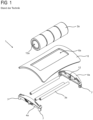
- the Figure 1 shows an exploded view of a holder 1 known from the prior art with a roller-like fascia training element.
- the fascia training element is designed as a roller-like body which is cylindrical and rotationally symmetrical.
- the fascia training element is designed as a fascia roller 2a.
- the fascia roller 2a has a cylindrical, flat surface with three evenly spaced, circumferential depressions.
- the fascia roller 2a is mounted in the holder 1 in a stationary but rotatable manner.
- the holder 1 has two oppositely positioned holding devices designed as holding plates 4a. Between the holding plates 4a there are three rotatable but stationary holding elements The holding elements are designed as cylindrical, roller-like holding shafts 3a, which are arranged parallel to one another when viewed in the longitudinal direction. The longitudinal direction of the holding shafts, i.e. their longitudinal direction of rotation, extends between the holding plates 4a.
- the holding plates 4a each have receiving units 8 in which the holding shafts 3a are rotatably mounted with their longitudinal ends.
- the holding shafts 3a are arranged in a semicircle and thus form a holder for the fascia roller 2a.
- a fastening device is designed for detachably fastening the fascia roller 2a.
- the fastening device is designed separately from the holding shafts 3a.
- the fastening device is designed as a tongue-like spring element 12 on the holding plates 4a.
- the spring elements 12 are made of elastic material. They protrude from the plane of the holding plates 4a in the direction of the opposite holding plate 4a.
- the side mounting plates 4a are also provided with feet 7, which ensure that the holder 1 is stable and non-slip/tilt-proof on a surface.
- the feet 7 are also used to hang the holder 1 in a holding device 13, see Figures 9 and 10 .
- the holder 1 also includes a cover 6, which is attached above the holding shafts 3a and partially above the fascia roller 2a.
- the cover 6 has a rectangular recess 6a from which an upper area of the fascia roller 2a protrudes.
- the cover is ergonomically rounded so that comfortable support, for example of the back, is possible on the holder 1.
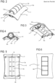
- the Figures 2 and 3 show two perspective views of the holder 1 with the fascia roll 2a according to the Figure 1 .
- the holder 1 is shown from above at an angle.
- the cover 6 and the fascia roller 2a which protrudes through the recess 6a, can be seen particularly well.
- the cover 6 protects the holding shafts 3a from contact with a user and, thanks to the ergonomic curvature, also enables comfortable storage on the training system with unhindered contact with the fascia roller 2a.
- the holder 1 is shown obliquely from below with a view of the evenly spaced holding shafts 3a.
- the fascia roll 2a rests on the holding shafts 3a in the semi-circular receptacle formed by the three holding shafts 3a. This is particularly evident in the cross section of the Figure 4 clearly visible.
- the fascia roller 2a can rotate freely in both directions around its longitudinal axis L. Due to the contact of the fascia roller 2a with the holding shafts 3a, the holding shafts 3a rotate anti-clockwise when the fascia roller 2a rotates clockwise and vice versa.
- the three holding shafts 3a are arranged below a plane through the longitudinal axis of rotation l.
- the tongue-like spring element 12 engages in the recess 12a at the longitudinal end of the fascia roller 2a and thus holds it in place in a rotatable manner.
- FIGS 5 to 8 show again different views of the holder 1 with the fascia roll 2a of the Figure 1 , namely Figure 5 a bottom view, Figure 6 a top view, Figure 7 a side view and Figure 8 a front or rear view.
- FIG 9 is a perspective view of a training system not according to the invention with a holder 1 with a fascia roller 2a according to the Figure 1 and a holding device 13.
- the holding device 13 has a plurality of evenly spaced, parallel slot-shaped recesses 13a.
- the holding device 13 is positioned vertically and can be attached to a wall, not shown here.
- the slot-shaped recesses 13a are aligned horizontally accordingly.
- the holder 1 with the fascia roller 2a is suspended in the holding device 13 by inserting the feet 7 into the recesses 13a. When inserted, there is only a forward movement. It is not necessary for the holder 1 to latch or hook into the recesses 13a, in particular the feet 7.
- the Figure 10 shows a rear view of the training system according to the Figure 9
- the distance between the feet 7 viewed in the vertical direction is significantly greater than the distance between two adjacent recesses 13a and in this embodiment corresponds to four times the distance between two adjacent recesses 13a.
- FIG 11 is a longitudinal cross-section through a known fascia roller 2a with the two lateral holding plates 4a and a fastening device designed as a spring pressure connection 9 is shown in a schematic representation.
- the spring pressure connection comprises a spring 9a, which applies a spring force to a pressure element 9b designed as a ball.
- the spring force is aligned in the direction of the longitudinal axis of the fascia roller 2a and presses the pressure element 9b from the lateral holding plate 4a in the direction of the fascia roller 2a.
- the fascia roller 2a has a spherical shell-shaped recess 9c into which the pressure element 9b is pressed.
- This spring pressure connection is formed on both longitudinal ends of the fascia roller 2a or on both holding plates 4a and forms a detachable and rotatable fastening, but secures the fascia roller 2a against unintentional release.
- FIG 12 is a longitudinal cross-section through a known fascia roller 2a with the two lateral holding plates 4a and a fastening device designed as a clip connection 10 is shown in a schematic representation.
- the clip connection comprises a bearing shell 10a on the holding plate 4a and a bearing pin 10b on the longitudinal end of the fascia roller 2a.
- the bearing pin 10b is clipped into the bearing shell 10a from above and is rotatably mounted in it.
- This clip connection is formed on both longitudinal ends of the fascia roller 2a or on both holding plates 4a and forms a detachable and rotatable fastening, but secures the fascia roller 2a against accidental release.
- FIG 13 is yet another cross-sectional view according to a section AA of the known fascia roll 2a with the clip connection 10 according to the Figure 10 shown. It is particularly shown that the bearing shell 10a partially encloses the bearing pin 10b in order to produce the clip connection 10. It can also be seen that all the holding shafts 3a are arranged below a center plane through the longitudinal axis of rotation L of the fascia roller 2a.
- FIGS. 14 to 16 show schematic representations of a holder 1 according to the invention with a ball-like fascia training element without cover.
- a cross-sectional view is shown.
- This holder 1 is used for the stationary but rotatable positioning of a fascia training element designed as a fascia ball 2b or ball.
- a lower holding device 4b and the holding balls 3b of the holder 1 are shown.
- the cover has been omitted.
- the holding device 4b is here designed as a flat surface or plate in which the four holding balls 3b are arranged.
- the holding device 4b has spherical shell-shaped depressions into which the holding balls 3b are inserted.
- the shape of the depressions is complementary to the shape and size of the holding balls 3b, with the depth of the depressions being greater than the radius of the holding balls 3b. This prevents the holding balls 3b from being accidentally released from the depressions during use.
- the holding balls 3b are arranged in a square and have a uniform design.
- the holding balls 3b are significantly smaller than the fascia ball 2b.
- the fascia ball 2b rests centrally on the holding balls 3b and can be moved freely in all directions.
- the fascia ball 2b has no contact with the holding plate 4b.
- the Figure 15 shows a side view of the bracket 1 according to the Figure 14 and the Figure 16 a perspective view.
- FIG. 17 to 20 Another embodiment of the holder 1 with a fascia ball 2b is shown. The cover has again been omitted for better clarity.
- a perspective view is shown.
- the holding device 4c has a spherical shell shape, in whose recess or receptacle the fascia ball 2b is arranged. Evenly distributed recesses are made in the spherical shell-shaped holding device 4c, into which the holding balls 3b are inserted. In this embodiment, nine holding balls 3b are used.
- a holding ball is located directly below the fascia ball 2b at the lowest point and thus stabilizes its support. This is especially important in the Figure 18 can be clearly seen.
- the retaining balls 3b of this embodiment are significantly smaller than the retaining balls 3b of the embodiment with a flat retaining device 4b. Furthermore, these smaller retaining balls 3b are arranged in significantly deeper recesses 11.
- the Figures 19 and 20 each show cross-sectional views with different cutting planes.
- a holder for a fascia training element at least comprising: at least two rotatable, stationary holding elements on which the fascia training element rests so as to be freely movable in at least one direction of rotation, and at least one holding device on which the at least two holding elements are arranged, wherein either the at least one holding device has a fastening device designed separately from the holding elements for the detachable fastening of a fascia training element designed as a roller-like body, or at least three holding elements are provided, which are designed as holding balls for a spherical fascia training element.
- the invention further relates to a fascia training element for use with the holder according to the invention, as well as a holding device for a holder according to the invention for a fascia training element, and a training system for massaging the fascia in various muscle parts of a body, at least with the holder according to the invention and a fascia training element.
Landscapes
- Health & Medical Sciences (AREA)
- Epidemiology (AREA)
- Pain & Pain Management (AREA)
- Physical Education & Sports Medicine (AREA)
- Rehabilitation Therapy (AREA)
- Life Sciences & Earth Sciences (AREA)
- Animal Behavior & Ethology (AREA)
- General Health & Medical Sciences (AREA)
- Public Health (AREA)
- Veterinary Medicine (AREA)
- Massaging Devices (AREA)
Claims (3)
- Système d'entraînement destiné à masser les fascias dans diverses zones musculaires d'un corps, ledit système d'entraînement comprenant un support (1) destiné à un élément d'entraînement de fascias (2b), un élément d'entraînement de fascias sphérique (2b) et un dispositif de retenue (13),1.1. le support (1) comportant au moins les éléments suivants :1.1.1. au moins trois éléments de retenue (3b) fixes et rotatifs sur lesquels l'élément d'entraînement de fascias repose de manière librement mobile dans au moins un sens de rotation et qui sont conçus comme des billes de retenue destinées à un élément d'entraînement de fascias sphérique (2b), et1.1.2. au moins un module de retenue (4b, 4c) sur lequel sont disposés les éléments de retenue (3b),1.2. l'élément d'entraînement de fascias (2b) étant logé dans le support (1),1.3. le support (1) pourvu de l'élément d'entraînement de fascias (2b) inséré étant positionné de manière fixe sur une base et l'utilisateur pouvant déplacer une zone musculaire par rapport au support (1) le long de l'élément d'entraînement de fascias (2b), l'élément d'entraînement de fascias (2b) tournant conjointement mais restant fixe, et1.4. un couvercle (6) étant prévu qui protège les éléments de retenue (3b) du contact d'un utilisateur,1.5. le couvercle (6) comportant un évidement (6b) par lequel moins de la moitié de l'élément d'entraînement de fascias (2b) fait saillie de sorte que l'utilisateur puisse mettre une zone musculaire en contact avec l'élément d'entraînement de fascias (2b),1.6. l'élément d'entraînement de fascias (2b) étant protégé contre un desserrage involontaire en ce que moins de la moitié de l'élément d'entraînement de fascias (2b) fait saillie par l'évidement (6b) de sorte que l'endroit le plus large de l'élément d'entraînement de fascias (2b) se trouve au-dessous du couvercle (6) et l'évidement (6b) n'est pas suffisamment grand pour que l'élément d'entraînement de fascias (2b) puisse glisser à travers, et1.7. le dispositif de retenue (13) comportant un grand nombre d'évidements (13a) dans lesquels les pieds (7) du support (1) peuvent être insérés avec un mouvement rectiligne, le dispositif de retenue (13) pouvant être fixé à une base de fixation verticale de sorte que le support (1) soit maintenu à n'importe quelle hauteur par le dispositif de retenue (13).
- Système d'entraînement selon la revendication 1 précédente, caractérisé en ce qu'exactement un module de retenue (4b, 4c) est prévu qui comporte des évidements (11) en forme de coques sphériques dans lesquels sont positionnées les billes de retenue (3b).
- Système d'entraînement selon l'une des revendications précédentes 1 à 2, caractérisé en ce que les billes de retenue (3b) sont disposées de manière à former un logement dans lequel l'élément d'entraînement de fascias (2b) est positionné et est librement mobile dans tous les sens de rotation par rapport aux billes de retenue (3b).
Priority Applications (1)
| Application Number | Priority Date | Filing Date | Title |
|---|---|---|---|
| EP21183716.6A EP4000581B1 (fr) | 2020-11-20 | 2020-11-20 | Support d'un élément d'entrainement fascial, élément d'entrainement fascial, et dispositif de maintien et système d'entrainement |
Applications Claiming Priority (2)
| Application Number | Priority Date | Filing Date | Title |
|---|---|---|---|
| EP20208811.8A EP4000580B1 (fr) | 2020-11-20 | 2020-11-20 | Support d'un élément d'entraînement fascial, élément d'entraînement fascial, et dispositif de maintien et système d'entraînement |
| EP21183716.6A EP4000581B1 (fr) | 2020-11-20 | 2020-11-20 | Support d'un élément d'entrainement fascial, élément d'entrainement fascial, et dispositif de maintien et système d'entrainement |
Related Parent Applications (2)
| Application Number | Title | Priority Date | Filing Date |
|---|---|---|---|
| EP20208811.8A Division EP4000580B1 (fr) | 2020-11-20 | 2020-11-20 | Support d'un élément d'entraînement fascial, élément d'entraînement fascial, et dispositif de maintien et système d'entraînement |
| EP20208811.8A Division-Into EP4000580B1 (fr) | 2020-11-20 | 2020-11-20 | Support d'un élément d'entraînement fascial, élément d'entraînement fascial, et dispositif de maintien et système d'entraînement |
Publications (2)
| Publication Number | Publication Date |
|---|---|
| EP4000581A1 EP4000581A1 (fr) | 2022-05-25 |
| EP4000581B1 true EP4000581B1 (fr) | 2024-07-24 |
Family
ID=73543057
Family Applications (2)
| Application Number | Title | Priority Date | Filing Date |
|---|---|---|---|
| EP21183716.6A Active EP4000581B1 (fr) | 2020-11-20 | 2020-11-20 | Support d'un élément d'entrainement fascial, élément d'entrainement fascial, et dispositif de maintien et système d'entrainement |
| EP20208811.8A Active EP4000580B1 (fr) | 2020-11-20 | 2020-11-20 | Support d'un élément d'entraînement fascial, élément d'entraînement fascial, et dispositif de maintien et système d'entraînement |
Family Applications After (1)
| Application Number | Title | Priority Date | Filing Date |
|---|---|---|---|
| EP20208811.8A Active EP4000580B1 (fr) | 2020-11-20 | 2020-11-20 | Support d'un élément d'entraînement fascial, élément d'entraînement fascial, et dispositif de maintien et système d'entraînement |
Country Status (1)
| Country | Link |
|---|---|
| EP (2) | EP4000581B1 (fr) |
Family Cites Families (9)
| Publication number | Priority date | Publication date | Assignee | Title |
|---|---|---|---|---|
| US6309331B1 (en) * | 1999-02-12 | 2001-10-30 | Jean-Guy Raymond | Abdominal exerciser device |
| US6669611B2 (en) * | 2000-02-11 | 2003-12-30 | Jean-Guy Raymond | Abdominal exerciser device |
| US7169120B2 (en) * | 2004-05-11 | 2007-01-30 | Murdock Matthew L | Device and method for providing a massage |
| US20120005818A1 (en) * | 2010-07-09 | 2012-01-12 | Coelho Nathanael S | Solar powered hot tub |
| US20150328080A1 (en) * | 2014-05-15 | 2015-11-19 | Ian Q. Ryan | Fascial Release Ball |
| DE102015004133A1 (de) | 2015-03-31 | 2016-10-06 | five-Konzept GmbH & Co. KG | Faszien-Trainingsgerät mit einer Faszialrolle |
| US20190231636A1 (en) * | 2016-02-16 | 2019-08-01 | Gelliflex Holdings, Llc | Ladder-Style Modular Self-Massage Apparatus |
| DE202016006426U1 (de) | 2016-10-07 | 2016-11-17 | Marcus Mutz | Faszien Massageroller |
| GB2570142A (en) * | 2018-01-12 | 2019-07-17 | Paul Lark David | Ball supported massage instrument |
-
2020
- 2020-11-20 EP EP21183716.6A patent/EP4000581B1/fr active Active
- 2020-11-20 EP EP20208811.8A patent/EP4000580B1/fr active Active
Also Published As
| Publication number | Publication date |
|---|---|
| EP4000581A1 (fr) | 2022-05-25 |
| EP4000580B1 (fr) | 2024-07-24 |
| EP4000580A1 (fr) | 2022-05-25 |
Similar Documents
| Publication | Publication Date | Title |
|---|---|---|
| DE20200790U1 (de) | Massageaufsatz für ein motorisch angetriebenes Fußpflegegerät | |
| DE2319591C2 (de) | Medizinischer Apparat | |
| EP3124003B1 (fr) | Dispositif therapeutique de traitement des collages de fascias chez une personne | |
| DE202018102210U1 (de) | Verstellmechanismus und Hebevorrichtung, welche den Verstellmechanismus umfasst | |
| EP3536298B1 (fr) | Dispositif de massage | |
| DE69010174T2 (de) | Fingertrainingsgerät. | |
| EP4000580B1 (fr) | Support d'un élément d'entraînement fascial, élément d'entraînement fascial, et dispositif de maintien et système d'entraînement | |
| DE202015100830U1 (de) | Trainingsgerät für den menschlichen Körper | |
| DE202015002149U1 (de) | Trainingsgerät | |
| DE202012104957U1 (de) | Verstellbarer Inlineskate | |
| EP3609460B1 (fr) | Appareil d'entraînement à la mobilité | |
| LU102266B1 (de) | Therapiegerät zur äusseren Behandlung des menschlichen und tierischen Körpers | |
| DE102021211757B4 (de) | Trainingsgerät zur komplexen Muskelbeanspruchung im Kraftsport | |
| DE102016113775B3 (de) | Rückenmassagegerät | |
| DE102020128244A1 (de) | Vorrichtung zur Selbstmassage | |
| DE3600659C2 (fr) | ||
| DE10227612B4 (de) | Fahrrad-Flaschenhalter | |
| DE1031696B (de) | Geschicklichkeitsspielgeraet, bestehend aus einem mittels Handgriff gefuehrten Gestell und einem daran abrollbaren Laufkoerper | |
| DE1627458C3 (de) | Abstützkopf | |
| DE202012100704U1 (de) | Bauchtrainingsgerät mit winkelverstellbarem, teleskopischem Fussgestell | |
| WO2018127326A1 (fr) | Porte-électrodes portable | |
| DE202006015225U1 (de) | Massagevorrichtung | |
| EP1033105A2 (fr) | Dispositif de nettoyage | |
| DE202022101645U1 (de) | Therapeutisches Trainings- und Behandlungsgerät | |
| DE20002582U1 (de) | Sportgerät |
Legal Events
| Date | Code | Title | Description |
|---|---|---|---|
| PUAI | Public reference made under article 153(3) epc to a published international application that has entered the european phase |
Free format text: ORIGINAL CODE: 0009012 |
|
| STAA | Information on the status of an ep patent application or granted ep patent |
Free format text: STATUS: THE APPLICATION HAS BEEN PUBLISHED |
|
| AC | Divisional application: reference to earlier application |
Ref document number: 4000580 Country of ref document: EP Kind code of ref document: P |
|
| AK | Designated contracting states |
Kind code of ref document: A1 Designated state(s): AL AT BE BG CH CY CZ DE DK EE ES FI FR GB GR HR HU IE IS IT LI LT LU LV MC MK MT NL NO PL PT RO RS SE SI SK SM TR |
|
| STAA | Information on the status of an ep patent application or granted ep patent |
Free format text: STATUS: REQUEST FOR EXAMINATION WAS MADE |
|
| 17P | Request for examination filed |
Effective date: 20220629 |
|
| RBV | Designated contracting states (corrected) |
Designated state(s): AL AT BE BG CH CY CZ DE DK EE ES FI FR GB GR HR HU IE IS IT LI LT LU LV MC MK MT NL NO PL PT RO RS SE SI SK SM TR |
|
| GRAP | Despatch of communication of intention to grant a patent |
Free format text: ORIGINAL CODE: EPIDOSNIGR1 |
|
| STAA | Information on the status of an ep patent application or granted ep patent |
Free format text: STATUS: GRANT OF PATENT IS INTENDED |
|
| INTG | Intention to grant announced |
Effective date: 20240315 |
|
| RAP3 | Party data changed (applicant data changed or rights of an application transferred) |
Owner name: MAX FITNESS GMBH |
|
| GRAS | Grant fee paid |
Free format text: ORIGINAL CODE: EPIDOSNIGR3 |
|
| GRAA | (expected) grant |
Free format text: ORIGINAL CODE: 0009210 |
|
| STAA | Information on the status of an ep patent application or granted ep patent |
Free format text: STATUS: THE PATENT HAS BEEN GRANTED |
|
| AC | Divisional application: reference to earlier application |
Ref document number: 4000580 Country of ref document: EP Kind code of ref document: P |
|
| AK | Designated contracting states |
Kind code of ref document: B1 Designated state(s): AL AT BE BG CH CY CZ DE DK EE ES FI FR GB GR HR HU IE IS IT LI LT LU LV MC MK MT NL NO PL PT RO RS SE SI SK SM TR |
|
| REG | Reference to a national code |
Ref country code: GB Ref legal event code: FG4D Free format text: NOT ENGLISH |
|
| REG | Reference to a national code |
Ref country code: CH Ref legal event code: EP |
|
| REG | Reference to a national code |
Ref country code: DE Ref legal event code: R096 Ref document number: 502020008705 Country of ref document: DE |
|
| REG | Reference to a national code |
Ref country code: IE Ref legal event code: FG4D Free format text: LANGUAGE OF EP DOCUMENT: GERMAN |
|
| P01 | Opt-out of the competence of the unified patent court (upc) registered |
Free format text: CASE NUMBER: APP_43430/2024 Effective date: 20240725 |
|
| REG | Reference to a national code |
Ref country code: LT Ref legal event code: MG9D |
|
| REG | Reference to a national code |
Ref country code: NL Ref legal event code: MP Effective date: 20240724 |
|
| PG25 | Lapsed in a contracting state [announced via postgrant information from national office to epo] |
Ref country code: PT Free format text: LAPSE BECAUSE OF FAILURE TO SUBMIT A TRANSLATION OF THE DESCRIPTION OR TO PAY THE FEE WITHIN THE PRESCRIBED TIME-LIMIT Effective date: 20241125 |
|
| PG25 | Lapsed in a contracting state [announced via postgrant information from national office to epo] |
Ref country code: NL Free format text: LAPSE BECAUSE OF FAILURE TO SUBMIT A TRANSLATION OF THE DESCRIPTION OR TO PAY THE FEE WITHIN THE PRESCRIBED TIME-LIMIT Effective date: 20240724 |
|
| PG25 | Lapsed in a contracting state [announced via postgrant information from national office to epo] |
Ref country code: PT Free format text: LAPSE BECAUSE OF FAILURE TO SUBMIT A TRANSLATION OF THE DESCRIPTION OR TO PAY THE FEE WITHIN THE PRESCRIBED TIME-LIMIT Effective date: 20241125 Ref country code: NL Free format text: LAPSE BECAUSE OF FAILURE TO SUBMIT A TRANSLATION OF THE DESCRIPTION OR TO PAY THE FEE WITHIN THE PRESCRIBED TIME-LIMIT Effective date: 20240724 |
|
| PG25 | Lapsed in a contracting state [announced via postgrant information from national office to epo] |
Ref country code: NO Free format text: LAPSE BECAUSE OF FAILURE TO SUBMIT A TRANSLATION OF THE DESCRIPTION OR TO PAY THE FEE WITHIN THE PRESCRIBED TIME-LIMIT Effective date: 20241024 |
|
| PG25 | Lapsed in a contracting state [announced via postgrant information from national office to epo] |
Ref country code: FI Free format text: LAPSE BECAUSE OF FAILURE TO SUBMIT A TRANSLATION OF THE DESCRIPTION OR TO PAY THE FEE WITHIN THE PRESCRIBED TIME-LIMIT Effective date: 20240724 Ref country code: PL Free format text: LAPSE BECAUSE OF FAILURE TO SUBMIT A TRANSLATION OF THE DESCRIPTION OR TO PAY THE FEE WITHIN THE PRESCRIBED TIME-LIMIT Effective date: 20240724 Ref country code: GR Free format text: LAPSE BECAUSE OF FAILURE TO SUBMIT A TRANSLATION OF THE DESCRIPTION OR TO PAY THE FEE WITHIN THE PRESCRIBED TIME-LIMIT Effective date: 20241025 |
|
| PG25 | Lapsed in a contracting state [announced via postgrant information from national office to epo] |
Ref country code: BG Free format text: LAPSE BECAUSE OF FAILURE TO SUBMIT A TRANSLATION OF THE DESCRIPTION OR TO PAY THE FEE WITHIN THE PRESCRIBED TIME-LIMIT Effective date: 20240724 |
|
| PG25 | Lapsed in a contracting state [announced via postgrant information from national office to epo] |
Ref country code: LV Free format text: LAPSE BECAUSE OF FAILURE TO SUBMIT A TRANSLATION OF THE DESCRIPTION OR TO PAY THE FEE WITHIN THE PRESCRIBED TIME-LIMIT Effective date: 20240724 |
|
| PG25 | Lapsed in a contracting state [announced via postgrant information from national office to epo] |
Ref country code: IS Free format text: LAPSE BECAUSE OF FAILURE TO SUBMIT A TRANSLATION OF THE DESCRIPTION OR TO PAY THE FEE WITHIN THE PRESCRIBED TIME-LIMIT Effective date: 20241124 |
|
| PG25 | Lapsed in a contracting state [announced via postgrant information from national office to epo] |
Ref country code: HR Free format text: LAPSE BECAUSE OF FAILURE TO SUBMIT A TRANSLATION OF THE DESCRIPTION OR TO PAY THE FEE WITHIN THE PRESCRIBED TIME-LIMIT Effective date: 20240724 |
|
| PG25 | Lapsed in a contracting state [announced via postgrant information from national office to epo] |
Ref country code: RS Free format text: LAPSE BECAUSE OF FAILURE TO SUBMIT A TRANSLATION OF THE DESCRIPTION OR TO PAY THE FEE WITHIN THE PRESCRIBED TIME-LIMIT Effective date: 20241024 Ref country code: ES Free format text: LAPSE BECAUSE OF FAILURE TO SUBMIT A TRANSLATION OF THE DESCRIPTION OR TO PAY THE FEE WITHIN THE PRESCRIBED TIME-LIMIT Effective date: 20240724 |
|
| PG25 | Lapsed in a contracting state [announced via postgrant information from national office to epo] |
Ref country code: RS Free format text: LAPSE BECAUSE OF FAILURE TO SUBMIT A TRANSLATION OF THE DESCRIPTION OR TO PAY THE FEE WITHIN THE PRESCRIBED TIME-LIMIT Effective date: 20241024 Ref country code: PL Free format text: LAPSE BECAUSE OF FAILURE TO SUBMIT A TRANSLATION OF THE DESCRIPTION OR TO PAY THE FEE WITHIN THE PRESCRIBED TIME-LIMIT Effective date: 20240724 Ref country code: NO Free format text: LAPSE BECAUSE OF FAILURE TO SUBMIT A TRANSLATION OF THE DESCRIPTION OR TO PAY THE FEE WITHIN THE PRESCRIBED TIME-LIMIT Effective date: 20241024 Ref country code: LV Free format text: LAPSE BECAUSE OF FAILURE TO SUBMIT A TRANSLATION OF THE DESCRIPTION OR TO PAY THE FEE WITHIN THE PRESCRIBED TIME-LIMIT Effective date: 20240724 Ref country code: IS Free format text: LAPSE BECAUSE OF FAILURE TO SUBMIT A TRANSLATION OF THE DESCRIPTION OR TO PAY THE FEE WITHIN THE PRESCRIBED TIME-LIMIT Effective date: 20241124 Ref country code: HR Free format text: LAPSE BECAUSE OF FAILURE TO SUBMIT A TRANSLATION OF THE DESCRIPTION OR TO PAY THE FEE WITHIN THE PRESCRIBED TIME-LIMIT Effective date: 20240724 Ref country code: GR Free format text: LAPSE BECAUSE OF FAILURE TO SUBMIT A TRANSLATION OF THE DESCRIPTION OR TO PAY THE FEE WITHIN THE PRESCRIBED TIME-LIMIT Effective date: 20241025 Ref country code: FI Free format text: LAPSE BECAUSE OF FAILURE TO SUBMIT A TRANSLATION OF THE DESCRIPTION OR TO PAY THE FEE WITHIN THE PRESCRIBED TIME-LIMIT Effective date: 20240724 Ref country code: ES Free format text: LAPSE BECAUSE OF FAILURE TO SUBMIT A TRANSLATION OF THE DESCRIPTION OR TO PAY THE FEE WITHIN THE PRESCRIBED TIME-LIMIT Effective date: 20240724 Ref country code: BG Free format text: LAPSE BECAUSE OF FAILURE TO SUBMIT A TRANSLATION OF THE DESCRIPTION OR TO PAY THE FEE WITHIN THE PRESCRIBED TIME-LIMIT Effective date: 20240724 |
|
| PG25 | Lapsed in a contracting state [announced via postgrant information from national office to epo] |
Ref country code: RO Free format text: LAPSE BECAUSE OF FAILURE TO SUBMIT A TRANSLATION OF THE DESCRIPTION OR TO PAY THE FEE WITHIN THE PRESCRIBED TIME-LIMIT Effective date: 20240724 Ref country code: SM Free format text: LAPSE BECAUSE OF FAILURE TO SUBMIT A TRANSLATION OF THE DESCRIPTION OR TO PAY THE FEE WITHIN THE PRESCRIBED TIME-LIMIT Effective date: 20240724 Ref country code: DK Free format text: LAPSE BECAUSE OF FAILURE TO SUBMIT A TRANSLATION OF THE DESCRIPTION OR TO PAY THE FEE WITHIN THE PRESCRIBED TIME-LIMIT Effective date: 20240724 |
|
| PG25 | Lapsed in a contracting state [announced via postgrant information from national office to epo] |
Ref country code: EE Free format text: LAPSE BECAUSE OF FAILURE TO SUBMIT A TRANSLATION OF THE DESCRIPTION OR TO PAY THE FEE WITHIN THE PRESCRIBED TIME-LIMIT Effective date: 20240724 |
|
| PG25 | Lapsed in a contracting state [announced via postgrant information from national office to epo] |
Ref country code: CZ Free format text: LAPSE BECAUSE OF FAILURE TO SUBMIT A TRANSLATION OF THE DESCRIPTION OR TO PAY THE FEE WITHIN THE PRESCRIBED TIME-LIMIT Effective date: 20240724 |
|
| REG | Reference to a national code |
Ref country code: DE Ref legal event code: R097 Ref document number: 502020008705 Country of ref document: DE |
|
| PG25 | Lapsed in a contracting state [announced via postgrant information from national office to epo] |
Ref country code: IT Free format text: LAPSE BECAUSE OF FAILURE TO SUBMIT A TRANSLATION OF THE DESCRIPTION OR TO PAY THE FEE WITHIN THE PRESCRIBED TIME-LIMIT Effective date: 20240724 Ref country code: SK Free format text: LAPSE BECAUSE OF FAILURE TO SUBMIT A TRANSLATION OF THE DESCRIPTION OR TO PAY THE FEE WITHIN THE PRESCRIBED TIME-LIMIT Effective date: 20240724 |
|
| PLBE | No opposition filed within time limit |
Free format text: ORIGINAL CODE: 0009261 |
|
| STAA | Information on the status of an ep patent application or granted ep patent |
Free format text: STATUS: NO OPPOSITION FILED WITHIN TIME LIMIT |
|
| 26N | No opposition filed |
Effective date: 20250425 |
|
| PG25 | Lapsed in a contracting state [announced via postgrant information from national office to epo] |
Ref country code: MC Free format text: LAPSE BECAUSE OF FAILURE TO SUBMIT A TRANSLATION OF THE DESCRIPTION OR TO PAY THE FEE WITHIN THE PRESCRIBED TIME-LIMIT Effective date: 20240724 |
|
| PG25 | Lapsed in a contracting state [announced via postgrant information from national office to epo] |
Ref country code: LU Free format text: LAPSE BECAUSE OF NON-PAYMENT OF DUE FEES Effective date: 20241120 |
|
| GBPC | Gb: european patent ceased through non-payment of renewal fee |
Effective date: 20241120 |
|
| REG | Reference to a national code |
Ref country code: BE Ref legal event code: MM Effective date: 20241130 |
|
| PG25 | Lapsed in a contracting state [announced via postgrant information from national office to epo] |
Ref country code: SE Free format text: LAPSE BECAUSE OF FAILURE TO SUBMIT A TRANSLATION OF THE DESCRIPTION OR TO PAY THE FEE WITHIN THE PRESCRIBED TIME-LIMIT Effective date: 20240724 |
|
| PG25 | Lapsed in a contracting state [announced via postgrant information from national office to epo] |
Ref country code: BE Free format text: LAPSE BECAUSE OF NON-PAYMENT OF DUE FEES Effective date: 20241130 Ref country code: GB Free format text: LAPSE BECAUSE OF NON-PAYMENT OF DUE FEES Effective date: 20241120 |
|
| PG25 | Lapsed in a contracting state [announced via postgrant information from national office to epo] |
Ref country code: FR Free format text: LAPSE BECAUSE OF NON-PAYMENT OF DUE FEES Effective date: 20241130 |
|
| PG25 | Lapsed in a contracting state [announced via postgrant information from national office to epo] |
Ref country code: IE Free format text: LAPSE BECAUSE OF NON-PAYMENT OF DUE FEES Effective date: 20241120 |
|
| REG | Reference to a national code |
Ref country code: CH Ref legal event code: U11 Free format text: ST27 STATUS EVENT CODE: U-0-0-U10-U11 (AS PROVIDED BY THE NATIONAL OFFICE) Effective date: 20251201 |
|
| PGFP | Annual fee paid to national office [announced via postgrant information from national office to epo] |
Ref country code: DE Payment date: 20251119 Year of fee payment: 6 |
|
| PGFP | Annual fee paid to national office [announced via postgrant information from national office to epo] |
Ref country code: AT Payment date: 20251119 Year of fee payment: 6 |
|
| PGFP | Annual fee paid to national office [announced via postgrant information from national office to epo] |
Ref country code: CH Payment date: 20251201 Year of fee payment: 6 |
|
| PG25 | Lapsed in a contracting state [announced via postgrant information from national office to epo] |
Ref country code: HU Free format text: LAPSE BECAUSE OF FAILURE TO SUBMIT A TRANSLATION OF THE DESCRIPTION OR TO PAY THE FEE WITHIN THE PRESCRIBED TIME-LIMIT; INVALID AB INITIO Effective date: 20201120 |
|
| PG25 | Lapsed in a contracting state [announced via postgrant information from national office to epo] |
Ref country code: CY Free format text: LAPSE BECAUSE OF FAILURE TO SUBMIT A TRANSLATION OF THE DESCRIPTION OR TO PAY THE FEE WITHIN THE PRESCRIBED TIME-LIMIT; INVALID AB INITIO Effective date: 20201120 |