EP4000687A1 - Gerät zur behandlung mit fokussiertem ultraschall niedriger intensität - Google Patents
Gerät zur behandlung mit fokussiertem ultraschall niedriger intensität Download PDFInfo
- Publication number
- EP4000687A1 EP4000687A1 EP21202800.5A EP21202800A EP4000687A1 EP 4000687 A1 EP4000687 A1 EP 4000687A1 EP 21202800 A EP21202800 A EP 21202800A EP 4000687 A1 EP4000687 A1 EP 4000687A1
- Authority
- EP
- European Patent Office
- Prior art keywords
- ultrasound
- transducer
- arm
- low
- intensity focused
- Prior art date
- Legal status (The legal status is an assumption and is not a legal conclusion. Google has not performed a legal analysis and makes no representation as to the accuracy of the status listed.)
- Withdrawn
Links
Images



Classifications
-
- A—HUMAN NECESSITIES
- A61—MEDICAL OR VETERINARY SCIENCE; HYGIENE
- A61N—ELECTROTHERAPY; MAGNETOTHERAPY; RADIATION THERAPY; ULTRASOUND THERAPY
- A61N7/00—Ultrasound therapy
-
- A—HUMAN NECESSITIES
- A61—MEDICAL OR VETERINARY SCIENCE; HYGIENE
- A61N—ELECTROTHERAPY; MAGNETOTHERAPY; RADIATION THERAPY; ULTRASOUND THERAPY
- A61N7/00—Ultrasound therapy
- A61N7/02—Localised ultrasound hyperthermia
-
- A—HUMAN NECESSITIES
- A61—MEDICAL OR VETERINARY SCIENCE; HYGIENE
- A61B—DIAGNOSIS; SURGERY; IDENTIFICATION
- A61B90/00—Instruments, implements or accessories specially adapted for surgery or diagnosis and not covered by any of the groups A61B1/00 - A61B50/00, e.g. for luxation treatment or for protecting wound edges
- A61B90/50—Supports for surgical instruments, e.g. articulated arms
-
- A—HUMAN NECESSITIES
- A61—MEDICAL OR VETERINARY SCIENCE; HYGIENE
- A61B—DIAGNOSIS; SURGERY; IDENTIFICATION
- A61B90/00—Instruments, implements or accessories specially adapted for surgery or diagnosis and not covered by any of the groups A61B1/00 - A61B50/00, e.g. for luxation treatment or for protecting wound edges
- A61B90/39—Markers, e.g. radio-opaque or breast lesions markers
- A61B2090/3983—Reference marker arrangements for use with image guided surgery
-
- A—HUMAN NECESSITIES
- A61—MEDICAL OR VETERINARY SCIENCE; HYGIENE
- A61B—DIAGNOSIS; SURGERY; IDENTIFICATION
- A61B90/00—Instruments, implements or accessories specially adapted for surgery or diagnosis and not covered by any of the groups A61B1/00 - A61B50/00, e.g. for luxation treatment or for protecting wound edges
- A61B90/50—Supports for surgical instruments, e.g. articulated arms
- A61B2090/502—Headgear, e.g. helmet, spectacles
-
- A—HUMAN NECESSITIES
- A61—MEDICAL OR VETERINARY SCIENCE; HYGIENE
- A61N—ELECTROTHERAPY; MAGNETOTHERAPY; RADIATION THERAPY; ULTRASOUND THERAPY
- A61N7/00—Ultrasound therapy
- A61N2007/0004—Applications of ultrasound therapy
- A61N2007/0021—Neural system treatment
- A61N2007/0026—Stimulation of nerve tissue
-
- A—HUMAN NECESSITIES
- A61—MEDICAL OR VETERINARY SCIENCE; HYGIENE
- A61N—ELECTROTHERAPY; MAGNETOTHERAPY; RADIATION THERAPY; ULTRASOUND THERAPY
- A61N7/00—Ultrasound therapy
- A61N2007/0056—Beam shaping elements
-
- A—HUMAN NECESSITIES
- A61—MEDICAL OR VETERINARY SCIENCE; HYGIENE
- A61N—ELECTROTHERAPY; MAGNETOTHERAPY; RADIATION THERAPY; ULTRASOUND THERAPY
- A61N7/00—Ultrasound therapy
- A61N2007/0056—Beam shaping elements
- A61N2007/006—Lenses
-
- A—HUMAN NECESSITIES
- A61—MEDICAL OR VETERINARY SCIENCE; HYGIENE
- A61N—ELECTROTHERAPY; MAGNETOTHERAPY; RADIATION THERAPY; ULTRASOUND THERAPY
- A61N7/00—Ultrasound therapy
- A61N2007/0078—Ultrasound therapy with multiple treatment transducers
-
- A—HUMAN NECESSITIES
- A61—MEDICAL OR VETERINARY SCIENCE; HYGIENE
- A61N—ELECTROTHERAPY; MAGNETOTHERAPY; RADIATION THERAPY; ULTRASOUND THERAPY
- A61N7/00—Ultrasound therapy
- A61N2007/0086—Beam steering
-
- A—HUMAN NECESSITIES
- A61—MEDICAL OR VETERINARY SCIENCE; HYGIENE
- A61N—ELECTROTHERAPY; MAGNETOTHERAPY; RADIATION THERAPY; ULTRASOUND THERAPY
- A61N7/00—Ultrasound therapy
- A61N2007/0086—Beam steering
- A61N2007/0091—Beam steering with moving parts, e.g. transducers, lenses, reflectors
-
- A—HUMAN NECESSITIES
- A61—MEDICAL OR VETERINARY SCIENCE; HYGIENE
- A61N—ELECTROTHERAPY; MAGNETOTHERAPY; RADIATION THERAPY; ULTRASOUND THERAPY
- A61N7/00—Ultrasound therapy
- A61N7/02—Localised ultrasound hyperthermia
- A61N2007/025—Localised ultrasound hyperthermia interstitial
Definitions
- a technology related to a low-intensity focused ultrasound treatment device is disclosed.
- Ultrasound stimulation therapy that can stimulate brain lesions without a physical invasive process is known.
- the transcranial direct current stimulation technique or the transcranial magnetic stimulation technique has a problem that it is difficult to treat deep brain and cannot treat a precise area.
- Low intensity focused ultrasound technology can safely activate or inhibit neurons' activity in specific areas of the deep brain without side effects.
- low-intensity focused ultrasound technology can treat mental disorders such as depressive disorder and schizophrenia and chronic nervous system diseases such as Alzheimer's and epilepsy.
- the low-intensity focused ultrasound technology induces stable cavitation for microbubbles, thereby temporarily opening the cerebrovascular barrier. Accordingly, various therapeutic agents for brain diseases can be delivered to the brain.
- the beamforming control algorithm applies voltages having different amplitudes or phases to each of the transducer elements forming the array.
- ultrasonic application equipment e.g., ultrasonic generator, linear amplifier, electric signal generator, waveform modulator, wiring unit, etc.
- drive signals e.g., amplitude, phase control
- circuit for driving becomes complicated, and the driving control algorithm and the error control algorithm are also complicated. Accordingly, there is a problem that the cost of manufacturing the low-intensity focused ultrasound treatment apparatus increases.
- the multi-array transducer technology it is possible to focus on multiple regions using a single multi-array transducer by using phase-modulated beam forming. There is a problem that the location is changed. That is, a multi-array transducer places many small transducers in a semicircular structure larger than the brain. When targeting the brain's cortical part, for example, the upper part of the brain, the angle for ultrasonic incidence is not made to the target for the transducer located in a specific part of the multi-array. Accordingly, the number of multi-array transducers that transmit effective ultrasonic energy is reduced, resulting in a difficult problem in that effective ultrasonic application.
- the ultrasonic transducer and the patient's skull must be in close contact with each other and fixed.
- a skull positioning device has substantially fixed the patient's skull in a single position. Accordingly, the patient cannot move his/her head at all by the skull position fixing device during the ultrasound treatment . Therefore, the patient may feel uncomfortable.
- the proposed invention aims to provide a low-intensity focused ultrasound treatment apparatus capable of reducing manufacturing and maintenance costs.
- Another purpose of the proposed invention is to provide a low-intensity focused ultrasound treatment apparatus.
- An effective ultrasound focusing region does not differ depending on the treatment site.
- another purpose of the proposed invention is to provide a low-intensity focused ultrasound treatment apparatus in which an ultrasonic application device can be simplified.
- Another purpose of the proposed invention is to provide a low-intensity focused ultrasound treatment apparatus.
- a single-element ultrasound transducer capable of precisely positioning various treatment areas of a deep brain region is applied.
- Another purpose of the proposed invention is to provide a low-intensity focused ultrasound treatment apparatus capable of adjusting the position and various postures of a single-element ultrasound transducer concerning a patient's head.
- Another purpose of the proposed invention is to provide a low-intensity focused ultrasound treatment apparatus comprising an ultrasonic transducer capable of slightly moving a patient's head during ultrasound treatment and a contact and fixation configuration between the patient's skull.
- a single-element ultrasound transducer with a focus area, a focus distance, and an output intensity characteristic capable of safe treatment for a patient's deep brain are applied to low-intensity focused ultrasound treatment apparatus.
- a single-element ultrasonic transducer applied to a low-intensity focused ultrasound treatment device is plural for each focusing distance.
- One of multiple single-element ultrasonic transducers having a corresponding focusing distance can be replaced.
- the device ultrasonic transducer has a detachable structure.
- an ultrasonic gel layer for adjusting the focusing distance is placed on the bottom of the single element ultrasonic transducer.
- multiple band hook portions are formed on a single element ultrasonic transducer, and multiple fixed band portions fixed to each of multiple band hook portions are formed in the headband portion mounted on the patient's skull.
- the articulated manipulation unit is detachably coupled to one of multiple single-element transducers. The articulated manipulation unit precisely adjusts the position and posture of the single element ultrasonic transducer.
- the free articulating Arm included in the multi-joint manipulation unit adjusts the height and front-rear position of the single element ultrasonic transducer, and the manipulation Arm is included in the multi-joint manipulation unit is used in the single element ultrasonic transducer that is detachable and rotatable in all directions.
- a single element ultrasound transducer capable of precisely positioning various treatment areas of a deep brain region is applied.
- a low-intensity focused ultrasound treatment apparatus capable of adjusting the position and various postures of a single-element ultrasound transducer concerning a patient's head.
- a low-intensity focused ultrasound treatment apparatus including an ultrasonic transducer capable of slightly moving a patient's head during ultrasound treatment and a configuration of close contact fixation between the patient's head.
- Drawing 1 shows the focused ultrasound beam output characteristics of a single-element ultrasound transducer according to an embodiment.
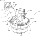
- Drawing 2 shows a structure in which an articulated operator and a single-element ultrasound transducer are combined according to an embodiment. It is a perspective view and will be described below concerning the above drawings.
- the focusing region diameter (120) at the maximum acoustic intensity point (110) in the focal region (100) is 6mm to 9mm; an ultrasound transducer (1000) outputting a low intensity focused ultrasound beam (140) having a focal length (130) of 30 mm to 80 mm from the surface (1000) to the maximum acoustic intensity point (110), and a single-element ultrasound transducer (1000), and includes a transducer marker (2000)that provides position and posture information of the single-element ultrasound transducer (1000).
- a single-element ultrasound transducer (1000) is applied to a low intensity focused ultrasonic treatment device.
- the single-element ultrasound transducer (1000) has a focused region (100), a focused region diameter (120), a Focal length (130), and low-intensity output strength characteristics that enable safe treatment of a patient's deep brain.
- the focused region diameter (120) at the maximum acoustic intensity point (110) in the focused region (100) where the ultrasound beam output from the single-element ultrasound transducer (1000) is focused is 6mm to 9mm.
- the Focal length (130) from the surface of the single-element ultrasound transducer (1000) to the maximum acoustic intensity point (110) is 30mm to 80mm.
- the acoustic strength of the ultrasound beam output by the single-element ultrasound transducer (1000) is low intensity, so that safe treatment for the patient's deep brain is possible.
- the acoustic strength (acoustic intensity) in the focused region (100) of the ultrasound beam output from the single-element ultrasound transducer (1000) maybe 50 watts per square centimeter (50 W/cm 2 ) or less.
- the low intensity focused ultrasonic treatment device is fixed to the single-element ultrasound transducer (1000) to provide position and posture information of the single-element ultrasound transducer (1000).
- the transducer marker (2000) provides position and posture information of the single-element ultrasound transducer (1000).
- the location tracking device (not shown) included in the low intensity focused ultrasonic treatment device recognizes the spatial position and posture of the single-element ultrasound transducer (1000) provided by the transducer marker (2000) provides low intensity focused ultrasonic treatment. Position and posture may be displayed on a monitor (not shown) included in the device.
- the user may move the single-element ultrasound transducer (1000) to match the transducer focused region (100) to the treatment area inside the patient's brain.
- a registration step to match the patient's physical space with a space-based on a three-dimensional image acquired from CT/MRI may be performed.
- the single-element ultrasound transducer (1000) can be moved to match the transducer focused region (100) to the treatment area inside the patient's brain.
- the matching step of the image space and the actual space corresponds to a technique known in the art, and thus a more detailed description thereof will be omitted.
- Drawing 3 is a cross-sectional view showing a single-element ultrasound transducer according to an embodiment and will be described concerning Drawing 3 below.
- a single-element ultrasound transducer (1000) includes an electrode (1400) for applying a voltage, a single piezoelectric element (1200) for outputting a low-intensity ultrasound beam, spherical lens (1300) for focusing a low-intensity ultrasound beam, a connector (1500) for electrically connecting an external control cable (not shown) and an electrode (1400), a single piezoelectric element (1200), a spherical lens (1300), and a transducer housing (1100) in which the connector (1500) is placed.
- a single piezoelectric element (1200) outputting a low-intensity ultrasound beam, and a spherical lens (1300) focusing a low-intensity ultrasound beam below the output surface of the ultrasound beam of the single piezoelectric element (1200) are transducers. It is placed within the housing (1100).
- the ultrasound beam output's output characteristics by the single piezoelectric element (1200) and the spherical lens ((130)0) are as described in Drawing 1 .
- the single-element ultrasound transducer (1000) may further include a connector cover (1600) for protecting the connector (1500) (see Drawing 2 ).
- the connector cover (1600) protects the portion of the connector (1500) exposed to the outside of the transducer housing (1100).
- Drawing 2 shows that the connector cover (1600) has an approximately " ⁇ " shape and may have a through-hole therein.
- An external control cable (not shown) may be electrically connected to the connector (1500) through a through-hole
- Drawing 4 is a perspective view showing a low intensity focused ultrasonic treatment device according to an embodiment. It will be described below in Drawing 4 .
- the low intensity focused ultrasonic treatment device is an articulated operator coupled to the single-element ultrasound transducer (1000) so that the position and posture of the single-element ultrasound transducer can be adjusted (3000) may be further included.
- the single-element ultrasound transducer (1000) may be coupled to an articulated operator (3000).
- the articulated operator (3000) includes multiple joints, and a medical practitioner can control multiple joints coupled to the single-element transducer (1000). Accordingly, the single-element ultrasound transducer position and posture (1000) concerning the patient's head can be variously adjusted.
- the articulated operator (3000) and the single-element transducer (1000) included in the low intensity focused ultrasonic treatment device may be fixedly coupled.
- the single-element transducer (1000) may be rotatably coupled to the articulated operator (3000).
- the medical practitioner can further adjust the position and posture of the single-element transducer (1000) relative to the patient's head.
- the low-intensity ultrasound treatment device includes multiple single-element ultrasound transducers (1000) having different Focal lengths, and one of multiple single-element ultrasound transducers (1000) is an articulated operator (3000) may further include a detaching area (3400) (see Drawing 2 ).
- the single-element ultrasound transducer (1000) is limited in varying the Focal length (130), unlike the multi-array ultrasound transducer.
- multiple single-element ultrasound transducers (1000) may be required for each Focal length.
- three single-element ultrasound transducers (1000) with a Focal length of 37mm, 70mm, and 80mm may be used in a low intensity focused ultrasonic treatment device.
- the detaching area (3400) may detachably couple one of multiple single-element ultrasound transducers (1000) to the articulated operator (3000).
- the detaching area 340 is placed on the upper surface of the housing (1100) of the single-element ultrasound transducer (1000). It has a cylindrical part (not shown) with a spiral groove formed on the outer circumferential surface.
- An articulated operator (3000) is placed on the coupling surface of the helical protrusion is formed on the inner surface thereof; the helical protrusion may include a lid portion (not shown) helically coupled to the helical groove formed on the outer peripheral surface of the cylindrical part. Accordingly, for example, a single-element ultrasound transducer (1000) for a 37mm Focal length or a single-element ultrasound transducer (1000) for a 70mm Focal length may be selectively coupled to the articulated operator (3000).
- Drawing 5a and Drawing 5b show a headband mounting structure for intimately adhering and fixing a single-element ultrasound transducer and a patient's head according to an embodiment which will be described below in Drawing 5 .
- the low intensity focused ultrasonic treatment device includes multiple band hangers (1110) formed along the edge of the single-element ultrasound transducer (1000). Multiple A headband (4000) including multiple bands fixed while surrounding the patient's head between the band hangers (1110) may be further included.
- multiple band hangers may be formed along the edge of the upper surface of the transducer housing (1100).
- four grooves (1110) through which a band can be hooked may be formed on an upper surface of the transducer housing (1100).
- the headband (4000) may include a headband body portion (4100) mounted on a patient's head and multiple fixed band portions (4200) fixed to multiple band hangers (1110).
- the headband body portion (4100) may closely support multiple portions of the patient's head. Multiple band portions supporting multiple head portions may be formed integrally in an embodiment.
- the headband body portion (4100) supports the forehead band portion (4110) supporting the head of the head, the band of lower jawbone (4140) supporting the jawbone lower jaw, the occipital region of the head.
- the occipital region band portion (4120), the upper left connecting band portion (4130) connecting the forehead band portion (4110)and the occipital region band portion (4120), the forehead band portion (4110)and the occipital region band portion (4120) To the upper right connection band portion (4130-1), the lower left connection band portion (4150) connecting the band of lower jawbone (4140) and the occipital region band portion (4120), and the band of lower jawbone of the left side of the jawbone vertically connecting the lower right connecting band portion (4150-1) connecting the (4140) and the occipital region band portion (4120), and the upper left connecting band portion (4130) and the lower-left connecting band portion (4150).
- the headband body portion (4100) may support multiple portions of the patient's head in various ways. In the embodiment, the headband body portion (4100) may be manufactured so that the strength of contact with the patient's head can be adjusted.
- the multiple fixed band portions (4200) may be fixed to band hangers' plurality (1110).
- one end of multiple fixed band portions (4200) may be fixed to corresponding portions of the headband body portion (4100), respectively.
- the other end of multiple fixed band portions (4200) may be respectively inserted into grooves of multiple band hangers (1110).
- the other end of multiple fixed band portions (4200) may be fixed by multiple fixed band portions (4200) or a fixing surface (4210) formed on the headband body portion (4100).
- a male part of velcro may be formed on the other end of multiple fixed band portions (4200), and a female part of velcro may be formed on the fixing surface (4210).
- the patient can slightly move the head during ultrasound treatment.
- the single-element ultrasound transducer (1000) is mounted on the articulated operator (3000), the patient can comfortably receive treatment without feeling a burden on the single-element's weight and size ultrasound transducer (1000).
- multiple fixed band portions (4200) may be made of inelastic material. Accordingly, the single-element ultrasound transducer (1000) can be fixed without movement.
- the articulated operator (3000) includes a support (3100), a stand (3200) extending vertically from the support (3100), and one end of the stand (3200), and may include a free Refractive Arm (3300) that is bent around at least one joint shaft.
- the support (3100) may support components included in the low intensity focused ultrasonic treatment device.
- the support (3100) may support a stand (3200), a free Refractive Arm (3300), a detaching area (3400), and a single-element ultrasound transducer (1000) coupled to the detaching area (3400).
- Multiple wheels (3500) is placed at the bottom of the support (3100) so that the low intensity focused ultrasonic treatment device can be moved.
- the stand (3200) extends vertically from the support (3100) and may have a constant height.
- One end of the free Refractive Arm (3300) is coupled to an upper portion of the stand (3200) and maybe refracted around at least one articulated shaft.
- the articulated shaft may be implemented as a rotation shaft.
- two Arms are rotatably connected to a rotation shaft placed on the free Refractive Arm (3300).
- the two Arms may be bent at a predetermined angle concerning the rotation shaft.
- the two Arms can be rotated finely concerning the shaft of rotation by the user's manipulation.
- the detaching area (3400) has one end rotatably coupled to the other end of the free Refractive Arm (3300).
- the other end is a single-element ultrasound transducer (1000) can be rotatably coupled.
- the medical practitioner can control the position and posture of the single-element transducer (1000) concerning the patient's head in more various ways by manipulating the detaching area (3400).
- one end of the detaching area (3400) and the other end of the free Refractive Arm (3300) may be rotatably coupled concerning a first rotation shaft (not shown) placed of in the detaching area (3400).
- the other end of the detaching area (3400) and the single-element ultrasound transducer (1000) may be rotatably coupled concerning the second shaft of rotation (not shown) placed in the detaching area (3400).
- the detaching area (3400) includes a free Refractive Arm (3300), a ball stud 1(3411) fixed to the other end, and ball stud 1(3411).
- the socket space 1 (3412) that surrounds the ball and rotates in all directions concerning the ball surface, ball stud 2(3421) fixed to the single-element ultrasound transducer (1000), and ball stud 2(3421). It may include socket space 2 (3422) surrounding the included ball and rotating in all directions concerning the ball su rface.
- the first plate included in the ball stud 1 (3411) of the detaching area (3400) may be fixed to the other end of the free Refractive Arm (3300). Ball 1 may be formed at the end of the first stud extending from the first plate.
- the socket space 1 (3412) included in the detaching area (3400) surrounds the ball 1 in the ball stud 1 (3411) and rotates in all directions concerning the ball 1 surface.
- the second plate included in the ball stud 2 (3421) of the detaching area (3400) may be fixed to the upper surface of the transducer housing (1100). Ball 2 may be formed at the end of the stud 2 extending from the second plate.
- the socket space 2 (3422) included in the detaching area (3400) surrounds the second ball in the ball stud 2 (3421) and rotates in all directions concerning the ball 2 surface.
- a medical practitioner can control the position and posture of the single-element transducer (1000) concerning the patient's head in various ways by manipulating the detaching area (3400). Besides, since the socket spaces, (3412) and (3422) and the ball studs (3411) and (3421) can be separated, a single-element ultrasound transducer (1000) having a specifically Focal length can be selectively mounted on a low intensity focused ultrasonic treatment device has.
- the free Refractive Arm (3300) includes an Arm 1 (3310) rotatably coupled with one end thereof relative to the first vertical shaft of rotation to the upper portion of the stand (3200), Arm 2 (3320), whose one end is rotatable concerning the second vertical shaft of rotation to the other end of Arm 1 (3310) and rotatable concerning the first horizontal shaft of rotation.
- One end of Arm 2 (3320) may include an Arm 3 (3330) rotatably coupled to the other end of the second horizontal shaft of rotation.
- one end of the Arm 1 (3310) is rotatably coupled to a first vertical rotation shaft (not shown) placed inside the stand (3200) based on the first vertical rotation shaft according to the operation of the medical personnel.
- Arm 1 (3310) may extend in an upward obtuse angle between 90 degrees and 180 degrees concerning the vertical stand (3200).
- Arm 2 (3320) may be rotatably coupled to the other end of Arm 1 (3310) with one end of the second longitudinal shaft of rotation.
- One end of Arm 2 (3320) may be rotatably in an embodiment coupled to a second vertical rotation shaft placed inside the other end of Arm 1 (3310). Accordingly, Arm 2 (3320) may rotate left and right based on the second vertical rotation shaft according to the medical personnel's manipulation.
- one end of Arm 2 (3320) may be rotatably coupled to the other end of Arm 1 (3310) concerning a first horizontal rotation shaft (not shown).
- the first horizontal rotation shaft may be formed along a through-hole (not shown) formed in a horizontal direction on the second vertical rotation shaft placed inside the Arm 1 (3310) the other end.
- the second horizontal rotation shaft (not shown) may be inserted into the through-hole in the horizontal direction. Besides, both ends of the second horizontal rotation shaft may be fixed to the inner wall of Arm 2 (3320). Accordingly, Arm 2 (3320) may be rotated vertically based on the first horizontal rotation shaft according to the medical personnel's manipulation. In an embodiment, Arm 2 (3320) may extend in a downward acute angle between 1° and 90° concerning the second vertical rotation shaft.
- Arm 1 (3310) and Arm 2 (3320) can rotate left and right around the second vertical shaft of rotation and rotate up and down around the first horizontal shaft of rotation.
- the medical personnel can adjust the height of the single-element ultrasound transducer (1000) by rotating the Arm 2 (3320) in the vertical direction.
- medical personnel rotate the first rotary Arm (3310) to the right concerning the first vertical shaft of rotation and rotate the second rotary Arm (3320) to the left concerning the second vertical shaft of rotation, for example, the position of the wave transducer (1000) can be adjusted in the rear direction (toward the stand (3200).
- the position of the single-element ultrasound transducer (1000) is moved in the omnidirectional direction. It can be adjusted to a position opposite to the stand (3200).
- Arm 3 (3330) may have one end rotatably coupled to the other end of Arm 2 (3320) concerning a second horizontal rotation shaft (not shown). One end of Arm 3 (3330) may be rotatably coupled to the second horizontal rotation shaft placed inside the other end of Arm 2 (3320).
- Arm 3 (3330) rotates in the first direction (e.g., the stand (3200) direction) based on the second horizontal shaft of rotation. Alternatively, it can be rotated in a second direction (for example, in a direction opposite to the stand (3200)). Accordingly, Arm 3 (3330) can always maintain a vertical direction.
- Drawing 6 is shows the state of use of a single-element ultrasound transducer according to a change in the appearance of a semi-solid ultrasound gel layer according to an embodiment. It will be described below in Drawing 6 and Drawing 2 .
- the low intensity focused ultrasonic treatment device is placed in a detachable manner on the bottom of the single-element ultrasound transducer (1000) and the space between the patient's skin (1800)and the single-element ultrasound transducer (1000). It may further include an ultrasound gel layer (1700) for mediating ultrasound beam delivery within the space of the patient's skin (1800) and the single-element ultrasonic transducer (1000).
- the ultrasound gel layer (1700) prevents a phenomenon in which space does not transmit the focused ultrasound beam between the single-element ultrasound transducer (1000) and the patient's skin.
- the ultrasound gel layer (1700) is formed of an ultrasound propagation mediating material (couplant) and serves to fill the space that may be generated.
- the ultrasound gel layer (1700) can be implemented in a semi-solid type (refer to Korean Patent Publication No. 10-1585301 ) or a solid type (see Korean Patent Publication No. 20120118864 ).
- the ultrasound gel layer (1700), as disclosed in Korean Laid-Open Patent Publication No. 20120118864 is a solid form having elasticity and is inserted into the outer peripheral surface of the lower portion of the transducer housing (1100) of the single-element ultrasound transducer (1000).
- the inner space may be in the shape of an empty lid (or case, cover, etc.) so that it can be lost. Accordingly, the ultrasound gel layer (1700) may be placed in a detachable manner on the bottom of the single-element ultrasound transducer (1000).
- the single-element ultrasound transducer (1000) and the transducer housing (1100) have a cylindrical shape when the shape of a single piezoelectric element (1200) provided therein (See Drawing 2 ). Further, a spiral protrusion (refer to 1120 of Drawings 6 ) may be formed on the lower outer surface of the transducer housing (1100).
- the ultrasound gel layer (1700) may have a shape of a lid (or case, cover, etc.) having an empty inside, and a spiral groove (see 1710 of Drawing 6 ) may be formed on the inner circumferential surface of the lid.
- the ultrasound gel layer (1700) may be placed of detachably using a helical coupling of the bottom of the single-element ultrasound transducer (1000). Accordingly, a specific ultrasound gel layer (1700) corresponding to any single-element ultrasound transducer (1000) corresponding to a specifically Focal length may be selected and placed detachably on the bottom of the single-element ultrasound transducer (1000).
- the ultrasound gel layer (1700) is applied to the external shape of the patient skin (1800) and the single-element ultrasound transducer (1000) by the user's manipulation. It is a semi-rigid type whose appearance is deformed in response to the magnitude and direction of the force (F) and the distance between the surface of the patient's skin (1800) and the area to be treated in the patient's skin (D2) and can be varied (D1>D2).
- the ultrasound gel layer (1700) is a semi-rigid type. It has flexibility, elasticity, and compressibility, so that its appearance may be deformed according to the appearance of the patient's skin (1800).
- the ultrasound gel layer (1700) may be implemented as a semi-rigid type hydrogel, as disclosed in Korean Patent Publication No. 10-1585301 .
- the semi-solid hydrogel may be implemented with polyvinyl alcohol (PVA), which is hydrophilic without irritation to the human body.
- PVA polyvinyl alcohol
- the semi-solid-type ultrasound gel layer (1700) may change its shape in response to the force's magnitude, and direction (F) applied to the single-element ultrasound transducer (1000) by the user's manipulation. According to this shape modification, the ultrasound gel layer (1700) may vary (D2>D1) the distance D between the surface of the patient's skin (1800) and the area to be treated in the patient's skin.
- the Focal length (130) does not change. However, before the shape of the semi-solid-type ultrasound gel layer (1700) is deformed by compression or the like, the distance between the surface of the patient's skin (1800) and the area to be treated in the patient's skin is D2. However, when the shape of the semi-solid-type ultrasound gel layer (1700) is deformed by compression or the like, the distance between the surface of the patient's skin (1800) and the area to be treated in the patient's skin changes to D1.
- the Focal length (130) does not change, but the single-element ultrasound transducer (1000) can treat a deeper treatment target area from the patient's skin (1800) with the help of the semi-solid type ultrasound gel layer (1700). There will be. In other words, the single-element ultrasound transducer (1000) can more precisely treat areas to be treated at various locations inside the patient's skin.
Landscapes
- Health & Medical Sciences (AREA)
- Life Sciences & Earth Sciences (AREA)
- Veterinary Medicine (AREA)
- Engineering & Computer Science (AREA)
- Biomedical Technology (AREA)
- Nuclear Medicine, Radiotherapy & Molecular Imaging (AREA)
- Animal Behavior & Ethology (AREA)
- General Health & Medical Sciences (AREA)
- Public Health (AREA)
- Radiology & Medical Imaging (AREA)
- Surgery (AREA)
- Oral & Maxillofacial Surgery (AREA)
- Pathology (AREA)
- Heart & Thoracic Surgery (AREA)
- Medical Informatics (AREA)
- Molecular Biology (AREA)
- Surgical Instruments (AREA)
Applications Claiming Priority (1)
| Application Number | Priority Date | Filing Date | Title |
|---|---|---|---|
| KR1020200154994A KR102637479B1 (ko) | 2020-11-18 | 2020-11-18 | 저강도 집속 초음파 치료 장치 |
Publications (1)
| Publication Number | Publication Date |
|---|---|
| EP4000687A1 true EP4000687A1 (de) | 2022-05-25 |
Family
ID=78483108
Family Applications (1)
| Application Number | Title | Priority Date | Filing Date |
|---|---|---|---|
| EP21202800.5A Withdrawn EP4000687A1 (de) | 2020-11-18 | 2021-10-15 | Gerät zur behandlung mit fokussiertem ultraschall niedriger intensität |
Country Status (3)
| Country | Link |
|---|---|
| US (1) | US20230241421A9 (de) |
| EP (1) | EP4000687A1 (de) |
| KR (1) | KR102637479B1 (de) |
Families Citing this family (6)
| Publication number | Priority date | Publication date | Assignee | Title |
|---|---|---|---|---|
| KR102537398B1 (ko) * | 2022-09-07 | 2023-05-30 | 주식회사 딥슨바이오 | 이동형 초음파자극기 밴드 |
| KR102547896B1 (ko) * | 2023-01-27 | 2023-06-27 | (주)아이엠지티 | 초음파 헤드용 포지셔닝 암 장치 |
| CN116510176B (zh) * | 2023-04-17 | 2024-02-06 | 维看科技(天津)有限公司 | 信息处理装置 |
| KR20260033191A (ko) * | 2024-09-02 | 2026-03-10 | 윤영준 | 골다공증 치료 도구, 장치 및 방법 |
| KR102829676B1 (ko) * | 2024-11-20 | 2025-07-04 | 주식회사 뉴머스 | 초음파 집속점 표시기를 구비한 초음파 트랜스듀서 모듈 제어장치 및 그 구동방법 |
| CN119318780B (zh) * | 2024-12-13 | 2025-04-01 | 北京渐健医疗科技有限公司 | 基于低强度聚焦超声技术的智能医疗机器人 |
Citations (10)
| Publication number | Priority date | Publication date | Assignee | Title |
|---|---|---|---|---|
| US5752515A (en) * | 1996-08-21 | 1998-05-19 | Brigham & Women's Hospital | Methods and apparatus for image-guided ultrasound delivery of compounds through the blood-brain barrier |
| US20050277824A1 (en) * | 2002-08-28 | 2005-12-15 | Jean-Francois Aubry | Non-invasive method of obtaining a pre-determined acoustic wave field in an essentially uniform medium which is concealed by a bone barrier, imaging method and device for carrying out said methods |
| KR20120118864A (ko) | 2011-04-20 | 2012-10-30 | 채희천 | 초음파 프로브의 케이스형 젤 패드 |
| KR101585301B1 (ko) | 2013-11-04 | 2016-01-14 | 주세은 | 집중초음파를 생체조직에 투과하기 위해 반고체 수화젤을 이용한 장치 및 그 제조방법 |
| US20160038770A1 (en) * | 2013-04-26 | 2016-02-11 | Thync, Inc. | Focused transcranial ultrasound systems and methods for using them |
| WO2018112269A1 (en) * | 2016-12-15 | 2018-06-21 | Brainsonix Corporation | Treating degenerative dementia using low intensity focused ultrasound pulsation (lifup) device |
| US20190262634A1 (en) * | 2004-09-24 | 2019-08-29 | Guided Therapy Systems, Llc | Rejuvenating skin by heating tissue for cosmetic treatment of the face and body |
| CN110368608A (zh) * | 2019-07-23 | 2019-10-25 | 深圳先进技术研究院 | 一种神经调控装置及方法 |
| US20190328462A1 (en) * | 2018-04-30 | 2019-10-31 | Chang Gung University | System for facilitating medical treatment |
| US20200037880A1 (en) * | 2017-03-30 | 2020-02-06 | Kyocera Corporation | Ultrasonic irradiation device |
Family Cites Families (11)
| Publication number | Priority date | Publication date | Assignee | Title |
|---|---|---|---|---|
| US5829439A (en) * | 1995-06-28 | 1998-11-03 | Hitachi Medical Corporation | Needle-like ultrasonic probe for ultrasonic diagnosis apparatus, method of producing same, and ultrasonic diagnosis apparatus using same |
| US7267020B2 (en) * | 2005-08-31 | 2007-09-11 | Honeywell International, Inc. | Apparatus for structural testing |
| KR101093734B1 (ko) * | 2009-05-08 | 2011-12-19 | 알피니언메디칼시스템 주식회사 | 초음파 치료기용 헤드, 초음파 치료기 및 초음파 치료기의 동작 방법 |
| KR101143645B1 (ko) * | 2009-07-29 | 2012-05-09 | 주세은 | 경두개 저강도 초음파 전달장치 및 이를 이용한 비침습적 뇌기능 조절방법 |
| US20160001096A1 (en) * | 2009-11-11 | 2016-01-07 | David J. Mishelevich | Devices and methods for optimized neuromodulation and their application |
| US20110196238A1 (en) * | 2010-02-05 | 2011-08-11 | Jacobson Nathan A | System and Method for Fetal Heart Monitoring Using Ultrasound |
| US9615815B2 (en) * | 2012-09-28 | 2017-04-11 | Clemson University Research Foundation | Devices that cooperate with ultrasound probes for muscoskeletal evaluations and related systems and methods |
| US10974078B2 (en) * | 2012-12-27 | 2021-04-13 | Brainsonix Corporation | Treating degenerative dementia with low intensity focused ultrasound pulsation (LIFUP) device |
| WO2014130273A1 (en) * | 2013-02-25 | 2014-08-28 | Illinois Tool Works Inc. | Linking arm assembly |
| US9759540B2 (en) * | 2014-06-11 | 2017-09-12 | Hexagon Metrology, Inc. | Articulating CMM probe |
| KR102031056B1 (ko) * | 2017-07-20 | 2019-10-15 | 한국과학기술연구원 | 사용자 맞춤형 음향렌즈를 이용하는 집속 초음파 자극 장치 |
-
2020
- 2020-11-18 KR KR1020200154994A patent/KR102637479B1/ko active Active
- 2020-12-10 US US17/117,123 patent/US20230241421A9/en not_active Abandoned
-
2021
- 2021-10-15 EP EP21202800.5A patent/EP4000687A1/de not_active Withdrawn
Patent Citations (10)
| Publication number | Priority date | Publication date | Assignee | Title |
|---|---|---|---|---|
| US5752515A (en) * | 1996-08-21 | 1998-05-19 | Brigham & Women's Hospital | Methods and apparatus for image-guided ultrasound delivery of compounds through the blood-brain barrier |
| US20050277824A1 (en) * | 2002-08-28 | 2005-12-15 | Jean-Francois Aubry | Non-invasive method of obtaining a pre-determined acoustic wave field in an essentially uniform medium which is concealed by a bone barrier, imaging method and device for carrying out said methods |
| US20190262634A1 (en) * | 2004-09-24 | 2019-08-29 | Guided Therapy Systems, Llc | Rejuvenating skin by heating tissue for cosmetic treatment of the face and body |
| KR20120118864A (ko) | 2011-04-20 | 2012-10-30 | 채희천 | 초음파 프로브의 케이스형 젤 패드 |
| US20160038770A1 (en) * | 2013-04-26 | 2016-02-11 | Thync, Inc. | Focused transcranial ultrasound systems and methods for using them |
| KR101585301B1 (ko) | 2013-11-04 | 2016-01-14 | 주세은 | 집중초음파를 생체조직에 투과하기 위해 반고체 수화젤을 이용한 장치 및 그 제조방법 |
| WO2018112269A1 (en) * | 2016-12-15 | 2018-06-21 | Brainsonix Corporation | Treating degenerative dementia using low intensity focused ultrasound pulsation (lifup) device |
| US20200037880A1 (en) * | 2017-03-30 | 2020-02-06 | Kyocera Corporation | Ultrasonic irradiation device |
| US20190328462A1 (en) * | 2018-04-30 | 2019-10-31 | Chang Gung University | System for facilitating medical treatment |
| CN110368608A (zh) * | 2019-07-23 | 2019-10-25 | 深圳先进技术研究院 | 一种神经调控装置及方法 |
Also Published As
| Publication number | Publication date |
|---|---|
| US20220152426A1 (en) | 2022-05-19 |
| US20230241421A9 (en) | 2023-08-03 |
| KR102637479B1 (ko) | 2024-02-16 |
| KR20220068068A (ko) | 2022-05-25 |
Similar Documents
| Publication | Publication Date | Title |
|---|---|---|
| EP4000687A1 (de) | Gerät zur behandlung mit fokussiertem ultraschall niedriger intensität | |
| US11491323B2 (en) | Visual prosthesis employing ventricular or endovascular neural electrode arrays | |
| CN110520054B (zh) | 医疗用头部装置以及包括医疗用头部装置的经颅超声波传输装置 | |
| EP3419548B1 (de) | Verfahren zur herstellung eines transkraniellen kopfteils für diagnostische oder therapeutische verfahren | |
| US20150038768A1 (en) | Transcranial magnetic stimulation system | |
| US20090254134A1 (en) | Hybrid ultrasound/electrode device for neural stimulation and recording | |
| US20130131754A1 (en) | Leadless system for deep brain stimulation using time reversal acoustics | |
| CN107155309A (zh) | 头戴式超声刺激设备及系统 | |
| US11452887B2 (en) | Ultrasonic stimulation device using guide framework | |
| KR20240127472A (ko) | 심부 뇌 회로들에 대한 조절을 위한 시스템 및 방법 | |
| US20240057967A1 (en) | Transcranial ultrasound devices and methods | |
| WO2022266261A1 (en) | Devices, systems, and methods for pain suppression through targeted peripheral nerve application of focused ultrasound | |
| CN109414243A (zh) | 用于脊髓和脊神经治疗的外部超声波生成治疗装置、包括该装置的设备和实施该装置的方法 | |
| JP2006305047A (ja) | 超音波治療装置及び超音波診断装置 | |
| EP4635564A1 (de) | Einstellbare trage und system zur wirbelsäulenbehandlung und verfahren zur optimalen konfiguration des besagten systems | |
| KR101674095B1 (ko) | 헬멧형 저강도 초음파 집속 자극 시스템 | |
| US20240115887A1 (en) | Devices, systems, and methods for pain suppression through targeted peripheral nerve application of focused ultrasound | |
| Kim et al. | MEMS transducers for non-invasive ultrasound brain stimulation | |
| KR101532368B1 (ko) | 헬멧형 저강도 초음파 집속 자극장치 | |
| KR101671785B1 (ko) | 착용형 자극 장치 | |
| Gu et al. | A wearable focused ultrasound device for sonogenetics in freely moving mice |
Legal Events
| Date | Code | Title | Description |
|---|---|---|---|
| PUAI | Public reference made under article 153(3) epc to a published international application that has entered the european phase |
Free format text: ORIGINAL CODE: 0009012 |
|
| STAA | Information on the status of an ep patent application or granted ep patent |
Free format text: STATUS: EXAMINATION IS IN PROGRESS |
|
| 17P | Request for examination filed |
Effective date: 20211015 |
|
| AK | Designated contracting states |
Kind code of ref document: A1 Designated state(s): AL AT BE BG CH CY CZ DE DK EE ES FI FR GB GR HR HU IE IS IT LI LT LU LV MC MK MT NL NO PL PT RO RS SE SI SK SM TR |
|
| GRAP | Despatch of communication of intention to grant a patent |
Free format text: ORIGINAL CODE: EPIDOSNIGR1 |
|
| STAA | Information on the status of an ep patent application or granted ep patent |
Free format text: STATUS: GRANT OF PATENT IS INTENDED |
|
| RIC1 | Information provided on ipc code assigned before grant |
Ipc: A61B 90/00 20160101ALN20250423BHEP Ipc: A61B 90/50 20160101ALI20250423BHEP Ipc: A61N 7/00 20060101AFI20250423BHEP |
|
| INTG | Intention to grant announced |
Effective date: 20250430 |
|
| STAA | Information on the status of an ep patent application or granted ep patent |
Free format text: STATUS: THE APPLICATION IS DEEMED TO BE WITHDRAWN |
|
| 18D | Application deemed to be withdrawn |
Effective date: 20250902 |