EP4000723B1 - Vorrichtung und verfahren zur herstellung eines zulaufstroms zur lösungspolymerisierung - Google Patents
Vorrichtung und verfahren zur herstellung eines zulaufstroms zur lösungspolymerisierung Download PDFInfo
- Publication number
- EP4000723B1 EP4000723B1 EP20208837.3A EP20208837A EP4000723B1 EP 4000723 B1 EP4000723 B1 EP 4000723B1 EP 20208837 A EP20208837 A EP 20208837A EP 4000723 B1 EP4000723 B1 EP 4000723B1
- Authority
- EP
- European Patent Office
- Prior art keywords
- stream
- inlet
- feed
- recycle
- liquid stream
- Prior art date
- Legal status (The legal status is an assumption and is not a legal conclusion. Google has not performed a legal analysis and makes no representation as to the accuracy of the status listed.)
- Active
Links
Images


Classifications
-
- B—PERFORMING OPERATIONS; TRANSPORTING
- B01—PHYSICAL OR CHEMICAL PROCESSES OR APPARATUS IN GENERAL
- B01J—CHEMICAL OR PHYSICAL PROCESSES, e.g. CATALYSIS OR COLLOID CHEMISTRY; THEIR RELEVANT APPARATUS
- B01J4/00—Feed or outlet devices; Feed or outlet control devices
- B01J4/008—Feed or outlet control devices
-
- B—PERFORMING OPERATIONS; TRANSPORTING
- B01—PHYSICAL OR CHEMICAL PROCESSES OR APPARATUS IN GENERAL
- B01J—CHEMICAL OR PHYSICAL PROCESSES, e.g. CATALYSIS OR COLLOID CHEMISTRY; THEIR RELEVANT APPARATUS
- B01J4/00—Feed or outlet devices; Feed or outlet control devices
-
- B—PERFORMING OPERATIONS; TRANSPORTING
- B01—PHYSICAL OR CHEMICAL PROCESSES OR APPARATUS IN GENERAL
- B01D—SEPARATION
- B01D5/00—Condensation of vapours; Recovering volatile solvents by condensation
- B01D5/0027—Condensation of vapours; Recovering volatile solvents by condensation by direct contact between vapours or gases and the cooling medium
-
- B—PERFORMING OPERATIONS; TRANSPORTING
- B01—PHYSICAL OR CHEMICAL PROCESSES OR APPARATUS IN GENERAL
- B01D—SEPARATION
- B01D53/00—Separation of gases or vapours; Recovering vapours of volatile solvents from gases; Chemical or biological purification of waste gases, e.g. engine exhaust gases, smoke, fumes, flue gases, aerosols
- B01D53/14—Separation of gases or vapours; Recovering vapours of volatile solvents from gases; Chemical or biological purification of waste gases, e.g. engine exhaust gases, smoke, fumes, flue gases, aerosols by absorption
- B01D53/18—Absorbing units; Liquid distributors therefor
-
- B—PERFORMING OPERATIONS; TRANSPORTING
- B01—PHYSICAL OR CHEMICAL PROCESSES OR APPARATUS IN GENERAL
- B01J—CHEMICAL OR PHYSICAL PROCESSES, e.g. CATALYSIS OR COLLOID CHEMISTRY; THEIR RELEVANT APPARATUS
- B01J19/00—Chemical, physical or physico-chemical processes in general; Their relevant apparatus
- B01J19/24—Stationary reactors without moving elements inside
- B01J19/2455—Stationary reactors without moving elements inside provoking a loop type movement of the reactants
- B01J19/246—Stationary reactors without moving elements inside provoking a loop type movement of the reactants internally, i.e. the mixture circulating inside the vessel such that the upward stream is separated physically from the downward stream(s)
-
- B—PERFORMING OPERATIONS; TRANSPORTING
- B01—PHYSICAL OR CHEMICAL PROCESSES OR APPARATUS IN GENERAL
- B01J—CHEMICAL OR PHYSICAL PROCESSES, e.g. CATALYSIS OR COLLOID CHEMISTRY; THEIR RELEVANT APPARATUS
- B01J8/00—Chemical or physical processes in general, conducted in the presence of fluids and solid particles; Apparatus for such processes
- B01J8/08—Chemical or physical processes in general, conducted in the presence of fluids and solid particles; Apparatus for such processes with moving particles
- B01J8/085—Feeding reactive fluids
-
- B—PERFORMING OPERATIONS; TRANSPORTING
- B01—PHYSICAL OR CHEMICAL PROCESSES OR APPARATUS IN GENERAL
- B01J—CHEMICAL OR PHYSICAL PROCESSES, e.g. CATALYSIS OR COLLOID CHEMISTRY; THEIR RELEVANT APPARATUS
- B01J8/00—Chemical or physical processes in general, conducted in the presence of fluids and solid particles; Apparatus for such processes
- B01J8/18—Chemical or physical processes in general, conducted in the presence of fluids and solid particles; Apparatus for such processes with fluidised particles
- B01J8/20—Chemical or physical processes in general, conducted in the presence of fluids and solid particles; Apparatus for such processes with fluidised particles with liquid as a fluidising medium
- B01J8/22—Chemical or physical processes in general, conducted in the presence of fluids and solid particles; Apparatus for such processes with fluidised particles with liquid as a fluidising medium gas being introduced into the liquid
- B01J8/224—Chemical or physical processes in general, conducted in the presence of fluids and solid particles; Apparatus for such processes with fluidised particles with liquid as a fluidising medium gas being introduced into the liquid the particles being subject to a circulatory movement
-
- C—CHEMISTRY; METALLURGY
- C08—ORGANIC MACROMOLECULAR COMPOUNDS; THEIR PREPARATION OR CHEMICAL WORKING-UP; COMPOSITIONS BASED THEREON
- C08F—MACROMOLECULAR COMPOUNDS OBTAINED BY REACTIONS ONLY INVOLVING CARBON-TO-CARBON UNSATURATED BONDS
- C08F2/00—Processes of polymerisation
- C08F2/01—Processes of polymerisation characterised by special features of the polymerisation apparatus used
-
- C—CHEMISTRY; METALLURGY
- C08—ORGANIC MACROMOLECULAR COMPOUNDS; THEIR PREPARATION OR CHEMICAL WORKING-UP; COMPOSITIONS BASED THEREON
- C08F—MACROMOLECULAR COMPOUNDS OBTAINED BY REACTIONS ONLY INVOLVING CARBON-TO-CARBON UNSATURATED BONDS
- C08F2/00—Processes of polymerisation
- C08F2/04—Polymerisation in solution
- C08F2/06—Organic solvent
-
- C—CHEMISTRY; METALLURGY
- C08—ORGANIC MACROMOLECULAR COMPOUNDS; THEIR PREPARATION OR CHEMICAL WORKING-UP; COMPOSITIONS BASED THEREON
- C08F—MACROMOLECULAR COMPOUNDS OBTAINED BY REACTIONS ONLY INVOLVING CARBON-TO-CARBON UNSATURATED BONDS
- C08F6/00—Post-polymerisation treatments
- C08F6/001—Removal of residual monomers by physical means
- C08F6/003—Removal of residual monomers by physical means from polymer solutions, suspensions, dispersions or emulsions without recovery of the polymer therefrom
-
- B—PERFORMING OPERATIONS; TRANSPORTING
- B01—PHYSICAL OR CHEMICAL PROCESSES OR APPARATUS IN GENERAL
- B01J—CHEMICAL OR PHYSICAL PROCESSES, e.g. CATALYSIS OR COLLOID CHEMISTRY; THEIR RELEVANT APPARATUS
- B01J2204/00—Aspects relating to feed or outlet devices; Regulating devices for feed or outlet devices
- B01J2204/007—Aspects relating to the heat-exchange of the feed or outlet devices
-
- B—PERFORMING OPERATIONS; TRANSPORTING
- B01—PHYSICAL OR CHEMICAL PROCESSES OR APPARATUS IN GENERAL
- B01J—CHEMICAL OR PHYSICAL PROCESSES, e.g. CATALYSIS OR COLLOID CHEMISTRY; THEIR RELEVANT APPARATUS
- B01J2219/00—Chemical, physical or physico-chemical processes in general; Their relevant apparatus
- B01J2219/00781—Aspects relating to microreactors
- B01J2219/00905—Separation
- B01J2219/00921—Separation by absorption
-
- Y—GENERAL TAGGING OF NEW TECHNOLOGICAL DEVELOPMENTS; GENERAL TAGGING OF CROSS-SECTIONAL TECHNOLOGIES SPANNING OVER SEVERAL SECTIONS OF THE IPC; TECHNICAL SUBJECTS COVERED BY FORMER USPC CROSS-REFERENCE ART COLLECTIONS [XRACs] AND DIGESTS
- Y02—TECHNOLOGIES OR APPLICATIONS FOR MITIGATION OR ADAPTATION AGAINST CLIMATE CHANGE
- Y02P—CLIMATE CHANGE MITIGATION TECHNOLOGIES IN THE PRODUCTION OR PROCESSING OF GOODS
- Y02P20/00—Technologies relating to chemical industry
- Y02P20/50—Improvements relating to the production of bulk chemicals
- Y02P20/582—Recycling of unreacted starting or intermediate materials
Definitions
- the present invention is concerned with a device and a process for preparing a feed stream for solution polymerization.
- the feed stream of a solution polymerization reactor can be prepared by mixing fresh solvent as well as fresh reactants. However, parts of the mixture leaving the reactor are commonly recycled and introduced into the preparation of the feed stream again.
- Such setup has the advantage of recycling not only material, but also energy, as the recycled streams still provide certain temperatures and pressures besides the unreacted reactants and solvent comprised therein.
- recycle streams also have a certain amount of components, the concentration of which should be controlled, i.e. ideally reduced.
- One category of such components comprises volatile impurities. Not removing these impurities can lead to accumulation thereof upon recycling. Such accumulation can lead to disturbance in the process and offset of the reactor control. Therefore, it is a general object to remove such volatile impurities in the feed preparation step.
- Another category comprises hydrogen, which is usually used as a chain transfer agent in polymerization processes. For certain polymerization products it is needed to control (i.e. at least partially remove) the amount of hydrogen in the feed stream to prevent shifting of the product away from the desired property set and optimal operating window/settings.
- these recycle streams typically consist of condensed products (liquid) and uncondensed products (vapour).
- Volatile impurities and hydrogen are typically present in the vapour phase, but can also be present in the liquid phase.
- Removing volatile components from the liquid phase or a combined liquid/gaseous phase is usually done by simply venting the volatile components off, i.e. by letting the volatiles evaporated upon a sudden reduction of pressure.
- volatile reactants are present in the recycle streams such as ethylene or propylene.
- WO 2009/070261 A2 addresses problems of process efficiency and environmental emissions in the recovery of hydrocarbons from a mixed hydrocarbon/inert purge gas stream and the need to reduce the levels of non-condensable gases in the polymerization system without losing valuable monomers and/or comonomers contained in the reactor gas.
- a recovery system is used, where recycle gas and recycle liquid are used to help in this operation.
- recycle gas and recycle liquid are used to help in this operation.
- removing the poisons a purge is actively set on the stripper column to push out as much as possible of the poisons from a liquid phase.
- the poisons are active species that can influence the catalyst performance and the variable costs of the process.
- US2018/251582 A1 discloses a process for the continuous preparation of a polyolefin in a fluidized bed reactor with an expanded top section.
- EP 2848635 A1 discloses a process for the introduction of a fresh feed selected from fresh comonomer and fresh inert hydrocarbon to a polymerisation reaction in a polymerisation reaction system comprising (i) a reactor having one or more withdrawal lines for withdrawal of a polymer-containing stream, and (ii) a recycle system for recycling reactants removed from the reactor in the withdrawn polymer-containing stream back to the reactor.
- WO 2011/011427 A1 discloses a process for the polymerization of olefins.
- the recycled liquid stream (56) is fed at the distributor (46) to the reactor (30) but can also be fed at the top portion (34).
- the inlet streams (38), (40) and (42) may be liquid, gaseous or solid.
- feed stream preparation devices and processes thereof for solution polymerization optimized in view of control of volatile components with improved volatile reactants recycling are generally needed.
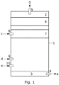
- a feeding device for preparing a feed stream for a solution polymerization comprising a feed vessel, the feed vessel comprising a top zone and a bottom zone; a feed outlet for withdrawing the feed stream, wherein the feed outlet is positioned at the bottom zone; a waste outlet for withdrawing a waste vapour stream, wherein the waste outlet is positioned at the top zone; a first heat exchanger positioned below the top zone; an absorber positioned below the first heat exchanger; a first inlet for introducing a fresh liquid stream into or on top of the absorber, wherein the first inlet is positioned at the absorber; a second inlet for introducing a recycle liquid stream, wherein the second inlet is positioned below the first inlet; and a third inlet for introducing a recycle vapour stream, wherein the third inlet is positioned below the second inlet and above the feed outlet.
- freshness liquid' denotes a liquid used in the feed stream having no amounts of volatile components at ambient conditions, i.e. 1 atm pressure and 20 °C.
- 'recycle liquid' denotes a liquid used in the feed stream having an amount of volatile components at ambient conditions, i.e. 1 atm pressure and 20 °C.
- 'recycle vapour' denotes a gaseous composition comprising an amount of volatile components.
- the heat exchanger is part of the feed vessel (1), such a setup is not necessarily needed.
- the first heat exchanger (6) could be positioned outside of the feed vessel (1) and be respectively connected to the vessel to receive the waste vapour stream (b) and to return the condensed waste vapour stream into the feed vessel (1).
- the feeding device of the present invention further comprises a second heat exchanger (not shown in the Figures).
- This second heat exchanger is positioned at the fresh liquid stream (c) upstream to the first inlet (8) with respect to the flow direction of the fresh liquid stream (c).
- This heat exchanger can be used to cool down the fresh liquid stream (c) before entering the absorber (7) to support that less volatile reactants are taken with the waste vapour stream (b) and vented off.
- the second inlet (9) further comprises a sprayer device configured to spray the recycle liquid stream (d) into the feed vessel (1).
- the effect of the spraying by the spraying device is that a gaseous/liquid phase system with a very high phase separating surface is formed in a short period of time, whereby the liquid part of the system is the recycle liquid stream (d).
- volatile components comprised in the liquid recycle stream are set free and travel towards the top zone (2) of the feed vessel (1).
- the condensed part of the recycle liquid stream is finely dispersed and travels down towards the bottom zone (3) of the feed vessel (1).
- the fine dispersion makes the liquid more absorptive in view of volatile components comprised in the recycle vapour stream (e) travelling counter currently up from the third inlet (10) to the top zone (2) of the feed vessel (1).
- the feeding device of the present invention further comprises a third inlet (10) for introducing the recycle vapour stream (e) positioned below the second inlet (9) and above the feed outlet (4).
- a third inlet (10) for introducing the recycle vapour stream (e) positioned below the second inlet (9) and above the feed outlet (4).
- the volatile components of the recycle vapour stream (e) travel upwards to the top zone (2) thereby passing and contacting the liquid components of the fresh liquid stream (c) and the recycle liquid stream (d). This allows selective solving of reactants from the recycle vapour stream (e) and reintroduction into the feed stream (a).
- the third inlet (10) is positioned at the bottom zone (3) and comprises a dosing pipe (13) extending into the bottom zone (3) of the feed vessel (1).
- a dosing pipe can be a distribution pipe, preferably having a length of the diameter of the feeding vessel (1), with holes therein.
- the bottom zone (3) is configured to hold the liquid phase of the feed stream (a). This is indicated in the Figures by the waved line.
- the dosing pipe is configured to extend within the liquid phase of the feed stream (a).
- the recycle vapour stream (e) passing the dosing pipe is not only finely dispersed and disturbed, but also is forced to travel through the liquid in the bottom zone.
- This has the effect that volatile components, which are most easily solvable in the liquid, such as reactants, are dissolved in the feed stream liquid in the first place due to the significantly enhanced liquid/gas surface area.
- this embodiment has the advantage that the recycle vapour stream (e) is disturbed and, hence, the contacting with the recycle liquid stream (d) is also improved.
- the advantage of contacting the recycle vapour stream (e) with the recycle liquid stream (d) is that reactants in the recycle vapour stream (e) might already be solved in the recycle liquid stream (d).
- the feeding device of the present invention furthermore comprises a feed stream storage vessel configured to store the feed stream (a) positioned downstream of the feed outlet (4).
- the storage vessel has the advantage that it can be ensured that the feed stream (a) is not running empty and the polymerization reactor is constantly and reliably supplemented with feed stream.
- the feeding device of the present invention comprises further means for preparing the feed stream (a).
- the feed stream (a) might have to be enriched in certain reactants and also hydrogen, where necessary.
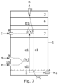
- the conditions of the stream might have to be adjusted before entering the polymerization reactor. Therefore, as depicted in Figure 6 , the feeding device of the present invention preferably further comprises a pump (15) positioned downstream of the feed outlet (4) of the feed vessel (1) with reference to the flow direction of the feed stream (a).
- a pump ensures that the pressure of the feed stream can be adjusted to the pressure the polymerization reactor (16; not part of the feeding device) is operated at.
- the feeding device of the present invention further comprises at least one third heat exchanger (18) positioned downstream of the feed outlet (4) with reference to the flow direction of the feed stream (a).
- the pump (15) is positioned upstream of the at least one third heat exchanger (18) with reference to the flow direction of the feed stream (a).
- the feeding process of the present invention is connected to a solution polymerization process.
- the feeding process provides the feed stream for a solution polymerization process.
- the feeding process is used to recycle streams (liquid and also vapour streams) withdrawn from a solution polymerization process.
- these two solution polymerization processes i.e. the one the feed stream is fed to and the one the recycle streams are taken from
- these two solution polymerization processes are one identical solution polymerization process. Therefore, the solution polymerization process should be described in the following.
- the feed stream can be further modified by introducing at least one monomer into the feed stream (a), introducing at least one comonomer into the feed stream (a) and/or introducing hydrogen into the feed stream (a).
- the process is carried out in the range of 3 to 8 barg pressure.
Landscapes
- Chemical & Material Sciences (AREA)
- Chemical Kinetics & Catalysis (AREA)
- Organic Chemistry (AREA)
- Health & Medical Sciences (AREA)
- Medicinal Chemistry (AREA)
- Polymers & Plastics (AREA)
- Engineering & Computer Science (AREA)
- Dispersion Chemistry (AREA)
- Combustion & Propulsion (AREA)
- Analytical Chemistry (AREA)
- General Chemical & Material Sciences (AREA)
- Oil, Petroleum & Natural Gas (AREA)
- Polymerisation Methods In General (AREA)
- Organic Low-Molecular-Weight Compounds And Preparation Thereof (AREA)
- Other Resins Obtained By Reactions Not Involving Carbon-To-Carbon Unsaturated Bonds (AREA)
- Feeding, Discharge, Calcimining, Fusing, And Gas-Generation Devices (AREA)
- Physical Or Chemical Processes And Apparatus (AREA)
Claims (15)
- Zuführvorrichtung für das Vorbereiten eines Zufuhrstroms (a) für eine Lösungspolymerisation, die ein Zufuhrgefäß (1) umfasst, wobei das Zufuhrgefäß (1) umfasst:- eine obere Zone (2) und eine untere Zone (3),- einen Zufuhrstromauslass als einen Zufuhrauslass (4), der konfiguriert ist zum Ausführen des Zufuhrstroms (a), wobei der Zufuhrstromauslass (4) an der unteren Zone (3) angeordnet ist,- einen Abdampfstromauslass als einen Ablassauslass (5), der konfiguriert ist zum Ausführen eines Abdampfstroms (b), wobei der Ablassauslass (5) an der oberen Zone (2) angeordnet ist,- einen ersten Wärmetauscher (6), der unter der oberen Zone (2) angeordnet ist,- einen Absorbierer (7), der unter dem ersten Wärmetauscher (6) angeordnet ist,- einen Frischflüssigkeitsstromeinlass als einen ersten Einlass (8), der konfiguriert ist zum Einführen eines Frischflüssigkeitsstroms (c) in oder über dem Absorbierer (7), wobei der erste Einlass (8) an dem Absorbierer (7) angeordnet ist,- einen Rückführflüssigkeitsstromeinlass als einen zweiten Einlass (9), der konfiguriert ist zum Einführen eines Rückführflüssigkeitsstroms (d), wobei der zweite Einlass (9) unter dem ersten Einlass (8) angeordnet ist, und- einen Rückführdampfstromeinlass als einen dritten Einlass (10), der konfiguriert ist zum Einführen eines Rückführdampfstroms (e), wobei der dritte Einlass (10) unter dem zweiten Einlass (9) und über dem Zufuhrauslass (4) angeordnet ist.
- Zuführvorrichtung nach Anspruch 1, die weiterhin umfasst:- ein Zufuhrstrom-Speichergefäß, das konfiguriert ist zum Speichern des Zufuhrstroms (a) und stromabwärts von dem Zufuhrauslass (4) angeordnet ist.
- Zuführvorrichtung nach einem der vorstehenden Ansprüche, wobei der zweite Einlass (9) weiterhin eine Sprüheinrichtung umfasst, die konfiguriert ist zum Sprühen des wenigstens einen Rückführflüssigkeitsstroms (d) in das Zuführgefäß (1).
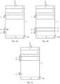
- Zuführvorrichtung nach einem der vorstehenden Ansprüche, wobei das Zuführgefäß (1) weiterhin einen ersten Verteiler (11), der über dem zweiten Einlass (9) angeordnet ist, und einen zweiten Verteiler (12), der unter dem zweiten Einlass (9) angeordnet ist, umfasst.
- Zuführvorrichtung nach Anspruch 1 oder 2, wobei der zweite Einlass (9) an dem Absorbierer (7) angeordnet ist.
- Zuführvorrichtung nach einem der vorstehenden Ansprüche, wobei der dritte Einlass (10) in der unteren Zone (3) angeordnet ist und wobei der dritte Einlass (10) weiterhin ein sich in die untere Zone (3) erstreckendes Dosierungsrohr (13) umfasst.
- Zuführvorrichtung nach einem der vorstehenden Ansprüche, wobei das Zufuhrgefäß (1) weiterhin einen dritten Verteiler (14), der über dem dritten Einlass (10) angeordnet ist, umfasst.
- Lösungspolymerisationsreaktoranordnung, die eine Zuführvorrichtung gemäß einem der vorstehenden Ansprüche umfasst.
- Verfahren zum Vorbereiten eines Zufuhrstroms (a) für eine Lösungspolymerisation in einem Zufuhrgefäß (1), wobei der Zufuhrstrom (a) wenigstens ein Lösungsmittel, wenigstens ein Reaktionsmittel und optional Wasserstoff umfasst, wobei das Verfahren die folgenden Schritte umfasst:(i) Vorsehen wenigstens eines Frischflüssigkeitsstroms (c), der das wenigstens eine Lösungsmittel und optional das wenigstens eine Reaktionsmittel umfasst,(ii) Vorsehen wenigstens eines Rückführflüssigkeitsstroms (d), der das wenigstens eine Lösungsmittel und das wenigstens eine Reaktionsmittel umfasst,(iii) Vorsehen wenigstens eines Rückführdampfstroms (e), der das wenigstens eine Reaktionsmittel umfasst,(iv) Kontaktieren des wenigstens einen Rückführdampfstroms (e) mit dem wenigstens einen Rückführflüssigkeitsstrom (d), was einen kontaktierten Rückführflüssigkeitsstrom (d1) und einen kontaktierten Rückführdampfstrom (e1) ergibt,(v) Kontaktieren des kontaktierten Rückführdampfstroms (e1) mit dem wenigstens einen Frischflüssigkeitsstrom (c), was einen kontaktierten Frischflüssigkeitsstrom (c1) und einen Abdampfstrom (b) ergibt,(vi) Kombinieren des kontaktierten Frischflüssigkeitsstroms (c1) mit dem kontaktierten Rückführflüssigkeitsstrom (d1), was den Zufuhrstrom (a) ergibt,(vii) Ausführen des Abdampfstroms (b) über einen Ablassauslass (5), der an einer oberen Zone (2) des Zufuhrgefäßes (1) angeordnet ist,(viii) Ausführen des Zufuhrstroms (a) über einen Zufuhrauslass (4), der an einer unteren Zone (3) des Zufuhrgefäßes (1) angeordnet ist, wobei:in dem Schritt (i) der wenigstens eine Frischflüssigkeitsstrom (c) über einen ersten Einlass (8) in oder über einem Absorbierer (7) vorgesehen wird, wobei der erste Einlass (8) an dem Absorbierer (7) angeordnet ist,in dem Schritt (ii) der wenigstens eine Rückführflüssigkeitsstrom (d) über einen zweiten Einlass (9) vorgesehen wird, wobei der zweite Einlass (9) unter dem ersten Einlass (8) angeordnet ist,in dem Schritt (iii) der wenigstens eine Rückführdampfstrom (e) über einen dritten Einlass (10) vorgesehen wird, wobei der dritte Einlass (10) unter dem zweiten Einlass (9) und über dem Zufuhrauslass (4) angeordnet ist.
- Verfahren nach Anspruch 9, wobei der Schritt (vi) in dem Schritt (v) ausgeführt wird, sodass der kontaktierte Frischflüssigkeitsstrom (c1) auch mit dem Rückführdampfstrom (e) kontaktiert wird.
- Verfahren nach Anspruch 9 oder 10, das weiterhin den folgenden Schritt umfasst:
(ix) Verteilen des Rückführflüssigkeitsstroms (d) vor dem Schritt (iv). - Verfahren nach einem der Ansprüche 9 bis 11, das weiterhin den folgenden Schritt umfasst:
(x) Verteilen des Rückführdampfstroms (e) vor dem Schritt (iv). - Verfahren nach einem der Ansprüche 9 bis 12, das weiterhin den folgenden Schritt umfasst:
(xi) unmittelbares Speichern des Zufuhrstroms (a) in einem Speichergefäß nach dem Schritt (viii). - Verfahren nach einem der Ansprüche 9 bis 13, das weiterhin den folgenden Schritt umfasst:
(xii) wenigstens teilweises Kondensieren des Abdampfstroms (b) unter Verwendung eines ersten Wärmetauschers (6), was einen kondensierten Abdampfstrom (b1) ergibt, und Wiedereinführen des kondensierten Abdampfstroms (b1) in dem Schritt (v). - Verfahren nach einem der Ansprüche 9 bis 14, das weiterhin den folgenden Schritt umfasst:
(xiii) wenigstens teilweises Kühlen des Frischflüssigkeitsstroms (c) unter Verwendung eines zweiten Wärmetauschers vor dem Schritt (i).
Priority Applications (9)
| Application Number | Priority Date | Filing Date | Title |
|---|---|---|---|
| PL20208837.3T PL4000723T3 (pl) | 2020-11-20 | 2020-11-20 | Urządzenie i sposób przygotowania strumienia zasilającego do polimeryzacji w roztworze |
| EP20208837.3A EP4000723B1 (de) | 2020-11-20 | 2020-11-20 | Vorrichtung und verfahren zur herstellung eines zulaufstroms zur lösungspolymerisierung |
| ES20208837T ES3037453T3 (en) | 2020-11-20 | 2020-11-20 | Device and process for preparing a feed stream for solution polymerization |
| TW110139053A TW202231347A (zh) | 2020-11-20 | 2021-10-21 | 用於製備用於溶液聚合的進料流的裝置和方法 |
| PCT/EP2021/081291 WO2022106284A1 (en) | 2020-11-20 | 2021-11-10 | Device and process for preparing a feed stream for solution polymerization |
| KR1020237014453A KR102918815B1 (ko) | 2020-11-20 | 2021-11-10 | 용액 중합을 위한 공급 스트림을 제조하기 위한 장치 및 프로세스 |
| CN202180078097.6A CN116472104A (zh) | 2020-11-20 | 2021-11-10 | 用于制备溶液聚合的进料流的装置和方法 |
| CA3202381A CA3202381C (en) | 2020-11-20 | 2021-11-10 | Device and process for preparing a feed stream for solution polymerization |
| US18/036,742 US20230415113A1 (en) | 2020-11-20 | 2021-11-10 | Device and process for preparing a feed stream for solution polymerization |
Applications Claiming Priority (1)
| Application Number | Priority Date | Filing Date | Title |
|---|---|---|---|
| EP20208837.3A EP4000723B1 (de) | 2020-11-20 | 2020-11-20 | Vorrichtung und verfahren zur herstellung eines zulaufstroms zur lösungspolymerisierung |
Publications (3)
| Publication Number | Publication Date |
|---|---|
| EP4000723A1 EP4000723A1 (de) | 2022-05-25 |
| EP4000723C0 EP4000723C0 (de) | 2025-07-09 |
| EP4000723B1 true EP4000723B1 (de) | 2025-07-09 |
Family
ID=73598667
Family Applications (1)
| Application Number | Title | Priority Date | Filing Date |
|---|---|---|---|
| EP20208837.3A Active EP4000723B1 (de) | 2020-11-20 | 2020-11-20 | Vorrichtung und verfahren zur herstellung eines zulaufstroms zur lösungspolymerisierung |
Country Status (8)
| Country | Link |
|---|---|
| US (1) | US20230415113A1 (de) |
| EP (1) | EP4000723B1 (de) |
| KR (1) | KR102918815B1 (de) |
| CN (1) | CN116472104A (de) |
| ES (1) | ES3037453T3 (de) |
| PL (1) | PL4000723T3 (de) |
| TW (1) | TW202231347A (de) |
| WO (1) | WO2022106284A1 (de) |
Families Citing this family (4)
| Publication number | Priority date | Publication date | Assignee | Title |
|---|---|---|---|---|
| EP4537919A1 (de) * | 2020-08-13 | 2025-04-16 | Borealis AG | Verfahren zum sieben von polymer aus einem abgasstrom bei reduzierten niveaus von polymermitnahme |
| EP4406983A1 (de) | 2023-01-24 | 2024-07-31 | Borealis AG | Verfahren zur herstellung eines alpha-olefin-zustroms und polymerisationsverfahren damit |
| EP4721850A1 (de) | 2024-10-02 | 2026-04-08 | Borealis GmbH | System und verfahren zur herstellung eines zufuhrstroms für ein lösungspolymerisierungsverfahren |
| EP4721849A1 (de) | 2024-10-02 | 2026-04-08 | Borealis GmbH | Vorrichtung und verfahren zur herstellung eines einsatzstroms für die lösungspolymerisierung |
Family Cites Families (17)
| Publication number | Priority date | Publication date | Assignee | Title |
|---|---|---|---|---|
| IL80888A (en) | 1985-12-12 | 1991-12-12 | Exxon Chemical Patents Inc | Olefin polymerization catalysts,their preparation and use thereof |
| NL8700321A (nl) | 1987-02-11 | 1988-09-01 | Stamicarbon | Katalysatorsysteem voor hoge temperatuur (co)polymerisatie van etheen. |
| NL8700322A (nl) | 1987-02-11 | 1988-09-01 | Stamicarbon | Katalysatorsysteem voor (co)polymerisatie van etheen in solutie. |
| NL8700558A (nl) | 1987-03-09 | 1988-10-03 | Stamicarbon | Katalysatorsysteem voor hoge temperatuur (co)polymerisatie van etheen. |
| US5001205A (en) | 1988-06-16 | 1991-03-19 | Exxon Chemical Patents Inc. | Process for production of a high molecular weight ethylene α-olefin elastomer with a metallocene alumoxane catalyst |
| US5001244A (en) | 1988-06-22 | 1991-03-19 | Exxon Chemical Patents Inc. | Metallocene, hydrocarbylaluminum and hydrocarbylboroxine olefin polymerization catalyst |
| CA2117888C (en) | 1992-06-15 | 2001-05-15 | Howard William Turner | High temperature polymerization process using ionic catalysts to produce polyolefins |
| US5681908A (en) * | 1995-03-03 | 1997-10-28 | Advanced Extraction Technologies, Inc. | Absorption process for rejection of reactor byproducts and recovery of monomers from waste gas streams in olefin polymerization processes |
| DE10037774A1 (de) * | 2000-08-03 | 2002-02-14 | Bayer Ag | Verfahren und Vorrichtung zur Gewinnung organischer Substanzen aus einem diese Substanzen enthaltenden Gasgemisch |
| EP2219756B1 (de) * | 2007-11-27 | 2017-03-15 | Univation Technologies, LLC | Verfahren zur verwendung eines integrierten kohlenwasserstoffstromstrippers |
| WO2011011427A1 (en) * | 2009-07-23 | 2011-01-27 | Univation Technologies, Llc | Polymerization reaction system |
| US8410329B2 (en) * | 2010-10-15 | 2013-04-02 | Chevron Phillips Chemical Company Lp | Ethylene separation |
| EP2848635A1 (de) * | 2013-09-16 | 2015-03-18 | Ineos Europe AG | Polymerisationsverfahren |
| EP3074433B1 (de) * | 2013-11-29 | 2018-05-23 | Saudi Basic Industries Corporation | Verfahren zur kontinuierlichen polymerisation von olefinmonomeren in einem reaktor |
| US10759883B2 (en) * | 2015-08-07 | 2020-09-01 | Sabin Global Technologies B.V. | Process for the polymerization of olefins |
| CN108602904B (zh) * | 2015-12-15 | 2021-03-12 | Sabic环球技术有限责任公司 | 烯烃聚合方法 |
| SG11202007631PA (en) * | 2018-02-22 | 2020-09-29 | Borealis Ag | Process |
-
2020
- 2020-11-20 EP EP20208837.3A patent/EP4000723B1/de active Active
- 2020-11-20 PL PL20208837.3T patent/PL4000723T3/pl unknown
- 2020-11-20 ES ES20208837T patent/ES3037453T3/es active Active
-
2021
- 2021-10-21 TW TW110139053A patent/TW202231347A/zh unknown
- 2021-11-10 KR KR1020237014453A patent/KR102918815B1/ko active Active
- 2021-11-10 CN CN202180078097.6A patent/CN116472104A/zh active Pending
- 2021-11-10 WO PCT/EP2021/081291 patent/WO2022106284A1/en not_active Ceased
- 2021-11-10 US US18/036,742 patent/US20230415113A1/en active Pending
Also Published As
| Publication number | Publication date |
|---|---|
| TW202231347A (zh) | 2022-08-16 |
| CN116472104A (zh) | 2023-07-21 |
| KR102918815B1 (ko) | 2026-01-27 |
| WO2022106284A1 (en) | 2022-05-27 |
| US20230415113A1 (en) | 2023-12-28 |
| KR20230078757A (ko) | 2023-06-02 |
| EP4000723C0 (de) | 2025-07-09 |
| EP4000723A1 (de) | 2022-05-25 |
| CA3202381A1 (en) | 2022-05-27 |
| ES3037453T3 (en) | 2025-10-02 |
| PL4000723T3 (pl) | 2025-10-06 |
Similar Documents
| Publication | Publication Date | Title |
|---|---|---|
| EP4000723B1 (de) | Vorrichtung und verfahren zur herstellung eines zulaufstroms zur lösungspolymerisierung | |
| KR102051243B1 (ko) | 고분자의 인-라인 혼합을 위한 공정 및 기기 | |
| CA3079922C (en) | A method of recovering olefins in a solution polymerisation process | |
| US12194398B2 (en) | Screening assembly and process for screening polymer from an effluent stream at reduced levels of polymer entrainment | |
| CN111295397B (zh) | 一种在溶液聚合过程中回收烯烃的方法 | |
| US20240384011A1 (en) | Process for Producing a Polyolefin with Low Volatile Content | |
| CA3202381C (en) | Device and process for preparing a feed stream for solution polymerization | |
| US20240002552A1 (en) | Polymerization Process and Arrangement | |
| WO2019099134A1 (en) | Gas-phase olefin polymerization process | |
| EP4721849A1 (de) | Vorrichtung und verfahren zur herstellung eines einsatzstroms für die lösungspolymerisierung | |
| WO2002040146A1 (en) | Fluidised bed reactor | |
| BR112021010884A2 (pt) | Sistema para polimerização em solução, e, método | |
| EP3997135B1 (de) | Polymerisierungsverfahren | |
| US12599883B2 (en) | Screening assembly and process for screening polymer from an effluent stream at reduced levels of polymer entrainment | |
| CA3191185C (en) | Screening assembly and process for screening polymer from an effluent stream at reduced levels of polymer entrainment |
Legal Events
| Date | Code | Title | Description |
|---|---|---|---|
| PUAI | Public reference made under article 153(3) epc to a published international application that has entered the european phase |
Free format text: ORIGINAL CODE: 0009012 |
|
| STAA | Information on the status of an ep patent application or granted ep patent |
Free format text: STATUS: THE APPLICATION HAS BEEN PUBLISHED |
|
| AK | Designated contracting states |
Kind code of ref document: A1 Designated state(s): AL AT BE BG CH CY CZ DE DK EE ES FI FR GB GR HR HU IE IS IT LI LT LU LV MC MK MT NL NO PL PT RO RS SE SI SK SM TR |
|
| STAA | Information on the status of an ep patent application or granted ep patent |
Free format text: STATUS: REQUEST FOR EXAMINATION WAS MADE |
|
| 17P | Request for examination filed |
Effective date: 20220722 |
|
| RBV | Designated contracting states (corrected) |
Designated state(s): AL AT BE BG CH CY CZ DE DK EE ES FI FR GB GR HR HU IE IS IT LI LT LU LV MC MK MT NL NO PL PT RO RS SE SI SK SM TR |
|
| STAA | Information on the status of an ep patent application or granted ep patent |
Free format text: STATUS: EXAMINATION IS IN PROGRESS |
|
| 17Q | First examination report despatched |
Effective date: 20250129 |
|
| GRAP | Despatch of communication of intention to grant a patent |
Free format text: ORIGINAL CODE: EPIDOSNIGR1 |
|
| STAA | Information on the status of an ep patent application or granted ep patent |
Free format text: STATUS: GRANT OF PATENT IS INTENDED |
|
| INTG | Intention to grant announced |
Effective date: 20250408 |
|
| GRAS | Grant fee paid |
Free format text: ORIGINAL CODE: EPIDOSNIGR3 |
|
| GRAA | (expected) grant |
Free format text: ORIGINAL CODE: 0009210 |
|
| STAA | Information on the status of an ep patent application or granted ep patent |
Free format text: STATUS: THE PATENT HAS BEEN GRANTED |
|
| REG | Reference to a national code |
Ref country code: DE Ref legal event code: R081 Ref document number: 602020054133 Country of ref document: DE Owner name: BOREALIS GMBH, AT Free format text: FORMER OWNER: BOREALIS AG, VIENNA, AT |
|
| AK | Designated contracting states |
Kind code of ref document: B1 Designated state(s): AL AT BE BG CH CY CZ DE DK EE ES FI FR GB GR HR HU IE IS IT LI LT LU LV MC MK MT NL NO PL PT RO RS SE SI SK SM TR |
|
| REG | Reference to a national code |
Ref country code: GB Ref legal event code: FG4D |
|
| REG | Reference to a national code |
Ref country code: CH Ref legal event code: EP |
|
| RAP4 | Party data changed (patent owner data changed or rights of a patent transferred) |
Owner name: BOREALIS GMBH |
|
| REG | Reference to a national code |
Ref country code: IE Ref legal event code: FG4D |
|
| REG | Reference to a national code |
Ref country code: DE Ref legal event code: R096 Ref document number: 602020054133 Country of ref document: DE |
|
| U01 | Request for unitary effect filed |
Effective date: 20250709 |
|
| U07 | Unitary effect registered |
Designated state(s): AT BE BG DE DK EE FI FR IT LT LU LV MT NL PT RO SE SI Effective date: 20250715 |
|
| REG | Reference to a national code |
Ref country code: ES Ref legal event code: FG2A Ref document number: 3037453 Country of ref document: ES Kind code of ref document: T3 Effective date: 20251002 |
|
| U20 | Renewal fee for the european patent with unitary effect paid |
Year of fee payment: 6 Effective date: 20251127 |
|
| PG25 | Lapsed in a contracting state [announced via postgrant information from national office to epo] |
Ref country code: IS Free format text: LAPSE BECAUSE OF FAILURE TO SUBMIT A TRANSLATION OF THE DESCRIPTION OR TO PAY THE FEE WITHIN THE PRESCRIBED TIME-LIMIT Effective date: 20251109 |
|
| PG25 | Lapsed in a contracting state [announced via postgrant information from national office to epo] |
Ref country code: NO Free format text: LAPSE BECAUSE OF FAILURE TO SUBMIT A TRANSLATION OF THE DESCRIPTION OR TO PAY THE FEE WITHIN THE PRESCRIBED TIME-LIMIT Effective date: 20251009 |
|
| PG25 | Lapsed in a contracting state [announced via postgrant information from national office to epo] |
Ref country code: HR Free format text: LAPSE BECAUSE OF FAILURE TO SUBMIT A TRANSLATION OF THE DESCRIPTION OR TO PAY THE FEE WITHIN THE PRESCRIBED TIME-LIMIT Effective date: 20250709 |
|
| PG25 | Lapsed in a contracting state [announced via postgrant information from national office to epo] |
Ref country code: GR Free format text: LAPSE BECAUSE OF FAILURE TO SUBMIT A TRANSLATION OF THE DESCRIPTION OR TO PAY THE FEE WITHIN THE PRESCRIBED TIME-LIMIT Effective date: 20251010 |
|
| PGFP | Annual fee paid to national office [announced via postgrant information from national office to epo] |
Ref country code: PL Payment date: 20251106 Year of fee payment: 6 |
|
| PG25 | Lapsed in a contracting state [announced via postgrant information from national office to epo] |
Ref country code: RS Free format text: LAPSE BECAUSE OF FAILURE TO SUBMIT A TRANSLATION OF THE DESCRIPTION OR TO PAY THE FEE WITHIN THE PRESCRIBED TIME-LIMIT Effective date: 20251009 |
|
| PGFP | Annual fee paid to national office [announced via postgrant information from national office to epo] |
Ref country code: ES Payment date: 20251229 Year of fee payment: 6 |
|
| PG25 | Lapsed in a contracting state [announced via postgrant information from national office to epo] |
Ref country code: SM Free format text: LAPSE BECAUSE OF FAILURE TO SUBMIT A TRANSLATION OF THE DESCRIPTION OR TO PAY THE FEE WITHIN THE PRESCRIBED TIME-LIMIT Effective date: 20250709 |