EP4000737B1 - Elektrostatisches staubentfernungsgerät - Google Patents
Elektrostatisches staubentfernungsgerät Download PDFInfo
- Publication number
- EP4000737B1 EP4000737B1 EP20854082.3A EP20854082A EP4000737B1 EP 4000737 B1 EP4000737 B1 EP 4000737B1 EP 20854082 A EP20854082 A EP 20854082A EP 4000737 B1 EP4000737 B1 EP 4000737B1
- Authority
- EP
- European Patent Office
- Prior art keywords
- potential
- units
- low
- positioning
- frame
- Prior art date
- Legal status (The legal status is an assumption and is not a legal conclusion. Google has not performed a legal analysis and makes no representation as to the accuracy of the status listed.)
- Active
Links
Images



Classifications
-
- B—PERFORMING OPERATIONS; TRANSPORTING
- B03—SEPARATION OF SOLID MATERIALS USING LIQUIDS OR USING PNEUMATIC TABLES OR JIGS; MAGNETIC OR ELECTROSTATIC SEPARATION OF SOLID MATERIALS FROM SOLID MATERIALS OR FLUIDS; SEPARATION BY HIGH-VOLTAGE ELECTRIC FIELDS
- B03C—MAGNETIC OR ELECTROSTATIC SEPARATION OF SOLID MATERIALS FROM SOLID MATERIALS OR FLUIDS; SEPARATION BY HIGH-VOLTAGE ELECTRIC FIELDS
- B03C3/00—Separating dispersed particles from gases or vapour, e.g. air, by electrostatic effect
- B03C3/34—Constructional details or accessories or operation thereof
- B03C3/66—Applications of electricity supply techniques
- B03C3/70—Applications of electricity supply techniques insulating in electric separators
-
- B—PERFORMING OPERATIONS; TRANSPORTING
- B03—SEPARATION OF SOLID MATERIALS USING LIQUIDS OR USING PNEUMATIC TABLES OR JIGS; MAGNETIC OR ELECTROSTATIC SEPARATION OF SOLID MATERIALS FROM SOLID MATERIALS OR FLUIDS; SEPARATION BY HIGH-VOLTAGE ELECTRIC FIELDS
- B03C—MAGNETIC OR ELECTROSTATIC SEPARATION OF SOLID MATERIALS FROM SOLID MATERIALS OR FLUIDS; SEPARATION BY HIGH-VOLTAGE ELECTRIC FIELDS
- B03C3/00—Separating dispersed particles from gases or vapour, e.g. air, by electrostatic effect
- B03C3/34—Constructional details or accessories or operation thereof
- B03C3/40—Electrode constructions
- B03C3/60—Use of special materials other than liquids
- B03C3/64—Use of special materials other than liquids synthetic resins
-
- B—PERFORMING OPERATIONS; TRANSPORTING
- B03—SEPARATION OF SOLID MATERIALS USING LIQUIDS OR USING PNEUMATIC TABLES OR JIGS; MAGNETIC OR ELECTROSTATIC SEPARATION OF SOLID MATERIALS FROM SOLID MATERIALS OR FLUIDS; SEPARATION BY HIGH-VOLTAGE ELECTRIC FIELDS
- B03C—MAGNETIC OR ELECTROSTATIC SEPARATION OF SOLID MATERIALS FROM SOLID MATERIALS OR FLUIDS; SEPARATION BY HIGH-VOLTAGE ELECTRIC FIELDS
- B03C3/00—Separating dispersed particles from gases or vapour, e.g. air, by electrostatic effect
- B03C3/02—Plant or installations having external electricity supply
- B03C3/04—Plant or installations having external electricity supply dry type
-
- B—PERFORMING OPERATIONS; TRANSPORTING
- B03—SEPARATION OF SOLID MATERIALS USING LIQUIDS OR USING PNEUMATIC TABLES OR JIGS; MAGNETIC OR ELECTROSTATIC SEPARATION OF SOLID MATERIALS FROM SOLID MATERIALS OR FLUIDS; SEPARATION BY HIGH-VOLTAGE ELECTRIC FIELDS
- B03C—MAGNETIC OR ELECTROSTATIC SEPARATION OF SOLID MATERIALS FROM SOLID MATERIALS OR FLUIDS; SEPARATION BY HIGH-VOLTAGE ELECTRIC FIELDS
- B03C3/00—Separating dispersed particles from gases or vapour, e.g. air, by electrostatic effect
- B03C3/02—Plant or installations having external electricity supply
- B03C3/04—Plant or installations having external electricity supply dry type
- B03C3/08—Plant or installations having external electricity supply dry type characterised by presence of stationary flat electrodes arranged with their flat surfaces parallel to the gas stream
-
- B—PERFORMING OPERATIONS; TRANSPORTING
- B03—SEPARATION OF SOLID MATERIALS USING LIQUIDS OR USING PNEUMATIC TABLES OR JIGS; MAGNETIC OR ELECTROSTATIC SEPARATION OF SOLID MATERIALS FROM SOLID MATERIALS OR FLUIDS; SEPARATION BY HIGH-VOLTAGE ELECTRIC FIELDS
- B03C—MAGNETIC OR ELECTROSTATIC SEPARATION OF SOLID MATERIALS FROM SOLID MATERIALS OR FLUIDS; SEPARATION BY HIGH-VOLTAGE ELECTRIC FIELDS
- B03C3/00—Separating dispersed particles from gases or vapour, e.g. air, by electrostatic effect
- B03C3/34—Constructional details or accessories or operation thereof
-
- B—PERFORMING OPERATIONS; TRANSPORTING
- B03—SEPARATION OF SOLID MATERIALS USING LIQUIDS OR USING PNEUMATIC TABLES OR JIGS; MAGNETIC OR ELECTROSTATIC SEPARATION OF SOLID MATERIALS FROM SOLID MATERIALS OR FLUIDS; SEPARATION BY HIGH-VOLTAGE ELECTRIC FIELDS
- B03C—MAGNETIC OR ELECTROSTATIC SEPARATION OF SOLID MATERIALS FROM SOLID MATERIALS OR FLUIDS; SEPARATION BY HIGH-VOLTAGE ELECTRIC FIELDS
- B03C3/00—Separating dispersed particles from gases or vapour, e.g. air, by electrostatic effect
- B03C3/34—Constructional details or accessories or operation thereof
- B03C3/40—Electrode constructions
-
- B—PERFORMING OPERATIONS; TRANSPORTING
- B03—SEPARATION OF SOLID MATERIALS USING LIQUIDS OR USING PNEUMATIC TABLES OR JIGS; MAGNETIC OR ELECTROSTATIC SEPARATION OF SOLID MATERIALS FROM SOLID MATERIALS OR FLUIDS; SEPARATION BY HIGH-VOLTAGE ELECTRIC FIELDS
- B03C—MAGNETIC OR ELECTROSTATIC SEPARATION OF SOLID MATERIALS FROM SOLID MATERIALS OR FLUIDS; SEPARATION BY HIGH-VOLTAGE ELECTRIC FIELDS
- B03C3/00—Separating dispersed particles from gases or vapour, e.g. air, by electrostatic effect
- B03C3/34—Constructional details or accessories or operation thereof
- B03C3/40—Electrode constructions
- B03C3/45—Collecting-electrodes
- B03C3/47—Collecting-electrodes flat, e.g. plates, discs, gratings
-
- B—PERFORMING OPERATIONS; TRANSPORTING
- B03—SEPARATION OF SOLID MATERIALS USING LIQUIDS OR USING PNEUMATIC TABLES OR JIGS; MAGNETIC OR ELECTROSTATIC SEPARATION OF SOLID MATERIALS FROM SOLID MATERIALS OR FLUIDS; SEPARATION BY HIGH-VOLTAGE ELECTRIC FIELDS
- B03C—MAGNETIC OR ELECTROSTATIC SEPARATION OF SOLID MATERIALS FROM SOLID MATERIALS OR FLUIDS; SEPARATION BY HIGH-VOLTAGE ELECTRIC FIELDS
- B03C3/00—Separating dispersed particles from gases or vapour, e.g. air, by electrostatic effect
- B03C3/34—Constructional details or accessories or operation thereof
- B03C3/86—Electrode-carrying means
Definitions
- the present disclosure relates to the field of air purification, and more particularly, to an electrostatic dust removal apparatus and an electrode unit thereof.
- Electrostatic dust removal is one of methods for removing dust from one or more gases.
- the principle of the electrostatic dust removal method can be summarized as follows.
- a gas and dust particles entrained in the gas pass through a high-voltage electrostatic field, the gas is electrically separated from the dust particles.
- the dust particles bond with negative ions and are charged negatively.
- the dust particles approach a surface of an anode and are deposited on the surface after discharging. That is, in a strong electric field, an air molecule is ionized into a positive ion and an electron, the electron may encounter the dust particle during approaching the anode, and thus the dust particle is charged negatively so as to be adsorbed onto the anode and then is collected on the anode.
- an electrostatic dust removal apparatus usually uses an electrode made of metal.
- Metal is not only costly, but also difficult to be machined and thus difficult to be processed into various shapes.
- corona discharge is liable to occur between a high-potential electrode and a low-potential electrode which are adjacent to each other, causing production of ozone and occurrence of an electric shock, which affect the use security.
- an additional insulator is provided between the adjacent electrodes, increasing the assembling complexity.
- CN108855621A discloses an electrostatic dust collector.
- the electrostatic dust collector includes a plurality of electrostatic dust collecting sheets arranged and fixed in parallel with each other in order to form a multi-layer structure.
- Conductive layers of the plurality of electrostatic dust collecting sheets are connected to a high-voltage electrode or a ground electrode in an alternate manner to form a structure that the conductive layer of one electrostatic dust collecting sheet is connected to the high-voltage electrode, and the conductive layer of another electrostatic dust collecting sheet is connected to the ground electrode.
- one aim of the present disclosure is to provide an electrostatic dust removal apparatus as defined in claim 1, which has advantages such as lower manufacture cost, easiness to form various structures, high security and convenience for assembly.
- the present disclosure also provides an electrode unit of an electrostatic dust removal apparatus.
- an electrostatic dust removal apparatus including: a frame; and a plurality of electrode units including a plurality of high-potential units and a plurality of low-potential units.
- the plurality of electrode units are provided on the frame and are spaced apart from each other.
- the plurality of high-potential units and the plurality of low-potential units are arranged alternately, and an air channel for removing dust is formed between the electrode units adjacent to each other.
- Each of the plurality of electrode units includes a conducting part and an insulating part, the conducting part is a conductive plastic part and includes an electrical field generator and a conducting end, and the insulating part covers at least a portion of the electrical field generator.
- the plurality of electrode units are arranged along a thickness direction of the plurality of electrode units, and two ends of each of the plurality of electrode units are detachably mounted onto two opposite sides of the frame respectively.
- the electrostatic dust removal apparatus further includes: one high-potential conductor provided at one side of the frame, the high-potential conductor being connected to the conducting end of each of the plurality of high-potential units; and one low-potential conductor provided at another side of the frame that is opposite to the one side, the low-potential conductor being connected to the conducting end of each of the plurality of low-potential units.
- the electrostatic dust removal apparatus has advantages such as lower manufacture cost, easiness to form various structures, high security and convenience for assembly.
- the electrostatic dust removal apparatus may further include one or more of the following additional technical features.
- the insulating part covers the whole electrical field generator; or the electrical field generators adjacent to each other have surfaces facing each other, one of the surfaces is covered by the insulating part, and the other of the surfaces is exposed from the insulating part.
- the conducting part and the insulating part of each of the plurality of electrode units are formed integrally by injection molding.
- one of the electrode units adjacent to each other is provided with a positioning ring, and the other of the electrode units adjacent to each other is provided with a positioning protrusion configured to be inserted into the positioning ring.
- an end positioning structure is provided on the frame, and the positioning ring or the positioning protrusion of the outermost electrode unit fits to the end positioning structure.
- one end of the high-potential unit is the conducting end formed by the conducting part of the high-potential unit
- the other end of the high-potential unit is the insulating end formed by the insulating part of the high-potential unit.
- One end of the low-potential unit is the conducting end formed by the conducting part of the low-potential unit
- the other end of the low-potential unit is an insulating end formed by the insulating part of the low-potential unit.
- the conducting ends of the plurality of high-potential units and the insulating ends of the plurality of low-potential units face the one side of the frame, and the insulating ends of the plurality of high-potential units and the conducting ends of the plurality of low-potential units face the other side of the frame that is opposite to the one side.
- the high-potential conductor is connected to the insulating end of each of the plurality of low-potential units; and the low-potential conductor is connected to the insulating end of each of the plurality of high-potential units.
- the electrostatic dust removal apparatus further includes: a first positioning element, the high-potential conductor being provided on the first positioning element, and the first positioning element fitting to the conducting end of each of the plurality of high-potential units and the insulating end of each of the plurality of low-potential units; and a second positioning element, the low-potential conductor being provided on the second positioning element, and the second positioning element fitting to the conducting end of each of the plurality of low-potential units and the insulating end of each of the plurality of high-potential units.
- the first positioning element is provided with a plurality of first positioning teeth, each of a plurality of first tooth spaces is formed between the first positioning teeth adjacent to each other, the high-potential conductor extends through the first positioning element and is exposed from the plurality of first tooth spaces, and each of the plurality of first positioning teeth is fitted between the conducting end of one high-potential unit and the insulating end of the low-potential unit adjacent to the one high-potential unit.
- the second positioning element is provided with a plurality of second positioning teeth, each of a plurality of second tooth spaces is formed between the second positioning teeth adjacent to each other, the low-potential conductor extends through the second positioning element and is exposed from the plurality of second tooth spaces, and each of the plurality of second positioning teeth is fitted between the conducting end of one low-potential unit and the insulating end of the high-potential unit adjacent to the one low-potential unit.
- the conducting end of each of the plurality of high-potential units and the insulating end of each of the plurality of low-potential units are provided with a first positioning groove respectively, and the first positioning element is fitted into a plurality of first positioning grooves. Further, the conducting end of each of the plurality of low-potential units and the insulating end of each of the plurality of high-potential units are provided with a second positioning groove respectively, and the second positioning element is fitted into a plurality of second positioning grooves.
- the first positioning element is provided with a plurality of first studs spaced apart from each other along its length direction, and the plurality of first studs are mounted on the frame by a plurality of first screw fasteners respectively.
- the second positioning element is provided with a plurality of second studs spaced apart from each other along its length direction, and the plurality of second studs are mounted on the frame by a plurality of second screw fasteners respectively.
- the frame is provided with a plurality of first ribs which are spaced apart from each other and surround the first positioning element, and is provided with a plurality of second ribs which are spaced apart from each other and surround the second positioning element.
- the frame is configured as a rectangle shape which surrounds the plurality of electrode units.
- each of the plurality of electrode units extends along the width direction of the frame, the plurality of electrode units are provided spaced apart from each other along the length direction of the frame, and two ends of each of the plurality of electrode units are detachably mounted onto two opposite sides of the frame in the width direction respectively.
- the electrostatic dust removal apparatus is bent into an arc shape about an axis, the axis extends along the length direction of the frame and is located at the middle of the frame in the width direction of the frame.
- Electrostatic dust removal apparatus 1 Frame 10; End positioning structure 110; First fixing element 120; First fixing groove 121; Second fixing element 130; Second fixing groove 131; Main frame 150; Bottom frame 140; Position-limiting pin 141; Position-limiting sleeve 151; Male snap 142; Female snap 152; Electrode unit 20; high-potential unit 21; low-potential unit 22; Conducting part 210; Electrical field generator 211; Conducting end 212; Insulating part 220; Positioning protrusion 230; Positioning ring 240; Insulating end 221; High-potential conductor 30; Low-potential conductor 40;First positioning element 50; First positioning tooth 510; First tooth space 520; First stud 530; First rib 550; First linear rib 551; First corner rib 552; First positioning groove 231; Second positioning groove 232;Second positioning element 60; Second positioning tooth 610; Second tooth space 620; Second stud 630; axis L.
- orientational or positional relations such as “center”, “upper”, “lower”, “front”, “rear”, “left”, “right”, “vertical”, “horizontal”, “top”, “bottom”, “inside” and “outside”, are all on the basis of the orientational or positional relations illustrated in the drawings.
- Each of those terms is merely for the convenience and simplification of the description of the present disclosure, does not indicate or imply that the indicated device or component must be in a particular orientation or must be constructed and operated in a particular orientation, and therefore cannot be construed as limiting the present disclosure.
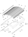
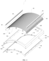
- the electrostatic dust removal apparatus 1 includes a frame 10 and a plurality of electrode units 20.
- the plurality of electrode units 20 are provided on the frame 10 and are spaced apart from each other.
- the plurality of electrode units 20 include at least one high-potential unit 21 and at least one low-potential unit 22, and the at least one high-potential unit 21 and the at least one low-potential unit 22 are arranged alternately. That is, one or more of the plurality of electrode units 20 may be formed as the high-potential unit(s) 21, and one or more of the plurality of electrode units 20 may be formed as the low-potential unit(s) 22.
- the electrode unit 20 adjacent to the high-potential unit 21 is used as the low-potential unit 22
- the electrode unit 20 adjacent to the low-potential unit 22 is used as the high-potential unit 21.
- the plurality of electrode units 20 are arranged in an order of a high-potential unit 21, a low-potential unit 22, a high-potential unit 21, a low-potential unit 22 and so on.
- An air channel for removing dust is formed between the high-potential unit 21 and the low-potential unit 22 which are adjacent to each other.
- the air channel for removing dust extends along a length direction of the high-potential unit 21 and the low-potential unit 22 which are adjacent to each other.
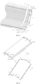
- Each of the plurality of electrode units 20 includes a conducting part 210 and an insulating part 220.
- the conducting part 210 is a conductive plastic part.
- the conducting part 210 includes an electrical field generator 211 and a conducting end 212.
- the electrical field generator 211 refers to a portion of the conducting part 210 that is configured to generate an electrical field
- the conducting end 212 refers to a portion of the conducting part 210 that is configured to realize an electrical connection.
- the insulating part 220 covers at least a portion of the electrical field generator 211.
- the conducting end 212 is exposed from the insulating part 220 for the electrical connection.
- the conducting part 210 of the electrode unit 20 is made from conductive plastic.
- the conductive plastic is easier and more flexible to machine, and can form various structures adapted for different application environments and structural demands of the electrostatic dust removal apparatus 1, and further the cost of the conductive plastic is lower.
- conductive ink is used to form an electrode.
- it requires an additional process to apply the conductive ink, and it is difficult to guarantee the comprehensiveness and uniformity of the application.
- the use of the conductive plastic does not require any additional process, and the stability of the electrical field can be guaranteed.
- At least a portion of the electrical field generator 211 of the conducting part 210 is covered by the insulating part 220, such that electrical field generators 211 adjacent to each other can be separated by at least one layer of insulating material. Therefore, on one hand, the corona discharge between adjacent electrode units 20 can be avoided, so as to reduce the generation of ozone and the risk of electric shock, greatly improving the use security.
- the conducting part 210 and the insulating part 220 can be formed as an integral part, simplifying the assembly. Further, each of the electrode units 20 can be formed as an individual component, facilitating replacement of an individual electrode unit 20 during the process of the manufacture and use.
- the electrode unit 20 can be replaced independently without disposing of the plurality of electrode units 20 or the whole electrostatic dust removal apparatus, thereby indirectly improving the product yield and saving the manufacture cost. Further, during the process of use, an individual electrode unit 20 can be replaced, thereby making the repair and maintain during the process of use more convenient.
- a long and narrow air channel for removing dust can be formed between adjacent electrode units 20, and can extend along the length direction of each of the adjacent electrode units 20. In this way, the wind resistance of the electrostatic dust removal apparatus 1 can be reduced so as to improve the dust removal efficiency.
- the conductive plastic has a tensile strength in the range of 20MPa to 28MPa, an ultimate elongation of not less than 10%, a flexural strength in the range of 32MPa to 40MPa, a flexural modulus in the range of 3000MPa to 3800MPa, and a notched impact strength in the range of 100J/m to 140J/m.
- the conductive plastic has a tensile strength of 24MPa, a flexural strength of 36MPa, a flexural modulus of 3400MPa, and a notched impact strength of 120J/m.
- the conductive plastic has a surface resistivity of 10 3 Ohm-cm, a specific weight in the range of 0.92 g/cm 3 to 1.12 g/cm 3 , flammability in HB class, a shrinkage in the range of 0.4% to 0.8%, and a heat deformation temperature in the range of 95°C to 115°C.
- the conductive plastic has a specific weight of 1.02 g/cm 3 and a heat deformation temperature of 105°C.
- the conductive plastic is subject to a drying process in which drying temperature is in the range of 70°C to 90°C and drying time is in the range of 2 hours to 4 hours.
- drying temperature is 80°C.
- the conductive plastic is subject to an injection molding in which melt temperature is in the range of 180°C to 240°C, front barrel temperature is in the range of 180°C to 240°C, middle barrel temperature is in the range of 180°C to 235°C, rear barrel temperature is in the range of 180°C-230°C, mold temperature is in the range of 50°C to 80°C and injection pressure is in the range of 180°C-240°C.
- the conductive plastic has advantages such as good electrical conduction, good shape retention, light weight and high temperature resistance.
- the electrode unit 20 made from the conductive plastic may have advantages such as lower risk of being damaged and high durability.
- the parameters of properties of the conductive plastic are given in the following table.
- Properties Test Standard (Standard) Test Condition (Condition) Unit Value Mechanical Properties Tensile Strength ASTM D638 10mm/min MPa 24 Ultimate elongation ASTM D638 10mm/min % ⁇ 10 Flexural Strength (Tear strength) ASTM D790 2mm/min MPa 36 Flexural Modulus ASTM D790 2mm/min MPa 3400 IZOD Notched Impact Strength ASTM D256 2.75J J/m 120 Electrical Properties Surface Resistivity ASTM D257 / Ohm-cm 10 3 Others Specific weight ASTM D792 23°C g/cm 3 1.02 Flammability UL94 1.5mm Class HB Shrinkage (Mold Shrinkage) ASTM D955 23°C % 0.4-0.8 Heat Deformation Temperature (HDT) ASTM D1525 1.82MPa °C 105 Drying Process (Materials Drying Process) Drying Temperature °C 80 Drying Time Hour 2-4 Injection Process
- the electrical field generators 211 adjacent to each other have surfaces facing each other, one of the surfaces is covered by the insulating part 220 and the other of the surfaces is exposed from the insulating part 220, forming a semi-covered structure.
- one side surface of an electrical field generator 211 in its thickness direction and two opposite curved surfaces of the electrical field generator 211 in its width direction are covered by the insulating part 220.
- one side surface is covered by its corresponding insulating part 220 so as to guarantee that the two adjacent electrical field generators 211 are separated by an insulating layer. In this way, the use security of the electrostatic dust removal apparatus 1 can be guaranteed cost-efficiently.
- the insulating part 220 covers the whole electrical field generator 211, forming a fully covered structure.
- two side surfaces of an electrical field generator 211 in its thickness direction, two opposite curved surfaces of the electrical field generator 211 in its width direction and the end of the electrical field generator 211 further away from the conducting end 212 are all covered by the insulating part 220.
- creepage between the electrical field generators 211 adjacent to each other can further be avoided, and the electric shock can be prevented so as to greatly improve the security.
- the air breakdown can be eliminated, therefore the problem of ozone generation can be solved from the origin and the concentration of the generated ozone is quite low.
- the conducting part 210 and the insulating part 220 of each of the plurality of electrode units 20 are formed integrally by injection molding.
- an additional insulator may be provided between the electrodes adjacent to each other. The manufacture and assembly of the additional insulator are independent from those of any of the electrodes. Therefore, the additional insulator and the electrode cannot formed as an integrated whole, and problems such as uncontrollability of thickness, difficulty in mass production, instability in structure and poor uniformity in spacing between the electrodes may occur.
- the conducting part 210 and the insulating part 220 of the electrode unit 20 are formed integrally by injection molding, so that the conducting part 210 and the insulating part 220 are manufactured integrally to form an integrated whole. In this way, the assembly is simplified, and the structure is more stable. Further, a mold can be used, so as to guarantee a controllable uniformity of the thickness of the electrode units 20 and easiness for mass production. In addition, good uniformity in spacings among the electrodes can be guaranteed, thus the uniformity of the wind resistance in each position of the electrostatic dust removal apparatus 1 can be guaranteed so as to improve the dust removal uniformity.
- the plurality of electrode units 20 are arranged along the thickness direction of the plurality of electrode units 20, and two ends of each of the plurality of electrode units 20 are detachably mounted onto two opposite sides of the frame 10 respectively. In this way, the wind resistance can be lowered, the area for collecting dust can be increased, and the space usage of the electrostatic dust removal apparatus 1 can be reasonably set.
- one of the electrode units 20 adjacent to each other is provided with a positioning ring 240, and the other of the electrode units 20 adjacent to each other is provided with a positioning protrusion 230 configured to be inserted into the positioning ring 240.
- each of the positioning protrusion 230 and the positioning ring 240 is formed by a corresponding insulating part 220.
- a plurality of positioning rings 240 are provided on one side surface of each of the plurality of the electrode unit 20 in the thickness direction of the electrode unit 20, the plurality of positioning rings 240 are divided into two rows along the width direction of the electrode unit 20, and each positioning ring 240 forms a groove by its annular shape.
- a plurality of positioning protrusions 230 are provided on the other side surface of each of the plurality of electrode units 20 in the thickness direction of the electrode unit 20, the plurality of positioning protrusions 230 are divided into two rows along the width direction of the electrode unit 20, and each of the positioning protrusions 230 is configured to be inserted into the groove of its corresponding positioning ring 240.
- the electrode units 20 adjacent to each other can be assembled together by the fitting of the respective positioning protrusions 230 to the respective positioning rings 240. In this way, the plurality of electrode units 20 can be fixed together so as to form an unified whole, and then can be assembled with the frame 10. Further, the provision of the positioning protrusions 230 and the positioning rings 240 can reliably define the spacings between the electrode units 20 adjacent to each other to guarantee the uniformity of the air channels for removing dust.
- an end positioning structure 110 is provided on the frame 10.
- the positioning ring 240 or the positioning protrusion 230 on the outermost electrode unit 20 fits to the end positioning structure 110.
- the structure of the end positioning structure 110 is suitable to fit to either of the positioning ring 240 and the positioning protrusion 230.
- the end positioning structure 110 fits to the positioning ring 240 or the positioning protrusion 230.
- a plurality of end positioning structures 110 are provided on either of two opposite sides of the frame 10 in the length direction of the frame 10, and are arranged spaced apart from each other in the width direction of the frame 10.
- Each end positioning structure 110 has a notch in its surface which faces the inner side of the frame 10, and the positioning ring 240 or the positioning protrusion 230 can fit into the notch so as to fit to the end positioning structure 110.
- the above configuration can enhance the stability of the relative positions of the plurality of electrode units 20 and the frame 10, which can further improve the structural reliability of the electrostatic dust removal apparatus 1.
- the electrostatic dust removal apparatus 1 further includes a high-potential conductor 30 and a low-potential conductor 40.
- the high-potential conductor 30 is connected to the conducting end 212 of each of the plurality of high-potential units 21, so as to cause the plurality of high-potential units 21 to conduct electricity in the same potential.
- the low-potential conductor 40 is connected to the conducting end 212 of each of the plurality of low-potential units 22, so as to cause the plurality of low-potential units 22 to conduct electricity in the same potential.
- the high-potential conductor 30 and the low-potential conductor 40 each can be cylindrical in shape.
- one end of the high-potential unit 21 is the conducting end 212 formed by the conducting part 210 of the high-potential unit 21, and the other end of the high-potential unit 21 is the insulating end 221 formed by the insulating part 220 of the high-potential unit 21.
- One end of the low-potential unit 22 is the conducting end 212 formed by the conducting part 210 of the low-potential unit 22, and the other end of the low-potential unit 22 is the insulating end 221 formed by the insulating part 220 of the low-potential unit 22.
- the conducting ends 212 of the plurality of high-potential units 21 and the insulating ends 221 of the plurality of low-potential units 22 face one side of the frame 10
- the insulating ends 221 of the plurality of high-potential units 21 and the conducting ends 212 of the plurality of low-potential units 22 face an opposite side of the frame 10.
- the high-potential conductor 30 is provided at the one side of the frame 10 and is connected to the conducting end 212 of each of the plurality of high-potential units 21 and the insulating end 221 of each of the plurality of low-potential units 220; and the low-potential conductor 40 is provided at the opposite side of the frame 10 and is connected to the conducting end 212 of each of the plurality of low-potential units 22 and the insulating end 221 of each of plurality of the high-potential units 21.
- the high-potential conductor 30 and the low-potential conductor 40 are provided on two opposite sides of the frame 10 respectively, e.g., the two opposite sides of the frame 10 in the width direction of the frame 10.
- the high-potential conductor 30 and the low-potential conductor 40 can be separated from each other in space to avoid problems such as contact and short circuit between the high-potential conductor 30 and the low-potential conductor 40, so as to guarantee the reliability of the electrical field.
- the provision of the high-potential conductor 30 and the low-potential conductor 40 may further fix the relative positions of the ends of the plurality of electrode units 20.
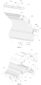
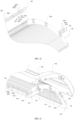
- the electrostatic dust removal apparatus 1 may further include a first positioning element 50 and a second positioning element 60.
- the high-potential conductor 30 is provided on the first positioning element 40, and the first positioning element 50 fits to the conducting end 212 of each of the plurality of high-potential units 21 and the insulating end 221 of each of the plurality of low-potential units 22.
- the low-potential conductor 40 is provided on the second positioning element 60, and the second positioning element 60 fits to the conducting end 212 of each of the plurality of low-potential units 22 and the insulating end 221 of each of the plurality of high-potential units 21.
- the provision of the first positioning element 50 and the second positioning element 60 may fix the high-potential conductor 30 and the low-potential conductor 40 respectively and connect to the plurality of electrode units 20.
- the first positioning element 50 is provided with a plurality of first positioning teeth 510, and each of a plurality of first tooth spaces 520 is formed between the first positioning teeth 510 adjacent to each other.
- the high-potential conductor 30 extends through the first positioning element 50 along the length direction of the first positioning element 50 and is exposed from the plurality of tooth spaces 520.
- Each of the plurality of first positioning teeth 510 is fitted between the conducting end 212 of one high-potential unit 21 and the insulating end 221 of the low-potential unit 22 adjacent to the high-potential unit 21.
- the second positioning element 60 is provided with a plurality of second positioning teeth 610, and each of a plurality of second tooth spaces 620 is formed between the second positioning teeth 610 adjacent to each other.
- the low-potential conductor 40 extends through the second positioning element 60 along the length direction of the second positioning element 60 and is exposed from the plurality of second tooth spaces 620.
- Each of the plurality of second positioning teeth 610 is fitted between the conducting end 212 of one low-potential unit 22 and the insulating end 221 of the high-potential unit 21 adjacent to the low-potential unit 22.
- the plurality of first positioning teeth 510 may have the same width or different widths
- the plurality of second positioning teeth 610 may have the same width or different widths.
- the width of each of the plurality of first positioning teeth 510 and the width of each of the plurality of second positioning teeth 610 may be set based on the spacing between the conducting end 212 of the corresponding high-potential unit 21 and the insulating end 221 of the corresponding low-potential unit 22.
- the width of the tooth top of each of the first positioning tooth 510 and the second positioning tooth 610 can be gradually decreased for convenience of assembly.
- the first positioning element 50 and the second positioning element 60 provided with the high-potential conductor 30 and the low-potential conductor 40 respectively thereon can be assembled with the plurality of electrode units 20, improving the structural stability of the plurality of electrode units 20 and the reliability of the electrical connection.
- the first positioning element 50 is provided with a plurality of first studs 530 spaced apart from each other along its length direction, and the plurality of first studs 530 are mounted onto the frame 10 by a plurality of first screw fasteners (such as screw bolts or screw nails) respectively.
- first screw fasteners such as screw bolts or screw nails
- the second positioning element 60 is provided with a plurality of second studs 630 spaced apart from each other along its length direction, and the plurality of second studs 630 are mounted onto the frame 10 by a plurality of second screw fasteners (such as screw bolts or screw nails) respectively.
- second screw fasteners such as screw bolts or screw nails
- the frame 10 is provided with a plurality of first ribs 550 which are spaced apart from each other and surround the first positioning element 50, and is provided with a plurality of second ribs (not shown in the drawings) which are spaced apart from each other and surround the second positioning element 60.
- the plurality of first ribs 550 may include a first linear rib 551 and two first corner ribs 552, the first linear rib 551 extends along the length direction of the first positioning element 50 and can press against the inner side of the first positioning element 50, and the two first linear ribs 551 can press against two corners at the outer side of the first positioning element 50 respectively.
- the plurality of second ribs include a second linear rib and two second corner ribs, the second linear rib extends along the length direction of the second positioning element 60 and can press against the inner side of the second positioning element 60, and the two corner ribs can press against two corners at the outer side of the second positioning element 60 respectively.
- the first positioning element 50 and the second positioning element 60 can be stably fixed onto the frame 10, realizing a convenient connection and a simplified and reasonable structure.
- each of the first corner rib 552 and the second corner rib may have a different specific structure in a different embodiment.
- the first corner rib 552 and the second corner rib each may be a U-shaped structure; however, in the embodiment shown in FIG. 15 , the first corner rib 552 and the second corner rib each may be an L-shaped structure.
- the one side of the frame 10 described above is provided with a first fixing element 120, and the opposite side of the frame 10 described above is provided with a second fixing element 130.
- the first fixing element 120 is provided with a plurality of first fixing grooves 121 spaced apart from each other along its length direction, and the conducting ends 212 of the plurality of high-potential units 21 and the insulating ends 221 of the plurality of low-potential units 22 are fitted into the plurality of first fixing grooves 121 respectively.
- the second fixing element 130 is provided with a plurality of second fixing grooves 131 spaced apart from each other along its length direction, and the conducting ends 212 of the plurality of low-potential units 22 and the insulating ends 221 of the plurality of high-potential units 21 are fitted into the plurality of second fixing grooves 131 respectively.
- the plurality of electrode units 20 can be fixed onto the frame 10, and the stability of the plurality of electrode units 20 and the uniformity of the spacings among the plurality of electrode units 20 can be guaranteed.
- the first fixing groove 121 has a width gradually increasing from its bottom to its opening
- the second fixing groove 131 has a width gradually increasing from its bottom to its opening.
- the frame 10 is configured as a rectangle-shape which surrounds the plurality of electrode units 20.
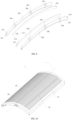
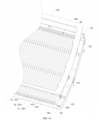
- the electrostatic dust removal apparatus 1 can be bent into an arc shape about an axis L.
- the axis L extends along the length direction of the frame 10 and is located at the middle of the frame 10 in the width direction of the frame 10.
- each of the plurality of electrode units 20 extends along the width direction of the frame 10, the plurality of electrode units 20 are provided spaced apart from each other along the length direction of the frame 10, and the two ends of each of the plurality of electrode units 20 are detachably mounted onto two opposite sides of the frame 10 in the width direction respectively.
- the overall shape of the electrostatic dust removal apparatus 1 is not limited to any particular shape, and the electrostatic dust removal apparatus 1 can be configured as any suitable shape according to a practical application environment.
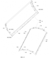
- the frame 10 includes a main frame 150 and a bottom frame 140.
- the bottom frame 140 is detachably mounted onto the main frame 150, and an installation space is defined between the bottom frame 140 and the main frame 150.
- Both ends of each of the plurality of electrode units 20, the first positioning element 50, the second positioning element 60, the high-potential conductor 30, the low-potential conductor 40, the first fixing element 120 and the second fixing element 130 may be provided in the installation space.
- the frame 10 can provide shelter and protection for these structures, allow the appearance of the electrostatic dust removal apparatus 1 more pleasant, and facilitate assembly and disassembly of the overall structure.
- an end positioning structure 110 is formed on both of the main frame 150 and the bottom frame 140, that is, a complete end positioning structure 110 can be formed when the main frame 150 and the bottom frame 140 are in a snap-fit connection.
- the main frame 150 is configured with the first rib 550 and the second rib
- the bottom frame 140 is configured with the first fixing element 120 and the second fixing element 130
- the first positioning element 50 and the second positioning element 60 are mounted on the main frame 150.
- one of the main frame 150 and the bottom frame 140 is provided with a male snap 142 and the other of the main frame 150 and the bottom frame 140 is provided with a female snap 152, and the male snap 142 can be snapped onto the female snap 152.
- a plurality of female snaps 152 may be provided on the main frame 150 and are arranged spaced apart from each other along the circumferential direction of the main frame 150
- a plurality of male snaps 142 may be provided on the bottom frame 140 and are arranged spaced apart from each other along the circumferential direction of the bottom frame 140
- the plurality of male snaps 142 can be snapped into the plurality of female snaps 152 in one-to-one correspondence.
- one of the main frame 150 and the bottom frame 140 is provided with a position-limiting pin 141 and the other of the main frame 150 and the bottom frame 140 is provided with a position-limiting sleeve 151, and the position-limiting pin 141 is configured to be inserted into the position-limiting sleeve 151.
- a plurality of position-limiting pins 141 are arranged on each of two opposite sides of the bottom frame 140 in the length direction of the bottom frame 140 and are spaced apart from each other
- a plurality of position-limiting sleeves 151 are arranged on each of two opposite sides of the main frame 150 in the length direction of the main frame 150 and are spaced apart from each other
- the plurality of position-limiting pins 141 can be inserted into the plurality of position-limiting sleeves 151 in one-to-one correspondence.
- the provision of the position-limiting pin 141 and the position-limiting sleeve 151 may facilitate quick determination of the relative mounting positions of the main frame 150 and the bottom frame 140, that is, may enable pre-positioning, therefore saving time and energy for mounting.
- the male snap 142 and the female snap 152 can make the installation of the main frame 150 and the bottom frame 140 more firm and stable and make the assembly and disassembly of the main frame 150 and the bottom frame 140 more convenient.
- the electrode unit 20 of an electrostatic dust removal apparatus includes a conducting part 210 and an insulating part 220.
- the conducting part 210 is a conductive plastic part and includes an electrical field generator 211 and a conducting end 212.
- the insulating part 220 covers at least a portion of the electrical field generator 211.
- the electrode unit 20 of the electrostatic dust removal apparatus has advantages such as lower manufacture cost, easiness to form various structures, high security and convenience for assembly.
Landscapes
- Electrostatic Separation (AREA)
Claims (13)
- Eine elektrostatische Staubentfernungsvorrichtung (1), umfassend:einen Rahmen (10); undeine Vielzahl von Elektrodeneinheiten (20), die eine Vielzahl von Einheiten mit hohem Potential (21) und eine Vielzahl von Einheiten mit niedrigem Potential (22) umfassen, wobei die Vielzahl von Elektrodeneinheiten (20) auf dem Rahmen (10) vorgesehen und voneinander beabstandet sind, wobei die Vielzahl von Einheiten mit hohem Potential (21) und die Vielzahl von Einheiten mit niedrigem Potential (22) alternierend angeordnet sind, und wobei ein Luftkanal zum Entfernen von Staub zwischen den jeweils benachbarten Elektrodeneinheiten (20) gebildet wird;wobei jede der Vielzahl von Elektrodeneinheiten (20) einen leitenden Teil (210) und einen isolierenden Teil (220) umfasst, der leitende Teil (210) ein leitendes Kunststoffteil ist und einen elektrischen Feldgenerator (211) und ein leitendes Ende (212) umfasst, und der isolierende Teil (220) mindestens einen Teil des elektrischen Feldgenerators (211) abdeckt,wobei die Vielzahl von Elektrodeneinheiten (20) entlang einer Dickenrichtung der Vielzahl von Elektrodeneinheiten (20) angeordnet sind, und zwei Enden jeder der Vielzahl von Elektrodeneinheiten (20) jeweils an zwei gegenüberliegenden Seiten des Rahmens (10) abnehmbar angebracht sind, unddadurch gekennzeichnet, dass die elektrostatische Staubentfernungsvorrichtung (1) ferner umfasst:einen Leiter für hohes Potential (30), der an einer Seite des Rahmens (10) vorgesehen ist, wobei der Leiter für hohes Potential (30) mit dem leitenden Ende (212) jeder der Vielzahl von Einheiten mit hohem Potential (21) verbunden ist; undeinen Leiter für niedriges Potential (40), der an einer anderen Seite des Rahmens (10) vorgesehen ist, die der einen Seite gegenüberliegt, wobei der Leiter für niedriges Potential (40) mit dem leitenden Ende (212) jeder der Vielzahl von Einheiten mit niedrigem Potential (22) verbunden ist.
- Elektrostatische Staubentfernungsvorrichtung (1) nach Anspruch 1, wobei der isolierende Teil (220) den gesamten elektrischen Feldgenerator (211) bedeckt; oder die aneinander angrenzenden elektrischen Feldgeneratoren (211) einander zugewandte Oberflächen haben, wobei eine der Oberflächen von dem isolierenden Teil (220) bedeckt ist und die andere der Oberflächen von dem isolierenden Teil (220) freigelegt ist.
- Elektrostatische Staubentfernungsvorrichtung (1) nach Anspruch 1, wobei der leitende Teil (210) und der isolierende Teil (220) jeder der Vielzahl von Elektrodeneinheiten (20) aus einem Stück durch Spritzgießen gebildet werden.
- Elektrostatische Staubentfernungsvorrichtung (1) nach einem der Ansprüche 1 bis 3, wobei eine der aneinander angrenzenden Elektrodeneinheiten (20) mit einem Positionierungsring (240) versehen ist und die andere der aneinander angrenzenden Elektrodeneinheiten (20) mit einem Positionierungsvorsprung (230) versehen ist, der so konfiguriert ist, dass er in den Positionierungsring (240) eingesetzt werden kann.
- Elektrostatische Staubentfernungsvorrichtung (1) nach Anspruch 4, wobei eine Endpositionierungsstruktur (110) an dem Rahmen (10) vorgesehen ist und der Positionierungsring (240) oder der Positionierungsvorsprung (230) der äußersten Elektrodeneinheit (20) zu der Endpositionierungsstruktur (110) passt.
- Elektrostatische Staubentfernungsvorrichtung (1) nach Anspruch 1, wobei ein Ende der Einheit mit hohem Potential (21) das leitende Ende (212) ist, das von dem leitenden Teil (210) der Einheit mit hohem Potential (21) gebildet wird, und das andere Ende der Einheit mit hohem Potential (21) ein isolierendes Ende (221) ist, das von dem isolierenden Teil (220) der Einheit mit hohem Potential (21) gebildet wird, undein Ende der Einheit mit niedrigem Potential (22) das leitende Ende (212) ist, das von dem leitenden Teil (210) der Einheit mit niedrigem Potential (22) gebildet wird, und das andere Ende der Einheit mit niedrigem Potential (22) ein isolierendes Ende (221) ist, das von dem isolierenden Teil (220) der Einheit mit niedrigem Potential (22) gebildet wird,wobei die leitenden Enden (212) der Vielzahl von Einheiten mit hohem Potential (21) und die isolierenden Enden (221) der Vielzahl von Einheiten mit niedrigem Potential (22) der einen Seite des Rahmens (10) zugewandt sind, und die isolierenden Enden (221) der Vielzahl von Einheiten mit hohem Potential (21) und die leitenden Enden (212) der Vielzahl von Einheiten mit niedrigem Potential (22) der anderen Seite des Rahmens (10) zugewandt sind, die der einen Seite gegenüberliegt.
- Elektrostatische Staubentfernungsvorrichtung (1) nach Anspruch 6, wobei der Leiter für hohes Potential (30) mit dem isolierenden Ende (221) jeder der Vielzahl von Einheiten mit niedrigem Potential (22) verbunden ist; und
der Leiter für niedriges Potential (40) mit dem isolierenden Ende (221) jeder der Vielzahl von Einheiten mit hohem Potential (21) verbunden ist. - Elektrostatische Staubentfernungsvorrichtung (1) nach Anspruch 7, wobei die elektrostatische Staubentfernungsvorrichtung (1) ferner umfasst:ein erstes Positionierungselement (50), wobei der Leiter für hohes Potential (30) auf dem ersten Positionierungselement (50) vorgesehen ist und das erste Positionierungselement (50) an das leitende Ende (212) jeder der Vielzahl von Einheiten mit hohem Potential (21) und das isolierende Ende (221) jeder der Vielzahl von Einheiten mit niedrigem Potential (22) passt; undein zweites Positionierungselement (60), wobei der Leiter für niedriges Potential (40) auf dem zweiten Positionierungselement (60) vorgesehen ist und das zweite Positionierungselement (60) an das leitende Ende (212) jeder der Vielzahl von Einheiten mit niedrigem Potential (22) und das isolierende Ende (221) jeder der Vielzahl von Einheiten mit hohem Potential (21) passt.
- Elektrostatische Staubentfernungsvorrichtung (1) nach Anspruch 8, wobei das erste Positionierungselement (50) mit einer Vielzahl von ersten Positionierungszähnen (510) versehen ist, wobei jede einer Vielzahl von ersten Zahnlücken (520) zwischen den jeweils benachbarten ersten Positionierungszähnen (510) gebildet wird, der Leiter für hohes Potential (30) sich durch das erste Positionierungselement (50) erstreckt und von der Vielzahl der ersten Zahnlücken (520) freigelegt ist, und jeder der Vielzahl der ersten Positionierungszähne (510) zwischen dem leitenden Ende (212) einer Einheit mit hohem Potential (21) und dem isolierenden Ende (221) der Einheit mit niedrigem Potential (22) benachbart zu der einen Einheit mit hohem Potential (21) eingepasst ist; und
das zweite Positionierungselement (60) mit einer Vielzahl von zweiten Positionierungszähnen (610) versehen ist, wobei jede einer Vielzahl von zweiten Zahnlücken (620) zwischen den jeweils benachbarten zweiten Positionierungszähnen (610) gebildet wird, der Leiter für niedriges Potential (40) sich durch das zweite Positionierungselement (60) erstreckt und von der Vielzahl der zweiten Zahnlücken (620) freigelegt ist, und jeder der Vielzahl der zweiten Positionierungszähne (610) zwischen dem leitenden Ende (212) einer Einheit mit niedrigem Potential (22) und dem isolierenden Ende (221) der Einheit mit hohem Potential (21) benachbart zu der einen Einheit mit niedrigem Potential (22) eingepasst ist. - Elektrostatische Staubentfernungsvorrichtung (1) nach Anspruch 9, wobei das leitende Ende (212) jeder der Vielzahl von Einheiten mit hohem Potential (21) und das isolierende Ende (221) jeder der Vielzahl von Einheiten mit niedrigem Potential (22) jeweils mit einer ersten Positionierungsnut (231) versehen sind und das erste Positionierungselement (50) in eine Vielzahl erster Positionierungsnuten (231) eingepasst ist, und
das leitende Ende (212) jeder der Vielzahl von Einheiten mit niedrigem Potential (22) und das isolierende Ende (221) jeder der Vielzahl von Einheiten mit hohem Potential (21) jeweils mit einer zweiten Positionierungsnut (232) versehen sind und das zweite Positionierungselement (60) in eine Vielzahl zweiter Positionierungsnuten (232) eingepasst ist. - Elektrostatische Staubentfernungsvorrichtung (1) nach Anspruch 8, wobei das erste Positionierungselement (50) mit einer Vielzahl von ersten Stiften (530) versehen ist, die entlang seiner Längsrichtung voneinander beabstandet sind, und die Vielzahl von ersten Stiften (530) jeweils durch eine Vielzahl von ersten Schraubbefestigungen an dem Rahmen (10) angebracht sind; und
das zweite Positionierelement (60) mit einer Vielzahl von zweiten Stiften (630) versehen ist, die entlang seiner Längsrichtung voneinander beabstandet sind, und die Vielzahl von zweiten Stiften (630) jeweils durch eine Vielzahl von zweiten Schraubbefestigungen an dem Rahmen (10) angebracht sind. - Elektrostatische Staubentfernungsvorrichtung (1) nach Anspruch 8, wobei der Rahmen (10) mit einer Vielzahl von ersten Rippen (550) versehen ist, die voneinander beabstandet sind und das erste Positionierungselement (50) umgeben, und mit einer Vielzahl von zweiten Rippen versehen ist, die voneinander beabstandet sind und das zweite Positionierungselement (60) umgeben.
- Elektrostatische Staubentfernungsvorrichtung (1) nach einem der Ansprüche 1 bis 12, wobei der Rahmen (10) in Rechteckform konfiguriert ist, die die Vielzahl von Elektrodeneinheiten (20) umgibt;jede der Vielzahl von Elektrodeneinheiten (20) sich entlang einer Breitenrichtung des Rahmens (10) erstreckt, die Vielzahl von Elektrodeneinheiten (20) voneinander beabstandet entlang einer Längsrichtung des Rahmens (10) vorgesehen sind, und zwei Enden jeder der Vielzahl von Elektrodeneinheiten (20) jeweils abnehmbar an zwei gegenüberliegenden Seiten des Rahmens (10) in der Breitenrichtung angebracht sind; unddie elektrostatische Staubentfernungsvorrichtung (1) in eine Bogenform um eine Achse (L) gebogen ist, wobei sich die Achse (L) entlang der Längsrichtung des Rahmens (10) erstreckt und in der Mitte des Rahmens (10) in der Breitenrichtung des Rahmens (10) angeordnet ist.
Applications Claiming Priority (2)
| Application Number | Priority Date | Filing Date | Title |
|---|---|---|---|
| CN201910762346.8A CN110639703B (zh) | 2019-08-19 | 2019-08-19 | 静电除尘装置及其电极单元 |
| PCT/CN2020/109768 WO2021032080A1 (zh) | 2019-08-19 | 2020-08-18 | 静电除尘装置及其电极单元 |
Publications (3)
| Publication Number | Publication Date |
|---|---|
| EP4000737A1 EP4000737A1 (de) | 2022-05-25 |
| EP4000737A4 EP4000737A4 (de) | 2022-10-05 |
| EP4000737B1 true EP4000737B1 (de) | 2023-12-13 |
Family
ID=68990217
Family Applications (1)
| Application Number | Title | Priority Date | Filing Date |
|---|---|---|---|
| EP20854082.3A Active EP4000737B1 (de) | 2019-08-19 | 2020-08-18 | Elektrostatisches staubentfernungsgerät |
Country Status (4)
| Country | Link |
|---|---|
| US (1) | US12377422B2 (de) |
| EP (1) | EP4000737B1 (de) |
| CN (1) | CN110639703B (de) |
| WO (1) | WO2021032080A1 (de) |
Families Citing this family (5)
| Publication number | Priority date | Publication date | Assignee | Title |
|---|---|---|---|---|
| CN110639701A (zh) * | 2019-08-19 | 2020-01-03 | 佛山市顺德区阿波罗环保器材有限公司 | 静电除尘装置及其电极单元 |
| CN110639703B (zh) * | 2019-08-19 | 2025-10-28 | 佛山市顺德区阿波罗环保器材有限公司 | 静电除尘装置及其电极单元 |
| WO2021258522A1 (zh) * | 2020-06-22 | 2021-12-30 | 佛山市顺德区阿波罗环保器材有限公司 | 静电除尘装置 |
| WO2022028167A1 (zh) * | 2020-08-07 | 2022-02-10 | 佛山市顺德区阿波罗环保器材有限公司 | 静电除尘装置和具有其的空气净化器 |
| CN113145312B (zh) * | 2021-03-19 | 2024-10-25 | 珠海格力电器股份有限公司 | 一种集尘件单体及集尘装置及空气净化器 |
Family Cites Families (19)
| Publication number | Priority date | Publication date | Assignee | Title |
|---|---|---|---|---|
| JP2008227474A (ja) * | 2007-02-13 | 2008-09-25 | Toshiba Corp | 半導体装置 |
| IL182389A (en) * | 2007-04-10 | 2010-11-30 | Yefim Riskin | Method of air purification from dust and electrostatic filter |
| CN204074260U (zh) * | 2013-07-19 | 2015-01-07 | 张方敏 | 静电集尘箱 |
| CN203778200U (zh) * | 2014-04-28 | 2014-08-20 | 聂振杰 | 一种新型空气净化装置 |
| US9914134B2 (en) * | 2014-07-31 | 2018-03-13 | Trane International Inc. | Systems and methods for cleaning air |
| CN105195326B (zh) * | 2015-11-04 | 2018-02-27 | 珠海格力电器股份有限公司 | 一种静电式空气净化器及其电净化部件 |
| CN105363557B (zh) * | 2015-12-03 | 2017-08-15 | 宁波哲恺电器有限公司 | 静电集尘模块及其静电式空气净化器 |
| CN106925428A (zh) * | 2015-12-29 | 2017-07-07 | 汉王科技股份有限公司 | 静电空气净化器 |
| CN105689135B (zh) * | 2016-04-14 | 2018-05-22 | 颜为 | 一种具有弧形电极片的集尘装置 |
| CN205701054U (zh) * | 2016-04-15 | 2016-11-23 | 广东顺德惠美庄电器实业有限公司 | 一种静电集尘装置 |
| CN206276499U (zh) * | 2016-12-10 | 2017-06-27 | 南京复苏等离子科技有限公司 | 一种集尘装置 |
| CN107626451B (zh) * | 2017-10-24 | 2025-04-08 | 苏州贝昂智能科技股份有限公司 | 座体及集尘器 |
| CN207756285U (zh) * | 2018-04-08 | 2018-08-24 | 广东美的制冷设备有限公司 | 静电除尘装置、空调室内机及空调器 |
| CN108855621A (zh) * | 2018-06-07 | 2018-11-23 | 汉王科技股份有限公司 | 静电集尘片的加工方法、静电集尘片和静电集尘器 |
| CN208115989U (zh) * | 2018-06-07 | 2018-11-20 | 汉王科技股份有限公司 | 静电集尘片和静电集尘器 |
| CN211865443U (zh) * | 2019-08-19 | 2020-11-06 | 佛山市顺德区阿波罗环保器材有限公司 | 静电除尘装置及其电极单元 |
| CN110639701A (zh) * | 2019-08-19 | 2020-01-03 | 佛山市顺德区阿波罗环保器材有限公司 | 静电除尘装置及其电极单元 |
| CN110639702A (zh) * | 2019-08-19 | 2020-01-03 | 佛山市顺德区阿波罗环保器材有限公司 | 静电除尘装置及其电极单元 |
| CN110639703B (zh) * | 2019-08-19 | 2025-10-28 | 佛山市顺德区阿波罗环保器材有限公司 | 静电除尘装置及其电极单元 |
-
2019
- 2019-08-19 CN CN201910762346.8A patent/CN110639703B/zh active Active
-
2020
- 2020-08-18 WO PCT/CN2020/109768 patent/WO2021032080A1/zh not_active Ceased
- 2020-08-18 EP EP20854082.3A patent/EP4000737B1/de active Active
-
2022
- 2022-02-18 US US17/651,608 patent/US12377422B2/en active Active
Also Published As
| Publication number | Publication date |
|---|---|
| CN110639703B (zh) | 2025-10-28 |
| EP4000737A1 (de) | 2022-05-25 |
| EP4000737A4 (de) | 2022-10-05 |
| US12377422B2 (en) | 2025-08-05 |
| CN110639703A (zh) | 2020-01-03 |
| US20220168753A1 (en) | 2022-06-02 |
| WO2021032080A1 (zh) | 2021-02-25 |
Similar Documents
| Publication | Publication Date | Title |
|---|---|---|
| EP4000737B1 (de) | Elektrostatisches staubentfernungsgerät | |
| US10744516B2 (en) | Electrostatic dust collecting module an electrostatic air purifier thereof | |
| JP6029860B2 (ja) | 電気集塵装置 | |
| CN110639702A (zh) | 静电除尘装置及其电极单元 | |
| WO2021032081A1 (zh) | 静电除尘装置及其电极单元 | |
| EP3025364A1 (de) | Modulare röntgenquelle | |
| CN111359779A (zh) | 电净化组件、空气净化器 | |
| CN215197591U (zh) | 静电除尘装置及其净化器 | |
| CN211865443U (zh) | 静电除尘装置及其电极单元 | |
| CN214262333U (zh) | 一种圆管通道针净化灭菌模块 | |
| CN213943531U (zh) | 静电除尘装置 | |
| CN211636937U (zh) | 静电除尘装置及其电极单元 | |
| CN211636938U (zh) | 静电除尘装置及其电极单元 | |
| CN218013371U (zh) | 集尘组件及具有其的空气净化装置 | |
| CN111569619A (zh) | 电净化结构、电净化组件、空气净化装置 | |
| CN213331606U (zh) | 台式风扇 | |
| WO2021258522A1 (zh) | 静电除尘装置 | |
| CN110328053A (zh) | 静电除尘装置及空气净化器 | |
| CN211989170U (zh) | 电净化组件、空气净化器 | |
| CN213529122U (zh) | 一种极板式电场 | |
| CN213480514U (zh) | 电净化组件、空气净化设备 | |
| CN209882187U (zh) | 一种静电消除器接地结构 | |
| CN213331595U (zh) | 风扇 | |
| CN211756009U (zh) | 一种用于静电除尘器的片式阴极线 | |
| KR102583486B1 (ko) | 전기집진장치 |
Legal Events
| Date | Code | Title | Description |
|---|---|---|---|
| STAA | Information on the status of an ep patent application or granted ep patent |
Free format text: STATUS: THE INTERNATIONAL PUBLICATION HAS BEEN MADE |
|
| PUAI | Public reference made under article 153(3) epc to a published international application that has entered the european phase |
Free format text: ORIGINAL CODE: 0009012 |
|
| STAA | Information on the status of an ep patent application or granted ep patent |
Free format text: STATUS: REQUEST FOR EXAMINATION WAS MADE |
|
| 17P | Request for examination filed |
Effective date: 20220218 |
|
| AK | Designated contracting states |
Kind code of ref document: A1 Designated state(s): AL AT BE BG CH CY CZ DE DK EE ES FI FR GB GR HR HU IE IS IT LI LT LU LV MC MK MT NL NO PL PT RO RS SE SI SK SM TR |
|
| A4 | Supplementary search report drawn up and despatched |
Effective date: 20220906 |
|
| RIC1 | Information provided on ipc code assigned before grant |
Ipc: B03C 3/86 20060101ALI20220831BHEP Ipc: B03C 3/64 20060101ALI20220831BHEP Ipc: B03C 3/08 20060101ALI20220831BHEP Ipc: B03C 3/47 20060101ALI20220831BHEP Ipc: B03C 3/34 20060101ALI20220831BHEP Ipc: B03C 3/70 20060101ALI20220831BHEP Ipc: B03C 3/40 20060101ALI20220831BHEP Ipc: B03C 3/04 20060101AFI20220831BHEP |
|
| DAV | Request for validation of the european patent (deleted) | ||
| DAX | Request for extension of the european patent (deleted) | ||
| GRAP | Despatch of communication of intention to grant a patent |
Free format text: ORIGINAL CODE: EPIDOSNIGR1 |
|
| STAA | Information on the status of an ep patent application or granted ep patent |
Free format text: STATUS: GRANT OF PATENT IS INTENDED |
|
| RIC1 | Information provided on ipc code assigned before grant |
Ipc: B03C 3/86 20060101ALI20230621BHEP Ipc: B03C 3/64 20060101ALI20230621BHEP Ipc: B03C 3/08 20060101ALI20230621BHEP Ipc: B03C 3/47 20060101ALI20230621BHEP Ipc: B03C 3/34 20060101ALI20230621BHEP Ipc: B03C 3/70 20060101ALI20230621BHEP Ipc: B03C 3/40 20060101ALI20230621BHEP Ipc: B03C 3/04 20060101AFI20230621BHEP |
|
| INTG | Intention to grant announced |
Effective date: 20230707 |
|
| GRAS | Grant fee paid |
Free format text: ORIGINAL CODE: EPIDOSNIGR3 |
|
| GRAA | (expected) grant |
Free format text: ORIGINAL CODE: 0009210 |
|
| STAA | Information on the status of an ep patent application or granted ep patent |
Free format text: STATUS: THE PATENT HAS BEEN GRANTED |
|
| AK | Designated contracting states |
Kind code of ref document: B1 Designated state(s): AL AT BE BG CH CY CZ DE DK EE ES FI FR GB GR HR HU IE IS IT LI LT LU LV MC MK MT NL NO PL PT RO RS SE SI SK SM TR |
|
| REG | Reference to a national code |
Ref country code: GB Ref legal event code: FG4D |
|
| REG | Reference to a national code |
Ref country code: CH Ref legal event code: EP |
|
| REG | Reference to a national code |
Ref country code: DE Ref legal event code: R096 Ref document number: 602020022866 Country of ref document: DE |
|
| REG | Reference to a national code |
Ref country code: IE Ref legal event code: FG4D |
|
| PG25 | Lapsed in a contracting state [announced via postgrant information from national office to epo] |
Ref country code: GR Free format text: LAPSE BECAUSE OF FAILURE TO SUBMIT A TRANSLATION OF THE DESCRIPTION OR TO PAY THE FEE WITHIN THE PRESCRIBED TIME-LIMIT Effective date: 20240314 |
|
| REG | Reference to a national code |
Ref country code: LT Ref legal event code: MG9D |
|
| PG25 | Lapsed in a contracting state [announced via postgrant information from national office to epo] |
Ref country code: LT Free format text: LAPSE BECAUSE OF FAILURE TO SUBMIT A TRANSLATION OF THE DESCRIPTION OR TO PAY THE FEE WITHIN THE PRESCRIBED TIME-LIMIT Effective date: 20231213 |
|
| REG | Reference to a national code |
Ref country code: NL Ref legal event code: MP Effective date: 20231213 |
|
| PG25 | Lapsed in a contracting state [announced via postgrant information from national office to epo] |
Ref country code: ES Free format text: LAPSE BECAUSE OF FAILURE TO SUBMIT A TRANSLATION OF THE DESCRIPTION OR TO PAY THE FEE WITHIN THE PRESCRIBED TIME-LIMIT Effective date: 20231213 |
|
| PG25 | Lapsed in a contracting state [announced via postgrant information from national office to epo] |
Ref country code: LT Free format text: LAPSE BECAUSE OF FAILURE TO SUBMIT A TRANSLATION OF THE DESCRIPTION OR TO PAY THE FEE WITHIN THE PRESCRIBED TIME-LIMIT Effective date: 20231213 Ref country code: GR Free format text: LAPSE BECAUSE OF FAILURE TO SUBMIT A TRANSLATION OF THE DESCRIPTION OR TO PAY THE FEE WITHIN THE PRESCRIBED TIME-LIMIT Effective date: 20240314 Ref country code: ES Free format text: LAPSE BECAUSE OF FAILURE TO SUBMIT A TRANSLATION OF THE DESCRIPTION OR TO PAY THE FEE WITHIN THE PRESCRIBED TIME-LIMIT Effective date: 20231213 Ref country code: BG Free format text: LAPSE BECAUSE OF FAILURE TO SUBMIT A TRANSLATION OF THE DESCRIPTION OR TO PAY THE FEE WITHIN THE PRESCRIBED TIME-LIMIT Effective date: 20240313 |
|
| REG | Reference to a national code |
Ref country code: AT Ref legal event code: MK05 Ref document number: 1640034 Country of ref document: AT Kind code of ref document: T Effective date: 20231213 |
|
| PG25 | Lapsed in a contracting state [announced via postgrant information from national office to epo] |
Ref country code: NL Free format text: LAPSE BECAUSE OF FAILURE TO SUBMIT A TRANSLATION OF THE DESCRIPTION OR TO PAY THE FEE WITHIN THE PRESCRIBED TIME-LIMIT Effective date: 20231213 |
|
| PG25 | Lapsed in a contracting state [announced via postgrant information from national office to epo] |
Ref country code: SE Free format text: LAPSE BECAUSE OF FAILURE TO SUBMIT A TRANSLATION OF THE DESCRIPTION OR TO PAY THE FEE WITHIN THE PRESCRIBED TIME-LIMIT Effective date: 20231213 Ref country code: RS Free format text: LAPSE BECAUSE OF FAILURE TO SUBMIT A TRANSLATION OF THE DESCRIPTION OR TO PAY THE FEE WITHIN THE PRESCRIBED TIME-LIMIT Effective date: 20231213 Ref country code: NO Free format text: LAPSE BECAUSE OF FAILURE TO SUBMIT A TRANSLATION OF THE DESCRIPTION OR TO PAY THE FEE WITHIN THE PRESCRIBED TIME-LIMIT Effective date: 20240313 Ref country code: NL Free format text: LAPSE BECAUSE OF FAILURE TO SUBMIT A TRANSLATION OF THE DESCRIPTION OR TO PAY THE FEE WITHIN THE PRESCRIBED TIME-LIMIT Effective date: 20231213 Ref country code: LV Free format text: LAPSE BECAUSE OF FAILURE TO SUBMIT A TRANSLATION OF THE DESCRIPTION OR TO PAY THE FEE WITHIN THE PRESCRIBED TIME-LIMIT Effective date: 20231213 Ref country code: HR Free format text: LAPSE BECAUSE OF FAILURE TO SUBMIT A TRANSLATION OF THE DESCRIPTION OR TO PAY THE FEE WITHIN THE PRESCRIBED TIME-LIMIT Effective date: 20231213 |
|
| PG25 | Lapsed in a contracting state [announced via postgrant information from national office to epo] |
Ref country code: IS Free format text: LAPSE BECAUSE OF FAILURE TO SUBMIT A TRANSLATION OF THE DESCRIPTION OR TO PAY THE FEE WITHIN THE PRESCRIBED TIME-LIMIT Effective date: 20240413 |
|
| PG25 | Lapsed in a contracting state [announced via postgrant information from national office to epo] |
Ref country code: AT Free format text: LAPSE BECAUSE OF FAILURE TO SUBMIT A TRANSLATION OF THE DESCRIPTION OR TO PAY THE FEE WITHIN THE PRESCRIBED TIME-LIMIT Effective date: 20231213 Ref country code: CZ Free format text: LAPSE BECAUSE OF FAILURE TO SUBMIT A TRANSLATION OF THE DESCRIPTION OR TO PAY THE FEE WITHIN THE PRESCRIBED TIME-LIMIT Effective date: 20231213 |
|
| PG25 | Lapsed in a contracting state [announced via postgrant information from national office to epo] |
Ref country code: SK Free format text: LAPSE BECAUSE OF FAILURE TO SUBMIT A TRANSLATION OF THE DESCRIPTION OR TO PAY THE FEE WITHIN THE PRESCRIBED TIME-LIMIT Effective date: 20231213 |
|
| PG25 | Lapsed in a contracting state [announced via postgrant information from national office to epo] |
Ref country code: SM Free format text: LAPSE BECAUSE OF FAILURE TO SUBMIT A TRANSLATION OF THE DESCRIPTION OR TO PAY THE FEE WITHIN THE PRESCRIBED TIME-LIMIT Effective date: 20231213 Ref country code: SK Free format text: LAPSE BECAUSE OF FAILURE TO SUBMIT A TRANSLATION OF THE DESCRIPTION OR TO PAY THE FEE WITHIN THE PRESCRIBED TIME-LIMIT Effective date: 20231213 Ref country code: RO Free format text: LAPSE BECAUSE OF FAILURE TO SUBMIT A TRANSLATION OF THE DESCRIPTION OR TO PAY THE FEE WITHIN THE PRESCRIBED TIME-LIMIT Effective date: 20231213 Ref country code: IT Free format text: LAPSE BECAUSE OF FAILURE TO SUBMIT A TRANSLATION OF THE DESCRIPTION OR TO PAY THE FEE WITHIN THE PRESCRIBED TIME-LIMIT Effective date: 20231213 Ref country code: IS Free format text: LAPSE BECAUSE OF FAILURE TO SUBMIT A TRANSLATION OF THE DESCRIPTION OR TO PAY THE FEE WITHIN THE PRESCRIBED TIME-LIMIT Effective date: 20240413 Ref country code: EE Free format text: LAPSE BECAUSE OF FAILURE TO SUBMIT A TRANSLATION OF THE DESCRIPTION OR TO PAY THE FEE WITHIN THE PRESCRIBED TIME-LIMIT Effective date: 20231213 Ref country code: CZ Free format text: LAPSE BECAUSE OF FAILURE TO SUBMIT A TRANSLATION OF THE DESCRIPTION OR TO PAY THE FEE WITHIN THE PRESCRIBED TIME-LIMIT Effective date: 20231213 Ref country code: AT Free format text: LAPSE BECAUSE OF FAILURE TO SUBMIT A TRANSLATION OF THE DESCRIPTION OR TO PAY THE FEE WITHIN THE PRESCRIBED TIME-LIMIT Effective date: 20231213 |
|
| PG25 | Lapsed in a contracting state [announced via postgrant information from national office to epo] |
Ref country code: PT Free format text: LAPSE BECAUSE OF FAILURE TO SUBMIT A TRANSLATION OF THE DESCRIPTION OR TO PAY THE FEE WITHIN THE PRESCRIBED TIME-LIMIT Effective date: 20240415 Ref country code: PL Free format text: LAPSE BECAUSE OF FAILURE TO SUBMIT A TRANSLATION OF THE DESCRIPTION OR TO PAY THE FEE WITHIN THE PRESCRIBED TIME-LIMIT Effective date: 20231213 |
|
| PG25 | Lapsed in a contracting state [announced via postgrant information from national office to epo] |
Ref country code: PT Free format text: LAPSE BECAUSE OF FAILURE TO SUBMIT A TRANSLATION OF THE DESCRIPTION OR TO PAY THE FEE WITHIN THE PRESCRIBED TIME-LIMIT Effective date: 20240415 Ref country code: PL Free format text: LAPSE BECAUSE OF FAILURE TO SUBMIT A TRANSLATION OF THE DESCRIPTION OR TO PAY THE FEE WITHIN THE PRESCRIBED TIME-LIMIT Effective date: 20231213 |
|
| REG | Reference to a national code |
Ref country code: DE Ref legal event code: R097 Ref document number: 602020022866 Country of ref document: DE |
|
| PG25 | Lapsed in a contracting state [announced via postgrant information from national office to epo] |
Ref country code: DK Free format text: LAPSE BECAUSE OF FAILURE TO SUBMIT A TRANSLATION OF THE DESCRIPTION OR TO PAY THE FEE WITHIN THE PRESCRIBED TIME-LIMIT Effective date: 20231213 |
|
| PLBE | No opposition filed within time limit |
Free format text: ORIGINAL CODE: 0009261 |
|
| STAA | Information on the status of an ep patent application or granted ep patent |
Free format text: STATUS: NO OPPOSITION FILED WITHIN TIME LIMIT |
|
| PG25 | Lapsed in a contracting state [announced via postgrant information from national office to epo] |
Ref country code: SI Free format text: LAPSE BECAUSE OF FAILURE TO SUBMIT A TRANSLATION OF THE DESCRIPTION OR TO PAY THE FEE WITHIN THE PRESCRIBED TIME-LIMIT Effective date: 20231213 |
|
| PG25 | Lapsed in a contracting state [announced via postgrant information from national office to epo] |
Ref country code: SI Free format text: LAPSE BECAUSE OF FAILURE TO SUBMIT A TRANSLATION OF THE DESCRIPTION OR TO PAY THE FEE WITHIN THE PRESCRIBED TIME-LIMIT Effective date: 20231213 Ref country code: DK Free format text: LAPSE BECAUSE OF FAILURE TO SUBMIT A TRANSLATION OF THE DESCRIPTION OR TO PAY THE FEE WITHIN THE PRESCRIBED TIME-LIMIT Effective date: 20231213 |
|
| 26N | No opposition filed |
Effective date: 20240916 |
|
| REG | Reference to a national code |
Ref country code: CH Ref legal event code: PL |
|
| PG25 | Lapsed in a contracting state [announced via postgrant information from national office to epo] |
Ref country code: LU Free format text: LAPSE BECAUSE OF NON-PAYMENT OF DUE FEES Effective date: 20240818 |
|
| GBPC | Gb: european patent ceased through non-payment of renewal fee |
Effective date: 20240818 |
|
| PG25 | Lapsed in a contracting state [announced via postgrant information from national office to epo] |
Ref country code: CH Free format text: LAPSE BECAUSE OF NON-PAYMENT OF DUE FEES Effective date: 20240831 Ref country code: MC Free format text: LAPSE BECAUSE OF FAILURE TO SUBMIT A TRANSLATION OF THE DESCRIPTION OR TO PAY THE FEE WITHIN THE PRESCRIBED TIME-LIMIT Effective date: 20231213 |
|
| REG | Reference to a national code |
Ref country code: BE Ref legal event code: MM Effective date: 20240831 |
|
| PG25 | Lapsed in a contracting state [announced via postgrant information from national office to epo] |
Ref country code: GB Free format text: LAPSE BECAUSE OF NON-PAYMENT OF DUE FEES Effective date: 20240818 |
|
| PG25 | Lapsed in a contracting state [announced via postgrant information from national office to epo] |
Ref country code: BE Free format text: LAPSE BECAUSE OF NON-PAYMENT OF DUE FEES Effective date: 20240831 |
|
| PG25 | Lapsed in a contracting state [announced via postgrant information from national office to epo] |
Ref country code: IE Free format text: LAPSE BECAUSE OF NON-PAYMENT OF DUE FEES Effective date: 20240818 |
|
| PG25 | Lapsed in a contracting state [announced via postgrant information from national office to epo] |
Ref country code: FI Free format text: LAPSE BECAUSE OF FAILURE TO SUBMIT A TRANSLATION OF THE DESCRIPTION OR TO PAY THE FEE WITHIN THE PRESCRIBED TIME-LIMIT Effective date: 20231213 |
|
| PGFP | Annual fee paid to national office [announced via postgrant information from national office to epo] |
Ref country code: DE Payment date: 20250812 Year of fee payment: 6 |
|
| PGFP | Annual fee paid to national office [announced via postgrant information from national office to epo] |
Ref country code: FR Payment date: 20250828 Year of fee payment: 6 |
|
| PG25 | Lapsed in a contracting state [announced via postgrant information from national office to epo] |
Ref country code: CY Free format text: LAPSE BECAUSE OF FAILURE TO SUBMIT A TRANSLATION OF THE DESCRIPTION OR TO PAY THE FEE WITHIN THE PRESCRIBED TIME-LIMIT; INVALID AB INITIO Effective date: 20200818 |
|
| PG25 | Lapsed in a contracting state [announced via postgrant information from national office to epo] |
Ref country code: HU Free format text: LAPSE BECAUSE OF FAILURE TO SUBMIT A TRANSLATION OF THE DESCRIPTION OR TO PAY THE FEE WITHIN THE PRESCRIBED TIME-LIMIT; INVALID AB INITIO Effective date: 20200818 |