EP4000773B1 - Vorrichtung zur generativen fertigung mit akusto-optischem deflektor und zugehörige verfahren - Google Patents
Vorrichtung zur generativen fertigung mit akusto-optischem deflektor und zugehörige verfahren Download PDFInfo
- Publication number
- EP4000773B1 EP4000773B1 EP21202536.5A EP21202536A EP4000773B1 EP 4000773 B1 EP4000773 B1 EP 4000773B1 EP 21202536 A EP21202536 A EP 21202536A EP 4000773 B1 EP4000773 B1 EP 4000773B1
- Authority
- EP
- European Patent Office
- Prior art keywords
- aod
- scan
- controller
- build material
- additive manufacturing
- Prior art date
- Legal status (The legal status is an assumption and is not a legal conclusion. Google has not performed a legal analysis and makes no representation as to the accuracy of the status listed.)
- Active
Links
Images



Classifications
-
- B—PERFORMING OPERATIONS; TRANSPORTING
- B29—WORKING OF PLASTICS; WORKING OF SUBSTANCES IN A PLASTIC STATE IN GENERAL
- B29C—SHAPING OR JOINING OF PLASTICS; SHAPING OF MATERIAL IN A PLASTIC STATE, NOT OTHERWISE PROVIDED FOR; AFTER-TREATMENT OF THE SHAPED PRODUCTS, e.g. REPAIRING
- B29C64/00—Additive manufacturing, i.e. manufacturing of three-dimensional [3D] objects by additive deposition, additive agglomeration or additive layering, e.g. by 3D printing, stereolithography or selective laser sintering
- B29C64/10—Processes of additive manufacturing
- B29C64/106—Processes of additive manufacturing using only liquids or viscous materials, e.g. depositing a continuous bead of viscous material
- B29C64/124—Processes of additive manufacturing using only liquids or viscous materials, e.g. depositing a continuous bead of viscous material using layers of liquid which are selectively solidified
- B29C64/129—Processes of additive manufacturing using only liquids or viscous materials, e.g. depositing a continuous bead of viscous material using layers of liquid which are selectively solidified characterised by the energy source therefor, e.g. by global irradiation combined with a mask
- B29C64/135—Processes of additive manufacturing using only liquids or viscous materials, e.g. depositing a continuous bead of viscous material using layers of liquid which are selectively solidified characterised by the energy source therefor, e.g. by global irradiation combined with a mask the energy source being concentrated, e.g. scanning lasers or focused light sources
-
- B—PERFORMING OPERATIONS; TRANSPORTING
- B22—CASTING; POWDER METALLURGY
- B22F—WORKING METALLIC POWDER; MANUFACTURE OF ARTICLES FROM METALLIC POWDER; MAKING METALLIC POWDER; APPARATUS OR DEVICES SPECIALLY ADAPTED FOR METALLIC POWDER
- B22F10/00—Additive manufacturing of workpieces or articles from metallic powder
- B22F10/20—Direct sintering or melting
-
- B—PERFORMING OPERATIONS; TRANSPORTING
- B22—CASTING; POWDER METALLURGY
- B22F—WORKING METALLIC POWDER; MANUFACTURE OF ARTICLES FROM METALLIC POWDER; MAKING METALLIC POWDER; APPARATUS OR DEVICES SPECIALLY ADAPTED FOR METALLIC POWDER
- B22F10/00—Additive manufacturing of workpieces or articles from metallic powder
- B22F10/30—Process control
- B22F10/36—Process control of energy beam parameters
- B22F10/366—Scanning parameters, e.g. hatch distance or scanning strategy
-
- B—PERFORMING OPERATIONS; TRANSPORTING
- B22—CASTING; POWDER METALLURGY
- B22F—WORKING METALLIC POWDER; MANUFACTURE OF ARTICLES FROM METALLIC POWDER; MAKING METALLIC POWDER; APPARATUS OR DEVICES SPECIALLY ADAPTED FOR METALLIC POWDER
- B22F12/00—Apparatus or devices specially adapted for additive manufacturing; Auxiliary means for additive manufacturing; Combinations of additive manufacturing apparatus or devices with other processing apparatus or devices
- B22F12/40—Radiation means
- B22F12/49—Scanners
-
- B—PERFORMING OPERATIONS; TRANSPORTING
- B23—MACHINE TOOLS; METAL-WORKING NOT OTHERWISE PROVIDED FOR
- B23K—SOLDERING OR UNSOLDERING; WELDING; CLADDING OR PLATING BY SOLDERING OR WELDING; CUTTING BY APPLYING HEAT LOCALLY, e.g. FLAME CUTTING; WORKING BY LASER BEAM
- B23K26/00—Working by laser beam, e.g. welding, cutting or boring
- B23K26/02—Positioning or observing the workpiece, e.g. with respect to the point of impact; Aligning, aiming or focusing the laser beam
- B23K26/06—Shaping the laser beam, e.g. by masks or multi-focusing
- B23K26/064—Shaping the laser beam, e.g. by masks or multi-focusing by means of optical elements, e.g. lenses, mirrors or prisms
- B23K26/0643—Shaping the laser beam, e.g. by masks or multi-focusing by means of optical elements, e.g. lenses, mirrors or prisms comprising mirrors
-
- B—PERFORMING OPERATIONS; TRANSPORTING
- B23—MACHINE TOOLS; METAL-WORKING NOT OTHERWISE PROVIDED FOR
- B23K—SOLDERING OR UNSOLDERING; WELDING; CLADDING OR PLATING BY SOLDERING OR WELDING; CUTTING BY APPLYING HEAT LOCALLY, e.g. FLAME CUTTING; WORKING BY LASER BEAM
- B23K26/00—Working by laser beam, e.g. welding, cutting or boring
- B23K26/02—Positioning or observing the workpiece, e.g. with respect to the point of impact; Aligning, aiming or focusing the laser beam
- B23K26/06—Shaping the laser beam, e.g. by masks or multi-focusing
- B23K26/064—Shaping the laser beam, e.g. by masks or multi-focusing by means of optical elements, e.g. lenses, mirrors or prisms
- B23K26/0652—Shaping the laser beam, e.g. by masks or multi-focusing by means of optical elements, e.g. lenses, mirrors or prisms comprising prisms
-
- B—PERFORMING OPERATIONS; TRANSPORTING
- B23—MACHINE TOOLS; METAL-WORKING NOT OTHERWISE PROVIDED FOR
- B23K—SOLDERING OR UNSOLDERING; WELDING; CLADDING OR PLATING BY SOLDERING OR WELDING; CUTTING BY APPLYING HEAT LOCALLY, e.g. FLAME CUTTING; WORKING BY LASER BEAM
- B23K26/00—Working by laser beam, e.g. welding, cutting or boring
- B23K26/08—Devices involving relative movement between laser beam and workpiece
- B23K26/082—Scanning systems, i.e. devices involving movement of the laser beam relative to the laser head
-
- B—PERFORMING OPERATIONS; TRANSPORTING
- B23—MACHINE TOOLS; METAL-WORKING NOT OTHERWISE PROVIDED FOR
- B23K—SOLDERING OR UNSOLDERING; WELDING; CLADDING OR PLATING BY SOLDERING OR WELDING; CUTTING BY APPLYING HEAT LOCALLY, e.g. FLAME CUTTING; WORKING BY LASER BEAM
- B23K26/00—Working by laser beam, e.g. welding, cutting or boring
- B23K26/34—Laser welding for purposes other than joining
- B23K26/342—Build-up welding
-
- B—PERFORMING OPERATIONS; TRANSPORTING
- B29—WORKING OF PLASTICS; WORKING OF SUBSTANCES IN A PLASTIC STATE IN GENERAL
- B29C—SHAPING OR JOINING OF PLASTICS; SHAPING OF MATERIAL IN A PLASTIC STATE, NOT OTHERWISE PROVIDED FOR; AFTER-TREATMENT OF THE SHAPED PRODUCTS, e.g. REPAIRING
- B29C64/00—Additive manufacturing, i.e. manufacturing of three-dimensional [3D] objects by additive deposition, additive agglomeration or additive layering, e.g. by 3D printing, stereolithography or selective laser sintering
- B29C64/10—Processes of additive manufacturing
- B29C64/141—Processes of additive manufacturing using only solid materials
- B29C64/153—Processes of additive manufacturing using only solid materials using layers of powder being selectively joined, e.g. by selective laser sintering or melting
-
- B—PERFORMING OPERATIONS; TRANSPORTING
- B29—WORKING OF PLASTICS; WORKING OF SUBSTANCES IN A PLASTIC STATE IN GENERAL
- B29C—SHAPING OR JOINING OF PLASTICS; SHAPING OF MATERIAL IN A PLASTIC STATE, NOT OTHERWISE PROVIDED FOR; AFTER-TREATMENT OF THE SHAPED PRODUCTS, e.g. REPAIRING
- B29C64/00—Additive manufacturing, i.e. manufacturing of three-dimensional [3D] objects by additive deposition, additive agglomeration or additive layering, e.g. by 3D printing, stereolithography or selective laser sintering
- B29C64/20—Apparatus for additive manufacturing; Details thereof or accessories therefor
- B29C64/255—Enclosures for the building material, e.g. powder containers
-
- B—PERFORMING OPERATIONS; TRANSPORTING
- B29—WORKING OF PLASTICS; WORKING OF SUBSTANCES IN A PLASTIC STATE IN GENERAL
- B29C—SHAPING OR JOINING OF PLASTICS; SHAPING OF MATERIAL IN A PLASTIC STATE, NOT OTHERWISE PROVIDED FOR; AFTER-TREATMENT OF THE SHAPED PRODUCTS, e.g. REPAIRING
- B29C64/00—Additive manufacturing, i.e. manufacturing of three-dimensional [3D] objects by additive deposition, additive agglomeration or additive layering, e.g. by 3D printing, stereolithography or selective laser sintering
- B29C64/20—Apparatus for additive manufacturing; Details thereof or accessories therefor
- B29C64/264—Arrangements for irradiation
- B29C64/268—Arrangements for irradiation using laser beams; using electron beams [EB]
-
- B—PERFORMING OPERATIONS; TRANSPORTING
- B29—WORKING OF PLASTICS; WORKING OF SUBSTANCES IN A PLASTIC STATE IN GENERAL
- B29C—SHAPING OR JOINING OF PLASTICS; SHAPING OF MATERIAL IN A PLASTIC STATE, NOT OTHERWISE PROVIDED FOR; AFTER-TREATMENT OF THE SHAPED PRODUCTS, e.g. REPAIRING
- B29C64/00—Additive manufacturing, i.e. manufacturing of three-dimensional [3D] objects by additive deposition, additive agglomeration or additive layering, e.g. by 3D printing, stereolithography or selective laser sintering
- B29C64/20—Apparatus for additive manufacturing; Details thereof or accessories therefor
- B29C64/264—Arrangements for irradiation
- B29C64/286—Optical filters, e.g. masks
-
- B—PERFORMING OPERATIONS; TRANSPORTING
- B29—WORKING OF PLASTICS; WORKING OF SUBSTANCES IN A PLASTIC STATE IN GENERAL
- B29C—SHAPING OR JOINING OF PLASTICS; SHAPING OF MATERIAL IN A PLASTIC STATE, NOT OTHERWISE PROVIDED FOR; AFTER-TREATMENT OF THE SHAPED PRODUCTS, e.g. REPAIRING
- B29C64/00—Additive manufacturing, i.e. manufacturing of three-dimensional [3D] objects by additive deposition, additive agglomeration or additive layering, e.g. by 3D printing, stereolithography or selective laser sintering
- B29C64/30—Auxiliary operations or equipment
- B29C64/386—Data acquisition or data processing for additive manufacturing
- B29C64/393—Data acquisition or data processing for additive manufacturing for controlling or regulating additive manufacturing processes
-
- G—PHYSICS
- G02—OPTICS
- G02F—OPTICAL DEVICES OR ARRANGEMENTS FOR THE CONTROL OF LIGHT BY MODIFICATION OF THE OPTICAL PROPERTIES OF THE MEDIA OF THE ELEMENTS INVOLVED THEREIN; NON-LINEAR OPTICS; FREQUENCY-CHANGING OF LIGHT; OPTICAL LOGIC ELEMENTS; OPTICAL ANALOGUE/DIGITAL CONVERTERS
- G02F1/00—Devices or arrangements for the control of the intensity, colour, phase, polarisation or direction of light arriving from an independent light source, e.g. switching, gating or modulating; Non-linear optics
- G02F1/29—Devices or arrangements for the control of the intensity, colour, phase, polarisation or direction of light arriving from an independent light source, e.g. switching, gating or modulating; Non-linear optics for the control of the position or the direction of light beams, i.e. deflection
- G02F1/33—Acousto-optical deflection devices
-
- B—PERFORMING OPERATIONS; TRANSPORTING
- B33—ADDITIVE MANUFACTURING TECHNOLOGY
- B33Y—ADDITIVE MANUFACTURING, i.e. MANUFACTURING OF THREE-DIMENSIONAL [3D] OBJECTS BY ADDITIVE DEPOSITION, ADDITIVE AGGLOMERATION OR ADDITIVE LAYERING, e.g. BY 3D PRINTING, STEREOLITHOGRAPHY OR SELECTIVE LASER SINTERING
- B33Y10/00—Processes of additive manufacturing
-
- B—PERFORMING OPERATIONS; TRANSPORTING
- B33—ADDITIVE MANUFACTURING TECHNOLOGY
- B33Y—ADDITIVE MANUFACTURING, i.e. MANUFACTURING OF THREE-DIMENSIONAL [3D] OBJECTS BY ADDITIVE DEPOSITION, ADDITIVE AGGLOMERATION OR ADDITIVE LAYERING, e.g. BY 3D PRINTING, STEREOLITHOGRAPHY OR SELECTIVE LASER SINTERING
- B33Y30/00—Apparatus for additive manufacturing; Details thereof or accessories therefor
-
- B—PERFORMING OPERATIONS; TRANSPORTING
- B33—ADDITIVE MANUFACTURING TECHNOLOGY
- B33Y—ADDITIVE MANUFACTURING, i.e. MANUFACTURING OF THREE-DIMENSIONAL [3D] OBJECTS BY ADDITIVE DEPOSITION, ADDITIVE AGGLOMERATION OR ADDITIVE LAYERING, e.g. BY 3D PRINTING, STEREOLITHOGRAPHY OR SELECTIVE LASER SINTERING
- B33Y50/00—Data acquisition or data processing for additive manufacturing
- B33Y50/02—Data acquisition or data processing for additive manufacturing for controlling or regulating additive manufacturing processes
-
- G—PHYSICS
- G02—OPTICS
- G02B—OPTICAL ELEMENTS, SYSTEMS OR APPARATUS
- G02B26/00—Optical devices or arrangements for the control of light using movable or deformable optical elements
- G02B26/08—Optical devices or arrangements for the control of light using movable or deformable optical elements for controlling the direction of light
- G02B26/10—Scanning systems
- G02B26/105—Scanning systems with one or more pivoting mirrors or galvano-mirrors
-
- H—ELECTRICITY
- H01—ELECTRIC ELEMENTS
- H01S—DEVICES USING THE PROCESS OF LIGHT AMPLIFICATION BY STIMULATED EMISSION OF RADIATION [LASER] TO AMPLIFY OR GENERATE LIGHT; DEVICES USING STIMULATED EMISSION OF ELECTROMAGNETIC RADIATION IN WAVE RANGES OTHER THAN OPTICAL
- H01S3/00—Lasers, i.e. devices using stimulated emission of electromagnetic radiation in the infrared, visible or ultraviolet wave range
- H01S3/005—Optical devices external to the laser cavity, specially adapted for lasers, e.g. for homogenisation of the beam or for manipulating laser pulses, e.g. pulse shaping
- H01S3/0071—Beam steering, e.g. whereby a mirror outside the cavity is present to change the beam direction
-
- Y—GENERAL TAGGING OF NEW TECHNOLOGICAL DEVELOPMENTS; GENERAL TAGGING OF CROSS-SECTIONAL TECHNOLOGIES SPANNING OVER SEVERAL SECTIONS OF THE IPC; TECHNICAL SUBJECTS COVERED BY FORMER USPC CROSS-REFERENCE ART COLLECTIONS [XRACs] AND DIGESTS
- Y02—TECHNOLOGIES OR APPLICATIONS FOR MITIGATION OR ADAPTATION AGAINST CLIMATE CHANGE
- Y02P—CLIMATE CHANGE MITIGATION TECHNOLOGIES IN THE PRODUCTION OR PROCESSING OF GOODS
- Y02P10/00—Technologies related to metal processing
- Y02P10/25—Process efficiency
Definitions
- the present disclosure relates to the field of manufacturing, and, more particularly, to additive manufacturing devices and related methods.
- Custom manufacturing or prototyping has typically been an expensive and labor-intensive task. Indeed, in early approaches, it was not uncommon to shave solid wood blocks to prototype and model devices. Later, some approaches included starting with solid metal ingots and machining or milling the ingot into the desired object. Again, this approach was quite labor-intensive and expensive.
- 3D printing or additive manufacturing
- thin layers of material are formed (in some types, inkjet printed) one layer at a time to complete the object.
- the printing process is driven by a three dimensional (3D) digital file, for example, a computer-aided design (CAD) file.
- CAD computer-aided design
- an optical source is used either to melt metallic or plastic powder additive build material selectively to build one layer at a time, or to cure a liquid polymer selectively to build one layer at a time.
- the output of the optical source is scanned over the workpiece using one or more high speed mirrors.
- Document DE102018125731 discloses a method for producing a three-dimensional workpiece.
- the method comprises irradiating a raw material layer with a laser beam, wherein a melt bath is produced at a point at which the laser beam impinges on the raw material layer, changing a position of the laser beam on the raw material layer with the aid of a first diverting unit and changing the position of the laser beam on the raw material layer with the aid of a second diverting unit.
- the second diverting unit is designed to divert the position of the laser beam with a greater acceleration than a maximum possible acceleration of a diversion by the first diverting unit.
- Document US2010301024 discloses a laser processing system for micromachining a workpiece includes a laser source to generate laser pulses for processing a feature in a workpiece, a galvanometer-driven (galvo) subsystem to impart a first relative movement of a laser beam spot position along a processing trajectory with respect to the surface of the workpiece, and an acousto-optic deflector (AOD) subsystem.
- the AOD subsystem may include a combination of AODs and electro-optic deflectors.
- the AOD subsystem may vary an intensity profile of laser pulses as a function of deflection position along a dither direction.
- the AOD subsystem may be used for aligning a processing laser beam to workpiece features.
- Document WO2020035496 discloses an additive manufacturing apparatus for manufacturing a three dimensional object comprising a layer application device for applying a building material layer by layer, an energy input unit which comprises a carbon monoxide laser and a radiation supply unit for supplying laser radiation of the carbon monoxide laser to positions in each layer that are assigned to the cross-section of the object in this layer, and a laser power modification device adapted to effect an increase of the power per unit area incident on the building material within a time period that is smaller than 300 ⁇ s and/or larger than 50 ns, when the laser power is increased and/or to effect a reduction of the power per unit area incident on the building material within a time period that is smaller than 100 um and/or larger than 100 ns, when the laser power is decreased.
- the additive manufacturing device of the present invention includes a laser source configured to generate a laser beam, a build material holder configured to hold an additive build material, at least one controllable deflector having a first scan rate, at least one acousto-optic deflector (AOD) having a second scan rate faster than the first scan rate, and a controller.
- the controller is configured to control the at least one controllable deflector and the at least one AOD to scan the laser beam relative to the build material holder to additively manufacture a workpiece in successive layers from the additive build material.
- the controller is configured to control the at least one controllable deflector to define a trace of pixels on the additive build material, and while controlling the at least one AOD to define an area of subpixels within each pixel.
- the at least one AOD generates a Gaussian subpixel intensity profile at the work surface 1
- the controller is configured to control the at least one AOD to define a flattened pixel intensity profile relative to the Gaussian subpixel intensity profile.
- the flattened pixel intensity profile is 1 C.f. original description, para. 0039 formed through the summation of multiple iterations of the Gaussian subpixel intensity profile over time 2
- the at least one AOD has a controllable output intensity, and the controller is configured to control the output intensity of the at least one AOD by attenuating the amplitude of the first order scan beam, and the zero order dump beam 3 .
- the AOD divides the laser beam (incident at an angle of ⁇ BRAGG ) from the laser source into a first order scan beam, and a zero order dump beam.
- the AOD is configured to selectively refract the laser beam at an angle of ⁇ AOD (i.e. the scan angle) 4 .
- the at least one AOD comprises first and second AODs arranged to operate at orthogonal angles. 2 C.f. original description, para. 0039 3 C.f. original description, para. 0027 4 C.f. original description, para. 0026
- the controller may comprise control circuitry, and RF drive circuitry coupled between the control circuitry and the at least one AOD.
- the at least one controllable deflector may comprise at least one movable mirror.
- the additive material holder may be configured to hold a metallic powder additive build material, a powder additive build material, or a liquid additive build material.
- Another aspect of the present invention is directed to an additive manufacturing method.
- the method includes operating a laser source to generate a laser beam directed towards a build material holder holding an additive build material, and operating a controller to control at least one controllable deflector and at least one AOD to scan the laser beam relative to the build material holder to additively manufacture a workpiece in successive layers from the additive build material.
- the at least one controllable deflector has a first scan rate
- the at least one AOD has a second scan rate faster than the first scan rate.
- the at least one AOD has a controllable output intensity, and the controller is configured to control the output intensity of the at least one AOD by attenuating the amplitude of the first order scan beam, and the zero order dump beam 5 .
- the AOD divides the laser beam incident at an angle of ⁇ BRAGG from the laser source into a first order scan beam, and a zero order dump beam.
- the AOD is configured to selectively refract the laser beam at an angle of ⁇ AOD (i.e. the scan angle) 6 .
- the at least one AOD comprises first and second AODs arranged to operate at orthogonal angles 7 .
- the at least one AOD generates a Gaussian subpixel intensity profile at the work surface operating the controller comprises operating the controller to control the at least one AOD) to define a flattened pixel intensity profile relative to the Gaussian subpixel intensity profile.
- the flattened pixel intensity profile is formed through the summation of multiple iterations of the Gaussian subpixel intensity profile over time 8 .
- Operating the controller may comprise operating the controller to control the at least one controllable deflector to define a trace of pixels on the additive build material, and while controlling the at least one AOD to define an area of subpixels within each pixel 9 . 5 C.f. original description, para. 0027 6 C.f. original description, para. 0026 7 C.f. original description, para. 0006 8 C.f. original description, para. 0039 9 C.f. original claim 9
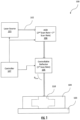
- the additive manufacturing device 100 illustratively includes a laser source 101 configured to generate a laser beam 102 , and a build material holder 103 configured to hold an additive build material 104.
- the build material holder 103 is configured to hold one of a metallic powder additive build material (e.g. powder bed fusion or direct energy deposition additive manufacturing device), a polymer powder additive build material (e.g. powder bed fusion or direct energy deposition additive manufacturing device), or a polymer liquid additive build material (e.g. photopolymerization additive manufacturing device) as will be appreciated by those skilled in the art.
- a metallic powder additive build material e.g. powder bed fusion or direct energy deposition additive manufacturing device
- a polymer powder additive build material e.g. powder bed fusion or direct energy deposition additive manufacturing device
- a polymer liquid additive build material e.g. photopolymerization additive manufacturing device
- other additive non-polymer build materials may be used.
- the additive manufacturing device 100 illustratively includes a controllable deflector 105 having a first scan rate.
- the controllable deflector 105 may comprise a movable mirror, for example, a Galvanometric mirror.
- the additive manufacturing device 100 illustratively includes an AOD 106 coupled upstream of the controllable deflector 105 and having a second scan rate faster than the first scan rate. It is noted that the additive manufacturing device 100 according to the present invention has at least one AOD 106 comprising first and second AODs 106.
- the simplified illustration of the embodiment in Fig.1 serves to explain the functional principle, but does not constitute an embodiment within the scope of protection of the invention. It should further be appreciated that some embodiments have more than one controllable deflector 105 and at least one AOD comprising first and second AODs 106 (See, e.g., FIG. 3 ) as described below.
- the additive manufacturing device 100 illustratively includes a controller 107 configured to control the controllable deflector 105 and the AOD 106 to scan the laser beam 102 relative to the build material holder 103 to additively manufacture a workpiece 110 in successive layers from the additive build material.
- the controller 107 is configured to control the controllable deflector 105 to define a trace of pixels on the additive build material, and while controlling the AOD 106 , to define an area of subpixels within each pixel.
- the scan method for the laser beam 102 may comprise raster scan method, for example.
- the controller 107 is configured to control the controllable deflector 105 and the AOD 106 to scan the laser beam 102 at a rate of an order of MHz, which is substantially faster than typical Galvanometric approaches.
- the controller 107 comprises control circuitry 111 , and RF drive circuitry 112 coupled between the control circuitry and the AOD 106.
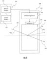
- the AOD 106 illustratively comprises an RF matching circuit 113 configured to receive an RF signal from the RF drive circuitry 112 , a transducer 114 receiving an output of the RF matching circuit and generating acoustic waves, and an acousto-optic bulk medium 115 coupled to the transducer and receiving the acoustic waves.
- the acousto-optic bulk medium 115 changes based upon the operational wavelength of the laser beam 102 .
- the acousto-optic bulk medium 115 may comprise quartz; when the operational wavelength of the laser beam 102 is 532nm, the acousto-optic bulk medium 115 may comprise tellurium dioxide; and when the operational wavelength of the laser beam 102 is 10 ⁇ m, the acousto-optic bulk medium 115 may comprise germanium.
- the AOD 106 has a controllable output intensity, and the controller 107 is configured to control the output intensity of the AOD.
- the AOD 106 divides the laser beam 102 (incident at an angle of ⁇ BRAGG ) from the laser source 101 into a first order scan beam 116 , and a zero order dump beam 117.
- the AOD 106 is configured to selectively refract the laser beam 102 at an angle of ⁇ AOD (i.e. the scan angle).
- the controller 107 is configured to attenuate the amplitude of the first order scan beam 116 , and the zero order dump beam 117. Since the first order scan beam 116 is passed to the controllable deflector 105 and eventually to the workpiece 110 , the controller 107 is capable of selectively adjusting the intensity, amplitude, and power of the laser beam imparted on the workpiece.
- the method includes operating a laser source 101 to generate a laser beam 102 directed towards a build material holder 103 holding an additive build material 104 , and operating a controller 107 to control a controllable deflector 105 and an AOD 106 to scan the laser beam relative to the build material holder to additively manufacture a workpiece 110 in successive layers from the additive build material.
- the controllable deflector 105 has have a first scan rate and the AOD 106 has a second scan rate faster than the first scan rate.
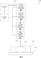
- this additive manufacturing device 200 differs from the previous embodiment in that this additive manufacturing device 200 illustratively includes a laser source 201 configured to generate a laser beam 202 , a build material holder 203 configured to hold an additive build material 204 , and a pair of controllable deflectors 205a-205b coupled sequentially (i.e. in series). Each controllable deflector 205a-205b has a first scan rate.
- the additive manufacturing device 200 illustratively includes a pair of AODs 206a-206b coupled sequentially upstream of the pair of controllable deflectors 205a-205b. It should be appreciated that imaging optics having a suitable magnification ratio can be introduced between the pair of AODs 206a-206b and between the pair of controllable deflectors 205a-205b to define the size of the scanned sub-pixel Gaussian beam intensity profile at the work surface when projected through a suitable F-Theta lens.
- the resolution of the additive manufacturing device 200 in many cases is increased by the magnification ratio and the non-raster scan capability of pair of AODs 206a-206b. They provide a means to distribute the same level of fluence across the entire work area in the same amount of time at much higher resolution when used in conjunction with the pair of controllable deflectors 205a-205b.
- Each AOD 206a-206b has a second scan rate faster than the first scan rate.
- the additive manufacturing device 200 illustratively includes a controller 207 configured to control the pair of controllable deflectors 205a-205b and the pair of AODs 206a-206b to scan the laser beam 202 relative to the build material holder 203 to additively manufacture a workpiece 210 in successive layers from the additive build material 204.
- the controller 207 is configured to control the pair of controllable deflectors 205a-205b to define a trace of pixels on the additive build material 204 , and while controlling the pair of AODs 206a-206b , to define an area of subpixels within each pixel.
- the pair of AODs 206a-206b comprises first and second AODs arranged to operate at orthogonal angles (i.e. horizontal and vertical scan).
- the pair of AODs 206a-206b is carried modularly in a separate housing (i.e. separate from downstream and upstream optical components). In these embodiments, the pair of AODs 206a-206b may be readily installed in the optical chain of additive manufacturing devices for upgrading the resolution and speed thereof.
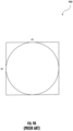
- a diagram 900 shows a scan pixel from a typical additive manufacturing device.
- diagram 900 shows the dimensions of the laser beam in the typical additive manufacturing device.
- the pixel covers an area of S1*S1 (e.g. 100pm x 100pm).
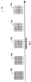
- a diagram 910 shows a pair of adjacent pixels 912a-912b.
- Each pixel 912a-912b now comprises a set of four subpixels 911a-911d , 911e-911h , effectively increasing the laser scanning resolution by a factor of 4.
- the laser beam 102 , 202 lases a subset of the subpixels 911a , 911d , 911e , 911h at the work surface.
- each subpixel 911a-911d , 911e-911h covers an area of S1/2*S1/2 (e.g. 50 ⁇ m ⁇ 50 ⁇ m).
- Formula 2 shows the raster scanned fluence along the scan direction produced without the use of pre-scan pair of AODs 206a-206b is: 4 ⁇ P o S 1 2 ⁇ S 1 2 ⁇ v 1 It can be seen that without the use of AOD pre-scan elements (i.e. the pair of AODs 206a-206b ), the linear scan velocity would have to increase by a factor of 2 for each subpixel to maintain the same fluence level. In order to complete the entire work layer at the higher indicated subpixel resolution in the same amount of time required at the original pixel resolution and fluence level, the raster scan velocity requires an increase by a factor equal to the increase in scanning beam resolution or ratio of the pixel to subpixel dimension.
- the write beam may be positioned at a nearly stationary location within a pixel region to localize the fluence produced by the subpixel write beam.
- Diagram 920 shows the position of the laser beam 102 at the work surface, where the subpixel beam position is constantly updated in relation to a raster scanned Galvanometric deflector to produce the desired local fluence without sacrificing the total scan build time.
- the initial beam offset from the current Galvanometric mirror beam angle position may be positive by one subpixel, and continuously updated to be directed to one subpixel in a direction opposite to the current raster scan Galvanometric mirror position.
- the AOD scan elements 206a-206b may direct the beam position to a new location within the original pixel region in a non-raster scanned fashion.
- the increase in resolution afforded by the manufacturing device 200 as determined by the number of subpixels within a pixel region, which may be on the order of N ⁇ 2, the number of resolvable angular positions produced by the AOD scan elements 206a-206b within the angle extent of the pixel region must be comparable.
- the requirements to meet this condition are given approximately by the Time-Bandwidth product of the respective AOD deflectors. It should be noted that this condition, along with the necessary update rate, is normally within the capability of this class of deflectors.
- Diagram 925 shows a single horizontal raster scan of pixels 926a-926e.
- Each pixel 926a-926e comprises a set of 30 subpixels, and the laser beam 102 lases a selective subset of the subpixels as it completes the horizontal raster scan.
- the laser beam 102 lases a decreasing subset of subpixels as it completes the horizontal raster scan from left to right.
- this illustrative depiction is merely exemplary, and any pattern of subpixel lasing is potential possible between adjacent pixels 926a-926e.
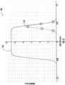
- a diagram 930 shows an intensity profile for the laser beam 102 , 202 in the additive manufacturing device 100 , 200.
- the AOD 106 , 106a-106b generates a Gaussian subpixel intensity profile 931 at the work surface, and the controller 107 , 207 is configured to control the AOD to define the fluence delivered to a flattened pixel intensity profile 932 relative to the Gaussian subpixel intensity profile.
- the flattened pixel intensity profile 932 is formed via arbitrary beam forming.
- the flattened pixel intensity profile 932 is formed through the summation of multiple iterations of the Gaussian subpixel intensity profile 931 over time. Since the laser beam 102 , 202 can move significantly faster and with greater resolution at the subpixel level, the flattened pixel intensity profile 932 can be achieved for the pixel level event.
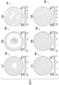
- diagrams 940 , 950 , 960 , 970 , 980a-980f show how the selective intensity profile for the laser beam 102 , 202 in the additive manufacturing device 100 , 200 can be used to create localized changes in the workpiece 110 , 210 .
- diagrams 940 , 950 show the hardness and porosity of the lased portion of the workpiece 110 , 210 at a high power level
- diagrams 960 , 970 show the hardness and porosity of the lased portion of the workpiece at a low power level.
- the additive manufacturing device 100 , 200 is able to selectively generate the workpiece 110 , 210 at the pixel level with set hardness and porosity.
- diagrams 980a-980f show varying intensity profiles for different pixels in the workpiece 110 , 210 using the additive manufacturing device 100 , 200 .
- the additive manufacturing device 100 , 200 disclosed herein uses fast AODs 106 , 206a-206b rather than the typical Galvanometric mirrors and field lenses. It should be appreciated that some embodiments would still include Galvanometric mirrors and an f-theta lens to have any reasonably large build envelope.
- the embodiment of the additive manufacturing device 200 in FIG. 3 uses a pair of orthogonal AODs 206a-206b upstream of the second controllable deflector 205b (e.g. scanning mirrors) to form arbitrary beam profiles in near real-time.
- the pair of orthogonal AODs 206a-206b each has a scanning rate orders of magnitude faster than mechanical scanning systems.
- the additive manufacturing device 200 can create arbitrary net beam profiles on the time-scale of the mechanical scanning element. Also, the additive manufacturing device 200 allows for a large beam when performing bulk scanning, and a finer beam when detailing edges, providing greater manufacturing flexibility. Moreover, it should be appreciated that the features of the additive manufacturing device 100 , 200 can be retrofitted onto existing additive manufacturing devices to enhance resolution and speed of manufacturing.
- the additive manufacturing device 100 , 200 disclosed herein provides the ability to adjust beam intensity during a scan, which has a significantly positive impact on final part properties.
- the inherent speed of AODs 106, 206a-206b allows adjustment without modulating laser, which allows the laser to run in its highest efficiency output mode.
- the flattened pixel intensity profile 932 in the additive manufacturing device 100, 200 may reduce cross-curing issues.
- the ability to change the beam shape relative to the direction of scan travel may have a significant impact on the microstructure of metal workpieces.
- modification of beam shape is achieved using anamorphic optics, which are not able to be adjusted during build.
- the additive manufacturing device 100, 200 disclosed herein can beam shape on the fly and in real-time.
Landscapes
- Engineering & Computer Science (AREA)
- Physics & Mathematics (AREA)
- Optics & Photonics (AREA)
- Chemical & Material Sciences (AREA)
- Materials Engineering (AREA)
- Mechanical Engineering (AREA)
- Manufacturing & Machinery (AREA)
- Plasma & Fusion (AREA)
- Toxicology (AREA)
- Health & Medical Sciences (AREA)
- Nonlinear Science (AREA)
- General Physics & Mathematics (AREA)
- Automation & Control Theory (AREA)
- General Health & Medical Sciences (AREA)
- Powder Metallurgy (AREA)
- Laser Beam Processing (AREA)
Claims (6)
- Eine Vorrichtung zur additiven Fertigung (100), die Folgendes umfasst:eine Laserquelle (101), die zur Erzeugung eines Laserstrahls (102) konfiguriert ist;einen Baumaterialhalter (103), der zur Aufnahme eines additiven Baumaterials (104) konfiguriert ist;mindestens einen steuerbaren Deflektor (105) mit einer ersten Abtastrate;mindestens einen akusto-optischen Deflektor AOD (106) mit einer zweiten Abtastrate, die schneller ist als die erste Abtastrate; undeine Steuerung (107), die so konfiguriert ist, dass sie den mindestens einen steuerbaren Deflektor (105) und den mindestens einen AOD steuert, um den Laserstrahl relativ zu dem Aufbaumaterialhalter abzutasten, um ein Werkstück (110) in aufeinanderfolgenden Schichten aus dem additiv aufgebauten Material additiv herzustellendadurch gekennzeichnet, dass der mindestens eine AOD (106) eine steuerbare Ausgangsintensität aufweist, wobei die Steuerung (107) so konfiguriert ist, dass sie die Ausgangsintensität des mindestens einen AOD (106) durch Dämpfung der Amplitude eines Abtaststrahls erster Ordnung (116) und eines Ablenkstrahls nullter Ordnung (117) steuert, wobei der AOD (106) so konfiguriert ist, dass er den unter einem Winkel von θBRAGG von der Laserquelle (101) einfallenden Laserstrahl (102) in den Abtaststrahl (116) erster Ordnung und den Ablenkstrahl (117) nullter Ordnung aufteilt, wobei der AOD (106) ferner so konfiguriert ist, dass er den Laserstrahl (102) unter einem Winkel von θAOD selektiv bricht, wobei der mindestens eine AOD (106) ein Gaußsches Subpixel-Intensitätsprofil (931) an der Arbeitsfläche erzeugt; und wobei die Steuerung (107) so konfiguriert ist, dass sie den mindestens einen AOD (106) so steuert, dass er ein abgeflachtes Pixel-Intensitätsprofil (932) relativ zu dem Gaußschen Subpixel-Intensitätsprofil (931) definiert, wobei das abgeflachte Pixel-Intensitätsprofil (932) durch die Summierung mehrerer Iterationen des Gaußschen Subpixel-Intensitätsprofils (931) über die Zeit gebildet wird; und wobei der mindestens eine AOD (106) einen ersten und einen zweiten AOD (106) umfasst, die so angeordnet sind, dass sie unter orthogonalen Winkeln arbeiten.
- Die Vorrichtung zur additiven Fertigung (100) nach Anspruch 1, wobei die Steuerung (107) so konfiguriert ist, dass sie den mindestens einen steuerbaren Deflektor (105) so steuert, dass er eine Spur von Pixeln auf dem additiven Aufbaumaterial definiert, und gleichzeitig den mindestens einen AOD (106) so steuert, dass er einen Bereich von Subpixeln innerhalb jedes Pixels definiert.
- Die Vorrichtung zur additiven Fertigung (100) nach Anspruch 1, wobei die Steuerung (107) einen Steuerschaltkreis und einen Hochfrequenz-Ansteuerschaltkreis (113) umfasst, der zwischen dem Steuerschaltkreis und dem mindestens einen AOD (106) gekoppelt ist.
- Die Vorrichtung zur additiven Fertigung (100) nach Anspruch 1, wobei der mindestens eine steuerbare Deflektor (105) mindestens einen beweglichen Spiegel umfasst.
- Ein additives Herstellungsverfahren, das Folgendes umfasst:Betreiben einer Laserquelle (101), um einen Laserstrahl (102) zu erzeugen, der auf einen Aufbaumaterialhalter (103) gerichtet ist, der ein additives Baumaterial (104) hält; undBetreiben einer Steuerung (107), um mindestens einen steuerbaren Deflektor (105) und mindestens einen akusto-optischen Deflektor, AOD, (106) zu steuern, um den Laserstrahl relativ zu dem Aufbaumaterialhalter (103) abzutasten, um ein Werkstück in aufeinanderfolgenden Schichten aus dem additiven Aufbaumaterial additiv herzustellen, wobei der mindestens eine steuerbare Deflektor (105) eine erste Abtastrate und der mindestens eine AOD (106) eine zweite Abtastrate aufweist, die schneller als die erste Abtastrate ist;dadurch gekennzeichnet, dass der mindestens eine AOD (106) eine steuerbare Ausgangsintensität aufweist, wobei der AOD (106) so konfiguriert ist, dass er den unter einem Winkel von θBRAGG von der Laserquelle (101) einfallenden Laserstrahl (102) in einen Abtaststrahl erster Ordnung (116) und einen Ablenkstrahl nullter Ordnung (117) aufteilt, und der AOD (106) ferner so konfiguriert ist, dass er den Laserstrahl (102) unter einem Winkel von θAOD selektiv bricht; und wobei die Steuerung (107) so konfiguriert ist, dass sie die Ausgangsintensität des mindestens einen AOD (106) durch Abschwächen der Amplitude des Abtaststrahls erster Ordnung (116) und des Ablenkstrahls nullter Ordnung (117) steuert, wobei der mindestens eine AOD (106) ein Gauß'sches Subpixel-Intensitätsprofil an der Arbeitsfläche erzeugt; und wobei das Betreiben der Steuerung (107) das Betreiben der Steuerung (107) umfasst, um den mindestens einen AOD (106) zu steuern, um ein abgeflachtes Pixel-Intensitätsprofil relativ zu dem Gauß'schen Subpixel-Intensitätsprofil zu definieren , wobei das abgeflachte Pixel-Intensitätsprofil (932) durch die Summierung mehrerer Iterationen des Gauß'schen Subpixel-Intensitätsprofils (931) über die Zeit gebildet wird ; und wobei das mindestens eine AOD (106) erste und zweite AODs (106) umfasst, die so angeordnet sind, dass sie unter orthogonalen Winkeln arbeiten.
- Verfahren nach Anspruch 5, wobei das Betreiben der Steuerung (107) das Betreiben der Steuerung (107) umfasst, um den mindestens einen steuerbaren Deflektor (105) zu steuern, um eine Spur von Pixeln auf dem additiv aufgebauten Material (104) zu definieren, und während das mindestens eine AOD (106) gesteuert wird, um einen Bereich von Subpixeln innerhalb jedes Pixels zu definieren.
Applications Claiming Priority (1)
| Application Number | Priority Date | Filing Date | Title |
|---|---|---|---|
| US17/096,074 US12070898B2 (en) | 2020-11-12 | 2020-11-12 | Additive manufacturing device with acousto-optic deflector and related methods |
Publications (2)
| Publication Number | Publication Date |
|---|---|
| EP4000773A1 EP4000773A1 (de) | 2022-05-25 |
| EP4000773B1 true EP4000773B1 (de) | 2024-07-31 |
Family
ID=78179336
Family Applications (1)
| Application Number | Title | Priority Date | Filing Date |
|---|---|---|---|
| EP21202536.5A Active EP4000773B1 (de) | 2020-11-12 | 2021-10-13 | Vorrichtung zur generativen fertigung mit akusto-optischem deflektor und zugehörige verfahren |
Country Status (2)
| Country | Link |
|---|---|
| US (1) | US12070898B2 (de) |
| EP (1) | EP4000773B1 (de) |
Family Cites Families (19)
| Publication number | Priority date | Publication date | Assignee | Title |
|---|---|---|---|---|
| US5837962A (en) | 1996-07-15 | 1998-11-17 | Overbeck; James W. | Faster laser marker employing acousto-optic deflection |
| US6341029B1 (en) | 1999-04-27 | 2002-01-22 | Gsi Lumonics, Inc. | Method and apparatus for shaping a laser-beam intensity profile by dithering |
| US7435927B2 (en) | 2004-06-18 | 2008-10-14 | Electron Scientific Industries, Inc. | Semiconductor link processing using multiple laterally spaced laser beam spots with on-axis offset |
| GB0800333D0 (en) * | 2008-01-09 | 2008-02-20 | Ucl Business Plc | Beam deflection apparatus and methods |
| US8680430B2 (en) | 2008-12-08 | 2014-03-25 | Electro Scientific Industries, Inc. | Controlling dynamic and thermal loads on laser beam positioning system to achieve high-throughput laser processing of workpiece features |
| TWI594828B (zh) | 2009-05-28 | 2017-08-11 | 伊雷克托科學工業股份有限公司 | 應用於雷射處理工件中的特徵的聲光偏轉器及相關雷射處理方法 |
| KR102383125B1 (ko) | 2010-10-22 | 2022-04-08 | 일렉트로 싸이언티픽 인더스트리이즈 인코포레이티드 | 빔 디더링 및 스카이빙을 위한 레이저 처리 시스템 및 방법 |
| CN106255567B (zh) | 2014-05-22 | 2019-04-12 | 英特尔公司 | 用于光束转向的具有多个换能器的声光偏转器 |
| WO2017100695A1 (en) * | 2015-12-10 | 2017-06-15 | Velo3D, Inc. | Skillful three-dimensional printing |
| US10690928B2 (en) | 2016-09-29 | 2020-06-23 | Nlight, Inc. | Methods of and systems for heat deposition in additive manufacturing |
| US20180207725A1 (en) | 2017-01-23 | 2018-07-26 | The Chinese University Of Hong Kong | System and method for fabricating 3d metal structure |
| US20180311760A1 (en) * | 2017-04-28 | 2018-11-01 | Divergent Technologies, Inc. | Powder-bed fusion beam scanning |
| KR102577671B1 (ko) | 2017-11-15 | 2023-09-12 | 그라낫 리서치, 리미티드 | 금속 액적 분사 시스템 |
| KR102778985B1 (ko) * | 2018-06-05 | 2025-03-12 | 일렉트로 싸이언티픽 인더스트리이즈 인코포레이티드 | 레이저 가공 장치, 그 작동 방법 및 이를 사용한 작업물 가공 방법 |
| DE102018213675A1 (de) * | 2018-08-14 | 2020-02-20 | Eos Gmbh Electro Optical Systems | Additive Herstellvorrichtung und zugeordnetes additives Herstellverfahren |
| DE102018125731A1 (de) | 2018-10-17 | 2020-04-23 | SLM Solutions Group AG | Verfahren und Vorrichtung zum Herstellen eines dreidimensionalen Werkstücks |
| TWI781243B (zh) | 2018-10-31 | 2022-10-21 | 國立清華大學 | 級聯鏡列及包含其之掃描系統 |
| TWI892641B (zh) * | 2019-01-31 | 2025-08-01 | 美商伊雷克托科學工業股份有限公司 | 光學系統 |
| CN113710407B (zh) * | 2019-06-10 | 2024-11-26 | 伊雷克托科学工业股份有限公司 | 镭射加工设备、其操作方法以及使用其加工工件的方法 |
-
2020
- 2020-11-12 US US17/096,074 patent/US12070898B2/en active Active
-
2021
- 2021-10-13 EP EP21202536.5A patent/EP4000773B1/de active Active
Also Published As
| Publication number | Publication date |
|---|---|
| US20220143905A1 (en) | 2022-05-12 |
| EP4000773A1 (de) | 2022-05-25 |
| US12070898B2 (en) | 2024-08-27 |
Similar Documents
| Publication | Publication Date | Title |
|---|---|---|
| Gillner et al. | High Power Laser Processing with Ultrafast and Multi-Parallel Beams. | |
| JP6022038B2 (ja) | レーザビームによるワークピースの処理方法および処理装置 | |
| US6861613B1 (en) | Device and method for the preparation of building components from a combination of materials | |
| EP1935620B1 (de) | Optische Modelliervorrichtung und optische Modellierverfahren | |
| JP2022517490A (ja) | 付加製造用のレーザ制御システム | |
| US20180272611A1 (en) | Device and generative layer-building process for producing a three-dimensional object by multiple beams | |
| EP3866999B1 (de) | Verfahren und vorrichtung zum herstellen eines dreidimensionalen werkstücks | |
| DE112009003829T5 (de) | Pulslaser-Verarbeitungsvorrichtung | |
| CN105121088B (zh) | 激光处理设备和经由激光工具操作而处理工件的方法 | |
| EP3050664B1 (de) | Laserbearbeitungssystem und verfahren | |
| KR20170120100A (ko) | 횡축 미세 기계 가공을 위한 고속 빔 조작 | |
| US12397349B2 (en) | Angled scanning of laser arrays in additive manufacturing | |
| KR20170119674A (ko) | 대면적 개질을 위한 레이저 시스템 및 방법 | |
| KR101897337B1 (ko) | 레이저 광선이 다중으로 편향되는 기판을 레이저 가공하기 위한 방법 및 장치 | |
| KR20150101430A (ko) | 사각 펄스 레이저 리프트 오프 | |
| CN113276409A (zh) | 增材制造方法、增材制造设备和计算机可读介质 | |
| EP0624421A2 (de) | Verfahren und Vorrichtung zur Herstellung eines Bildes in einem durchsichtigen Material mittels eines gepulsten Laserstrahles | |
| US12070898B2 (en) | Additive manufacturing device with acousto-optic deflector and related methods | |
| JP2012006040A (ja) | パルスレーザ加工方法 | |
| US20220362853A1 (en) | Grayscale Area Printing for Additive Manufacturing | |
| KR20170096504A (ko) | 기계가공을 적용한 대면적용 레이저 스캐너 기반 3차원 프린팅 장치 | |
| CN113825587B (zh) | 在材料表面上产生虹彩视觉效应的方法、实施所述方法的设备和由此获得的部件 | |
| US20230143334A1 (en) | Manufacturing device for additive manufacturing of component parts from a powder material, method for changing a beam profile of an energy beam, and use of at least one acousto-optic deflector | |
| WO2025008711A1 (en) | Laser irradiation method, laser irradiation device, laser marking device, and fabricating apparatus | |
| US20230147300A1 (en) | Manufacturing device and method for the additive manufacturing of a component part from a powder material, and method for producing a specific intensity profile of an energy beam |
Legal Events
| Date | Code | Title | Description |
|---|---|---|---|
| PUAI | Public reference made under article 153(3) epc to a published international application that has entered the european phase |
Free format text: ORIGINAL CODE: 0009012 |
|
| STAA | Information on the status of an ep patent application or granted ep patent |
Free format text: STATUS: REQUEST FOR EXAMINATION WAS MADE |
|
| 17P | Request for examination filed |
Effective date: 20211013 |
|
| AK | Designated contracting states |
Kind code of ref document: A1 Designated state(s): AL AT BE BG CH CY CZ DE DK EE ES FI FR GB GR HR HU IE IS IT LI LT LU LV MC MK MT NL NO PL PT RO RS SE SI SK SM TR |
|
| STAA | Information on the status of an ep patent application or granted ep patent |
Free format text: STATUS: EXAMINATION IS IN PROGRESS |
|
| 17Q | First examination report despatched |
Effective date: 20231220 |
|
| GRAP | Despatch of communication of intention to grant a patent |
Free format text: ORIGINAL CODE: EPIDOSNIGR1 |
|
| STAA | Information on the status of an ep patent application or granted ep patent |
Free format text: STATUS: GRANT OF PATENT IS INTENDED |
|
| RIC1 | Information provided on ipc code assigned before grant |
Ipc: G02F 1/33 20060101ALN20240502BHEP Ipc: B23K 26/06 20140101ALN20240502BHEP Ipc: H01S 3/106 20060101ALN20240502BHEP Ipc: G02B 26/10 20060101ALN20240502BHEP Ipc: B22F 10/366 20210101ALI20240502BHEP Ipc: B22F 12/49 20210101ALI20240502BHEP Ipc: B33Y 30/00 20150101ALI20240502BHEP Ipc: B33Y 10/00 20150101ALI20240502BHEP Ipc: B22F 10/20 20210101AFI20240502BHEP |
|
| INTG | Intention to grant announced |
Effective date: 20240524 |
|
| RIN1 | Information on inventor provided before grant (corrected) |
Inventor name: LOGAN, CATHERYN D. Inventor name: BRAUN, CARRIGAN L. Inventor name: PAOLELLA, ARTHUR C. Inventor name: WASILOUSKY, PETER ALAN Inventor name: MORSE, RANDALL K. Inventor name: COREY, CHRISTOPHER A. |
|
| GRAS | Grant fee paid |
Free format text: ORIGINAL CODE: EPIDOSNIGR3 |
|
| GRAA | (expected) grant |
Free format text: ORIGINAL CODE: 0009210 |
|
| STAA | Information on the status of an ep patent application or granted ep patent |
Free format text: STATUS: THE PATENT HAS BEEN GRANTED |
|
| AK | Designated contracting states |
Kind code of ref document: B1 Designated state(s): AL AT BE BG CH CY CZ DE DK EE ES FI FR GB GR HR HU IE IS IT LI LT LU LV MC MK MT NL NO PL PT RO RS SE SI SK SM TR |
|
| P01 | Opt-out of the competence of the unified patent court (upc) registered |
Free format text: CASE NUMBER: APP_37271/2024 Effective date: 20240621 |
|
| REG | Reference to a national code |
Ref country code: CH Ref legal event code: EP Ref country code: GB Ref legal event code: FG4D |
|
| REG | Reference to a national code |
Ref country code: DE Ref legal event code: R096 Ref document number: 602021016404 Country of ref document: DE |
|
| REG | Reference to a national code |
Ref country code: IE Ref legal event code: FG4D |
|
| REG | Reference to a national code |
Ref country code: LT Ref legal event code: MG9D |
|
| REG | Reference to a national code |
Ref country code: NL Ref legal event code: MP Effective date: 20240731 |
|
| PG25 | Lapsed in a contracting state [announced via postgrant information from national office to epo] |
Ref country code: PT Free format text: LAPSE BECAUSE OF FAILURE TO SUBMIT A TRANSLATION OF THE DESCRIPTION OR TO PAY THE FEE WITHIN THE PRESCRIBED TIME-LIMIT Effective date: 20241202 |
|
| REG | Reference to a national code |
Ref country code: AT Ref legal event code: MK05 Ref document number: 1708023 Country of ref document: AT Kind code of ref document: T Effective date: 20240731 |
|
| PG25 | Lapsed in a contracting state [announced via postgrant information from national office to epo] |
Ref country code: PT Free format text: LAPSE BECAUSE OF FAILURE TO SUBMIT A TRANSLATION OF THE DESCRIPTION OR TO PAY THE FEE WITHIN THE PRESCRIBED TIME-LIMIT Effective date: 20241202 |
|
| PG25 | Lapsed in a contracting state [announced via postgrant information from national office to epo] |
Ref country code: NO Free format text: LAPSE BECAUSE OF FAILURE TO SUBMIT A TRANSLATION OF THE DESCRIPTION OR TO PAY THE FEE WITHIN THE PRESCRIBED TIME-LIMIT Effective date: 20241031 |
|
| PG25 | Lapsed in a contracting state [announced via postgrant information from national office to epo] |
Ref country code: NL Free format text: LAPSE BECAUSE OF FAILURE TO SUBMIT A TRANSLATION OF THE DESCRIPTION OR TO PAY THE FEE WITHIN THE PRESCRIBED TIME-LIMIT Effective date: 20240731 Ref country code: GR Free format text: LAPSE BECAUSE OF FAILURE TO SUBMIT A TRANSLATION OF THE DESCRIPTION OR TO PAY THE FEE WITHIN THE PRESCRIBED TIME-LIMIT Effective date: 20241101 Ref country code: PL Free format text: LAPSE BECAUSE OF FAILURE TO SUBMIT A TRANSLATION OF THE DESCRIPTION OR TO PAY THE FEE WITHIN THE PRESCRIBED TIME-LIMIT Effective date: 20240731 Ref country code: FI Free format text: LAPSE BECAUSE OF FAILURE TO SUBMIT A TRANSLATION OF THE DESCRIPTION OR TO PAY THE FEE WITHIN THE PRESCRIBED TIME-LIMIT Effective date: 20240731 |
|
| PG25 | Lapsed in a contracting state [announced via postgrant information from national office to epo] |
Ref country code: BG Free format text: LAPSE BECAUSE OF FAILURE TO SUBMIT A TRANSLATION OF THE DESCRIPTION OR TO PAY THE FEE WITHIN THE PRESCRIBED TIME-LIMIT Effective date: 20240731 |
|
| PG25 | Lapsed in a contracting state [announced via postgrant information from national office to epo] |
Ref country code: LV Free format text: LAPSE BECAUSE OF FAILURE TO SUBMIT A TRANSLATION OF THE DESCRIPTION OR TO PAY THE FEE WITHIN THE PRESCRIBED TIME-LIMIT Effective date: 20240731 |
|
| PG25 | Lapsed in a contracting state [announced via postgrant information from national office to epo] |
Ref country code: IS Free format text: LAPSE BECAUSE OF FAILURE TO SUBMIT A TRANSLATION OF THE DESCRIPTION OR TO PAY THE FEE WITHIN THE PRESCRIBED TIME-LIMIT Effective date: 20241130 Ref country code: AT Free format text: LAPSE BECAUSE OF FAILURE TO SUBMIT A TRANSLATION OF THE DESCRIPTION OR TO PAY THE FEE WITHIN THE PRESCRIBED TIME-LIMIT Effective date: 20240731 |
|
| PG25 | Lapsed in a contracting state [announced via postgrant information from national office to epo] |
Ref country code: HR Free format text: LAPSE BECAUSE OF FAILURE TO SUBMIT A TRANSLATION OF THE DESCRIPTION OR TO PAY THE FEE WITHIN THE PRESCRIBED TIME-LIMIT Effective date: 20240731 |
|
| PG25 | Lapsed in a contracting state [announced via postgrant information from national office to epo] |
Ref country code: ES Free format text: LAPSE BECAUSE OF FAILURE TO SUBMIT A TRANSLATION OF THE DESCRIPTION OR TO PAY THE FEE WITHIN THE PRESCRIBED TIME-LIMIT Effective date: 20240731 Ref country code: RS Free format text: LAPSE BECAUSE OF FAILURE TO SUBMIT A TRANSLATION OF THE DESCRIPTION OR TO PAY THE FEE WITHIN THE PRESCRIBED TIME-LIMIT Effective date: 20241031 |
|
| PG25 | Lapsed in a contracting state [announced via postgrant information from national office to epo] |
Ref country code: RS Free format text: LAPSE BECAUSE OF FAILURE TO SUBMIT A TRANSLATION OF THE DESCRIPTION OR TO PAY THE FEE WITHIN THE PRESCRIBED TIME-LIMIT Effective date: 20241031 Ref country code: PL Free format text: LAPSE BECAUSE OF FAILURE TO SUBMIT A TRANSLATION OF THE DESCRIPTION OR TO PAY THE FEE WITHIN THE PRESCRIBED TIME-LIMIT Effective date: 20240731 Ref country code: NO Free format text: LAPSE BECAUSE OF FAILURE TO SUBMIT A TRANSLATION OF THE DESCRIPTION OR TO PAY THE FEE WITHIN THE PRESCRIBED TIME-LIMIT Effective date: 20241031 Ref country code: NL Free format text: LAPSE BECAUSE OF FAILURE TO SUBMIT A TRANSLATION OF THE DESCRIPTION OR TO PAY THE FEE WITHIN THE PRESCRIBED TIME-LIMIT Effective date: 20240731 Ref country code: LV Free format text: LAPSE BECAUSE OF FAILURE TO SUBMIT A TRANSLATION OF THE DESCRIPTION OR TO PAY THE FEE WITHIN THE PRESCRIBED TIME-LIMIT Effective date: 20240731 Ref country code: IS Free format text: LAPSE BECAUSE OF FAILURE TO SUBMIT A TRANSLATION OF THE DESCRIPTION OR TO PAY THE FEE WITHIN THE PRESCRIBED TIME-LIMIT Effective date: 20241130 Ref country code: HR Free format text: LAPSE BECAUSE OF FAILURE TO SUBMIT A TRANSLATION OF THE DESCRIPTION OR TO PAY THE FEE WITHIN THE PRESCRIBED TIME-LIMIT Effective date: 20240731 Ref country code: GR Free format text: LAPSE BECAUSE OF FAILURE TO SUBMIT A TRANSLATION OF THE DESCRIPTION OR TO PAY THE FEE WITHIN THE PRESCRIBED TIME-LIMIT Effective date: 20241101 Ref country code: FI Free format text: LAPSE BECAUSE OF FAILURE TO SUBMIT A TRANSLATION OF THE DESCRIPTION OR TO PAY THE FEE WITHIN THE PRESCRIBED TIME-LIMIT Effective date: 20240731 Ref country code: ES Free format text: LAPSE BECAUSE OF FAILURE TO SUBMIT A TRANSLATION OF THE DESCRIPTION OR TO PAY THE FEE WITHIN THE PRESCRIBED TIME-LIMIT Effective date: 20240731 Ref country code: BG Free format text: LAPSE BECAUSE OF FAILURE TO SUBMIT A TRANSLATION OF THE DESCRIPTION OR TO PAY THE FEE WITHIN THE PRESCRIBED TIME-LIMIT Effective date: 20240731 Ref country code: AT Free format text: LAPSE BECAUSE OF FAILURE TO SUBMIT A TRANSLATION OF THE DESCRIPTION OR TO PAY THE FEE WITHIN THE PRESCRIBED TIME-LIMIT Effective date: 20240731 |
|
| PG25 | Lapsed in a contracting state [announced via postgrant information from national office to epo] |
Ref country code: RO Free format text: LAPSE BECAUSE OF FAILURE TO SUBMIT A TRANSLATION OF THE DESCRIPTION OR TO PAY THE FEE WITHIN THE PRESCRIBED TIME-LIMIT Effective date: 20240731 Ref country code: DK Free format text: LAPSE BECAUSE OF FAILURE TO SUBMIT A TRANSLATION OF THE DESCRIPTION OR TO PAY THE FEE WITHIN THE PRESCRIBED TIME-LIMIT Effective date: 20240731 Ref country code: SM Free format text: LAPSE BECAUSE OF FAILURE TO SUBMIT A TRANSLATION OF THE DESCRIPTION OR TO PAY THE FEE WITHIN THE PRESCRIBED TIME-LIMIT Effective date: 20240731 |
|
| PG25 | Lapsed in a contracting state [announced via postgrant information from national office to epo] |
Ref country code: EE Free format text: LAPSE BECAUSE OF FAILURE TO SUBMIT A TRANSLATION OF THE DESCRIPTION OR TO PAY THE FEE WITHIN THE PRESCRIBED TIME-LIMIT Effective date: 20240731 |
|
| PG25 | Lapsed in a contracting state [announced via postgrant information from national office to epo] |
Ref country code: CZ Free format text: LAPSE BECAUSE OF FAILURE TO SUBMIT A TRANSLATION OF THE DESCRIPTION OR TO PAY THE FEE WITHIN THE PRESCRIBED TIME-LIMIT Effective date: 20240731 |
|
| PG25 | Lapsed in a contracting state [announced via postgrant information from national office to epo] |
Ref country code: SK Free format text: LAPSE BECAUSE OF FAILURE TO SUBMIT A TRANSLATION OF THE DESCRIPTION OR TO PAY THE FEE WITHIN THE PRESCRIBED TIME-LIMIT Effective date: 20240731 Ref country code: IT Free format text: LAPSE BECAUSE OF FAILURE TO SUBMIT A TRANSLATION OF THE DESCRIPTION OR TO PAY THE FEE WITHIN THE PRESCRIBED TIME-LIMIT Effective date: 20240731 |
|
| REG | Reference to a national code |
Ref country code: DE Ref legal event code: R097 Ref document number: 602021016404 Country of ref document: DE |
|
| REG | Reference to a national code |
Ref country code: CH Ref legal event code: PL |
|
| PLBE | No opposition filed within time limit |
Free format text: ORIGINAL CODE: 0009261 |
|
| STAA | Information on the status of an ep patent application or granted ep patent |
Free format text: STATUS: NO OPPOSITION FILED WITHIN TIME LIMIT |
|
| PG25 | Lapsed in a contracting state [announced via postgrant information from national office to epo] |
Ref country code: MC Free format text: LAPSE BECAUSE OF FAILURE TO SUBMIT A TRANSLATION OF THE DESCRIPTION OR TO PAY THE FEE WITHIN THE PRESCRIBED TIME-LIMIT Effective date: 20240731 |
|
| 26N | No opposition filed |
Effective date: 20250501 |
|
| PG25 | Lapsed in a contracting state [announced via postgrant information from national office to epo] |
Ref country code: LU Free format text: LAPSE BECAUSE OF NON-PAYMENT OF DUE FEES Effective date: 20241013 Ref country code: BE Free format text: LAPSE BECAUSE OF NON-PAYMENT OF DUE FEES Effective date: 20241031 |
|
| PG25 | Lapsed in a contracting state [announced via postgrant information from national office to epo] |
Ref country code: FR Free format text: LAPSE BECAUSE OF NON-PAYMENT OF DUE FEES Effective date: 20241031 |
|
| PG25 | Lapsed in a contracting state [announced via postgrant information from national office to epo] |
Ref country code: CH Free format text: LAPSE BECAUSE OF NON-PAYMENT OF DUE FEES Effective date: 20241031 |
|
| REG | Reference to a national code |
Ref country code: BE Ref legal event code: MM Effective date: 20241031 |
|
| PG25 | Lapsed in a contracting state [announced via postgrant information from national office to epo] |
Ref country code: SE Free format text: LAPSE BECAUSE OF FAILURE TO SUBMIT A TRANSLATION OF THE DESCRIPTION OR TO PAY THE FEE WITHIN THE PRESCRIBED TIME-LIMIT Effective date: 20240731 |
|
| PG25 | Lapsed in a contracting state [announced via postgrant information from national office to epo] |
Ref country code: IE Free format text: LAPSE BECAUSE OF NON-PAYMENT OF DUE FEES Effective date: 20241013 |
|
| PGFP | Annual fee paid to national office [announced via postgrant information from national office to epo] |
Ref country code: DE Payment date: 20251029 Year of fee payment: 5 |
|
| PGFP | Annual fee paid to national office [announced via postgrant information from national office to epo] |
Ref country code: GB Payment date: 20251027 Year of fee payment: 5 |
|
| PG25 | Lapsed in a contracting state [announced via postgrant information from national office to epo] |
Ref country code: CY Free format text: LAPSE BECAUSE OF FAILURE TO SUBMIT A TRANSLATION OF THE DESCRIPTION OR TO PAY THE FEE WITHIN THE PRESCRIBED TIME-LIMIT; INVALID AB INITIO Effective date: 20211013 |
|
| PG25 | Lapsed in a contracting state [announced via postgrant information from national office to epo] |
Ref country code: HU Free format text: LAPSE BECAUSE OF FAILURE TO SUBMIT A TRANSLATION OF THE DESCRIPTION OR TO PAY THE FEE WITHIN THE PRESCRIBED TIME-LIMIT; INVALID AB INITIO Effective date: 20211013 |
|
| PG25 | Lapsed in a contracting state [announced via postgrant information from national office to epo] |
Ref country code: TR Free format text: LAPSE BECAUSE OF FAILURE TO SUBMIT A TRANSLATION OF THE DESCRIPTION OR TO PAY THE FEE WITHIN THE PRESCRIBED TIME-LIMIT Effective date: 20240731 |
|
| PG25 | Lapsed in a contracting state [announced via postgrant information from national office to epo] |
Ref country code: SI Free format text: LAPSE BECAUSE OF FAILURE TO SUBMIT A TRANSLATION OF THE DESCRIPTION OR TO PAY THE FEE WITHIN THE PRESCRIBED TIME-LIMIT Effective date: 20240731 |
|
| PG25 | Lapsed in a contracting state [announced via postgrant information from national office to epo] |
Ref country code: LT Free format text: LAPSE BECAUSE OF FAILURE TO SUBMIT A TRANSLATION OF THE DESCRIPTION OR TO PAY THE FEE WITHIN THE PRESCRIBED TIME-LIMIT Effective date: 20240731 |